Abstract
We demonstrate a novel high-speed and broadband laser architecture based on stretched pulse active mode locking that provides a wavelength-swept and wavelength-stepped output. The laser utilizes a single intracavity 8.3 meter chirped fiber Bragg grating to generate positive and negative dispersion, and can be operated with or without an intracavity fixed Fabry–Perot etalon to generate wavelength-swept and wavelength-stepped (frequency comb) outputs, respectively. Using a four-path delay line at the output, we achieved 16.3MHz repetition rates and a 62 nm lasing bandwidth centered at 1550 nm. Single-sided double-pass coherence lengths of 1.25 mm for the wavelength-swept configuration and more than 30 mm for the wavelength-stepped configuration were obtained. Relative intensity noise was measured to be better than −140 dB/Hz. The stretched-pulse mode-locked architecture utilizing long chirped fiber Bragg gratings offers a simple and compact design for a broadband wavelength-tuned output at unprecedented speeds, and can address the need for fast sources in applications such as optical ranging, imaging, and sensing.
Wavelength-swept and wavelength-stepped lasers are essential tools in numerous applications, including ranging, spectroscopy, optical imaging (including optical coherence tomography), optical sensing, and device test and measurement [1–4]. Many commercially available external-cavity tunable laser designs are available when the tuning speed is not critical. However, in applications such as sensing, ranging, and imaging, the tuning speed can be of paramount importance. For these applications, high-speed laser architectures have been developed based on MEMs Fabry–Perot filters [5], spinning polygon mirrors [6], tunable VCSELs [7], and electronically tunable DBR lasers [8], among others. These designs have produced lasers with repetition rates from 100 kHz to several megahertz [9], with the fastest speeds being generated by resonant MEMs Fabry–Perot filters used in Fourier-domain mode-locked architectures [10]. However, for a variety of reasons, including limitations imposed by mechanical-based filters, it is difficult to scale these designs to higher speeds.
To address the need for higher repetition-rate wavelengths-wept and wavelength-stepped lasers, we recently demonstrated a stretched-pulse active mode locking (SPML) architecture operating at 18.9 MHz [11]. In this SPML laser, 39.394 km of positive dispersion fiber (SMF28) and 5.26 km of negative dispersion compensating fiber (DCF) were included in the cavity [11]. These dispersive fibers time-stretched a short optical output generated by an actively driven electro-optic modulator [12–14]. This time-stretching created the wavelength-tuned (stretched and/or stepped) output and eliminated gain-competition in the semiconductor optical amplifier (SOA). The wavelength-repetition rates were set by the magnitude of the dispersion, and no mechanical elements were required. While this design produced an extremely fast and broadband output, the use of extremely long fibers brought several disadvantages. First, the laser round-trip time was highly sensitive to temperature, and the drive signal frequencies needed to be adjusted at 5–10 min intervals. Second, these fibers induced large cavity losses that necessitated the use of two SOAs [11] which, in turn, resulted in significant nonlinear interactions. Third, because of the limited availability of matched positive and negative dispersive fibers outside the 1.55 μm spectral range, this design is not easily translatable throughout the near-infrared spectrum. Finally, the laser could not be compact in size due to the large size of the fiber spools.
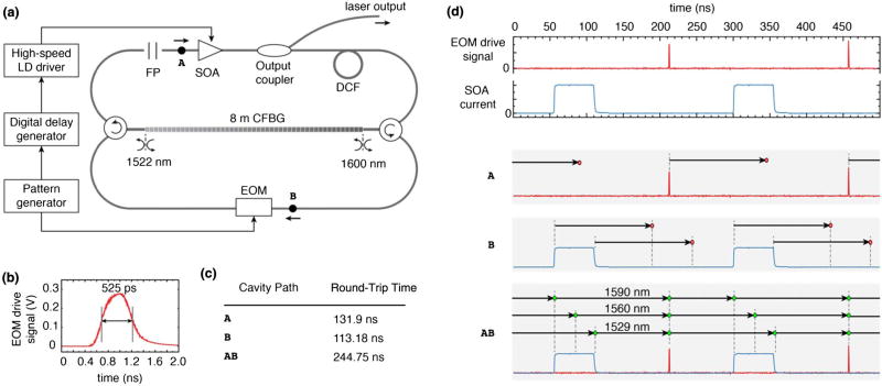
In this Letter, we demonstrate a significantly improved SPML laser architecture that uses a single 8.3 meter continuously chirped fiber Bragg grating (CFBG) in place of the positive and negative dispersive fibers. The CFBG-based SPML laser is based on the theta-cavity layout [15], as shown in Fig. 1(a). An electro-optic modulator (Covega) was driven with a ~525 ps pulse [Fig. 1(b)] (Sympulse, PAT 5000) that was repeated in resonance with a harmonic of the cavity round-trip time. The gain medium is an SOA (Covega) with 3 dB bandwidth of 102 nm. The CFBG was placed between two circulators to allow access to both positive and negative dispersion [16]. The 8.3 m CFBG (Proximion) operated over a continuous wavelength range from 1522 to 1605. The grating was designed to produce a linear group delay with respect to optical frequency. The dispersion at 1550 nm was ±930 ps/nm (equivalent to that provided by approximately 55 km of SMF28 fiber). By using the CFBG from both directions, we generated matched positive and negative dispersion from the same device. The insertion loss of the CFBG used in the reflection mode was 1.36 dB for the near-side reflected wavelength and 1.71 dB for wavelengths that reflect from the far end of the grating. The laser output was taken after the SOA using a 20% output tap coupler. Approximately 9 m of DCF (−38.5 ps/nm/km at 1550 nm) was added to the cavity. It was found empirically that this length of DCF improved the noise performance of the laser, presumably by offsetting dispersion from the cavity SMF fiber or residual dispersion from the CFBG. To generate a wavelength-stepped (frequency comb) output, a fixed fused silica FP etalon with 80 GHz FSR (~0.64 nm) and low finesse (~5) was included [17].
Fig. 1.
(a) Experimental configuration of the CFBG-SPML laser. EOM, electro-optic modulator; CFBG, chirped fiber Bragg grating; FP, Fabry–Perot etalon; SOA, semiconductor optical amplifier; DCF, dispersion compensated fiber. (b) Electronic drive pulse provided to the EOM. (c) Round-trip times for cavities A, B, and AB. (d) EOM and SOA modulation signals (upper panel) were used to suppress light circulation in short cavities A and B, while allowing circulation in cavity AB (lower panel).
Within the CFBG passband, approximately 30% of the light is transmitted. This partial transmission creates three optical cavities. These cavities can be labeled by their inclusion of either or both points A and B [Fig. 1(a)]. The longest cavity, created by a reflection of light from the CFBG from both sides, includes both points (cavity AB). This cavity generates the desired lasing. Two shorter cavities are generated by light transmitted through the CFBG: cavity A (upper loop) and cavity B (lower loop). Short cavity B has no optical gain, but can generate multi-path reflections of circulating light. Cavity A contains the SOA and can generate lasing. Without suppression, lasing within cavity A prevented long-cavity (AB) lasing.
To suppress light circulating in cavities A and B, we used SOA and EOM modulation. Cavities A and B were designed with round-trip times that were approximately half that of the long cavity AB [Fig. 1(c)]. The SOA drive current was then modulated on/off at a frequency given by the cavity AB roundtrip time and with a less than 50% duty cycle. As a result, light generated by the SOA and traveling cavity A returns to the SOA in an off state [Fig. 1(d)]. Similarly, the EOM repetition frequency was set to avoid resonance with the cavity B round-trip time. In the implemented configuration, we drove the SOA with a 61 ns pulse. The round trip of the long cavity (AB) was 244.75 ns (approximately 50.1 m), almost four times larger. This yielded a 25% duty cycle at the laser output. To increase the repetition rate, we used a four-path delay line to increase the repetition rate and duty cycle, resulting in a 16.3MHz repetition rate. A booster SOA was used after the delay lines.
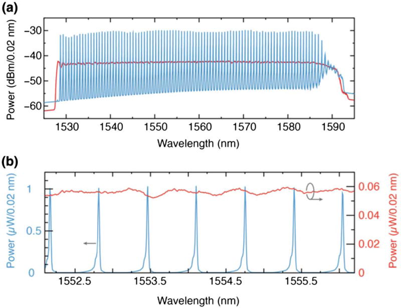
The output spectrum of the laser after the four-path delay line and booster SOA is plotted in Fig. 2 for continuous [without FP etalon, Fig. 2(a)] and frequency comb [with FP etalon, Fig. 2(b)] configurations. In each, the SOA drive current pulse of 61 ns limited lasing bandwidth to ~62 nm (1525–1587). In the frequency comb configuration, output lines spaced by 80 GHz are observed with FWHM linewidth below the 0.02 nm resolution of the optical spectrum analyzer. The output power of the laser before 4× delay lines was 1.7 and 1.5 mW for the continuously swept and frequency comb configurations, respectively. These power measurements are low in part due to the 25% duty cycle at this location. After the delay lines and booster amplification, the output power was 35 mW for both continuous and frequency comb configurations. The laser performance declined in the range from 1585–1590 nm. We observed that this unstable region tracks with the time during which the SOA current is being modulated off and is independent of wavelength. As such, it is likely generated by instabilities associated with SOA modulation.
Fig. 2.
Output optical spectrum of the continuous (red) and frequency comb (blue) configurations (a) across the full bandwidth and (b) over a limited wavelength span.
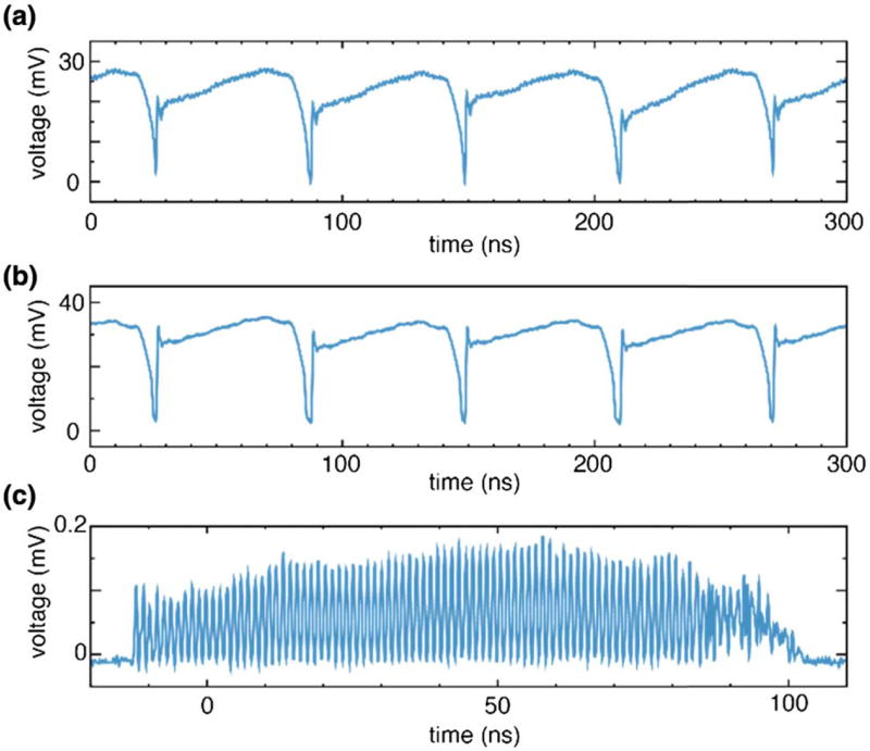
Figure 3 shows output traces of the laser (after delay line and booster SOA) measured with an 8 GHz photoreceiver (Thorlabs PDA8GS) and a 2 GHz oscilloscope (Tektronix MSO5204) for continuous [Fig. 3(a)] and frequency comb [Fig. 3(b)] configurations. For the continuous trace, we note that the observable variations in optical power are largely a fixed pattern noise. The noise performance of the sources is described later in this Letter. The frequency comb output shows a similar, but slightly smaller, fixed pattern noise. Of note in the frequency comb output is the apparent gap-free output, which differs from the prior frequency comb SPML laser design. This can be explained by noting that the CFBG dispersion (at 1550) was 930 ps/nm, and the comb spacing (at 1550) was 0.64 nm. This predicts a 595 ps separation between pulses, only slightly larger than the 525 ps EOM pulse width. This makes detection of the pulses difficult using a 2 GHz bandwidth scope. To confirm that this output is composed of individual wavelength pulses, we used a second CFBG of equal dispersion external to the laser cavity to stretch the laser output (without the delay lines).
Fig. 3.
Output traces of the (a) continuous and (b) frequency comb configurations. (c) Frequency comb output trace without delay line quadrupling of the repetition rate was time-stretched by a second CFBG to confirm the underlying pulse structure.
These measurements confirmed the anticipated pulse structure in the time- domain [Fig. 3(c)]. We also note the appearance of the high-noise region at the end of the pulse train as described above. It is important to note that this external cavity dispersive stretching was only used to reveal the temporal-spectral pulse structure in Fig. 3(c); all other measurements were performed on the laser outputs as shown in Figs. 3(a) and 3(b).
The coherence properties of the continuously swept and frequency comb configurations are shown in Fig. 4. For each, the coherence length was measured by detecting fringes generated by a Mach–Zehnder interferometer. For the continuous wavelength-swept configuration, this fringe signal was detected using the 8 GHz photoreceiver, and the fringe amplitude was measured using an RF spectrum analyzer (Anritsu MS2036C). The fringe amplitude as a function of the mirror position relative to the zero delay point is plotted in Fig. 4(a). Because the frequency comb configuration recycles fringe RF frequencies in a confined RF baseband as the mirror translates [17], we measured fringe amplitude using an 800 MHz photoreceiver (New Focus 1617) and an AlazarTech 9373 digitizer. The reference arm measurement was subtracted from these fringes, and the amplitude of the fringe was calculated as a function of mirror position. As shown in Fig. 4(b), the frequency comb configuration provided much longer coherence lengths.
Fig. 4.
Measured coherence properties of the (a) continuous wavelength-swept and (b) frequency comb configurations.
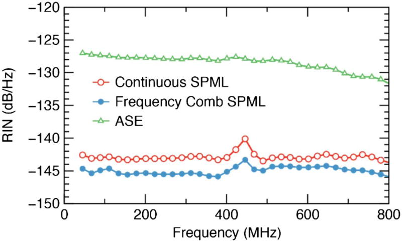
The relative intensity noise (RIN) of the laser is presented in Fig. 5. The RIN was measured using an 800 MHz photoreceiver and the AlazarTech digitizer. DC measurements were obtained using the monitor output on the photoreceiver, taking into account the different AC and DC responsivities from the photoreceiver. The RIN was calculated on digitized laser output traces after reference-trace subtraction; the reference trace was calculated by averaging across more than 1000 sequential laser repetitions. This removed fixed-pattern structure from the noise measurements. A Hanning window was applied across the laser trace, and the noise was calculated by FFT. The measured RIN levels of approximately −140 and −145 dB/Hz for the continuously swept and frequency comb configurations are excellent in comparison to the reported values of other wavelength-swept sources [18]. For comparison and validation of our measurements, we applied our RIN measurement method to the amplified spontaneous emission (ASE) output of the booster amplifier and obtained −128 dB/Hz at 400 MHz, which was in agreement with theoretical predictions for the broadband thermal light source and with previously reported measurements [18].
Fig. 5.
RIN of the sources in comparison with that of the SOA amplified spontaneous ASE.
In conclusion, we demonstrate the use of meter-scale CFBGs in broadband SPML lasers. Using this design, we demonstrate continuous wavelength sweeping and frequency comb wavelength stepping with a repetition rate of 16.3 MHz. A lasing bandwidth of 61 nm was achieved. In principle, the CFBG design can be extended to support larger bandwidth lasing. Single-sided double-pass coherence lengths for the frequency comb output exceeded 3 cm and 1.25 mm for the continuous wavelength-swept configuration. The noise performance of each configuration was measured to be better than −140 dB/Hz. In addition, we note that the CFBG was designed to provide a linear group delay with optical frequency, and the laser output showed highly linear-in-wavenumber sweeping/stepping that has significant advantages in many ranging and imaging applications. This CFBG SPML laser architecture has significant potential to address the need for rapid and broadband wavelength-tuned lasers in multiple applications.
Acknowledgments
Funding. National Institutes of Health (NIH) (R01CA163528, P41EB015903); DOD/AFOSR (FA9550-11-1-0331).
This research was sponsored by NIH, DOD/AFOSR, and a Wellman Center Bullock post-doctoral fellowship (MS).
References
- 1.Ryu HY, Lee W-K, Moon HS, Suh HS. Opt. Commun. 2007;275:379. [Google Scholar]
- 2.Danielson BL, Boisrobert CY. Appl. Opt. 1991;30:2975. doi: 10.1364/AO.30.002975. [DOI] [PubMed] [Google Scholar]
- 3.Yun SH, Boudoux C, Tearney GJ, Bouma BE. Opt. Lett. 2003;28:1981. doi: 10.1364/ol.28.001981. [DOI] [PubMed] [Google Scholar]
- 4.Derickson D, editor. Fiber Optic Test and Measurement. Prentice Hall: 1998. [Google Scholar]
- 5.Jun C, Villiger M, Oh WY, Bouma BE. Opt. Express. 2014;22:25805. doi: 10.1364/OE.22.025805. [DOI] [PMC free article] [PubMed] [Google Scholar]
- 6.Oh WY, Vakoc BJ, Shishkov M, Tearney GJ, Bouma BE. Opt. Lett. 2010;35:2919. doi: 10.1364/OL.35.002919. [DOI] [PMC free article] [PubMed] [Google Scholar]
- 7.Jayaraman V, Cole GD, Robertson M, Burgner C, John D, Uddin A, Cable A. Electron. Lett. 2012;48:1331. doi: 10.1049/el.2012.3180. [DOI] [PMC free article] [PubMed] [Google Scholar]
- 8.Murata S, Mito I, Kobayashi K. Electron. Lett. 1988;24:577. [Google Scholar]
- 9.Huber R, Wojtkowski M, Fujimoto JG. Opt. Express. 2006;14:3225. doi: 10.1364/oe.14.003225. [DOI] [PubMed] [Google Scholar]
- 10.Wieser W, Biedermann BR, Klein T, Eigenwillig CM, Huber R. Opt. Express. 2010;18:14685. doi: 10.1364/OE.18.014685. [DOI] [PubMed] [Google Scholar]
- 11.Tozburun S, Siddiqui M, Vakoc BJ. Opt. Express. 2014;22:3414. doi: 10.1364/OE.22.003414. [DOI] [PMC free article] [PubMed] [Google Scholar]
- 12.Tamura K, Ippen EP, Haus HA, Nelson LE. Opt. Lett. 1993;18:1080. doi: 10.1364/ol.18.001080. [DOI] [PubMed] [Google Scholar]
- 13.Haus HA, Taruma K, Nelson LE, Ippen EP. IEEE J. Quantum Electron. 1995;31:591. [Google Scholar]
- 14.Yamashita S, Asano M. Opt. Express. 2006;14:9399. doi: 10.1364/oe.14.009399. [DOI] [PubMed] [Google Scholar]
- 15.Lee S, Kim K, Delfyett PJ. IEEE Photon. Technol. Lett. 2006;18:799. [Google Scholar]
- 16.Lee S, Mandridis D, Delfyett PJ. Opt. Express. 2008;16:4766. doi: 10.1364/oe.16.004766. [DOI] [PubMed] [Google Scholar]
- 17.Siddiqui M, Vakoc BJ. Opt. Express. 2012;20:17938. doi: 10.1364/OE.20.017938. [DOI] [PMC free article] [PubMed] [Google Scholar]
- 18.Biedermann BR, Wieser W, Eigenwillig CM, Klein T, Huber R. Opt. Express. 2009;17:9947. doi: 10.1364/oe.17.009947. [DOI] [PubMed] [Google Scholar]


