Abstract
We present a comparative study between a series of well-known semiconductor polymers, used in efficient organic solar cells as hole transport materials (HTM), and the state-of-the art material used as hole transport material in perovskite solar cells: the spiro-OMeTAD. The observed differences in solar cell efficiencies are studied in depth using advanced photoinduced spectroscopic techniques under working illumination conditions. We have observed that there is no correlation between the highest occupied molecular orbital (HOMO) energy levels of the organic semiconductors and the measured open-circuit voltage (VOC). For instance, spiro-OMeTAD and P3HT have a comparable HOMO level of ~5.2 eV vs vacuum even though a difference in VOC of around 200 mV is recorded. This difference is in good agreement with the shift observed for the charge vs voltage measurements. Moreover, hole transfer from the perovskite to the HTM, estimated qualitatively from fluorescence quenching and emission lifetime, seems less efficient for the polymeric HTMs. Finally, the recombination currents from all devices were estimated by using the measured charge (calculated using photoinduced differential charging) and the carriers’ lifetime and their value resulted in accordance with the registered short-circuit currents (JSC) at 1 sun.
Introduction
In the last few years, the field of photovoltaic has been flooded by the appearance of perovskite1, a wide-ranging class of materials for solar cells which have nowadays pushed its power efficiency beyond 20%2, 3 with a certified record of 22.1% under standard measurement conditions4. The perovskite materials can be described by the general formula ABX3, where A is the organic cation (often methylammonium, CH3NH3 + or formamidinium, CH(NH2)2)+, B is the inorganic cation (typically Pb2+), and X is the halide (I−, Cl− or Br−). A fine-tuning of the perovskite materials and the band-gap has led to the current record efficiency.
Starting from precursor solutions5–8 or via multi-source thermal evaporation9, 10, various methods have been developed to form a high quality layer of perovskite and many of them actually give rise to stable, reproducible and efficient solar cells also depending on the architecture of the whole device. The most employed configuration of perovskite solar cells (PSC), namely ‘regular’ structure consists of: a transparent conductive fluorine doped tin oxide (FTO); a metal oxide layer which, in turn, can be mesoporous (mesoscopic architecture) or compact (planar architecture) acting as the electron transporting material (ETM); the perovskite absorber; the HTM and a metal contact (usually gold or silver). In addition, PSC have been successfully fabricated also in the ‘inverted’ planar configuration (a typical structure in organic solar cells, OSC), with indium doped tin oxide (ITO) as the transparent conductive electrode.
Since the breakthrough of PSC, a myriad of new organic semiconductor materials have been synthesized and tested as HTM11–18. However, so far, none of them have display efficiencies above 20%. In fact, semiconductor polymers, that have provided a step forward towards OSC highest efficiencies, have not achieved performances close to those recorded for spiro-OMeTAD19. Hence, the solid state organic semiconductor used as selective contact for holes has remained the well-known spiro-OMeTAD, with the exception of poly(triarylamine) (PTAA)20, 21, to achieve top efficiencies.
In this paper we aim to study efficient PSC using three of the most representative semiconductor polymers like poly(3-hexylthiophene-2,5-diyl) (P3HT), poly[2,6-(4,4-bis-(2-ethylhexyl)-4H-cyclopenta[2,1-b;3,4-b′]dithiophene)-alt-4,7(2,1,3-benzothiadiazole)] (PCPDTBT) and poly[[4,8-bis[(2-ethylhexyl)oxy]benzo[1,2-b:4,5-b’]dithiophene-2,6-diyl][3-fluoro-2-[(2-ethylhexyl)carbonyl]thieno[3,4-b]thiophenediyl]] (PTB7), depicted in Fig. 1, and understand the reasons that hamper these materials to reach higher efficiencies when used as hole selective contacts.
Figure 1.
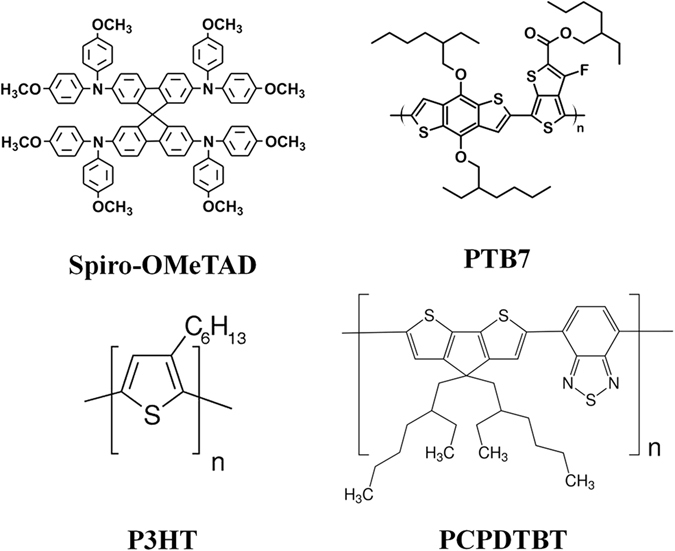
Molecular structure of the HTMs employed in this study.
Efficiency losses in solar cells account for the presence of radiative recombination within the semiconductor material and interfacial carrier recombination (non-radiative) processes22–25. We have measured the charge in the solar cell at different light intensities, which lead to different solar cell VOC (so called light bias). As we demonstrated before26, unlike OSC and dye-sensitized solar cells (DSSC), the measured charge in PSC depends on the acquisition method. Photoinduced charge extraction (PICE) is a direct measurement which allows the estimation of the overall charge generated upon illumination while photoinduced differential charging (PIDC) calculates the amount of charge from the so called “differential capacitance”, obtained as a result of the combination of small perturbation transient techniques. The carrier recombination lifetimes have been measured by photoinduced transient photovoltage (PI-TPV) under solar cell open-circuit conditions.
Results
Solar cells characterization
The current density-voltage (J-V) characteristics of the best devices are shown in Fig. 2. These measurements were carried out under 1 sun illumination conditions (AM1.5G, 100 mW/cm2) and performing the voltage scan in the direction VOC to JSC (reverse sweep). All cells present substantial hysteresis in the J-V (see Table 1 and Figure S1) leading to a difference in photovoltaic parameters depending on the scan direction and rate, as observed by many research groups27, 28. The cause for this behavior is yet to be unequivocally determined. Mobile ions migration in the perovskite material has been proposed as a possible explanation for hysteresis by Unger et al.29, although very recently Belisle at al. demonstrated that this occurrence alone cannot explain the observed phenomenon30. In any case, the origin of the hysteresis is not the focus of this work and will not be discussed in this manuscript.
Figure 2.
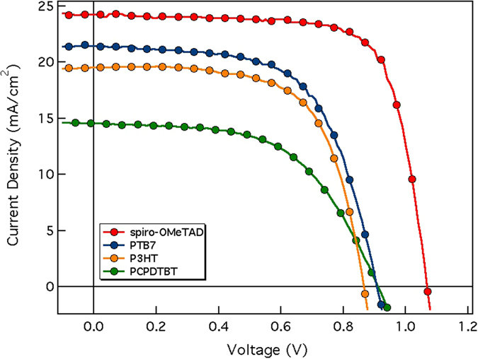
J-V graphs of the devices measured under standard (AM 1.5G) 1 sun conditions from VOC to JSC (champion cells).
Table 1.
Photovoltaic parameters of the devices characterized in this study under standard 1 sun illumination.
| HTM | Sweep | VOC (mV) | JSC (mA/cm2) | FF (%) | PCE (%) |
|---|---|---|---|---|---|
| Spiro-OMeTAD | F | 936 | 24.4 | 55.1 | 12.6 (9.0 ± 1.5) |
| R | 1068 | 24.3 | 73.6 | 19.1 (14.9 ± 2.0) | |
| PTB7 | F | 856 | 21.3 | 44.7 | 8.2 (7.2 ± 1.2) |
| R | 908 | 21.4 | 61.9 | 12.0 (10.8 ± 1.2) | |
| P3HT | F | 807 | 17.8 | 34.0 | 4.9 (4.8 ± 0.8) |
| R | 866 | 19.6 | 65.1 | 11.0 (10.2 ± 0.9) | |
| PCPDTBT | F | 853 | 13.4 | 42.8 | 4.9 (4.6 ± 0.6) |
| R | 911 | 14.6 | 56.0 | 7.4 (6.5 ± 1.0) |
Each value corresponds to the champion cell. The PCE value between parentheses is the average of eight solar cells.
In our case, both VOC and JSC of spiro-OMeTAD cells are greater than the other polymers cells as shown in Fig. 2 (“champion cells”) and reported in Table 1.
It is worthy to mention that spiro-OMeTAD based cells efficiencies are in agreement with the ones reported by most of the groups working on methylammonium lead iodide (MAPI, perovskite bandgap 1.6 eV) solar cells. Regarding polymer based cells, in this study we have surpassed the reported power conversion efficiency (PCE) record for PCPDTBT acting as HTM20, while for P3HT and PTB7, the efficiencies obtained are similar to the best efficiencies reported avoiding the use of dopants31, 32.
In Fig. 3 we illustrated the HOMO and lowest unoccupied molecular orbital (LUMO) levels for all the HTM employed in this study as reported by Wright et al.33. From the values obtained, it appears evident that the differences in VOC of the cells could not be simply related to the differences in the HOMO energy level of the HTM since they are alike.
Figure 3.
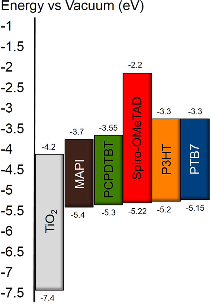
Energy level diagram of the different materials employed.
We first measured the JSC dependence with light intensity (LI). Figure 4 (left) shows a power law dependence of JSC on LI (JSC proportional to LIα with α close to 1 for each HTM (αspiro-OMeTAD = 0.98; αPTB7 = 0.97; αP3HT = 0.92; αPCPDTBT = 0.94). These values indicate minimal light intensity dependence for charge collection, suggesting that free-carriers recombination processes at short-circuit are negligible34.
Figure 4.
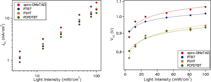
Light intensity dependence of JSC (left) and VOC (right) for the structure FTO/TiO2/MAPI/HTM/Au.
From Fig. 4 (right) we can observe the variation of VOC with LI. The values obtained with the reverse sweeps have been taken into account since they coincide with the VOC obtained after a short stabilization time (see Figure S3). A first approach to the origin of the charge recombination that occurs in a device can be studied by examining the ideality factor (nid), which can be obtained from Eq. 1, applied to the dependence of VOC with LI:
| 1 |
where e is the elementary charge and kT is the thermal energy. Generally, the ideality factor ranges from 1 to 2, where nid = 1 indicates direct free carrier recombination (ideal case) while nid > 1 suggests that the recombination is trap mediated35, 36 with higher values corresponding to the presence of deep traps. In our case, the trap mediated recombination is predominant, as the values are very close to 2, (nid,spiro-OMeTAD = 2.2; nid,P3HT = 2.2; nid,PCPDTBT = 1.7) except in the case of PTB7 (nid,PTB7 = 1.4).
Time resolved photoluminescence decay
Time resolved photoluminescence (TRPL) has been employed to analyze radiative recombination dynamics in perovskite-based solar cells37–39. The TRPL response was acquired using time-correlated single-photon counting (TCSPC) technique to measure the resulting decay.
The photoluminescence (PL) spectra of the perovskite\HTM films on the glass substrate (see Figure S4) show a single emission peak, centered at 750 nm, with negligible differences depending on the HTM.
The TRPL decays are shown in Fig. 5. These decays can be fitted to a bi-exponential function (Eq. 2)37, 38:
| 2 |
Figure 5.
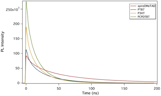
PL decays of the perovskite\HTM films on glass substrate.
where A1 and A2 are the relative amplitudes of the components and τ1 and τ2 the lifetimes associated to the fast and slow recombination, respectively.
The fast one is associated with charge carrier extraction by the layers37, 39, which corroborate the efficient charge transfer to the HTM, while the slow component is associated with carriers in the perovskite that do not quench. Both lifetimes change from one HTM to another (see Table 2). Comparing the τ2 of the different perovskite/HTM we can conclude that the fastest lifetimes obtained for the polymers which, in turn, imply an increase of recombination within the perovskite, is one of the reasons for the lower efficiency of the respective solar devices.
Table 2.
| Sample | τ1 (ns) | τ2 (ns) |
|---|---|---|
| MAPI without HTM | — | 116.3 |
| MAPI/Spiro-OMeTAD | 9.4 | 60.0 |
| MAPI/PTB7 | 5.0 | 30.9 |
| MAPI/P3HT | 3.8 | 21.8 |
| MAPI/PCPDTBT | 4.4 | 20.2 |
In Fig. 5, the PL decays measured at the same acquisition time (the same excitation time period and recording of their luminescence) for each HTM are shown. As can be seen for PCPDTBT, the HTM that leads to lower device efficiencies, the perovskite luminescence amplitude is higher, which implies that hole transfer (luminescence quenching) from the perovskite to the HTM does not occur efficiently. Thus, the sequence of the efficiency of the hole transfer is PCPDTBT < P3HT < PTB7 < spiro-OMeTAD in agreement with the efficiencies measured and listed in Table 1.
Photoinduced Transient Techniques
Photoinduced transient techniques have been employed by our group18, 40, 41 and others42, 43 to study the interfacial carrier recombination dynamics in complete devices, including DSSC, organic and hybrid solar cells and recently PSC26, 44–46. As mentioned above, PICE has been demonstrated to be a consistent method to estimate the charge density in different types of solar cells and, together with PI-TPV, allows to evaluate the recombination current (Jrec).
However, as shown previously26, the amount of charge measured using PICE for PSC (in particular MAPI) resulted in an overestimation of the recombination current. To further confirm this fact we have calculated the total amount of charges obtained with PICE and indeed the recombination current does not match the expected value calculated at VOC (see Table ST2). Instead of PICE we employed the PIDC method, which is another technique that has been used to measure capacitance, and thus charge density, in both DSSC and OSC. The differential capacitance can be measured by combining PI-TPV and photoinduced transient photocurrent (PI-TPC) results to find C = dQ/dt/(dV/dt). In contrast with DSSC and OSC, for MAPI solar cells the PIDC and PICE methods does not yield to the same amount of stored charge. We will show later that, for the devices object of this study, the charge density obtained with the PIDC method allows to match (or fairly reproduce) the Jrec.
The quantity dV/dt, which is actually the amplitude of the pulse, can be estimated from PIT-PV at different open-circuit voltages induced by different light intensities. dV/dt increases as the light intensity (thus the VOC decreases). PI-TPV is a quantitative measurement, which allows the study of recombination processes in the device under working conditions. A continuous light bias is applied to the device and a laser pulse generates an additional amount of charges, which cannot be extracted as the device is in open circuit so they have to recombine. All the PI-TPV decays in our efficient solar cells show an exponential decay (see Figure S8) in which the time constant is associated with the interfacial carrier recombination between the electrons in the perovskite and the holes in the HTM, as demonstrated by Montcada et al.44. This is supported by a very good coverage of the TiO2 47 by the perovskite as can be seen in the cross-section SEM image illustrated in Fig. 6. The perovskite coverage avoids direct recombination channels between the TiO2 and the HTM. An irregular and insufficient perovskite coverage of the TiO2 leads to bi-exponential PI-TPV decays.
Figure 6.

SEM cross section of a MAPI solar cell with spiro-OMeTAD as HTM (left). The scheme with the different layers present in the devices (right).
As already observed in many type of solar cells, the charge carrier lifetime, obtained from a single PI-TPV decay, decreases with the increment of photo-induced VOC following the Eq. 3:
| 3 |
where τ is the carrier lifetime and β the constant decay.
All the τs have been estimated from the PI-TPV decays and the result is plotted in Fig. 7. PTB7 and spiro-OMeTAD present the fastest charge carrier lifetimes at 1 sun LI (1 μs) while for P3HT and PCPDTBT the τ is more than 2 μs (values reported Table 3). The calculated βs are 11.5 V−1 for PCPDTBT, 14.3 V−1 for P3HT, 15.2 V−1 for PTB7 and 21.5 V−1 for spiro-OMeTAD. Interestingly, the increase of the β value is coherent with the increase of the JSC extracted from the J-V curves.
Figure 7.
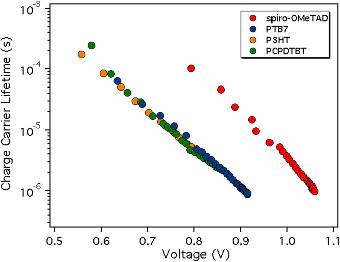
The different τ measured using PI-TPV vs light bias (photoinduced voltage).
Table 3.
Summary of charge density, carrier lifetime, and recombination current for each HTM based PSC.
| HTM | Q (nC/cm2) | τ (μs) | OF | Jrec (mA/cm2) | JSC (mA/cm2) |
|---|---|---|---|---|---|
| Spiro-OMeTAD | 157 | 0.98 | 6.4 | 25.0 | 24.3 |
| PTB7 | 115 | 0.92 | 4.7 | 26.6 | 19.6 |
| P3HT | 170 | 2.40 | 3.8 | 18.6 | 18.8 |
| PCPDTBT | 85 | 2.20 | 3.3 | 11.7 | 14.6 |
Specifically, Q is calculated with the PIDC method, τ is measured with PI-TPV at 1 sun background LI, Jrec is calculated from Eq. 4 and JSC is the experimental value obtained from J-V graphs in reverse sweep.
The PI-TPC has been employed in order to find dQ/dt, which represent the amount of charge generated during the pulse (small perturbation). This charge does not change with background light intensity (and thus VOC) as can be seen in Figure S9.
Figure 8 shows the differential capacitance at VOC measured at different light bias and the charge stored in the device obtained by integrating this capacitance over the voltage. These measurements show that there is a shift in voltage between the spiro-OMeTAD and the polymers in the obtained capacitance in good agreement with the difference in VOC between the solar cells.
Figure 8.
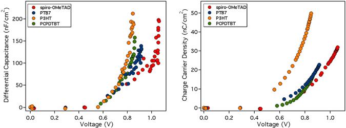
(Left) Capacitance at different voltages (light bias) after subtracting the geometrical capacitance and (right) the charge obtained upon integration of the capacitance at the same voltages.
To further evaluate the consistency of the measured charge using the PIDC method, we have related these values with the photocurrent of each device. To do so, we have calculated the recombination current (Jrec) at VOC in the device under 1 Sun illumination conditions by combining the carrier lifetimes obtained from PI-TPV (Fig. 7) and the charge density. Under these conditions (at open-circuit) the net flux of charge is zero meaning that all the generated charges in the device have recombined. Assuming that the generated current is approximately independent of cell voltage (which could implicitly lead to some degree of error in the current density evaluation) it can be set equal to the JSC. Thus, at open-circuit, Jrec should be equal to JSC. The recombination current Jrec is calculated using the following equation:
| 4 |
where Q(VOC) is the amount of charges calculated at 1 sun with PIDC, without subtracting the geometric capacitance of the cell (see Figure S10). The τ(VOC) is the carriers lifetime obtained from PI-TPV. The factor (1 + β/γ) is also known as the order factor (OF)26 in which β is the constant decay from Eq. 3 and γ indicates the slope of log(Q) vs voltage from PIDC (Fig. 8, right). In Fig. 9 we show the direct relationship between charge density and carrier lifetime.
Figure 9.
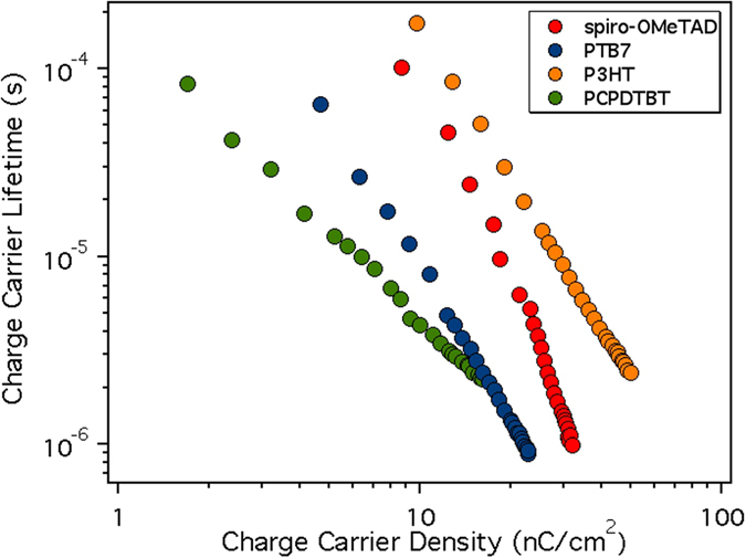
The carriers’ lifetime measured using PI-TPV versus the charge density.
From these calculations, summarized in Table 3, we obtained very reasonable results that approximate the experimental JSC, especially for spiro-OMeTAD and P3HT while there is a substantial mismatch in the cases of PTB7 and PCPDTBT. These results confirm that PI-TPV decays actually describe the recombination at the perovskite/HTM interface and, furthermore, that the PIDC is a reliable method to estimate the charge stored in the device.
The hole mobility values of the HTMs, as used in the MAPI solar cells, have been measured as described in the methods section. Figure 10 illustrates the J-V graphs of the devices based on the different materials. The obtained values are in accordance with the mobility values reported in the literature48–50, confirming that doped spiro-OMeTAD has a better hole transport with a μh of 1.5 × 10⁻³ cm2 V−1 s−1 while for the rest of the HTMs μh ranges from 2 to 4 × 10⁻⁴ cm2 V−1 s−1.
Figure 10.
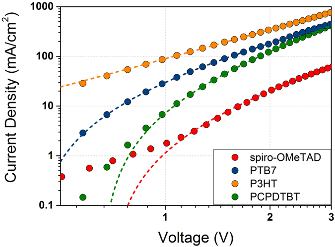
Current density vs. voltage measurements of the devices ITO/PEDOT:PSS/HTM/Au for each HTM used in this study. The dashed lines correspond to the fitting of the experimental data to Eq. 5.
Discussions
We have fabricated efficient perovskite solar cells using different organic polymer HTMs which have similar HOMO energy levels and we have compared their performance with the standard HTM spiro-OMeTAD. The results show that there is no direct correlation between the HTM HOMO level and the solar cell VOC. A first approximation to analyze the origin of the differences observed in VOC leads us to suggest that, on the one hand, in all cases the VOC is limited by trap mediated charge recombination. On the other hand, the measurement of the perovskite luminescence in the presence of the HTM shows that the most efficient hole transfer process occurs in the spiro-OMeTAD sample. In contrast, with PCPDTBT the hole transfer from the perovskite to the HTM is the less efficient of the polymers analyzed in this study. In fact, there is a direct relationship between the photoluminescence quenching and the efficiency of the perovskite solar cells.
The measurement of the functional devices under working conditions shows that there are differences on the obtained capacitance when using PIDC with a clear shift in voltage between the spiro-OMeTAD and the polymers. Moreover, the analysis of carriers’ lifetime shows that the τs are similar under 1 sun irradiation conditions. Furthermore, using the measured charge and the carrier lifetime it was feasible to obtain the recombination current at VOC, which is in good agreement with the experimentally measured JSC, as demonstrated before. Thus, it is unlikely that for the measured devices the carrier recombination is influenced by existing electric fields and carrier recombination between the electrons in the perovskite and the holes in the HTMs is the main process limiting the solar cell efficiencies.
In addition, the mobility values for the materials used in the solar cells were measured. Indeed, the doped spiro-OMeTAD shows the best charge mobility allowing for devices with thicker hole selective layer and, thus, avoiding potential shorts due to pin-holes.
Finally, we would like to stress that in the case of the spiro-OMeTAD, the LUMO energy gap (the energy difference between the perovskite conduction band and the LUMO of the HTM) was also the biggest in comparison with the polymers. It may well be that this is one of the factors, together with excellent hole mobility and good solubility, that leads to the best solar–to-energy conversion values in perovskite solar cell. Further efforts on the synthesis of new HTM in this direction are being carried out.
Methods
Materials
All materials were purchased from Sigma-Aldrich unless differently specified. Methylamonium iodide (CH3NH3I, MAI) was synthesized by dropping hydroiodic acid (HI, 57% conc. in H2O) into methylamine (CH3NH2, 40% conc. in EtOH, TCI) maintaining the temperature at 0 °C. Then, the mixture was left stirring for 2 hours at room temperature. The solution was rotavaporated at 60 °C until a white precipitate appeared and no solvent remained in the flask. This precipitate was filtered with vacuum, dissolved in methanol, re-precipitated with diethyl ether and filtered again. Finally, it was dried in a vacuum oven at 60 °C overnight. PbI2, spiro-OMeTAD, P3HT, PTB7 and PCPDTBT were used as received.
Device fabrication
FTO coated glasses (R = 8 Ω per square) were etched to obtain the desired pattern using zinc powder and hydrochloric acid (HCl, 2 M). The substrates were properly cleaned by ultrasonication in water with Hellmanex™ detergent, then in de-ionized water and finally in ethanol. A dense layer of TiO2 was deposited employing a solution of 0.65 mL of titanium (IV) isopropoxide and 0.38 mL of acetylacetone in 5 mL of ethanol that was spin coated at 3000 rpm for 60 s. Afterwards, the substrates were sintered at 500 °C for 30 min. Then, they were immersed in titanium (IV) chloride (TiCl4, 40 mM) at 70 °C for 30 min. They were sintered again at 500 °C for 30 min. Afterwards, mesoporous TiO2 was deposited by spin coating a commercial TiO2 paste (30 NR-D, Dyesol) diluted in ethanol 1:5.5 (w:w) at 5000 rpm for 30 s. The films were dried at 80 °C just after the deposition and finally sintered at 500 °C for 30 min. The perovskite was obtained with a two-step deposition method, analogue to the one described by Wang et al.51. In the first step, 1 M solution of lead iodide (PbI2, 99%) dissolved in a mixture of dimethylformamide:dimethyl sulfoxide (DMF:DMSO, 92:8) was spin coated at 2000 rpm for 90 s. In the second, a solution of MAI 50 mg/mL in isopropanol:ethanol (75:25), was dripped over the substrate 30 s before the spinning process ends. Successively, the films were annealed for 10 minutes at 100 °C. The HTM deposition differs between the spiro-OMeTAD deposition and the low band gap polymers. Spiro-OMeTAD (1-Material) solutions had a concentration of 72.3 mg/mL in chlorobenzene with the addition of 38.7 μL of tert-butylpyridine and 23.7 μL of Li-TFSI (stock solution of 520 mg/mL in acetonitrile) and it was spin coated at 2000 rpm for 60 s (film thickness around 150 nm). PTB7 (1-Material) and P3HT (Rieke Metals Inc.) had a concentration of 20 mg/mL and PCPDTBT (1-Material) 30 mg/mL in chlorobenzene and the use of any dopant was avoided. Low band-gap polymers solutions were spin coated at 1500 rpm for 30 s. The respective thicknesses, chosen after optimization of each HTM-based cell, are 90 nm for PTB7, 110 nm for P3HT and PCPDTBT. Finally, an 80 nm layer of gold (Kurt J. Lesker Company) was deposited by thermal evaporation.
Device characterization
J-V measurement curves
The J-V curves were measured using a solar simulator (ABET 11000) and a source meter (Keithley 2400). The curves were registered under 1 Sun conditions (100 mW/cm2, AM 1.5G) calibrated with a Si-reference cell. The active area of the devices was 0.09 cm2.
Time-correlated single photon counting
Both TCSPC and PL emission spectra were measured with a Picosecond Fluorescence Lifetime Spectrometer (LifeSpec II, Edinburgh Instruments) equipped with an adequate photomultiplier tube (PMT) and a 470 nm picosecond pulse laser.
Photoinduced Time Resolved Techniques
All these measurements were carried out using a homemade system. This setup is based on a ring of LEDs connected to a power supply to allow measurements with different light intensities in order to control the applied bias. For PICE measurements, the solar cell is connected to a homemade electronic board that switches between open-circuit and short-circuit. Both PI-TPV and PI-TPC need a small perturbation in voltage originated by a laser pulse (PTI 3300 Nitrogen laser with dye unit GL-301). All the signals are collected by a Yokogawa DLM2400 oscilloscope and processed with a Labview based homemade software.
Mobility measurements
The hole mobility of the HTMs under study has been estimated by means of hole-only devices, fabricated using a diode configuration of ITO/PEDOT:PSS/HTM/Au and by taking current-voltage measurements up to 4 or 5 V. The electric field dependent space-charge limited current (SCLC) mobility was estimated using the following equation:
| 5 |
where J is the current density, L is the film thickness of active layer (around 100 nm), μh is the hole mobility, ε r is the relative permittivity of the material (we assumed a value of 3, a fair assumption for organic materials), ε 0 is the permittivity of free space (8.85 × 10⁻¹² F/m), b is the field activation factor and V is the effective voltage in the device (which is the applied voltage corrected for the built-in, Vbi, and the voltage drop due to series and contacts resistances of the device).
Scanning electron microscopy (SEM)
The SEM images were acquired to estimate how the different layers of the devices were constructed. A Jeol JSM-6400 microscope was used to obtain the images.
Electronic supplementary material
Acknowledgements
The authors would like to acknowledge ICIQ-BIST (Severo Ochoa Excellence Accreditation 2014–2018 SEV-2013–0319) and ICREA for economical support. EP is also grateful to Spanish MINECO for the CTQ2016-80042-R project and Generalitat de Catalunya for the AGAUR funding.
Author Contributions
J.J. performed all the experimental measurements. J.J., W.C. and E.P. participated in the analysis and innterpretation of data. W.C., L.C. and E.P. supervised the experimental part. The manuscript was written through contributions of all authors. All authors have given approval to the final version of the manuscript.
Competing Interests
The authors declare that they have no competing interests.
Footnotes
Electronic supplementary material
Supplementary information accompanies this paper at doi:10.1038/s41598-017-06245-5
Publisher's note: Springer Nature remains neutral with regard to jurisdictional claims in published maps and institutional affiliations.
References
- 1.Kojima A, Teshima K, Shirai Y, Miyasaka T. Organometal Halide Perovskites as Visible-Light Sensitizers for Photovoltaic Cells. J. Am. Chem. Soc. 2009;131:6050–6051. doi: 10.1021/ja809598r. [DOI] [PubMed] [Google Scholar]
- 2.Yang WS, et al. High-performance photovoltaic perovskite layers fabricated through intramolecular exchange. Science. 2015;348:1234–1237. doi: 10.1126/science.aaa9272. [DOI] [PubMed] [Google Scholar]
- 3.Saliba M, et al. Cesium-containing triple cation perovskite solar cells: improved stability, reproducibility and high efficiency. Energy Environ. Sci. 2016;9:1989–1997. doi: 10.1039/C5EE03874J. [DOI] [PMC free article] [PubMed] [Google Scholar]
- 4.NREL, Efficiency Records Chart. http://www.nrel.gov/pv/assets/images/efficiency-chart.png, (Date of access:14/04/2017) (2017).
- 5.Burschka J, et al. Sequential deposition as a route to high-performance perovskite-sensitized solar cells. Nature. 2013;499:316–319. doi: 10.1038/nature12340. [DOI] [PubMed] [Google Scholar]
- 6.Xiao Z, et al. Efficient, high yield perovskite photovoltaic devices grown by interdiffusion of solution-processed precursor stacking layers. Energy Environ. Sci. 2014;7:2619–2623. doi: 10.1039/C4EE01138D. [DOI] [Google Scholar]
- 7.Jeon NJ, et al. Solvent engineering for high-performance inorganic-organic hybrid perovskite solar cells. Nat. Mater. 2014;13:897–903. doi: 10.1038/nmat4014. [DOI] [PubMed] [Google Scholar]
- 8.Eperon GE, Burlakov VM, Docampo P, Goriely A, Snaith HJ. Morphological Control for High Performance, Solution-Processed Planar Heterojunction Perovskite Solar Cells. Adv. Funct. Mater. 2014;24:151–157. doi: 10.1002/adfm.201302090. [DOI] [Google Scholar]
- 9.Liu M, Johnston MB, Snaith HJ. Efficient planar heterojunction perovskite solar cells by vapour deposition. Nature. 2013;501:395–398. doi: 10.1038/nature12509. [DOI] [PubMed] [Google Scholar]
- 10.Malinkiewicz O, et al. Perovskite solar cells employing organic charge-transport layers. Nat. Photon. 2014;8:128–132. doi: 10.1038/nphoton.2013.341. [DOI] [Google Scholar]
- 11.Saliba M, et al. A molecularly engineered hole-transporting material for efficient perovskite solar cells. Nat. Energy. 2016;1:15017. doi: 10.1038/nenergy.2015.17. [DOI] [Google Scholar]
- 12.Malinauskas T, et al. Branched methoxydiphenylamine-substituted fluorene derivatives as hole transporting materials for high-performance perovskite solar cells. Energy Environ. Sci. 2016;9:1681–1686. doi: 10.1039/C5EE03911H. [DOI] [Google Scholar]
- 13.Lim I, et al. Indolocarbazole based small molecules: an efficient hole transporting material for perovskite solar cells. RSC Adv. 2015;5:55321–55327. doi: 10.1039/C5RA10148D. [DOI] [Google Scholar]
- 14.Cho I, et al. Indolo[3,2-b]indole-based crystalline hole-transporting material for highly efficient perovskite solar cells. Chem. Sci. 2017;8:734–741. doi: 10.1039/C6SC02832B. [DOI] [PMC free article] [PubMed] [Google Scholar]
- 15.Do K, et al. Star-shaped hole transporting materials with a triazine unit for efficient perovskite solar cells. Chem. Commun. 2014;50:10971–10974. doi: 10.1039/C4CC04550E. [DOI] [PubMed] [Google Scholar]
- 16.Kazim S, et al. A dopant free linear acene derivative as a hole transport material for perovskite pigmented solar cells. Energy Environ. Sci. 2015;8:1816–1823. doi: 10.1039/C5EE00599J. [DOI] [Google Scholar]
- 17.Qin P, et al. Perovskite Solar Cells with 12.8% Efficiency by Using Conjugated Quinolizino Acridine Based Hole Transporting Material. J. Am. Chem. Soc. 2014;136:8516–8519. doi: 10.1021/ja503272q. [DOI] [PubMed] [Google Scholar]
- 18.Cabau L, et al. Diarylamino-substituted tetraarylethene (TAE) as an efficient and robust hole transport material for 11% methyl ammonium lead iodide perovskite solar cells. Chem. Commun. 2015;51:13980–13982. doi: 10.1039/C5CC05236J. [DOI] [PubMed] [Google Scholar]
- 19.Calió L, Kazim S, Grätzel M, Ahmad S. Hole-Transport Materials for Perovskite Solar Cells. Angew. Chem., Int. Ed. 2016;55:14522–14545. doi: 10.1002/anie.201601757. [DOI] [PubMed] [Google Scholar]
- 20.Heo JH, et al. Efficient inorganic-organic hybrid heterojunction solar cells containing perovskite compound and polymeric hole conductors. Nat. Photon. 2013;7:486–491. doi: 10.1038/nphoton.2013.80. [DOI] [Google Scholar]
- 21.Jeon NJ, et al. Compositional engineering of perovskite materials for high-performance solar cells. Nature. 2015;517:476–480. doi: 10.1038/nature14133. [DOI] [PubMed] [Google Scholar]
- 22.Gonzalez-Pedro V, et al. General Working Principles of CH3NH3PbX3 Perovskite Solar Cells. Nano Lett. 2014;14:888–893. doi: 10.1021/nl404252e. [DOI] [PubMed] [Google Scholar]
- 23.Kim H-S, et al. Mechanism of carrier accumulation in perovskite thin-absorber solar cells. Nat. Commun. 2013;4:2242. doi: 10.1038/ncomms3242. [DOI] [PubMed] [Google Scholar]
- 24.Guillén E, Ramos FJ, Anta JA, Ahmad S. Elucidating Transport-Recombination Mechanisms in Perovskite Solar Cells by Small-Perturbation Techniques. J. Phys. Chem. C. 2014;118:22913–22922. doi: 10.1021/jp5069076. [DOI] [Google Scholar]
- 25.Bi D, Yang L, Boschloo G, Hagfeldt A, Johansson EMJ. Effect of Different Hole Transport Materials on Recombination in CH3NH3PbI3 Perovskite-Sensitized Mesoscopic Solar Cells. J. Phys. Chem. Lett. 2013;4:1532–1536. doi: 10.1021/jz400638x. [DOI] [PubMed] [Google Scholar]
- 26.O’Regan BC, et al. Optoelectronic Studies of Methylammonium Lead Iodide Perovskite Solar Cells with Mesoporous TiO2: Separation of Electronic and Chemical Charge Storage, Understanding Two Recombination Lifetimes, and the Evolution of Band Offsets during J-V Hysteresis. J. Am. Chem. Soc. 2015;137:5087–5099. doi: 10.1021/jacs.5b00761. [DOI] [PubMed] [Google Scholar]
- 27.Kim H-S, Park N-G. Parameters Affecting I-V Hysteresis of CH3NH3PbI3 Perovskite Solar Cells: Effects of Perovskite Crystal Size and Mesoporous TiO2 Layer. J. Phys. Chem. Lett. 2014;5:2927–2934. doi: 10.1021/jz501392m. [DOI] [PubMed] [Google Scholar]
- 28.Tress W, et al. Understanding the rate-dependent J-V hysteresis, slow time component, and aging in CH3NH3PbI3 perovskite solar cells: the role of a compensated electric field. Energy Environ. Sci. 2015;8:995–1004. doi: 10.1039/C4EE03664F. [DOI] [Google Scholar]
- 29.Unger EL, et al. Hysteresis and transient behavior in current-voltage measurements of hybrid-perovskite absorber solar cells. Energy Environ. Sci. 2014;7:3690–3698. doi: 10.1039/C4EE02465F. [DOI] [Google Scholar]
- 30.Belisle RA, et al. Interpretation of inverted photocurrent transients in organic lead halide perovskite solar cells: proof of the field screening by mobile ions and determination of the space charge layer widths. Energy Environ. Sci. 2017;10:192–204. doi: 10.1039/C6EE02914K. [DOI] [Google Scholar]
- 31.Ahmadi M, et al. Effect of Photogenerated Dipoles in the Hole Transport Layer on Photovoltaic Performance of Organic–Inorganic Perovskite Solar Cells. Adv. Energy Mater. 2017;7:1601575–n/a. doi: 10.1002/aenm.201601575. [DOI] [Google Scholar]
- 32.Lu H, Ma Y, Gu B, Tian W, Li L. Identifying the optimum thickness of electron transport layers for highly efficient perovskite planar solar cells. J. Mater. Chem. A. 2015;3:16445–16452. doi: 10.1039/C5TA03686K. [DOI] [Google Scholar]
- 33.Wright M, Uddin A. Organic-inorganic hybrid solar cells: A comparative review. Sol. Energy Mater. Sol. Cells. 2012;107:87–111. doi: 10.1016/j.solmat.2012.07.006. [DOI] [Google Scholar]
- 34.Koster LJA, Mihailetchi VD, Xie H, Blom PWM. Origin of the light intensity dependence of the short-circuit current of polymer/fullerene solar cells. Appl. Phys. Lett. 2005;87:203502. doi: 10.1063/1.2130396. [DOI] [Google Scholar]
- 35.Wetzelaer G-JAH, et al. Trap-Assisted Non-Radiative Recombination in Organic–Inorganic Perovskite Solar Cells. Adv. Mater. 2015;27:1837–1841. doi: 10.1002/adma.201405372. [DOI] [PubMed] [Google Scholar]
- 36.Kim HD, Ohkita H, Benten H, Ito S. Photovoltaic Performance of Perovskite Solar Cells with Different Grain Sizes. Adv. Mater. 2016;28:917–922. doi: 10.1002/adma.201504144. [DOI] [PubMed] [Google Scholar]
- 37.Xing G, et al. Long-Range Balanced Electron- and Hole-Transport Lengths in Organic-Inorganic CH3NH3PbI3. Science. 2013;342:344–347. doi: 10.1126/science.1243167. [DOI] [PubMed] [Google Scholar]
- 38.Bi D, et al. Polymer-templated nucleation and crystal growth of perovskite films for solar cells with efficiency greater than 21% Nat. Energy. 2016;1:16142. doi: 10.1038/nenergy.2016.142. [DOI] [Google Scholar]
- 39.Son D-Y, et al. Self-formed grain boundary healing layer for highly efficient CH3 NH3 PbI3 perovskite solar cells. Nat. Energy. 2016;1:16081. doi: 10.1038/nenergy.2016.81. [DOI] [Google Scholar]
- 40.Zewdu T, Clifford JN, Hernandez JP, Palomares E. Photo-induced charge transfer dynamics in efficient TiO2/CdS/CdSe sensitized solar cells. Energy Environ. Sci. 2011;4:4633–4638. doi: 10.1039/c1ee02088a. [DOI] [Google Scholar]
- 41.Guerrero A, et al. Charge carrier transport and contact selectivity limit the operation of PTB7-based organic solar cells of varying active layer thickness. J. Mater. Chem. A. 2013;1:12345–12354. doi: 10.1039/c3ta12358h. [DOI] [Google Scholar]
- 42.Barnes PRF, et al. Interpretation of Optoelectronic Transient and Charge Extraction Measurements in Dye-Sensitized Solar Cells. Adv. Mater. 2013;25:1881–1922. doi: 10.1002/adma.201201372. [DOI] [PubMed] [Google Scholar]
- 43.Maurano A, et al. Transient Optoelectronic Analysis of Charge Carrier Losses in a Selenophene/Fullerene Blend Solar Cell. J. Phys. Chem. C. 2011;115:5947–5957. doi: 10.1021/jp109697w. [DOI] [Google Scholar]
- 44.Montcada NF, et al. Analysis of Photoinduced Carrier Recombination Kinetics in Flat and Mesoporous Lead Perovskite Solar Cells. ACS Energy Lett. 2017;2:182–187. doi: 10.1021/acsenergylett.6b00600. [DOI] [Google Scholar]
- 45.Tao, C. et al. Fully Solution-Processed n–i–p-Like Perovskite Solar Cells with Planar Junction: How the Charge Extracting Layer Determines the Open-Circuit Voltage. Adv. Mater., 1604493-n/a (2017). [DOI] [PubMed]
- 46.Kiermasch D, Rieder P, Tvingstedt K, Baumann A, Dyakonov V. Improved charge carrier lifetime in planar perovskite solar cells by bromine doping. Sci. Rep. 2016;6:39333. doi: 10.1038/srep39333. [DOI] [PMC free article] [PubMed] [Google Scholar]
- 47.Wang F, et al. Highly Efficient and Stable Perovskite Solar Cells by Interfacial Engineering Using Solution-Processed Polymer Layer. J. Phys. Chem. C. 2017;121:1562–1568. doi: 10.1021/acs.jpcc.6b12137. [DOI] [Google Scholar]
- 48.Snaith HJ, Grätzel M. Enhanced charge mobility in a molecular hole transporter via addition of redox inactive ionic dopant: Implication to dye-sensitized solar cells. Appl. Phys. Lett. 2006;89:262114. doi: 10.1063/1.2424552. [DOI] [Google Scholar]
- 49.Chiguvare Z, Dyakonov V. Trap-limited hole mobility in semiconducting poly(3-hexylthiophene) Phys. Rev. B. 2004;70:235207. doi: 10.1103/PhysRevB.70.235207. [DOI] [Google Scholar]
- 50.Liang Y, et al. For the Bright Future—Bulk Heterojunction Polymer Solar Cells with Power Conversion Efficiency of 7.4% Adv. Mater. 2010;22:E135–E138. doi: 10.1002/adma.200903528. [DOI] [PubMed] [Google Scholar]
- 51.Mao P, Zhou Q, Jin Z, Li H, Wang J. Efficiency-Enhanced Planar Perovskite Solar Cells via an Isopropanol/Ethanol Mixed Solvent Process. ACS Appl. Mater. Interfaces. 2016;8:23837–23843. doi: 10.1021/acsami.6b08863. [DOI] [PubMed] [Google Scholar]
Associated Data
This section collects any data citations, data availability statements, or supplementary materials included in this article.


