

Abstract
The Tongue Display Unit (TDU) is a 144-channel programmable pulse generator that delivers dc-balanced voltage pulses suitable for electrotactile (electrocutaneous) stimulation of the anterior-dorsal tongue, through a matrix of surface electrodes. This article reviews the theory of operation and a design overview of the TDU, as well as selected applications. These include sensory substitution, tactile information display and neurorehabilitation via induced neuroplasticity.
Keywords: Electrotactile, Electrocutaneous, Tactile display, Tongue, Electrode, Sensory substitution, Neuromodulation, Neurorehabilitation, Neuroplasticity, Platform technology
1. Introduction
This paper describes the theory, design, and application of the Tongue Display Unit (TDU), a programmable electronic device developed by the author in 1999, and which has served as a general-purpose platform for studying the perceptual properties of electrotactile stimulation on the tongue. It has also been used to explore practical applications in sensory substitution and neurorehabilitation. Figure 1 shows a photograph of the TDU connected to a flexible-printed-circuit, 144-electrode array for stimulation of the dorsal surface of the tongue. The electrical stimulus to each electrode is individually controllable in real time.
Figure 1.
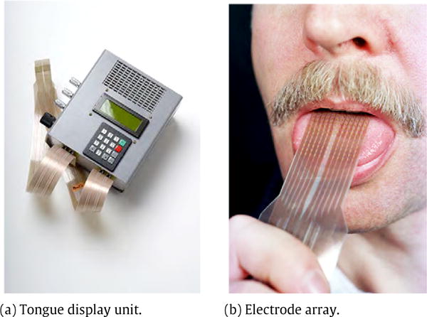
Photo of tongue display unit (a) and electrode array (b). Jeff Miller, University of Wisconsin–Madison, used with permission.
1.1. Electrotactile stimulation
Electrotactile stimulation evokes tactile sensations within the skin at the location of a small, surface electrode, by passing a local electric current through the skin to stimulate cutaneous afferent nerve fibers. The percepts thus produced (vibration, tingle, pressure) can be used to communicate temporal and spatial information that is normally received through other sensory channels, such as vision, audition, proprioception and the vestibular sense [1–6]. Specific applications will be reviewed later in this article.
1.2. Why the tongue?
1.2.1. Sensitivity
The tongue is an ideal site for electrotactile display [7]. It is highly mobile and very sensitive to touch, both in pressure sensitivity and spatial acuity [8–10]. It has a large representation in the brain, rivaling that of the hands, the primary human organ for exploration by touch [11]. The lips, palate and oral mucosa are also very sensitive to touch (with somewhat different sensory properties) and have been explored as sites for electrotactile display [12–16].
1.2.2. Electrical stability
Because of the tongue’s protected location in the mouth, its hydration (and hence its electrical properties) is more consistent than those of the skin. In particular, the impedance of the electrode-tongue interface varies little with current, unlike cutaneous locations, where resistance drops sharply with increasing current [17–20].
Because electrode current rather than voltage is the better indicator of subcutaneous potential distribution and hence afferent nerve depolarization, electrotactile stimulation on the skin normally requires current-controlled (e.g. transconductance amplifier) circuitry [21,22]. On the tongue, however, simpler voltage-control circuitry suffices [23].
2. Theory of operation
This section will first describe the overall architecture of the TDU, followed by a discussion of the output waveform structure and how it activates the tongue cutaneosensory system to produce the desired tactile sensations. Next is a description of the output circuit responsible for delivering these pulses to an electrode array, with maximum simplicity and minimization of possible tissue irritation. Practical limitations of the TDU are described next, along with features enabling the stimulation waveform to be easily monitored. Finally, the TDU modes of operation and provisions for software control are summarized.
2.1. Architecture
The 12 × 12 electrode matrix (described more fully below) is functionally divided into four square, 36-electrode blocks (Figure 2). The electrodes in each block are sequentially pulsed in a raster-scanned format, as described later. The electrode blocks, A–D, dictate the core functional units of the TDU circuitry.
Figure 2.
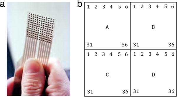
The TDU electrode array (a) is divided into four 36-electrode blocks (A–D), each of which is raster-scanned in synchrony with the other blocks (see text). The bottom of the array in this figure rests approximately 1 cm posteriorly to the tip of the tongue. Jeff Miller, University of Wisconsin–Madison, used with permission.
Figure 3 shows a block diagram of the TDU, which comprises five 8-bit microcontrollers, electrode driver output, power and communications circuits. The four microcontrollers labeled “Block” perform the low-level pulse generation functions for each grouping of 36 electrodes using waveform parameter information delivered from the main microcontroller. The latter handles communications to and from an external computer via an RS-232 serial link and allows for direct user control via a front panel button set and 4-line LCD display. Power is provided by an internal, rechargeable NiMH battery.
Figure 3.
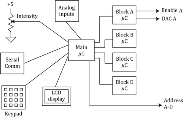
Block diagram of TDU. The main microcontroller (μC) accepts control inputs from an intensity control, keypad and RS-232 serial port. It controls the four block (A–D) microcontrollers, each of which controls pulse timing for one block via the output circuit shown in Figure 5. An LCD display provides status information to the user.
2.2. Output waveform structure
Like most electrotactile systems, the TDU delivers sequences of rectangular pulses with timing features assumed to correspond with relevant neurophysiologic time constants. Because direct experimental data concerning the afferent neural response to tongue electrotactile stimulation are limited, e.g. [24], our comments are extrapolated from the general properties of cutaneous afferent fibers, supplemented by limited experimental data from mechanoreceptive afferents during electrotactile stimulation of primate fingertips [25]. The fundamental neurophysiological bases for specific design decisions must therefore be considered preliminary.
Positive stimulation pulses were chosen following unpublished pilot experiments showing lower sensory thresholds (similarly to [24]) and more comfortable sensory properties compared with negative pulses. (Positive pulses are also preferable on the fingertips, especially when small electrodes are used [26], whereas negative pulses are generally superior on other loci [3].)
The TDU output waveform (Figure 4, Table 1) is a complex train of pulses with two levels of pulse grouping (bursts). This section will consider this structure from smallest to largest time features.
Figure 4.
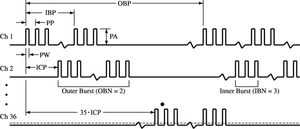
The TDU output waveform includes multiple levels of pulse grouping to achieve the desired tactile sensations (see text). Pulses are grouped into inner bursts, which are further grouped into outer bursts. Pulse amplitude, burst timing, and numerosity are controlled by the following parameters: Outer Burst Period (OBP), Inner Burst Period (IBP), Pulse Period (PP), Pulse Width (PW), Outer Burst Number (OBN), Inner Burst Number (IBN), Inner-Channel Period (ICP), Pulse Width (PW) and Pulse Amplitude (PA). Table 1 defines the operational range for these parameters.
Table 1.
TDU stimulation parameters. Parameter values are controllable in real time, updated at the beginning of each outer burst, within the limits shown in the table.
| Symbol | Name | Range | Resolution | Units | Typical range | Standard waveform |
|---|---|---|---|---|---|---|
| PA | Pulse amplitude | 0–40 | 0.157 | V | 5–20 | Varies per user |
| PW | Pulse width | 0–510 | 2 | μs | 10–100 | 50 |
| IBN | Inner burst number | 0–255 | 1 | pulses | 1–10 | 1 |
| OBN | Outer burst number | 0–255 | 1 | bursts | 1–10 | 3 |
| PP | Pulse period | 2–510 | 2 | μs | 10–100 | n/a |
| IBP | Inner burst period | 0–25.5 | 0.1 | ms | 1–10 | 5 |
| OBP | Outer burst period | 5–1,275 | 5 | ms | 10–1000 | 20 |
| ICP | Inner-channel period | 2–510 | 2 | μs | 138 |
The following additional restrictions ensure the integrity of the burst structure:
PW < PP
PP·IBN < ICP
ICP·35 < IBP
OBN·IBP < OBP.
2.2.1. Pulses and inner bursts
Individual Pulses of Width (PW), repeating with a period (PP), are grouped into inner bursts. The number of pulses in each inner burst is defined as the Inner Burst Number (IBN). Because the neural membrane acts approximately as a leaky integrator (parallel RC network), the charge from individual pulses summates to cause membrane depolarization which, if it exceeds a certain threshold value, causes an action potential to propagate unattenuated toward the spinal cord and brain [27] to effect sensation. The effective time constant of this integrator for human somatosensory fibers has been estimated at 70–900 μs and is dependent not only on membrane properties, but also on fiber orientation and electrode geometry [28, Chaps. 4 and 7].
Given this time dependency, the Pulse Amplitude (PA) voltage, PW and PP all determine whether an individual neuron will be stimulated. Because of the neural membrane’s refractory period during which its sensitivity to re-stimulation is eliminated (approx. 0.5 ms) or elevated (several ms), only one action potential may be produced on a given fiber during each inner burst [28, p. 88]. In this way, these inner burst parameters affect primarily the sensory threshold and perceived intensity of the stimulation.
The neural membrane time constant decreases with increasing fiber diameter. Therefore, longer pulses may preferentially activate the smaller (Aδ, C) fibers subserving pain sensations relative to the tactile-sensation (Aβ) fibers [29]. As a result, both PW and inner burst structure (PP, IBN) may affect not only the intensity, but also the quality of the perceived electrotactile percept [30,31]. The intensity effect, however, is the most noticeable.
2.2.2. Outer bursts
A sequence of inner bursts, repeating with an inner-burst period of IBP, may be grouped into an outer burst. The number of inner bursts in an outer burst is the Outer Burst Number (OBN). While each inner burst results in at most one action potential, the time between inner bursts allows the nerve fiber to recover and therefore each outer burst may cause up to OBN action potentials. Furthermore, this neural activity occurs at a rate similar to that attainable by mechanical tactile stimuli [32]. Manipulating OBN and IBP can change the perceived quality of the electrotactile sensation, as well as its ability to convey spatial information [33–35]. These non-intensive perceptual quality changes have been loosely described as tactile “colors” because they are readily discernible, although not nearly so much as for color vision [33,36]. For example, increasing pulse rate typically results in percept changes from pulsatile to vibration to pressure, whereas pulse width and burst structure can affect the comfort of the percept (vibration/tingle vs. pinprick) [37,38].
2.2.3. Base frequency
Finally, outer bursts may be interrupted by periodic pauses and repeat at the Outer Burst Period (OBP). The reciprocal of OBP is the base frequency of the stimulus waveform and this highest-level structure has a strong influence on one of the perceived qualities of the electrotactile sensation, sometimes called “pitch” in analogy to auditory perception of sinusoidal tone frequency [39,40]. Increasing OBN and 1/OBP also increases spatial pattern perception performance (probably via a sampling rate effect, see [35]), as well as the rate and magnitude of sensory adaptation [41].
2.3. Electrode sequencing
As indicated above, the 144 channels (each channel driving one electrode) are grouped into four 36-channel blocks (Figure 2). Each block drives one 6 × 6 region of the electrode array. The electrodes in each block are raster scanned in horizontal lines from left to right, top to bottom, as shown in Figure 2; on the tongue this corresponds to left-to-right, posterior to anterior. The onset of outer burst sequences between temporally-adjacent electrodes is the delay parameter ICP, for an inner-channel period (Figure 4). (Although ICP is technically not a period, we retain this nomenclature to be consistent with the software command set.) An inner burst on a given electrode must be complete before the temporally-adjacent electrode may begin its next inner burst. The beginning of the outer bursts in the four blocks is synchronized, so that four electrodes on the 12 × 12 array may be active at any time.
Only one electrode per block may be active at any time. The raster-scanning structure ensures that active electrodes are separated by 5 electrode center–center spaces, or approximately 11.6 mm, using the default electrode array. This separation allows unstimulated electrodes to act as the return current path (see the output circuit description, in Section 2.5). It is important to not have spatially-adjacent electrodes simultaneously active, because (1) there would then be an interrupted effective return path, potentially spreading the tactile sensation, and (2) the currents in the adjacent electrodes partially summate, yielding an abnormally strong tactile sensation. These comments result from unpublished pilot experiments; this is an area ripe for more extensive study.
There is a question whether raster scanning is the most effective pattern for static or dynamic spatial pattern perception. We did not test other scanning patterns on the tongue. We previously performed a preliminary experiment (unpublished) using four scan patterns (horizontal raster lines similarly to the TDU, vertical raster lines and two random scan patterns) on a 7 ×7 fingertip-explorable electrotactile array we tested earlier [35,42]. The subjects tested did not show any differences in static pattern perception, even for directional patterns (e.g. lines and arrows) that would most likely be affected by scan pattern. Dynamic patterns were not tested.
All waveform parameters in Figure 4 are manipulable via software commands to the TDU; new values become effective at the beginning of the first outer burst following the command. PA, PW, IBN and OBN may be set individually for each electrode. The burst timing parameters PP, IBP, OBP and ICP are common to all electrodes in the array.
Note that the present waveform timing nomenclature is different from that previously used by the author [21], in order to allow for more control over burst structure. Some of the terms are comparable, these being (new = old): PW = W, ICP = D, IBP = P, OBP = T, OBN = NPB. IBN and PP have no equivalents in the old nomenclature.
2.4. TDU timing limits
Table 1 shows the allowable timing and voltage values of TDU output pulses. This table also shows typical ranges, as well as a “standard” waveform which yields comfortable electrotactile sensations over a wide range of pulse amplitudes. This waveform was developed according to a magnitude-based dynamic range methodology previously reported [37]. Even if the parameters are within equipment limits, certain conditions apply to prevent corrupting the waveform burst structure. These limits, which appear in the Table 1 legend, are enforced by the TDU microcode.
2.5. Output circuit
Figure 5 shows (for one block of 36 channels) the essentials of the TDU output circuit, which controls the voltage and timing of the rectangular pulses sent to the electrode array. TDU output voltage is set by a Digital-to-Analog Converter (DAC) feeding an operational amplifier (OpAmp) buffer (U1). The output of U1 is directed to the appropriate output channel by an analog switch (U2). The Address lines feeding U2 choose which channel to pulse, while the Enable line determines the pulse and burst timing. Activity in these lines, along with the DAC, is synchronized by the μC, so that when a given channel is due to be active (i.e. receive a pulse), the correct voltage is delivered and the correct electrode is selected. The four TDU output blocks are controlled similarly (and synchronously), each block having its own DAC, buffer and analog switch. This hybrid analog-digital architecture results in fast switching of the variable-amplitude output pulses, while relaxing the speed and data-handling requirements of the DAC, a solution employed by other electrotactile researchers [43,44]. Described next are functions of the passive components in this circuit that manage the electrical characteristics of the output, performance limitations imposed by this architecture, and provisions for monitoring the TDU output in real time.
Figure 5.
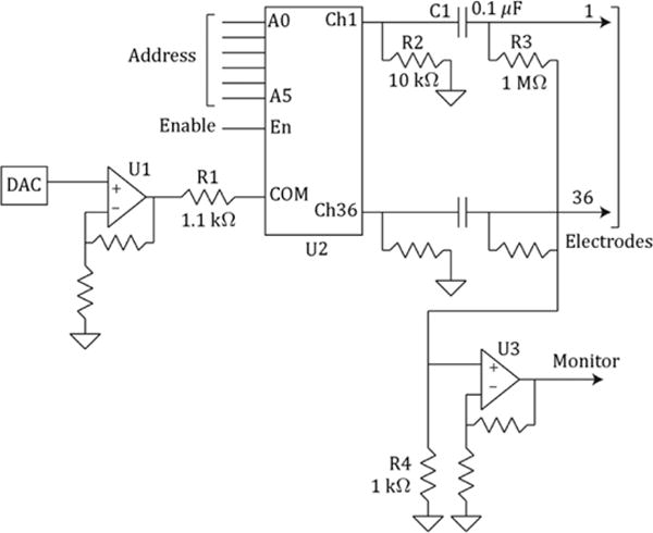
The TDU output circuit (one block shown) contains circuitry to control pulse amplitude (DAC and U1), active output resistance (R1), passive output resistance (R2), dc suppression (C1), dc stabilization (R3), and external monitoring (R3, R4, U3); see text. The analog multiplexer U2 controls pulse timing according to logic pulses on the address and enable lines; these signals are produced by the microcontroller for each block (Figure 3).
2.5.1. Passive components
The output circuit incorporates several features for controlling output resistance, providing a return path for the active electrode, and minimizing tongue tissue irritation. The output resistance for the active electrode is controlled primarily by R1 (the “on” resistance of U2 is ≤ 100 Ω). This 1.2 kΩ total resistance limits the current through U1 and U2 to prevent circuit damage should a short-circuit load be connected. It also provides a good quality of sensation over a variety of electrode sizes, although previous research [23] suggests that output resistance may not be critical in this matter.
Series capacitor C1 slightly shifts the mean output voltage so that the net dc current into the tongue electrode is extremely small. This minimizes the possibility of extracellular ion migration and electrochemical reactions that might cause tissue irritation. A separate capacitor C1 is used for each electrode so that dc balance is achieved for each electrode, even if the electrodes receive different voltages or waveforms. Note that the average TDU output (and therefore electrode) current is exactly zero with this circuit only if the electrode-tongue resistance is linear, because of the unbalanced pulse structure. Nonlinear resistive loads exhibit a “rectification effect” when driven with unbalanced waveforms [45]. For a discussion of this effect in the context of electrotactile stimulation and its possible relationship with skin or tissue irritation, see [19, Chap. 8]. Fortunately, the electrode-tongue interface resistance is relatively independent of current. In ten years of use in various experiments using approximately 200 human subjects (under protocol and oversight approved by the University of Wisconsin–Madison Health Sciences Institutional Review Board), none have reported tongue irritation. Prospective studies on the long-term effects of electrotactile tongue stimulation have not yet been performed.
The value of C1 (0.1 μF) represents a compromise between minimizing dV/dt voltage droop during stimulation pulses (a larger capacitance reduces droop; see Section 2.5.2.) and limiting the maximal delivered pulsatile charge to a safe level (4 μC) should a circuit failure occur [22]. This pulse charge is much less than the 290 μC upper limit recommended by Underwriters Laboratories (UL), a recognized electrical-safety certification organization. (The TDU itself has not been certified by UL or any other regulatory agency.)
Parallel resistor R2 serves as the primary sink for current returning to the TDU via the inactive electrodes. Because U2 disconnects inactive electrodes from U1 and R1, the effective TDU “output” resistance (assuming minimal drop in output capacitors C1) for the return current is 10 kΩ for each inactive channel. Adding to this the approximate electrode resistance of 6 kΩ per electrode (see later), the return-current resistance for each inactive electrode is 16 kΩ. Because the actual return path comprises a parallel combination of 35 TDU-electrode series-connected networks, the overall return resistance is approximately (16 kΩ)/35 = 457 Ω.
Parallel resistor R3 ensures a stable dc operating point (i.e. forces the mean output voltage to zero) even if the electrode is disconnected; its high value ensures that it has minimal effect on pulse voltage.
2.5.2. Performance limitations
The actual electrode voltage is somewhat less than that commanded by the software (by specification, 0–40 V) for three reasons: (1) There is a voltage drop across R1 of approximately 17% (once the exponential rise phase caused by electrode capacitance is over) due to voltage division, assuming a 6 kΩ tongue load and 1.2 kΩ TDU output resistance. (2) The presence of C1 slightly reduces the mean pulse voltage; the fraction of reduction is (1-Duty), where Duty = PW·OBN·IBN/OBP. For a typical stimulation waveform (PW = 50 μs,·OBN = 3, IBN = 1, OBP = 20 ms), duty is < 1%, so this pulse level reduction is minimal. (3) The nonzero return-path resistance reduces the effective voltage at the electrode-tongue interface, i.e. between the active electrode and the underlying large volume conductor (i.e. below the surface of the tongue; this “central” tongue voltage will be similar to the mean whole-body voltage, assuming no possible current pathways other than the tongue). Note that while effects (1)–(2) represent reductions in the TDU output voltage and may be measured relative to the TDU ground, effect (3) represents a voltage difference between the body and the TDU ground and will not be reflected by measuring the output relative to the TDU ground. Fortunately, all three effects on a percentage basis remain relatively constant with changes in electrode voltage (because of the stable electrode-tongue resistance) and also with waveform timing (because of the small effect of the duty cycle). Nevertheless, the TDU user should be aware that the output voltage and pulse shape may be different from those expected and if in doubt measure these waveforms directly.
2.5.3. Measurement features
A voltage monitor circuit (one per block) is provided so that the user may observe (e.g. on an oscilloscope) the actual voltage delivered to the electrodes, which is recommended practice given the effects described in the above paragraph (only effects (1)–(2) are monitored). An OpAmp buffer (U3) amplifies the small voltage across R4 resulting from currents flowing through resistors R3. The buffer output (Monitor) waveform sequentially shows the (scaled) sum voltage of all electrodes in the block. Because the electrodes are pulsed individually, it is possible to separately measure the voltage on any given electrode while it is active. The small value of R4 relative to R3 ensures that there is minimal crosstalk between channels, owing to the small potential appearing at the R3–R4 junction.
Finally, the TDU provides a logic-level synchronization output, which delivers a brief pulse at the beginning of each outer burst. This is useful for synchronizing external devices such as an oscilloscope.
It should be noted that the manner of connecting any external measurement instruments to the TDU should be evaluated for their impact on the overall safety of the system, for example by introducing ground faults or alternative current pathways. The TDU external connectors (power, data, electrode and monitor connectors) share a common electrical ground. Appropriate external isolation should be introduced, as needed, to ensure the safety of users and human subjects, depending on the particular experimental application. The TDU itself may be operated using its internal battery for 2–3 h, eliminating the need for external power for that period of time.
2.6. Modes of operation and external control
The TDU may be used either as a standalone device or may be controlled by an external computer, depending on the particular needs of the user. It therefore has three modes of operation selectable by top panel controls: Standalone, Remote, and Update Pattern. TDU electrotactile stimulation is defined by the active pattern, which is the set of waveform parameters defined above in Section 2.2. The active pattern may be defined in real time via software commands (below), or may be set to one of 53 pre-programmed patterns in the TDU’s non-volatile memory. Only one pattern is active at any given time.
Standalone mode allows the user to control, via a top panel keypad, which of the 53 static pre-programmed patterns is displayed (i.e. made active). The side knob adjusts overall pattern intensity (voltage). Serial communications and auxiliary analog inputs (1–5), accessible on the side panel, are disabled in standalone mode.
Remote mode enables a command interpreter in the Main microcontroller, which allows an external computer to control all TDU functions except power and mode. The command set includes functions to turn electrode stimulation on and off and control its overall level, based on the side panel knob position (which may also be disabled). It is also possible to modify all waveform parameters in real time for the active pattern (see Section 2.2), which may be either a pre-programmed pattern or a completely custom pattern. Remote mode allows the parameters of the active pattern to be sent back to the external computer. In remote mode, the top panel controls are disabled, but all the analog inputs are readable, including the one to which the side panel knob is connected.
Update pattern mode only allows pre-programmed patterns to be updated or queried via the serial port. Tactile stimulation is disabled in this mode.
3. Tongue electrodes
Although the TDU may be used (within its voltage and pulse timing limits) with any kind of stimulation electrodes, we have developed a particular geometry which is convenient and yields comfortable and controllable electrotactile sensations (Figure 2). This array, fabricated by a commercial flexible printed circuit vendor, is a 12 × 12 square matrix mapped to the TDU output connectors via an insulated flex circuit strip. Each of the electrodes is 1.55 mm diameter and the center–center spacing is 2.32 mm. The overall dimension of the array is therefore 27 × 27 mm, which fits comfortably on the tongue with the flexible strip exiting the mouth and held gently between the teeth or lips. The exposed electrodes are gold-plated surface copper pads. This gold layer, which is included to minimize electrochemical reactions at the tongue, is deposited using an “electroless” (chemical, not electrochemical) process and is very thin, and degrades with prolonged use (hundreds of hours). A thicker electroplated layer for longer life is being explored.
3.1. Electrical properties
Figure 6 shows typical measured voltage and current on one TDU electrode near the center of the array. The electrical properties of the electrode-tongue interface have not been studied in detail. Preliminary measurements show that for the above geometry, an electrode in firm but comfortable contact with the tongue presents a resistive component of approx. 1 kΩ, in series with a resistive-capacitive network of 4–6 kΩ in parallel with 0.5 nF. These values depend on electrode diameter; a larger electrode reduces resistance and increases capacitance. If the electrode does not firmly contact the tongue, the resistance may drop by several times, due to saliva becoming the primary current pathway.
Figure 6.
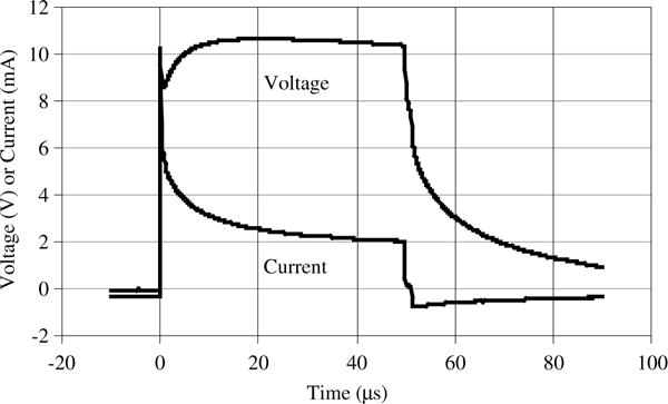
Typical TDU measured waveform. Captured using a Tektronix A6312 current probe and AM503B current probe amplifier, and an Agilent DSO6034A digital oscilloscope. Spike at beginning of waveform is current trace due to electrode-tongue interface capacitive component (see text). The electrode array in Figure 2 was used; electrode diameter is 1.55 mm.
The above electrode size and spacing limit the density of spatial information that may be displayed. The tactile resolution of the tongue is in the order of 0.6 mm [9], suggesting that more dense arrays might be successfully employed. However, smaller electrodes degrade the quality of the electrotactile sensation, which acquires more of a “stinging” quality as electrode size decreases [23]. Research is necessary to determine whether this tradeoff may be at least partially mitigated by using different stimulation paradigms, e.g. by the use of depolarizing per-pulses [46].
3.2. Practical considerations
3.2.1. Threshold variations
Because electrodes at the array periphery are not fully surrounded by additional electrodes that are able to serve as return current paths, the electric potential distribution in the tongue may be different near these electrodes, compared with electrodes more centrally located on the array. This asymmetry however does not appear to result in different sensitivity to tongue stimulation at the array edge, according to unpublished pilot experiments similar to [47]. The published study showed, however, that there are gradual threshold variations across the surface of the tongue that are not localized to the edge of the electrode array. In particular, the lowest thresholds were observed anteriorly and medially (near the tip, which has the highest density of nerve endings) compared with more posterior and lateral regions. Practical applications may need to take into consideration these sensitivity differences and make appropriate compensations, as necessary.
3.2.2. Active vs. passive
The tongue may rest in a fixed position on the tongue, or may actively scan the surface, depending on the particular application. Scanning the array using the tip of the tongue affords higher resolution (due to the higher density of tactile nerve endings in the tip of the tongue) and more control over information acquisition, at the expense of a smaller “field of view”, similarly to fingertip-scanned tactile displays [35]. Even if the tongue has a fixed position on the array, it may be possible for the user to indirectly control the display of information on the electrode, for example, by manipulating the camera in a tactile vision system [3].
4. Selected applications
Approximately 15 TDUs have been built and used in various collaborative research projects at the University of Wisconsin–Madison and in other laboratories in the USA, France, Canada and Mexico. The TDU has not been offered for sale commercially. Tongue-based electrotactile display, using the TDU, has been investigated for several practical applications in sensory substitution and neurorehabilitation. Over one hundred potential applications in the realm of sensory systems, communications, human–machine interfaces, and neurorehabilitation have been identified; selected applications will be detailed below.
General theory and application of electrotactile stimulation have been reviewed elsewhere [28,30,31,48–50]. Extensive reviews of tactile-based information display and sensory substitution may be found in [1–6,51]. There are additional reviews specifically concerning tactile substitution of vision [52–54], audition [55–58], from specialized sensors that monitor the status of prosthetic devices [59–61], and from teleoperators and virtual environments [62].
4.1. Vision substitution
Tactile Vision Substitution (TVS) was the initial motivation for designing the TDU. With TVS, a user-controlled video camera captures a real-time image from the ambient environment and provides a spatially-corresponding tactile stimulation to the user’s skin. Based on the tactile sensation where, for example, regions of strong tactile stimulation might correspond to light areas of the camera image, users are able to perform visual tasks such as reading text, object identification and localization, hand-“eye” coordination (e.g. catching a ball), and obstacle avoidance while walking [52,63–65].
4.1.1. Tongue
TVS Many of these early results with TVS systems utilizing tactile displays on the abdomen or back have been replicated using tongue-based TVS [1,2]. Specific behavioral studies published include an estimation of tongue-TVS visual acuity using the TDU [66], and using the BrainPort™ Vision Device (Wicab, Inc., Middleton, WI, USA), a commercial tongue-based electrotactile sensory substitution device based on operational principles pioneered by the TDU [67]. Navigation of a human-controlled robot, while receiving visual information from a robot-mounted camera, and displayed on the tongue using the TDU, has also been reported [68]. Interestingly, the concept of tongue TVS was independently proposed in 1920 [69] and 1999 [70], but apparently never implemented until the TDU-based system.
4.1.2. TVS neuroplasticity
Visual-tactile brain plasticity, in which the visual cortex shows activity attributable to tongue-TVS use, has been demonstrated using positron electron tomography [71,72]. As also shown for blind Braille readers [73], experienced blind tongue-TVS users experience tongue tactile sensations in response to transcranial magnetic stimulation of the occipital cortex [74], indicating bi-directional plasticity between the tongue somatosensory and visual systems.
4.2. Balance substitution
Tactile substitution of balance information has been used to provide cues of head tilt for persons with disorders of the balance organs in the inner ear due to drug reactions, trauma, or conditions such as Meniere’s disease. Individuals lacking any clinically-discernible vestibular function (bilateral vestibular deficit) show immediate improvement in postural stability while using a TDU, which in this case displays head tilt as the position of a small spot of electrotactile stimulation on the tongue [75]. Such improvements persist for hours to weeks and often longer, even after the device is removed from the mouth, depending on the cumulative time the subject has used the system (typical usage is two half-hour sessions per day).
This method has been commercialized as the BrainPort™ Balance Device (Wicab, Inc.), which has been extensively tested by the investigators [76] and by independent researchers [77, 78]. Earlier attempts to improve balance via non-tongue sensory substitution systems have shown immediate improvement, but no long-term beneficial effect [79,80]. Finally, TDU and TDU-like research devices have also been shown to reduce postural sway resulting from Achilles tendon vibration [81], neck extension [82] and fatigued trunk muscles [83]. In the latter two citations, plantar pressure, rather than head tilt, was measured by a force plate and was used to control the tongue stimulus.
4.3. Induced neuroplasticity
It has recently been shown that the presumed neuroplastic changes responsible for the long-term benefits of TDU-based vestibular substitution may be realized without the informational component. TDU or TDU-like tongue stimulation delivered simultaneously with balance and gait exercises, even if the tongue stimulus is not linked to head, plantar or any other kinds of sensor, appears to yield both long-term symptom reduction as well as measureable changes in brain activity [84–90,100,101]. This new method, which is not sensory substitution, but which may, if desired, be combined with sensory substitution, has been dubbed Cranial-Nerve Non-Invasive Neuromodulation (CN-NINM) and is under investigation at the Tactile Communication and Neurorehabilitation Lab (TCNL) at the University of Wisconsin–Madison.
4.4. Augmentative information display
Coded tongue-tactile signals have also been proposed and demonstrated to enhance situational awareness, mobility and dexterity for persons engaged in delicate, high-risk, covert, and/or visually-obstructed tasks [1,91–93]. For example, guidance of a surgical tool manipulation has been demonstrated using only TDU-based feedback [94], and tactile feedback from robots to assist spinal cord injuries has been proposed [95], along with tactile feedback of seated pressure, to prevent pressure sores [96] and to gain greater awareness of ankle joint rotation in a fatigued state [97]. The TDU as a platform technology allows virtually any kind of information to be presented to the tongue, subject to the human limits of electrotactile perception on the tongue, which are just beginning to be explored [98].
5. Disclosure
Tongue-tactile-display technology is patented in the USA and other countries by the Wisconsin Alumni Research Foundation [99], from which the author receives royalty payments. The author also has an ownership interest in Advanced NeuroRehabilitation, LLC (Madison, WI, USA), a company formed to develop and commercialize non-invasive neuromodulation technology. The TDU itself has not been commercialized.
Acknowledgments
This work was supported by the National Eye Institute (grant R01-EY10019) and the Charles E. Culpeper Foundation (grant 921162). It was also supported by the University of Wisconsin Robert Draper Technical Innovation Fund (project numbers 981517, 991000), and Industrial and Economic Development Research Fund.
The author acknowledges the technical assistance of Mar-wan E.A. Estiban for detailed circuit and software design, Mitchell E. Tyler for development of the user interface, and both Tyler and Yuri P. Danilov for development and testing of sensory substitution and neurorehabilitation applications using the TDU.
The author also acknowledges John G. Webster who, as the author’s former academic advisor, encouraged actually building devices and testing ideas instead of only thinking about them. This article is dedicated to the late Paul Bach-y-Rita, pioneer in brain plasticity, rehabilitation, and sensory substitution who, in 1998, challenged the author to explore electrotactile stimulation on the tongue.
Finally, helpful advice from the anonymous manuscript reviewers is gratefully acknowledged.
Biography
Kurt Alan Kaczmarek (M’86-SM’05) received a B.S. degree from the University of Illinois, Urbana, in 1982, and M.S. and Ph.D. degrees from the University of Wisconsin–Madison, Madison, in 1984 and 1991, respectively, all in Electrical Engineering. From 1984 to 1986, he was Senior Engineer with Baxter International, Deerfield, IL. He is currently Senior Scientist at the University of Wisconsin, Madison, where, since 1992, he has been studying the mechanisms and perception of electrical stimulation of touch. His current research interests include tactile displays, sensory rehabilitation and augmentation, teleoperation and neurorehabilitation.
References
- 1.Bach-y-Rita P, et al. Seeing with the brain. Int J Hum-Comput Interact. 2003;15:285–295. [Google Scholar]
- 2.Bach-y-Rita P, Kercel SW. Sensory substitution and the human–machine interface. Trends Cogn Sci. 2003;7:541–546. doi: 10.1016/j.tics.2003.10.013. [DOI] [PubMed] [Google Scholar]
- 3.Kaczmarek KA, Bach-y-Rita P. Tactile displays. In: Barfield W, et al., editors. Virtual Environments and Advanced Interface Design. Oxford University Press; New York: 1995. pp. 349–414. [Google Scholar]
- 4.Loomis JM. Sensory replacement and sensory substitution: overview and prospects for the future. In: Roco MC, et al., editors. Converging Technologies for Improving Human Performance: Nanotechnology, Biotechnology, Information Technology and Cognitive Science. Kluwer Academic; Boston: 2003. [Google Scholar]
- 5.Tyler ME. Tactile devices and perception. In: Vanderheiden GC, editor. Handbook on State-of-the-Art Technology: Proceedings of the Sixth International Conference on Computer Aids for the Visually Impaired. Trace R&D Center, University of Wisconsin; Madison, WI: 1990. [Google Scholar]
- 6.Visell Y. Tactile sensory substitution: models for enaction in HCI. Interact Comput. 2009;21:38–53. (special issue: enactive interfaces) [Google Scholar]
- 7.Bach-y-Rita P, et al. Form perception with a 49-point electrotactile stimulus array on the tongue: a technical note. J Rehabil Res Dev. 1998;35:427–430. [PubMed] [Google Scholar]
- 8.Pufall HE. PhD Thesis. University of Southern California; 1970. A normative study of oral sensation and perception: two-point discrimination, form identification, tactile pattern recognition, and mandibular kinesthesia. [Google Scholar]
- 9.Van Boven RW, Johnson KO. The limit of tactile spatial resolution in humans: grating orientation discrimination at the lip, tongue, and finger. Neurology. 1994;44:2361–2366. doi: 10.1212/wnl.44.12.2361. [DOI] [PubMed] [Google Scholar]
- 10.Weinstein S. Intensive and extensive aspects of tactile sensitivity as a function of body part, sex and laterality. In: Kenshalo DR, editor. The Skin Senses. Charles C. Thomas; Springfield, IL: 1968. pp. 195–218. [Google Scholar]
- 11.Kandel ER. From nerve cells to cognition: the internal cellular representation required for perception and action. In: Kandel ER, editor. Principles of Neural Science. 4th. McGraw-Hill; New York: 2000. pp. 381–403. [Google Scholar]
- 12.Agarwal AK, et al. Two-way communication through an oral-based tactile interface: preliminary results. Proc Annu Conf IEEE Eng Med Biol Soc. 2001 [Google Scholar]
- 13.Kim D, et al. Two-way communication through an oral-based tactile interface: preliminary results, Annual Report of the Research Reactor Institute. Kyoto University. 2001;2:1468–1471. [Google Scholar]
- 14.Ostrom NP, et al. 21st Annu Conf IEEE Eng Med Biol Soc. IEEE; Atlanta, Georgia, USA: 1999. A microfabricated electrocutaneous tactile display; p. 838. [Google Scholar]
- 15.Tang H, Beebe DJ. Proc First Joint BMES/EMBS Conf. IEEE; Atlanta, GA, USA: 1999. An ultra-flexible electrotactile display for the roof of the mouth; p. 626. [Google Scholar]
- 16.Tang H, Beebe DJ. Proc 1st Int IEEE-EMBS Special Topic Conf Microtech Eng Med Biol. IEEE; Lyon, France: 2000. An oral tactile interface for two-way communication; pp. 639–643. [Google Scholar]
- 17.Boxtel AV. Skin resistance during square-wave electrical pulses of 1–10 mA. Med Biol Eng Comput. 1977;15:679–687. doi: 10.1007/BF02457927. [DOI] [PubMed] [Google Scholar]
- 18.Kaczmarek KA, Webster JG. Voltage–current characteristics of the electrotactile skin-electrode interface. In: Kim Y, et al., editors. Proc Annu Int Conf IEEE Eng Med Biol Soc. Vol. 11. IEEE; Seattle, WA: 1989. pp. 1526–1527. [Google Scholar]
- 19.Kaczmarek KA. PhD Thesis. Dept Electrical and Computer Engineering, Univ of Wisconsin–Madison; 1991. Optimal electrotactile stimulation waveforms for human information display. [Google Scholar]
- 20.Square-wave analysis of skin impedance. Lykken DT, editor. Psychophysi-ology. 1971;7:262–275. doi: 10.1111/j.1469-8986.1970.tb02232.x. [DOI] [PubMed] [Google Scholar]
- 21.Kaczmarek KA, et al. A 16-channel 8-parameter waveform electrotac-tile stimulation system. IEEE Trans Biomed Eng. 1991;38:933–943. doi: 10.1109/10.88439. [DOI] [PubMed] [Google Scholar]
- 22.Schaning MA, Kaczmarek KA. A high-voltage bipolar transconduc-tance amplifier for electrotactile stimulation. IEEE Trans Biomed Eng. 2008;55:2433–2443. doi: 10.1109/TBME.2008.926675. [DOI] [PMC free article] [PubMed] [Google Scholar]
- 23.Kaczmarek KA, Tyler ME. Proc ASME Dyn Sys Contr Div. 2. Vol. 69. Orlando, Florida: DSC; 2000. Effect of electrode geometry and intensity control method on comfort of electrotactile stimulation on the tongue; pp. 1239–1243. ASME. [Google Scholar]
- 24.Bujas Z, Mayer D. Sensory effects of continuous and iterative electrical stimulation of the tongue. Acta Inst Psychol Univ Zagrabiensis. 1977;79(86):35–50. [Google Scholar]
- 25.Kaczmarek KA, et al. The afferent neural response to electrotactile stimuli: preliminary results. IEEE Trans Rehabil Eng. 2000;8:268–270. doi: 10.1109/86.847828. [DOI] [PubMed] [Google Scholar]
- 26.Poletto CJ. PhD Thesis. Case Western Reserve University; 2000. Fingertip electrocutaneous stimulation through small electrodes. [Google Scholar]
- 27.Schmidt RF, editor. Fundamentals of Sensory Physiology. Springer-Verlag; New York: 1986. [Google Scholar]
- 28.Reilly JP. Applied Bioelectricity. Springer; New York: 1998. [Google Scholar]
- 29.Grill WM, Mortimer JT. Stimulus waveforms for selective neural stimulation. IEEE Eng Med Biol Mag. 1995;14(4):375–385. [Google Scholar]
- 30.Gibson RH. Electrical stimulation of pain and touch. In: Kenshalo DR, editor. The Skin Senses. Charles C. Thomas; Springfield, IL: 1968. pp. 223–261. [Google Scholar]
- 31.Rollman GB. Electrocutaneous stimulation. In: Geldard FA, editor. Proc Conf Cutan Comm Sys Dev. Psychonomic Society; 1973. pp. 38–51. [Google Scholar]
- 32.Talbot WH, et al. The sense of flutter-vibration: comparison of the human capacity with response patterns of mechanoreceptive afferents from the monkey hand. J Neurophysiol. 1968;31:301–334. doi: 10.1152/jn.1968.31.2.301. [DOI] [PubMed] [Google Scholar]
- 33.Aiello GL. Multidimensional electrocutaneous stimulation. IEEE Trans Rehabil Eng. 1998;6:95–101. doi: 10.1109/86.662625. [DOI] [PubMed] [Google Scholar]
- 34.Haase SJ, Kaczmarek KA. Electrotactile perception of scatterplots on the fingertips and abdomen. Med Biol Eng Comput. 2005;43:283–289. doi: 10.1007/BF02345967. [DOI] [PubMed] [Google Scholar]
- 35.Kaczmarek KA, Haase SJ. Pattern identification and perceived stimulus quality as a function of stimulation waveform on a fingertip-scanned electrotactile display. IEEE Trans Neural Syst Rehabil Eng. 2003;11:9–16. doi: 10.1109/TNSRE.2003.810421. [DOI] [PubMed] [Google Scholar]
- 36.Kajimoto H, et al. Electrocutaneous display with receptor selective stimulations. Trans IEICE. 2001:120–128. J84-D-2. [Google Scholar]
- 37.Kaczmarek KA, et al. Maximal dynamic range electrotactile stimulation waveforms. IEEE Trans Biomed Eng. 1992;39:701–715. doi: 10.1109/10.142645. [DOI] [PubMed] [Google Scholar]
- 38.Saunders FA. Electrocutaneous displays. In: Geldard FA, editor. Proc Conf Cutan Comm Sys Dev. Psychonomic Society; 1973. pp. 20–26. [Google Scholar]
- 39.Szeto AYJ. Relationship between pulse rate and pulse width for a constant-intensity level of electrocutaneous stimulation. Ann Biomed Eng. 1985;13:373–383. doi: 10.1007/BF02407767. [DOI] [PubMed] [Google Scholar]
- 40.Van Doren C. Contours of equal perceived amplitude and equal perceived frequency for electrocutaneous stimuli. Percept Psychophys. 1997;59:613–622. doi: 10.3758/bf03211869. [DOI] [PubMed] [Google Scholar]
- 41.Kaczmarek KA. Electrotactile adaptation on the abdomen: preliminary results. IEEE Trans Rehabil Eng. 2000;8:499–505. doi: 10.1109/86.895953. [DOI] [PubMed] [Google Scholar]
- 42.Kaczmarek KA, Haase SJ. Pattern identification as a function of stimulation current on a fingertip-scanned electrotactile display. IEEE Trans Neural Syst Rehabil Eng. 2003;11:269–275. doi: 10.1109/TNSRE.2003.816874. [DOI] [PubMed] [Google Scholar]
- 43.Poletto CJ, Van Doren CL. A high voltage, constant current stimulator for electrocutaneous stimulation through small electrodes. IEEE Trans Biomed Eng. 1999;46:929–936. doi: 10.1109/10.775402. [DOI] [PubMed] [Google Scholar]
- 44.Takahashi H, et al. Int Conf. Artificial Reality Telexistence (ICAT), Virtual Reality Society of Japan; Tokyo: 2002. Electro-tactile display with localized high-speed switching. [Google Scholar]
- 45.Bridges JE. Pseudo-rectification and detection by simple bilateral nonlinear resistors. Proc IRE. 1961;49:469–478. [Google Scholar]
- 46.Poletto CJ, Van Doren CL. Elevating pain thresholds in humans using depolarizing prepulses. IEEE Trans Biomed Eng. 2002;49:1221–1224. doi: 10.1109/TBME.2002.803563. [DOI] [PubMed] [Google Scholar]
- 47.Tyler ME, et al. Proc IEEE Eng Med Biol Soc. Minneapolis, MN: 2009. Spatial mapping of electrotactile sensation threshold and intensity range on the human tongue: initial results; pp. 559–562. [DOI] [PubMed] [Google Scholar]
- 48.Kaczmarek KA, et al. Electrotactile and vibrotactile displays for sensory substitution systems. IEEE Trans Biomed Eng. 1991;38:1–16. doi: 10.1109/10.68204. [DOI] [PubMed] [Google Scholar]
- 49.Szeto AYJ, Saunders FA. Electrocutaneous stimulation for sensory communication in rehabilitation engineering. IEEE Trans Biomed Eng. 1982:300–308. BME-29. [PubMed] [Google Scholar]
- 50.Szeto AYJ, Riso RR. Sensory feedback using electrical stimulation of the tactile sense. In: Smith RV, et al., editors. Rehabilitation Engineering. CRC Press; Boca Raton, FL: 1990. pp. 29–78. [Google Scholar]
- 51.Sherrick CE, Cholewiak RW. Cutaneous sensitivity. In: Boff KR, et al., editors. Handbook of Perception and Human Performance; Sensory Processes and Perception. Vol. 1. Wiley; New York: 1986. pp. 12.1–12.58. [Google Scholar]
- 52.Collins CC. On mobility aids for the blind. In: Warren DH, et al., editors. Electronic Spatial Sensing for the Blind. Matinus Nijhoff; Dordrecht, The Netherlands: 1985. pp. 35–64. [Google Scholar]
- 53.Easton RD. Inherent problems of attempts to apply sonar and vibrotactile sensory aid technology to the perceptual needs of the blind. Optom Vis Sci. 1992;69:3–14. doi: 10.1097/00006324-199201000-00002. [DOI] [PubMed] [Google Scholar]
- 54.Peli E. Difficulties and roadblocks in applications of hi-tech to low vision. Optom Vis Sci. 1992;69:1–2. [Google Scholar]
- 55.Reed CM, et al. Research on tactile communication of speech: a review. AHSA Monogr. 1982;20:1–23. [PubMed] [Google Scholar]
- 56.Sherrick CE. Basic and applied research on tactile aids for deaf people: progress and prospects. J Acoust Soc Am. 1984;75:1325–1342. [Google Scholar]
- 57.Szeto AYJ, Christensen KM. Technological devices for deaf-blind children: needs and potential impact. IEEE Eng Med Biol Mag. 1988;7(3):25–29. doi: 10.1109/51.7931. [DOI] [PubMed] [Google Scholar]
- 58.Rakowski K, et al. Evaluation of a 32-channel electrotactile vocoder (Abstract) J Acoust Soc Am. 1989;86(Suppl 1):S83. [Google Scholar]
- 59.Collins CC, Madey JMJ. Tactile sensory replacement. Proc San Diego Biomed Symp. 1974;13:15–26. [Google Scholar]
- 60.Phillips CA. Sensory feedback control of upper- and lower-extremity motor prostheses. CRC Crit Rev Bioeng. 1988;16:105–140. [PubMed] [Google Scholar]
- 61.Riso RR. Sensory augmentation for enhanced control of FNS systems. In: Mital A, editor. Ergonomics in Rehabilitation. Taylor and Francis; New York: 1988. pp. 253–271. [Google Scholar]
- 62.Burdea G. Force and Touch Feedback for Virtual Reality. Wiley; New York: 1996. [Google Scholar]
- 63.Bach-y-Rita P, et al. Vision substitution by tactile image projection. Nature. 1969;221:963–964. doi: 10.1038/221963a0. [DOI] [PubMed] [Google Scholar]
- 64.Bach-y-Rita P. Brain Mechanisms in Sensory Substitution. Academic; New York: 1972. [Google Scholar]
- 65.Collins CC, Saunders FA. Pictorial display by direct electrical stimulation of the skin. J Biomed Sys. 1970;1:3–16. [Google Scholar]
- 66.Sampaio E, et al. Brain plasticity: visual acuity of blind persons via the tongue. Brain Res. 2001;908:204–207. doi: 10.1016/s0006-8993(01)02667-1. [DOI] [PubMed] [Google Scholar]
- 67.Chebat DR, et al. Tactile-‘visual’ acuity of the tongue in early blind individuals. NeuroReport. 2007;18:1901–1904. doi: 10.1097/WNR.0b013e3282f2a63. [DOI] [PubMed] [Google Scholar]
- 68.Segond H, et al. Human spatial navigation in a visuo-tactile sensory substitution system. Perception. 2005;34:1231–1249. doi: 10.1068/p3409. [DOI] [PubMed] [Google Scholar]
- 69.Machts L. Device for converting light effects into effects perceptible by blind persons. 326283. Germany: Patent. 1920
- 70.Schimmelpfennig W. Method and apparatus for image recognition for blind and severely visually handicapped persons. 5,878,154. USA: Patent. 1999
- 71.Kupers R, Ptito M. Seeing through the tongue: cross-modal plasticity in the congenitally blind. Int Congr Ser. 2004;1270:79–84. [Google Scholar]
- 72.Ptito M, et al. Cross-modal plasticity revealed by electrotactile stimulation of the tongue in the congenitally blind. Brain. 2005;128:606–614. doi: 10.1093/brain/awh380. [DOI] [PubMed] [Google Scholar]
- 73.Ptito M, et al. TMS of the occipital cortex induces tactile sensations in the fingers of blind Braille readers. Exp Brain Res. 2008;184:193–200. doi: 10.1007/s00221-007-1091-0. [DOI] [PubMed] [Google Scholar]
- 74.Kupers R, et al. Transcranial magnetic stimulation of the visual cortex induces somatotopically organized qualia in blind subjects. Proc Natl Acad Sci USA. 2006;103:13256–13260. doi: 10.1073/pnas.0602925103. [DOI] [PMC free article] [PubMed] [Google Scholar]
- 75.Tyler M, et al. Closing an open-loop control system: Vestibular substitution through the tongue. J Integr Neurosci. 2003;2:159–164. doi: 10.1142/s0219635203000263. [DOI] [PubMed] [Google Scholar]
- 76.Danilov YP, et al. Efficacy of electrotactile vestibular substitution in patients with peripheral and central vestibular loss. J Vestib Res. 2007;17:119–130. [PMC free article] [PubMed] [Google Scholar]
- 77.Wood SJ, et al. Electrotactile feedback of sway position improves postural performancee during galvanic vestibular stimulation. Basic and Clinical Aspects of Vertigo and Dizziness. 2009;1164:492–498. doi: 10.1111/j.1749-6632.2009.03768.x. [DOI] [PubMed] [Google Scholar]
- 78.Uneri A, Polat S. Vestibular rehabilitation with electrotactile vestibular substitution: early effects. Eur Arch Oto-Rhino-Laryngol. 2009;266:1199–1203. doi: 10.1007/s00405-008-0886-3. [DOI] [PubMed] [Google Scholar]
- 79.Phillips CA, Petrofsky JS. A total neural prosthesis for spinal cord injury rehabilitation: the cognitive feedback system with a functional electric stimulation (F.E.S.) orthosis. J Neurol Orth Med Surg. 1986;7:225–233. [Google Scholar]
- 80.Wall C, et al. Balance prosthesis based on micromechanical sensors using vibrotactile feedback of tilt. IEEE Trans Biomed Eng. 2001;48:1153–1161. doi: 10.1109/10.951518. [DOI] [PubMed] [Google Scholar]
- 81.Vuillerme N, Cuisinier R. Head position-based electrotactile tongue biofeedback affects postural responses to Achilles tendon vibration in humans. Exp Brain Res. 2008;186:503–508. doi: 10.1007/s00221-007-1249-9. [DOI] [PubMed] [Google Scholar]
- 82.Vuillerme N, et al. Can a plantar pressure-based tongue-placed electrotactile biofeedback improve postural control under altered vestibular and neck proprioceptive conditions? Neuroscience. 2008;155:291–296. doi: 10.1016/j.neuroscience.2008.05.018. [DOI] [PubMed] [Google Scholar]
- 83.Vuillerme N, et al. Postural destabilization induced by trunk extensor muscles fatigue is suppressed by use of a plantar pressure-based electro-tactile biofeedback. Europ J Appl Physiol. 2008;104:119–125. doi: 10.1007/s00421-008-0768-9. [DOI] [PubMed] [Google Scholar]
- 84.Danilov YP, et al. Cranial-nerve non-invasive neuromodulation (CN-NINM): new approach to neurorehabilitation (abstract of poster) Int J Psychophysiol. 2008;69:301–302. [Google Scholar]
- 85.Danilov YP, et al. Neural pathways in cranial nerve non-invasive neuromodulation (CN-NINM) (abstract of poster) Soc Neurosci Annu Mtg. 2008 [Google Scholar]
- 86.Tyler ME, et al. Neural pathways in non-invasive neuromodulation (abstract of poster) Society for Neurosci Annu Mtg. 2008 [Google Scholar]
- 87.Wildenberg JC, et al. Cranial-nerve non-invasive neuromodulation (CN-NINM) effects on cortical and sub-cortical activity as measured with BOLD-fMRI (abstract of poster) Soc Neurosci Annu Mtg. 2008 [Google Scholar]
- 88.Danilov Y, et al. Rehabilitation of multiple sclerosis symptoms using cranial nerve non-invasive neuromodulation (CN-NINM) (abstract of poster) Soc Neurosci Annu Mtg. 2009 [Google Scholar]
- 89.Wildenberg JC, et al. Sustained cortical and subcortical neuromodu-lation induced by electrical tongue stimulation. Brain Image Behav. 2010;4:199–211. doi: 10.1007/s11682-010-9099-7. [DOI] [PMC free article] [PubMed] [Google Scholar]
- 90.Wildenberg JC. PhD Thesis. University of Wisconsin-Madison; 2010. Sustained neuromodulation induced by electrical tongue stimulation in balance disorders. [Google Scholar]
- 91.Bach-y-Rita P, et al. Proc Int Symp Info Theory & Apps. IEEE; Mexico City: 1998. The tongue as a man–machine interface: a wireless communication system; pp. 79–81. ISITA’98. [Google Scholar]
- 92.Bach-y-Rita P, Tyler ME. Tongue man–machine interface. In: Westwood JD, et al., editors. Medicine Meets Virtual Reality Conf. IOS Press; Amsterdam: 2000. pp. 17–19. [PubMed] [Google Scholar]
- 93.Bach-y-Rita P, et al. A tongue-based tactile display for portrayal of environmental characteristics. In: Hettlinger LJ, et al., editors. Virtual and Adaptive Environments. Erlbaum; Mahwah, NJ: 2003. pp. 169–186. [Google Scholar]
- 94.Robineau F, et al. Guiding the surgical gesture using an electro-tactile stimulus array on the tongue: a feasibility study. IEEE Trans Biomed Eng. 2007;54:711–717. doi: 10.1109/TBME.2006.889180. [DOI] [PubMed] [Google Scholar]
- 95.Droessler N, et al. Proc 23rd Annu Int Conf IEEE Eng Med Biol Soc. IEEE; Istanbul: 2001. Tongue-based electrotactile feedback to perceive objects grasped by a robotic manipulator: preliminary results; pp. 1404–1407. [Google Scholar]
- 96.Chenu O, et al. A wireless lingual feedback device to reduce overpressures in seated posture: a feasibility study. PLoS One. 2009;4 doi: 10.1371/journal.pone.0007550. no. 10, article e7550. [DOI] [PMC free article] [PubMed] [Google Scholar]
- 97.Vuillerme N, et al. Tongue-placed tactile biofeedback suppresses the deleterious effects of muscle fatigue on joint position sense at the ankle. Exp Brain Res. 2007;183:235–240. doi: 10.1007/s00221-007-1039-4. [DOI] [PubMed] [Google Scholar]
- 98.Lozano CL, et al. Electrotactile stimulation on the tongue: intensity perception, discrimination and cross-modality estimation. Somat Mot Res. 2009;26:50–63. doi: 10.1080/08990220903158797. [DOI] [PMC free article] [PubMed] [Google Scholar]
- 99.Bach-y-Rita P, Kaczmarek KA. Tongue placed tactile output device. 6,430,450. USA: Patent. 2002
- 100.Wildenberg JC, Tyler ME, Danilov YP, Kaczmarek KA, Meyerand ME. High-resolution fMRI detects neuromodulation of individual brainstem nuclei by electrical tongue stimulation in balance-impaired individuals. Neuroimage. 2011;56:2129–2137. doi: 10.1016/j.neuroimage.2011.03.074. [DOI] [PMC free article] [PubMed] [Google Scholar]
- 101.Wildenberg JC, Tyler ME, Danilov YP, Kaczmarek KA, Meyerand ME. Group-ICA detects normalization of the motion-sensitive brain network by electrical tongue stimulation in balance-impaired subjects. Brain Connectivity. 2011 doi: 10.1089/brain.2011.0029. Online ahead of print. [DOI] [PMC free article] [PubMed] [Google Scholar]