

Abstract
Tissue engineered scaffolds have emerged as a promising solution for heart valve replacement because of their potential for regeneration. However, traditional heart valve tissue engineering has relied on resource-intensive, cell-based manufacturing, which increases cost and hinders clinical translation. To overcome these limitations, in situ tissue engineering approaches aim to develop scaffold materials and manufacturing processes that elicit endogenous tissue remodeling and repair. Yet despite recent advances in synthetic materials manufacturing, there remains a lack of cell-free, automated approaches for rapidly producing biomimetic heart valve scaffolds. Here, we designed a jet spinning process for the rapid and automated fabrication of fibrous heart valve scaffolds. The composition, multiscale architecture, and mechanical properties of the scaffolds were tailored to mimic that of the native leaflet fibrosa and assembled into three dimensional, semilunar valve structures. We demonstrated controlled modulation of these scaffold parameters and show initial biocompatibility and functionality in vitro. Valves were minimally-invasively deployed via transapical access to the pulmonary valve position in an ovine model and shown to be functional for 15 hours.
Keywords: Heart Valve, Rotary Jet Spinning, Biohybrid, Nanofiber, Tissue Engineering, Rapid Manufacture
1. Introduction
Historically, heart valve tissue engineering has relied on cell-based manufacturing to build living tissues in vitro [1]. In this approach, cells are seeded onto scaffolds and conditioned in bioreactors that mimic the physiological conditions of the native valve [2, 3]. The conditioned cells remodel the scaffold in order to produce a microenvironment that mimics the complex spatial organization, mechanical properties, and biochemical composition of the native leaflet extracellular matrix (ECM) [4]. These scaffold/tissue constructs are complex biomaterials designed to elicit immunological mechanisms that drive tissue regeneration [5]. In recent attempts to improve translation of tissue engineered valves, storage has been made possible by decellularizing [6–8] conditioned scaffolds, which can be recellularized prior to [9] or after implantation [10]. Although this strategy has been shown to be both functional and regenerative, these “off-the-shelf” tissue engineered valves can take months and cost tens of thousands of dollars to produce using manual manufacturing techniques that are difficult to standardize. Fabrication steps including cell sourcing/isolation [11] and cell/scaffold conditioning [12, 13] in heavily regulated GMP environments are complex and may require the patient to take immunosuppressive therapies if foreign biologics [14] or non-degradable materials are used. As a result of the manufacturing time, cost, and inherent potential for product variability [15], the translation of tissue engineered heart valves to the clinic remains limited [16, 17].
In situ heart valve tissue engineering is an alternative method for permanent, regenerative valve replacement [18]. In this approach, the scaffold itself is designed to promote endogenous mechanisms that drive tissue formation and remodeling [10, 17]. The manufacturing process must therefore be capable of producing scaffolds that both function immediately upon implantation and recapitulate the microenvironment of the native valve to promote endogenous remodeling [19]. To achieve this, numerous material fabrication techniques such as electrospinning [20] and force spinning [21], hydrogel molding [22], and 3D/bioprinting [23] have been developed to fabricate biomimetic valvular scaffolds, each with unique building advantages. The nanoscale resolution of fiber production systems, simple mechanical and chemical manipulation of hydrogels, and the customizable global structures achievable with 3D printing each can be used to recapitulate aspects of valvular architecture. However, high resolution biomaterials manufacturing techniques are still needed to mimic 1) the fibrous, anisotropic architecture of the valvular ECM, 2) the stiffness of the leaflet to withstand systolic and diastolic loading, and 3) incorporate native ECM proteins to allow for cellular attachment and infiltration [13, 24].
In this study, we introduce a cell-free manufacturing technique for the rapid production of biomimetic semilunar heart valve scaffolds (JetValves). JetValves were manufactured in a two-step mandrel collection process which enabled facile shape and size customization. By varying the biohybrid composition and manufacturing collection parameters, we engineered JetValves with structural, mechanical, and biochemical properties similar to those of the native ECM in the leaflet fibrosa. The controlled and automated fabrication of JetValves enabled seamless and rapid production (minutes from raw material to product) allowing for the implementation of quality control standards to ensure scaffold consistency prior to use. JetValves demonstrated acute durability and basic functionality in vitro as well as biocompatibility/competency in vivo. The JetValve fabrication process reported here may provide a versatile platform for the rapid production of tissue engineered heart valve scaffolds.
2. Materials and Methods
2.1 JetValve Mandrel-Based Manufacturing Process
Semilunar valvular scaffolds (JetValves) were manufactured by the cumulative collection of force-extruded fibers onto custom sized mandrels. A two-step collection process was used via automation of the Rotary Jet Spinning system (aRJS, Fig. 1a) [21, 25] controlled by a customized LabVIEW interface for the first time (National Instruments, v12.0.1f4). First, the leaflet cusps were spun by the collection of fibers onto a rotating semilunar valve leaflet shaped mandrel cyclically translating through the fiber extrusion plane. Leaflets were subsequently separated by the removal of excess fibers that accumulated on the top of the leaflet shaped mandrel with a scalpel. By the addition of a shielding mandrel over the leaflet mandrel and further fiber deposition, the leaflets were seamlessly spun into a fibrous conduit to produce the semilunar valve within a vessel structure (Fig. 1b, Supplemental video 1). Once dried, removal of collection mandrels from either end of the fibrous conduit was possible without disrupting its structure. Mandrels were milled from Teflon stock or 3D printed and coated in Teflon (DuPont, Teflon Non-Stick Dry-Film Lubricant) to ensure non-destructive removal from scaffolds.
Fig. 1.

Automated Rotary Jet Spinning of JetValves. (a) CAD representation of the automated Rotary Jet Spinning system (aRJS). (b) A two-step mandrel collection system was used consisting of (1) a leaflet mandrel and (2) shielding mandrel. (c) At a 30k RPM fiber extrusion rate, 4% w/v P4HB/Gelatin biohybrid solutions had decreased fiber diameter but increased percent scaffold porosity as a function of decreasing polymer content (N=6 production runs per condition, *p<0.5). (d) Stress vs strain plots of 60/40 P4HB/Gelatin blends compared to native leaflet cusps up to 20% strain (blue circumferential (C), red radial (R) fiber alignment; N=6 production runs per condition, N=5 native leaflets; *p<0.5)
2.2 JetValve Fabrication for Structural and Functional Testing
JetValves were composed of synthetic-polymer/protein “biohybrid” composites of different ratios to control the global scaffold stiffness. Poly-4-hydroxybutyrate (P4HB, Tepha Inc., TephaFLEX) and gelatin (from porcine skin, strength 300; Sigma, G2500) solutions of varied composition (P4HB/Gelatin; 100/0, 80/20, 60/40, 40/60, and 20/80) were stirred for 12 hr at 4% w/v in hexfluoroispropanol (HFIP, Oakwood Chemical, 003409). A small amount, 0.2% w/v, of polyglycolide (PGA, Sigma, 457620) was added to each solution for comparison to previously published valvular scaffolds [6, 7, 9]; the effect of PGA on scaffold mechanics and structure were assumed to be negligible, therefore compositions are henceforth referred to as P4HB/Gelatin. After mixing, solutions were individually pumped into the rotating reservoir of the aRJS at 5.0 ml/min through polyfluoroalkoxy alkane tubing (Saint-Gobain, TSPF35-0125-031-50) using an automated syringe pump (Harvard Apparatus, 703007). The reservoir was rotated at 30k RPM (motor: Nakanishi, EM-3080J) to extrude solution jets from two 360 μm diameter orifices within the reservoir, forming a horizontal “fiber extrusion plane.” Fibers ranging in diameter, porosity and stiffness were produced by varying the biohybrid solution (Fig. 1c and Fig, 1d; N=6 production runs per condition and N=5 native leaflets, *p<0.5), similar to previous RJS biohybrid materials [25], and collected onto semilunar valve shaped rotating mandrels as described above (30mm mandrels). Mandrels were rotated at 3k RPM at 0º, 22.5º, or 45º relative to the horizontal as they vertically translated through the fiber extrusion plane at 10 cm/s (linear motor: Misumi, LX20). JetValve scaffolds manufactured for ovine implantation were 30 mm in diameter and composed of 60/40 P4HB/Gelatin; 30 ml of solution were spun to form the leaflets and 40 ml were spun to form the remainder of the conduit. Sample strips (8 mm wide) were cut from either end of each JetValve scaffold for measuring batch process capability of JetValves prepared for implantation.
2.3 Mandrel Scaling and Customization
JetValve mandrels were custom-drawn and scaled using computer aided design software (Solidworks, 2015) and milled from Teflon for implantation (Proto Labs) or 3D printed in Rigid Opaque photopolymer for rapid scaling (Blue, Stratasys, Object30 Printer). Leaflet and shielding mandrels were readily scaled from 30 mm (ovine, implantation model used in this study) to 3 mm to produce JetValves of various sizes. To demonstrate the extent to which the JetValve manufacturing process could be scaled, mandrels were 3D printed at 750 μm in diameter (~mouse sized) and used to produce miniature JetValves (Fig. 2a). Sinuses were also added to the shielding mandrel to produce aortic valve-relevant geometries using the same, two-step mandrel spinning method described above. A “Sinus Core” for housing “Sinus Inserts” comprised the shielding mandrel and allowed for seamless sinus bulge incorporation into JetValves. Mandrel removal via breakdown of the core-insert assembly was possible once dried (Fig. 2b).
Fig. 2.

JetValve mandrel scaling and customization. (a) Digital photograph, (left) of 3D printed shielding (upper row) and leaflet (lower row) JetValve mandrels and scaffolds ranging from 30 mm to 3 mm in diameter. Scanning electron microscope images, (right) of miniaturized JetValve mandrels and scaffold, 750 μm in diameter. (b) Shielding mandrel modification for JetValve scaffolds with sinus bulges. The shielding mandrel was compartmentalized into individual, symmetric sinus component “inserts” which could be fixed to a housing sinus “core,” (left). Mandrels were removed from scaffolds without disrupting the structure, digital photographs (right), by removing the connections of the core and inserts.
2.4 Fiber Diameter and Scaffold Porosity
Scanning electron microscopy (SEM) and ImageJ software (NIH, v1.48s) were used to measure the fiber diameter and percentage porosity of JetValve scaffolds of varied biohybrid composition (P4HB/Gelatin; 100/0, 80/20, 60/40, 40/60, and 20/80). Samples were sputter coated in 5 nm of platinum/palladium (Quorum Technologies, EMS 300TD) to avoid excessive charge accumulation. A field emitting electron microscope was used to image samples (Zeiss, FESEM Ultra Plus) at 15 kV with a high efficiency secondary electron detector, 1.75k magnification for fiber diameter and 1k magnification for porosity images. Using ImageJ, 10 regions of interest (ROIs) were imaged per sample to measure fiber diameter using the linear measuring tool (N=6 production runs per condition). One ROI was taken per sample to measure porosity using the thresholding percentage tool (percent porosity: fiber vs. non-fiber; N=6 production runs per condition).
2.5 Scaffold and Tissue Biaxial Mechanical Properties
JetValve scaffolds of varied biohybrid composition (P4HB/Gelatin; 100/0, 80/20, 60/40, 40/60, and 20/80) were equibiaxially loaded to determine low (0–10%) and high (10–20%) strain stiffness measurements in comparison to freshly harvested ovine pulmonary leaflets. Scaffold samples measuring 8x8 mm (N=6 production runs per condition) and 8x8 mm native leaflet samples (N=5 leaflets, cut from cusp centers) were mounted onto 5x5 mm grips. Mounted grips were magnetically attached to the biaxial tensile tester equipped with 2.5 N load cells (CellScale, BioTester) [26]. Mounted samples were submerged in a phosphate buffer saline (PBS, Thermo Fisher, 10010023) bath at 37ºC to simulate hydration and temperature conditions in vivo. Each sample was first preconditioned equibiaxially at a strain rate of 5% per second to 2% strain (four repetitions) to ensure complete hydration of the scaffold or tissue. Next, each sample was loaded equibiaxially at a strain rate of 5% per second to 20% strain (four repetitions). Force/displacement measurements and images were recorded throughout the test at 15 Hz; stress vs. strain plots were then generated from these measurements and the original dimensions of the samples. Stiffness moduli were calculated as the slope to the stress vs. strain curves in the respective low and high strain regimes. To test the effect of collection angle on both conduit and leaflet stiffnesses, 60/40 blends were collected at 0°, 22.5°, and 45° (N=6 production runs per condition) and biaxially tested as described above.
2.6 Scaffold Fiber and Tissue Orientation
The fiber orientation of 60/40 JetValve leaflet and conduit samples collected at 0º, 22.5º, or 45º (N=3 production runs per condition) were compared to that of decellularized ovine pulmonary valve leaflets (N=7 leaflets). Freshly harvested pulmonary leaflets were decellularized in 1% sodium dodecyl sulfate (SDS, Sigma, L6026) for four days. After decellularization, leaflets were rinsed in ultra-pure water (Thermo Fisher, 10977-015) then dehydrated in serial ethanol washes (30%, 50%, 70%, 90%, 3x 100%) for 5 min each (EtOH, VWR, 64-17-5). Dehydrated leaflets were then dried using a critical point drier (Tousimis, 931 Series SAMDRI) and sputter coated. SEM images of scaffolds and decellularized tissue were taken as described above from five regions encompassing the whole area of the leaflet (scaffold and native) and five regions along the length of the conduit. SEM images were analyzed with custom made ImageJ and Matlab software to calculate the orientational order parameter (OOP), a quantitative measure of the degree of fiber orientation within a scaffold/tissue. In brief, foreground pixels were assigned the orientation of the local neighborhood using a structure tensor method; then, the set of all orientations was summed assuming they represented the directions of vectors of unit magnitude. The result is a number that goes from 0 for perfectly isotropic orientations, to 1 for perfectly anisotropic orientations [27, 28].
2.7 Scaffold Shelf Life
X-ray photoelectron spectrometry (XPS, Thermo Scientific, K-Alpha XPS,) was used to evaluate freshly-spun and hydrated JetValve scaffold composition in time. Scaffold samples measuring 8x8 mm of 60/40 composition were hydrated in 1 L of ultra-pure water and stored in an incubator at 37ºC for up to 1 week. Hydrated samples were removed from the water bath every 24 hr with sterile forceps dried for 12 hr under vacuum. Sample composition was evaluated using a XPS system (N=3 60/40 production runs per time point, 0–7 days). Briefly, each sample was etched for 30 seconds at 500 eV (medium) to remove any surface debris that may have accumulated during sample preparation and was survey scanned over a 400 μm2 spot size. Gelatin ratiometric content was estimated based upon the measured presence of nitrogen in the sample and the amount of solvent (HFIP) was estimated based upon the measured presence of fluorine. Gelatin and HFIP content were normalized to their representative element’s percentage within the respective molecule. Under the assumption that sample purity was maintained throughout the hydration and measurement process, P4HB content was caclulated as the remaining scaffold percentage non-gelatin or solvent. Additionally, 8x8 mm pieces of 60/40 scaffolds incubated under the same conditions (N=3 production runs) were biaxially tested as described above to directly determine changes in stiffness due hydrated storage.
2.8 Cellular Infiltration Studies
In vitro cellular infiltration studies using porcine valvular interstitial cells (VICs) were conducted to determine the potential of JetValve scaffolds to support tissue growth as defined by cell penetration. Porcine VICs were isolated and grown on 60/40 scaffolds for 48 hr as recently described [29], 1 week, and 2 weeks to determine the degree of cellular infiltration in time. 60/40 leaflet and conduit scaffolds (N=6 production runs per condition) were produced as above with the addition of 5 μl/ml of 0.2 μm red fluorescent FluoSpheres (Invitrogen, F8810) added to the pre-spun solution for scaffold visualization during microscopy. VICs were isolated from freshly harvested porcine hearts using collagenase (Blood Farms Inc., Groton, MA; in compliance with FDA guidelines) and seeded onto 8x8 mm sections of leaflet and conduit scaffolds at 200k cells/cm2. At each time point, scaffold/VIC tissues were fixed in 4% paraformaldehyde (Electron Microscopy Sciences, 15710) and 0.5% Triton 100-X (Sigma, T8787) in PBS for 15 min. Samples were then rinsed three times in PBS for 10 min each and stored at 4°C. To prepare for imaging, samples were incubated for 1 hr with 5 μl/ml of 4’,6-Diamidino-2-Phenylindole, Dihydrochloride (DAPI, Invitrogen, D1306) in PBS to stain the VIC nuclei. Samples were then rinsed with PBS three times for 15 min each to remove residual DAPI stain and mounted between 25 mm diameter coverslips. Z-stacks measuring 200x200 μm were taken from the surface of the scaffold, identified by coplanar-focused FluorSpheres and DAPI stained nuclei, to the center of the deepest penetrating nuclei within the scaffold (Zeiss LSM 7 LIVE, confocal microscope). The distance from the surface of the scaffold to the deepest penetrating nuclei, i.e. thickness of the z-stack, was used to measure cell infiltration depth and visualized using Zen lite 2.3 software (Zeiss, SP1).
2.9 Scaffold Batch Process Capability
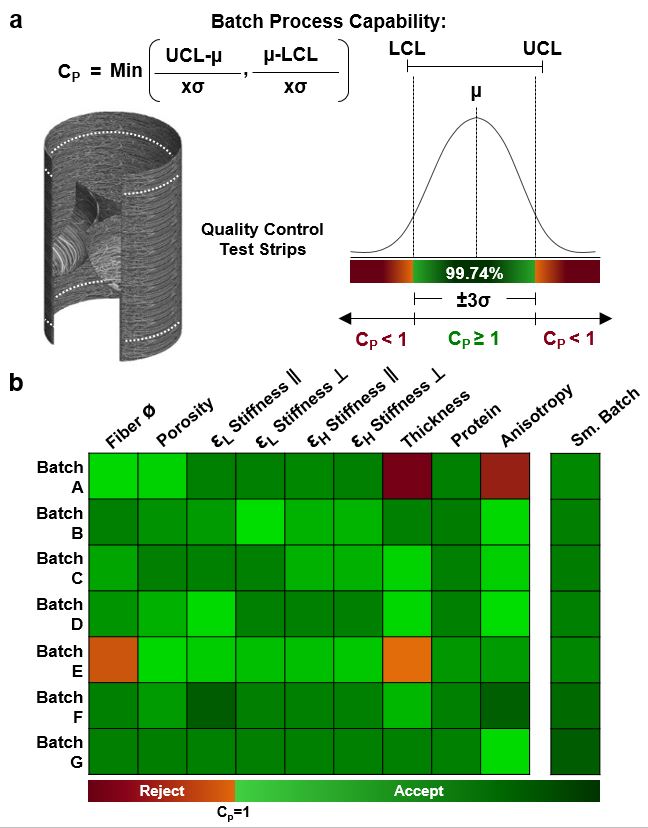
The Batch Process Capability [30] (±3 times the variance) was used to evaluate the manufacturing accuracy and precision of aRJS produced 60/40 P4HB/Gelatin JetValves (N=16 valves, measurements taken from sample strips) for implantation. For fiber diameter, the upper control limit (UCL) was set at 1.2 μm and the lower control limit (LCL) was set at 0.8 μm based upon previously published tissue engineered scaffolds [6, 7, 9]. The porosity UCL was set at 50% and the LCL was set at 30% given the achievable range of the manufacturing process. All JetValve stiffness measurement control limits were based upon the measured stiffnesses of freshly harvested pulmonary leaflets. Low strain stiffness in the circumferential direction control limits ranged from 0–10 MPa and in the radial direction control limits ranged from 0-1 MPa. High strain stiffness in the circumferential and radial directions control limits ranged from 0-20 MPa. For scaffold thickness, sample strip thicknesses ULC was set at 600 μm and the LCL was set at 250 μm. Protein content was taken as the relative amount of P4HB to gelatin in the scaffold as measured by comparing the peak height of the carbonyl stretch peak at 1720 cm−1 (indicative of P4HB) to the amide I peak at 1645 cm−1 (indicative of gelatin) using Fourier Transform Infrared Spectroscopy (FTIR) [25]; the protein content UCL was set at 2.5 and the LCL set at 0.5. The scaffold fiber orientation was measured using the OOP. Based upon OOP of decellularized native leaflet tissue, orientation UCL was set at 0.8 and the LCL was set at 0.375.
2.10 In vitro Functional Testing
Preliminary evaluation of JetValve functionality using an in vitro pulse duplicator system (Vivitro Labs, Pulse Duplicator) was conducted to ensure the integrity of the scaffold leaflet design under physiologic pressures and flows [31]. JetValves of 60/40 P4HB/Gelatin composition were anchored into 30 mm diameter nitinol stents (CARAG; Baar, Switzerland) with 5-0 suture (Ethicon, black monofilament) and continuously loaded for 48 hr under pulmonary-like pressure conditions (N=3 valves). A FDA waveform at 70 beats per minute was applied to the pulse duplicator’s 150 ml silicon ventricle; distal compliance chambers were adjusted to achieve pulmonary-like pressures across the JetValve during diastole with a cardiac output of 2.2 L/min. Valve diameter, beat rate, and cardiac output were within the ranges of previously reported ovine measurements [7, 32]. Ventricular (proximal to the JetValve) and arterial (distal to the JetValve) pressures and intravalvular volumetric flow rates were measured at 48 hr at a sampling rate of 256 samples per cycle.
2.11 In vivo Implantation Deployment and Functional Testing
JetValves of 60/40 composition were implanted into the orthotopic pulmonary valve position of ovine models for deployment and acute functional testing (Fig. 3a). This delivery technique was recently reported to be a viable implantation method for tissue engineered heart valves [7]. The University Hospital Zurich ethics committee (ZH151_2013, Zürich, Switzerland) approved the study in compliance with the Guide for the Care and Use of Laboratory Animals, published by the National Institutes of Health (NIH publication No. 85-23). After a right sided thoracotomy, the pericardium was opened and the right ventricle (RV) was exposed, before it was punctured using needle through purse-string sutures. Next, a guide wire was introduced into the RV and placed into the main pulmonary artery under fluoroscopic control. The scaffold loaded implantation catheter was introduced into the RV over the wire and placed over the native pulmonary valve. Optimal positioning was controlled by contrast angiography, before the scaffold was delivered under fluoroscopic control. After full delivery of the scaffold a final contrast angiography was done to ensure optimal positioning, instant functionality and complete exclusion of the native pulmonary valve (Supplemental videos 2 and 3). The delivery device was removed, the RV was closed with the purse-string, and the thoracotomy was closed. Finally trans-esophageal echocardiographic assessment was performed postoperatively and at 15 hr to evaluate valve functionality. After 15 hr functionality measurements were taken, valves were explanted for visual inspection of structural integrity and H&E staining. The 15 hr evaluation time point was used to test the stability of valve functionality (N=4 implants) after the stresses of minimally invasive delivery on the JetValve/stent construct. Keeping the animal subjects anesthetized for longer periods for this purpose is neither safe for the animal nor was it in the scope of this study.
Fig. 3.

JetValve catheter-based deployment and crimping. (a) Transcatheter delivery involved fixing the scaffold in a self-expanding nitinol stent, transapical placement via entry through the right ventricle (RV), positioning via a guide wire system, deployment of the stented scaffold over the native leaflets, and retraction of the catheter through the ventricle. Radial pressure of the released stent held the valve scaffold in place between the RV and pulmonary artery (PA), over the native valve leaflets. (b) Crimping of anchored JetValves from the 30 mm fully extended conformation to the fully crimped 9mm conformation to accommodate implantation.
For the minimally invasive deployment described above, JetValves were crimped from 30 mm in diameter to 9 mm in diameter and loaded into the implantation catheter. Stress minimization during crimping was a critical design concern because of the non-woven microstructure of the scaffold and resulting potential susceptibility to suture and shear-induced tearing. To test capacity for crimping, JetValves were anchored into nitinol stents via suture and pneumatically crimped from 30 mm (fully extended, adult ovine size) to 9 mm (fully crimped) at 45 psi. Leaflet shape and thickness were optimized to ensure a “swirling” fold during the crimping process that minimized the stresses on the leaflets and leaflet-conduit sutured anchor points (Fig. 3b).
2.12 Statistical Analyses
All statistical analyses were done using SigmaPlot software (v12.0, Systat Software Inc.); the sample size “N” used for statistical analyses are reported in the respective methods Sections 2.3–2.10 above. Analyses of data variance were done using the One-Way ANOVA test (for fiber diameter, porosity, stiffness, and cell infiltration depth) or the Two-Way ANOVA test (for scaffold fiber anisotropy). Pairwise multiple comparison procedures were done using the Tukey Test for fiber diameter, porosity, and cell infiltration data; Dunn’s method for stiffness comparisons; and the Holm-Sidak method for scaffold fiber anisotropy (OOP). For all statistical analyses, p-values less than 0.05 were considered statistically significant and all values reported as mean ± standard error of the mean.
3. Results
3.1 JetValve Biohybrid Structure and Mechanics
Fiber diameter and porosity [33, 34] are structural scaffold parameters that contribute to the degree of endogenous cellular attachment and infiltration during the remodeling process. To control these parameters, we engineered scaffolds composed of biohybrid blends of poly-4-hydroxybutyrate (P4HB) and gelatin (denatured collagen), which is the primary structural component of valve leaflets. By varying the biohybrid concentration within the scaffold, fiber diameter [25] and alignment could be controlled to approximate that of the native valve ECM. We mixed high molecular weight P4HB (MW ~450 kDa) with gelatin (MW ~50–100 kDa) to control solution viscosity and consequently fiber diameter [21, 35]. By decreasing P4HB content, fiber diameter could be reduced (range: 100/0 1.28 ± 0.39 μm to 20/80 680 ± 0.19 nm) to achieve a higher porosity (range: 100/0 41.59 ± 1.58% to 20/80 55.51 ± 2.38%) within the construct (Fig. 1c). Taken together, these data demonstrate that porosity and fiber diameter are inversely related using the JetValve fabrication process.
As in the native valve structural fibrosa, fibers were primarily oriented in the circumferential direction of the scaffold leaflets. This was done to enable the scaffolds to withstand transvalvular loading during diastole; the high Mw of the P4HB and non-woven mesh structure of the fibers allowed for elastic, radial stretching during systole. The continuous deposition of fibers onto mandrels angled 0°, 22.5°, and 45° relative to the fiber extrusion plane produced circumferential alignment within JetValve leaflets, recapitulating the load bearing, collagen-rich fibrosa layer of the native valve ECM [29] (Fig. 4a). However, fiber anisotropy within the conduit portions of the JetValve constructs was significantly reduced although consistent for all angles of collection (Fig. 4a). Because fiber anisotropy varied spatially within JetValves, we asked how collection angle influenced scaffold packing density or porosity in the leaflet versus conduit portions of the constructs. For JetValve leaflets, increasing collection angle decreased scaffold porosity, a trend that was also observed for JetValve conduits (Fig. 4b). For 0° and 22.5° collection angles, leaflet porosities were increased by ~10% compared to conduit porosities of the same angle; however, leaflet and conduit porosities reached similar values when scaffolds were collected at 45°. Taken together, these data support the notion that angle of collection does not affect scaffold anisotropy and that conduits were less anisotropic and porous than leaflets.
Fig. 4.

JetValve leaflet/conduit anisotropy and porosity. (a) JetValve leaflet anisotropy was comparable to native anisotropy, as indicated by OOP, and was significantly more anisotropic than the conduit for each collection angle. Colorized SEM images, right, indicate local fiber direction, (R) indicates radial direction and (C) indicates circumferential direction (N=3 production runs per condition and N=7 native leaflets, *p<0.5 comparing leaflet vs. conduit). (b) Representative SEM images of JetValve leaflet and conduit scaffold collected at 45° (scale bar 500μm). Porosity of leaflets and conduits as a function of collection angles (N=3 production runs per condition, *p<0.5 comparing angles and #p<0.5 comparing leaflet vs conduit for a given angle). Data presented as mean ± s.e.m. (leaflet: grey, conduit: black).
Recapitulating the bulk anisotropy of the native leaflet fibrosa and varying fiber biohybrid composition allowed for control of the bulk biaxial stiffness of JetValves. The mechanical properties of the valvular leaflets determines the stress and strain fields within the tissue during the cardiac cycle, ultimately enabling their functionality [34, 36]. Accordingly, elastic, fibrous scaffolds such as JetValves should be designed to mimic these mechanical properties to ensure optimal functionality in flow [37]. We therefore designed the stretch-dependent, biaxial stiffness of our scaffolds to recapitulate that of the native leaflet ECM. The P4HB/Gelatin ratio of fibers governed the biaxial stiffness of the bulk scaffold at both low and high strains (Fig. 5a). At low strain, in the primary (circumferential) axis of fiber alignment, scaffold stiffness ranged from 505.52 ± 61.72 kPa (40/60) to 5.12 ± 0.82 MPa (100/0) vs. 643.23 ± 215.76 kPa (native); in the perpendicular (radial) axis of fiber alignment, scaffold stiffness ranged from 211.91 ± 31.32 kPa (40/60) to 4.33 ± 0.16 MPa (100/0) vs. 501.41 ± 74.72 kPa (native). At high strain, in the primary (circumferential) axis of fiber alignment, scaffold stiffness ranged from 1.16 ± 0.11 MPa (40/60) to 34.47 ± 1.54 MPa (100/0) vs. 3.33 ± 0.45 MPa (native); in the perpendicular (radial) axis of fiber alignment scaffold stiffness ranged from 338.38 ± 44.31 kPa (40/60) to 13.89 ± 0.75 MPa (100/0) vs. 1.49 ± 0.40 MPa (native). Only when the P4HB/Gelatin ratio of fibers was reduced to 60/40 or 40/60 did scaffold stiffness approximate that of the native leaflet in both strain regimes in the primary and perpendicular axes of fiber alignment.
Fig. 5.

JetValve biaxial stiffness as a function of biohybrid composition, collection angle, and location. (a) Increasing protein percentage within the biohybrid ratio of spun scaffolds decreased the low strain (0–10%) and high strain (10–20%) biaxial global stiffness of scaffolds (N=6 production runs per condition, N=5 native leaflets; *p<0.5, data presented as mean ± s.e.m. (b) Conduit samples comprised of 60/40 P4HB/Gelatin blends were stiffer than corresponding collection angle leaflet samples for both low and high strains (N=6 production runs per conditions; *p<0.5 between leaflet and conduit stiffness for the same collection angle, data presented as mean ± s.e.m.).
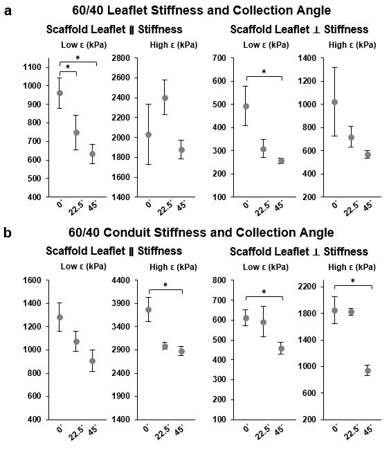
Biohybrid fibers stuck to mandrels at ≥60% gelatin content; we therefore used 60/40 P4HB/Gelatin blends for further functional testing. Because collection angle spatially affected scaffold anisotropy and porosity, we asked if stiffness values were also influenced by collection angle. Biaxial stiffness values generally decreased as a function of increasing collection angle (Fig. 5b and Supplemental Fig. 1). Likely due to increased packing during fiber collection (i.e. reduced porosity), conduit stiffnesses were found to be higher than corresponding collection angle leaflet stiffnesses in both the circumferential and radial directions.
3.2 JetValve Surface Biochemistry and Hydrated Shelf Life
To prepare for stent anchoring and crimping, JetValves were hydrated resulting in more pliable fibers. Because the protein content was not crosslinked, once hydrated the shelf-life of the scaffold would be limited due to passive gelatin diffusion from the surface of the fibers. Using FTIR, initial relative protein content within JetValves was measured by comparing the height of the carbonyl stretch peak (1720 cm−1, indicative of P4HB) with those of the amide I and amide II peaks (1645 and 1535 cm−1 respectively, indicative of gelatin, Fig. 6a) [25]. The 60/40 blend was chosen for functional testing as it most closely mimicked the leaflet structural and mechanical design criteria described above. Additionally, this biohybrid blend maintained a consistent polymer crystallinity over a range of manufacturing spinning speeds (Fig. 6b) in good agreement with previously published studies [6, 7, 9]. The as-spun, dry composition of the 60/40 JetValve blend was measured to be 58.43 ± 2.30% P4HB, 39.85 ± 1.86% gelatin, and 0.44 ± 0.4% HFIP. Once hydrated, the surface gelatin composition of the scaffold increased to 56.42 ± 0.81% but returned to 43.48 ± 0.89% after 7 days in pure water (XPS, Fig. 6c). After this period of hydration, JetValves maintained stiffness similar to as-spun scaffolds (Fig. 6d). Taken together, the shelf life of the hydrated 60/40 JetValves was measured to be at least 1 week.
Fig. 6.

Shelf life composition and stiffness of JetValves. (a) Initial protein content and P4HB crystallinity was measured by comparing carbonyl stretch and amide FTIR absorbency peak heights. (b) Neither protein content nor polymer crystallinity were affected by fiber extrusion spin speed; Biohybrid blends of 60/40 P4HB/Gelatin exhibited stable relative crystallinity for all spin speeds compared to compositions with higher synthetic polymer content (N=3 production runs per condition). (c) Ratiometric (XPS) hydrated scaffold content over the course of 1 week. Inset: trace amounts of bound HFIP solvent were detected upon hydration (N=3 production runs). (d) The biaxial mechanical properties of 1 week hydrated scaffolds compared to those of fresh-spun scaffolds (N=3 production runs per condition; blue represents circumferential (C), red represents radial (R) fiber alignment; data presented as mean ± s.e.m.).
3.3 In Vitro Cellular Infiltration
JetValve composition was designed to mimic previously published, tissue engineered valves that exhibited cellular infiltration and extensive regeneration via endogenous repair mechanisms [6, 7, 9, 33, 38]. Although composed of similar materials to those tissue engineered products previously investigated, we asked if the rapid and non-biological manufacturing of JetValve scaffolds allowed for cellular infiltration and if this integration varied spatially throughout the construct. Primary harvest porcine VICs infiltrated leaflet portions of 60/40 JetValve scaffold in greater abundance than conduit portions of the scaffold by one week in culture (Fig 7a; infiltration depth Leaflet: 14.52 ± 1.16 μm compared to Conduit: 11.09 ± 0.81 μm). However, by two weeks in culture, infiltration depth for leaflet and conduit sections were similar (Leaflet: 27.17 ± 3.56 μm compared to Conduit: 25.68 ± 2.90 μm) although leaflet tissues appeared more densely populated (Fig. 7b).
Fig. 7.

In vitro valvular interstitial cell (VIC) infiltration. (a) VICs infiltrated the JetValve leaflet portion of scaffolds in greater abundance than conduit portions by 1 week; by 2 weeks, infiltration depth evened at ~25–26 μm from the scaffold surface (N=6 production runs/tissues per condition, *p<0.5 between like scaffold areas in time, #p<0.5 between leaflet and conduit at the same time point; data presented as mean ± s.e.m) (b) Representative three dimensional reconstructions of VIC nuclei within the JetValve scaffold (red indicates nuclei of cells on the scaffold surface, while blue indicates the nuclei of cells that have penetrated into the scaffold, all images in isometric 3D view, 40,000 μm2 area).
3.4 aRJS Manufactured JetValve Batch Process Capability
In order to evaluate scaffold quality and fabrication reproducibility, essential for eventual clinical translation [15], we implemented standard industrial manufacturing process controls based upon the JetValve design criteria described above. We accomplished this by analyzing the structural, mechanical, and biochemical batch process capability (CP) of each scaffold fabricated for implantation as a measure of both manufacturing accuracy and precision [30]. Batch Cp specifications were held to standard precision values of ±3 times the batch parameter variance, ensuring that over 99% of scaffolds within a passing batch were within specification. Despite laboratory-scale batch sizes (≤4 valves/batch), manufacturing achieved higher than 70% batch acceptance rate, which was increased to 100% with the addition of small batch correction factors [39] (Supplemental Fig. 2).
3.5 In Vitro and In Vivo JetValve Functional Testing
JetValve functionality was evaluated both in vitro and in vivo. Preliminary evaluation of scaffold function using an in vitro pulse duplicator system was conducted to ensure the integrity of the scaffold leaflets under physiologic pressures and flows. JetValves were continuously loaded for 48 hr under pulmonary-like conditions, maintaining scaffold structural integrity and exhibiting a regurgitant fraction of 30.24 ± 2.07% during diastolic closing (Fig. 8a). In vivo studies were then conducted to determine if 1) JetValve scaffolds could be safely delivered using a minimally invasive method, 2) if the as-spun, acellular scaffolds would be immediately functional upon implantation, and 3) if the scaffold design was biocompatible (i.e. non-thrombogenic). JetValves were delivered transapically into the native pulmonary valve position in an ovine model for 15 hr as a proof-of-concept. Implanted scaffolds revealed acute functionality as sufficient leaflet motion and good coaptation area were observed with non/minor regurgitation fraction on echocardiography. Transvalvular pressure gradients across the valve, <2 mmHg, were also comparable to native leaflets during systole (Fig. 8b, Echo: Supplemental videos 4 and 5; Doppler: Supplemental videos 6 and 7). Gross examination and histological analyses done at the time of explantation revealed competent valves with pliable and intact leaflets. No thrombus formation and initial, what appears to be circulating immune cell infiltration were observed (Supplemental Fig. 3) indicative of the acute safety and compatibility of JetValve scaffolds.
Fig. 8.

In vitro and in vivo functionality. (a) Top: digital photographs from arterial view of mounted JetValves during systole and diastole at 48 hr (dotted lines highlight the JetValve leaflet and conduit edges). Bottom: flow through the JetValve reached ~175 ml/s during peak systole with complete valve closure during diastole (~30% regurgitant fraction, ~10 mmHg transvalvular pressure). (b) Top: distal three-dimensional echocardiography revealed complete leaflet opening and closing during systole and diastole respectively at 15 hr. Bottom: Doppler imaging showed unrestricted blood flow through the JetValve leaflets during systole and complete closure with minor regurgitation fraction during diastole (RV: right ventricle, PA: pulmonary artery).
4. Discussion
In this study, we present a novel method of manufacturing valve replacements containing leaflets with fibrosal-like fiber alignment and global semilunar valve structure in minutes. This level of throughput is a massive improvement in time to manufacture relative to previously reported mandrel-based, fibrous valve fabrication techniques [40, 41]. Slow solution infusion rates (≤2 ml/hr) and grounded-mandrel collection speeds (≤1 RPM) have resulted in production times ranging from 1.5 hr [40] to over 3.5 hr [41] per scaffold using comparable electrospinning methods. By increasing infusion and fiber collection rates by two and three orders of magnitude respectively, we were able to produce 30 mm diameter JetValves in less than fifteen minutes. JetValve production times can be compared to those achievable with 3D printing techniques [42, 43]; however, 3D printing still remains unable to produce the spatial resolution of nano/micro-fiber production platforms. Similarly, hydrogel and soft-polymer molding and patterning techniques for engineering heart valves have been limited to feature resolutions within tens to hundreds of microns [44–47] and often require hours to days for fabrication due to gelation/layer bonding times. In comparison, we were able to achieve fiber resolution ranging from hundreds of nanometers to microns by varying solution composition and collection in order to rapidly recapitulate the size scale and anisotropy of the native fibrosa ECM layer of the valve.
Scaffold biochemical and mechanical properties are critical for guiding tissue regeneration and macro-scale leaflet functionality [48, 49]. Accordingly, the bulk, biaxial stiffness of JetValve leaflets was engineered to match that of native tissue similar to previously reported ‘off-the-shelf’ cell-based manufactured valve scaffolds [7, 9] but without the need for long culture and in vitro conditioning. JetValve stiffness values were an order of magnitude lower than previously reported, as-spun off-the-shelf fibrous scaffolds [50] and commercially available ‘stiff’ bioprosthetic valves (single versus tens of megapascals) [51]. This was made possible by the inclusion of uncrosslinked gelatin in the biohybrid JetValve fibers and varying the collection angle on the aRJS system. Despite not crosslinking JetValves, exposure of biohybrid fibers to water for up to 1 week did not significantly change the stiffness of the scaffold. During this period, P4HB/Gelatin content remained within compositional range for mimicking the measured native tissue stiffness values. This length of hydrated shelf life is comparable to recent fiber/gel valvular scaffold composites [52] and is well in excess of the time required for pre-implantation procedures: on the order of hours for stent fixation, crimping, and surgical delivery preparation.
While recent studies have begun to apply defined standards (e.g. ISO) for the assessment of tissue engineered heart valve functional performance [52, 53], little work has been done to establish industrial-style quality control standards for tissue engineering manufacturing processes and products [54]. Therefore the structural, mechanical, and compositional scaffold design parameters discussed above were measured and evaluated for each JetValve prepared for implantation as a factor of safety for the animal models used. The automated method of JetValve assembly and simplicity of manufacturing customization enabled straightforward implementation of multi-parameter process capability metrics [55, 56]. Our group has developed similar multi-parameter quality assessment indices for stem cell manufacturing [27, 57] and suggest that the same can and should be done for tissue engineered products [19]. We envision batch process capability and other quality control metrics may likewise be applied to future JetValve designs and similar automated in situ tissue engineered scaffold processes to ensure patient or model safety prior to functional testing.
Restoration of valvular functionality upon implantation is the immediate goal of regenerative scaffolds. As-manufactured JetValves showed potential as functioning and biocompatible valves both in vitro and in vivo after crimping and minimally invasive delivery. Scaffold stiffness plays a critical role in leaflet kinematics and the development of transvalvular pressure gradients during systole [58, 59]. As in previously proposed polymer/gelatin composite models for achieving native tissue-like stiffnesses [60], the biohybrid JetValve scaffold composition was tuned to mimic native ECM leaflet stiffness. As a result, transvalvular pressure gradients of <2 mmHg were observed in vivo which is equivalent to recently published human and ovine tissue engineered heart valve (<5 mmHg) [31, 53]. However, in vitro pulse duplicator testing did reveal a regurgitant fraction of approximately 30% which is above ISO standards of similarly sized heart valves [52]. These data did not appear, though, to fully predict JetValve functionality in vivo where rapid and complete leaflet coaptation and minimal closing jet were observed with echo/doppler imaging. JetValves were mounted in the pulse duplicator system in the absence of radial loading which is normally applied in vivo by the surrounding tissue (pulmonary artery and valve annulus). This resulted in full expansion of the stent and may explain the level of measured regurgitation in vitro. While these data do not necessarily give indication as to the regenerative capacity or long-term functionality of JetValves, they do support the manufacturing method as viable. These time points, 48 hr in vitro and 15 hr in vivo, indicate that the JetValve manufacturing technique can be used to produce a working, semilunar valve structure amenable to minimally invasive implantation with acute safety. Future iterations of the JetValve scaffold will reveal which compositions and spinning/collection parameters will be necessary for long-term functionality and tissue regeneration.
In addition to restoring function, the long-term goal of all regenerative, in situ tissue engineered scaffolds is to promote both full regeneration and adaptive growth of the target tissue. Such scaffolds should serve as resorbable platforms onto and into which the body can “auto-engineer” its own replacement tissue that, ideally, perfectly matches healthy native tissue. This requires intricate engineering design of scaffold architectural, mechanical, and biochemical properties [50] to control time-dependent biological processes including cellular recruitment, inflammation, and scaffold remodeling [61]. Here, we showed that 60/40, as-spun JetValves supported progressive VIC infiltration and tissue growth at least in vitro, suggestive of their potential for serving as scaffolds for long-term endogenous tissue formation in vivo. However, these studies are limited in length and cell demographics; it is likely that that inclusion of anti-inflammatory agents and/or growth factors may be necessary for endogenous repair mechanism to be activated. Inclusion of these factors as dopants is possible using the JetValve manufacturing method without significant modification to the technique or time to production. Growth factors associated with development such as transforming growth factor-β1 (TGF-β1), bone morphogenic proteins (BMPs), and/or platelet-derived growth factors (PDGFs) may be incorporated into scaffolds to elicit endothelial-to-mesenchymal transformation (EMT), for example, in order to populate and remodel the scaffold [55, 62, 63]. Additionally, recently reported hybrid-manufacturing techniques for the production of more complex, tri-layered scaffolds have been developed in an effort to better mimic the anisotropic, stratified structure of the valvular ECM for optimal hemodynamic performance and tissue regeneration [52, 64–66]. The JetValve production platform is amenable to fabrication of similarly layered scaffolds while maintaining industrial-like scaffold production rates [67–69] due to its additive nature. By successively spinning fibrosa, spongiosa, and ventricularis-like layers of biohybrid materials with mechanical properties and biochemistry tailored to the specific ECM layers of the valve, stratified JetValve production could be possible.
We further propose that this method can be valuable for the fabrication or other fibrous replacement organ scaffolds or for production of customized scaffolds given the specific age, size, and organ or organ-part needs of a patient [19]. Fibrous, vascularized tissue such as myocardium or branching blood vessels may incorporate vascular endothelial growth factors (VEGFs), angiopoietins, or ephrins to elicit neovascularization within the scaffold [70]. Although precise growth factor combinations and amounts needed to recruit tissue specific cell progenitors remains to be identified [15, 71], the flexibility of the JetValve manufacturing process described here would allow for easy incorporation of multiple factors into scaffolds to promote homing and assembly of endogenous cells and tissues. Furthermore, because mandrels can be 3D printed in any shape, scaffolds of customized anatomy may be spun using this technique: combining the JetValve mandrel-based spinning process with the idea of 3D printing patient specific organ geometries [43, 72–74]. The manufacturing process we report here is well suited to rapidly and iteratively study the properties and compositions needed for fibrous scaffold-based endogenous tissue repair and is amenable to patient-specific customization.
5. Conclusion
In this study, we have introduced a manufacturing process for the rapid fabrication of fibrous, semilunar heart valve scaffolds. By varying manufacturing parameters such as solution composition, extrusion speed, and mandrel size or collection angle, functional scaffolds were built to model basic native valvular ECM. This method is amenable to further customization by tuning the same multiscale structural, mechanical, and biochemical scaffold parameters to potentially match the anatomy of specific patients and/or determine which values of these parameters will elicit an ideal remodeling response once implanted. Because scaffolds were fabricated three-dimensionally, they could easily be incorporated into stents and implanted minimally invasively as-spun, without the need for post processing or in vitro preconditioning. The simplicity and control of this scaffold manufacturing process offers a viable, cell-free and potentially clinically translatable alternative for the fabrication of heart valves and possibly other fibrous organs.
Supplementary Material
JetValve leaflet and conduit scaffold stiffness as a function of collection and angle. (a) At low strains, both in the parallel (circumferential) and perpendicular (radial) directions of fiber alignment, leaflet stiffness in JetValves comprised of 60/40 P4HB/Gelatin decreased as a function of increasing collection angle. A similar trend was measured in the perpendicular direction at high strain but was not statistically significant. (b) At both low and high strains, conduit stiffness decreased as a function of increasing collection angle, the trend was present but not statistically significant at low strains in the parallel direction. For all data comparisons *p<0.5, data presented as mean ± s.e.m.
Batch Process Capability Quality Control. (a) Batch process capability (CP) was calculated for each batch of JetValves by taking sample strips fabricated using the JetValve scaffold manufacturing process (dashed lines). Acceptable manufacturing Upper Control Limits (UCL) and Lower Control Limits (LCL) were set for each capability criteria (see Materials and Methods); CP is the minimal ratio of the distance from the mean (μ) of a design criteria value to each control limit and the allowable variance (σ), taken as 3 standard deviations away from the mean in industrial manufacturing. A CP of 1 or greater is taken as acceptable (green shading) while a CP less than 1 (red shading) in any tested design criteria results in batch rejection due to high variance (i.e. manufacturing inconsistency). (b) Example CP report of N=7 production runs. Applying industrial CP standards, the JetValve manufacturing process achieved a 70% batch acceptance rate, whereas applying a small batch correction factor resulted in 100% batch acceptance.
Histological examination of explanted JetValves at 15 hr post-implantation. JetValves explanted 15 hr after implantation revealed no/minor thrombus formation on the intact leaflets. Hematoxylin and eosin (H&E) staining of explanted JetValves showed limited scaffold infiltration of circulating immune cells (scale bars: 10 mm pulmonary view, 20 mm cross sectional view, 2 mm cross sectional histology, and 100 μm histology inset; histology: pink is gelatin and blue/purple are cell nuclei).
Acknowledgments
We thank the Wyss Institute of Biologically Inspired Engineering at Harvard University for their ongoing support throughout this project. We also thank Harvard Center for Nanoscale Systems (CNS) for the use of imaging facilities in the characterization of valvular scaffolds and tissues; the CNS is a member of the National Nanotechnology Infrastructure Network (NNIN), which is supported by the National Science Foundation under NSF award no. 1541959. This work was partially funded by the Defense Threat Reduction Agency (DTRA) by subcontract #312659 from Los Alamos National Laboratory under a prime DTRA contract no. DE-AC52-06NA25396 and the National Institutes of Health award no. UH3TR000522. We thank John Ferrier and Matthew Griswold for their assistance in the building of the automated Rotary Jet spinning System and James Weaver for 3D printing valve mandrels of various sizes.
Footnotes
Author Contributions
A.K.C. was the lead author on the manuscript with significant editorial contribution from M.Y.E., J.U.L, F.S.P., S.P.H., and K.K.P. K.K.P., S.P.H., and A.K.C conceived the project. A.K.C. designed and built the JetValve spinning process with design input from M.Y.E., D.K, and B.W. A.K.C., S.J.P, and J.A.G. designed and built the automated Rotary Jet Spinning system. A.K.C., D.K., F.S.P., S. A., and J.U.L. performed structural, mechanical, and biochemical analyses of JetValve scaffolds and A.K.C and S.P.S implemented batch process capability measurements based on these data. D.K. prepared and coordinated JetValve scaffolds for implantation/explantation and M.Y.E. and E.C. performed the surgical delivery and removal of JetValves.
Competing Financial Interests
The authors declare no competing financial interests.
Publisher's Disclaimer: This is a PDF file of an unedited manuscript that has been accepted for publication. As a service to our customers we are providing this early version of the manuscript. The manuscript will undergo copyediting, typesetting, and review of the resulting proof before it is published in its final citable form. Please note that during the production process errors may be discovered which could affect the content, and all legal disclaimers that apply to the journal pertain.
References
- 1.Chaikof EL. The development of prosthetic heart valves—lessons in form and function. New England Journal of Medicine. 2007;357(14):1368–1371. doi: 10.1056/NEJMp078175. [DOI] [PubMed] [Google Scholar]
- 2.Jana S, Tranquillo RT, Lerman A. Cells for tissue engineering of cardiac valves. Journal of tissue engineering and regenerative medicine. 2015 doi: 10.1002/term.2010. [DOI] [PubMed] [Google Scholar]
- 3.Robinson PS, Johnson SL, Evans MC, Barocas VH, Tranquillo RT. Functional tissue-engineered valves from cell-remodeled fibrin with commissural alignment of cell-produced collagen. Tissue Engineering Part A. 2008;14(1):83–95. doi: 10.1089/ten.a.2007.0148. [DOI] [PubMed] [Google Scholar]
- 4.Jana S, Tefft B, Spoon D, Simari RD. Scaffolds for tissue engineering of cardiac valves. Acta biomaterialia. 2014;10(7):2877–2893. doi: 10.1016/j.actbio.2014.03.014. [DOI] [PubMed] [Google Scholar]
- 5.Badylak SF. A scaffold immune microenvironment. Science. 2016;352(6283):298–298. doi: 10.1126/science.aaf7587. [DOI] [PubMed] [Google Scholar]
- 6.Weber B, Dijkman PE, Scherman J, Sanders B, Emmert MY, Grünenfelder J, Verbeek R, Bracher M, Black M, Franz T. Off-the-shelf human decellularized tissue-engineered heart valves in a non-human primate model. Biomaterials. 2013;34(30):7269–7280. doi: 10.1016/j.biomaterials.2013.04.059. [DOI] [PubMed] [Google Scholar]
- 7.Driessen-Mol A, Emmert MY, Dijkman PE, Frese L, Sanders B, Weber B, Cesarovic N, Sidler M, Leenders J, Jenni R. Transcatheter implantation of homologous “off-the-shelf” tissue-engineered heart valves with self-repair capacity: long-term functionality and rapid in vivo remodeling in sheep. Journal of the American College of Cardiology. 2014;63(13):1320–1329. doi: 10.1016/j.jacc.2013.09.082. [DOI] [PubMed] [Google Scholar]
- 8.Syedain ZH, Bradee AR, Kren S, Taylor DA, Tranquillo RT. Decellularized tissue-engineered heart valve leaflets with recellularization potential. Tissue Engineering Part A. 2012;19(5–6):759–769. doi: 10.1089/ten.tea.2012.0365. [DOI] [PMC free article] [PubMed] [Google Scholar]
- 9.Dijkman PE, Driessen-Mol A, Frese L, Hoerstrup SP, Baaijens FP. Decellularized homologous tissue-engineered heart valves as off-the-shelf alternatives to xeno-and homografts. Biomaterials. 2012;33(18):4545–4554. doi: 10.1016/j.biomaterials.2012.03.015. [DOI] [PubMed] [Google Scholar]
- 10.Sengupta D, Waldman SD, Li S. From in vitro to in situ tissue engineering. Annals of biomedical engineering. 2014;42(7):1537–1545. doi: 10.1007/s10439-014-1022-8. [DOI] [PubMed] [Google Scholar]
- 11.Schaefermeier PK, Cabeza N, Besser JC, Lohse P, Daebritz SH, Schmitz C, Reichart B, Sodian R. Potential cell sources for tissue engineering of heart valves in comparison with human pulmonary valve cells. ASAIO Journal. 2009;55(1):86–92. doi: 10.1097/MAT.0b013e31818f54e4. [DOI] [PubMed] [Google Scholar]
- 12.Emmert MY, Hoerstrup SP. Tissue engineered heart valves: moving towards clinical translation. Expert Review of Medical Devices (just-accepted) 2016 doi: 10.1586/17434440.2016.1171709. [DOI] [PubMed] [Google Scholar]
- 13.Archer R, Williams DJ. Why tissue engineering needs process engineering. Nature biotechnology. 2005;23(11):1353–1355. doi: 10.1038/nbt1105-1353. [DOI] [PubMed] [Google Scholar]
- 14.Christians U, Klawitter J, Klawitter J, Brunner N, Schmitz V. Biomarkers of immunosuppressant organ toxicity after transplantation: status, concepts and misconceptions. Expert opinion on drug metabolism & toxicology. 2011;7(2):175–200. doi: 10.1517/17425255.2011.544249. [DOI] [PMC free article] [PubMed] [Google Scholar]
- 15.Schoen FJ. Heart valve tissue engineering: quo vadis? Current Opinion in Biotechnology. 2011;22(5):698–705. doi: 10.1016/j.copbio.2011.01.004. [DOI] [PubMed] [Google Scholar]
- 16.Webber MJ, Khan OF, Sydlik SA, Tang BC, Langer R. A perspective on the clinical translation of scaffolds for tissue engineering. Annals of biomedical engineering. 2015;43(3):641–656. doi: 10.1007/s10439-014-1104-7. [DOI] [PMC free article] [PubMed] [Google Scholar]
- 17.Place ES, Evans ND, Stevens MM. Complexity in biomaterials for tissue engineering. Nature materials. 2009;8(6):457–470. doi: 10.1038/nmat2441. [DOI] [PubMed] [Google Scholar]
- 18.Dijkman P, Fioretta E, Frese L, Pasqualini F, Hoerstrup S. Heart valve replacements with regenerative capacity. Transfusion Medicine and Hemotherapy. 2016;43(4):282–290. doi: 10.1159/000448181. [DOI] [PMC free article] [PubMed] [Google Scholar]
- 19.Capulli A, MacQueen L, Sheehy SP, Parker K. Fibrous scaffolds for building hearts and heart parts. Advanced drug delivery reviews. 2016;96:83–102. doi: 10.1016/j.addr.2015.11.020. [DOI] [PMC free article] [PubMed] [Google Scholar]
- 20.Szentivanyi A, Chakradeo T, Zernetsch H, Glasmacher B. Electrospun cellular microenvironments: understanding controlled release and scaffold structure. Advanced drug delivery reviews. 2011;63(4):209–220. doi: 10.1016/j.addr.2010.12.002. [DOI] [PubMed] [Google Scholar]
- 21.Badrossamay MR, McIlwee HA, Goss JA, Parker KK. Nanofiber assembly by rotary jet-spinning. Nano letters. 2010;10(6):2257–2261. doi: 10.1021/nl101355x. [DOI] [PMC free article] [PubMed] [Google Scholar]
- 22.Zhang X, Xu B, Puperi DS, Wu Y, West JL, Grande-Allen KJ. Application of hydrogels in heart valve tissue engineering. Journal of long-term effects of medical implants. 2015;25:1–2. doi: 10.1615/jlongtermeffmedimplants.2015011817. [DOI] [PMC free article] [PubMed] [Google Scholar]
- 23.Jana S, Lerman A. Bioprinting a cardiac valve. Biotechnology advances. 2015;33(8):1503–1521. doi: 10.1016/j.biotechadv.2015.07.006. [DOI] [PubMed] [Google Scholar]
- 24.Cheung DY, Duan B, Butcher JT. Current progress in tissue engineering of heart valves: multiscale problems, multiscale solutions. Expert opinion on biological therapy. 2015;15(8):1155–1172. doi: 10.1517/14712598.2015.1051527. [DOI] [PMC free article] [PubMed] [Google Scholar]
- 25.Badrossamay MR, Balachandran K, Capulli AK, Golecki HM, Agarwal A, Goss JA, Kim H, Shin K, Parker KK. Engineering hybrid polymer-protein super-aligned nanofibers via rotary jet spinning. Biomaterials. 2014;35(10):3188–3197. doi: 10.1016/j.biomaterials.2013.12.072. [DOI] [PubMed] [Google Scholar]
- 26.Barbour K, SHuang H-Y, Huang HS. The Stress Relaxation Behaviors of Diseased Heart Valve Tissues [Google Scholar]
- 27.Pasqualini FS, Sheehy SP, Agarwal A, Aratyn-Schaus Y, Parker KK. Structural phenotyping of stem cell-derived cardiomyocytes. Stem cell reports. 2015;4(3):340–347. doi: 10.1016/j.stemcr.2015.01.020. [DOI] [PMC free article] [PubMed] [Google Scholar]
- 28.Rezakhaniha R, Agianniotis A, Schrauwen JTC, Griffa A, Sage D, Bouten C, Van de Vosse F, Unser M, Stergiopulos N. Experimental investigation of collagen waviness and orientation in the arterial adventitia using confocal laser scanning microscopy. Biomechanics and modeling in mechanobiology. 2012;11(3–4):461–473. doi: 10.1007/s10237-011-0325-z. [DOI] [PubMed] [Google Scholar]
- 29.Capulli AK, MacQueen LA, O’Connor BB, Dauth S, Parker KK. Acute pergolide exposure stiffens engineered valve interstitial cell tissues and reduces contractility in vitro. Cardiovascular Pathology. 2016;25(4):316–324. doi: 10.1016/j.carpath.2016.04.004. [DOI] [PMC free article] [PubMed] [Google Scholar]
- 30.Lipták BG. Process Control: Instrument Engineers’ Handbook. Butterworth-Heinemann; 2013. [Google Scholar]
- 31.Reimer JM, Syedain ZH, Haynie BH, Tranquillo RT. Pediatric tubular pulmonary heart valve from decellularized engineered tissue tubes. Biomaterials. 2015;62:88–94. doi: 10.1016/j.biomaterials.2015.05.009. [DOI] [PMC free article] [PubMed] [Google Scholar]
- 32.Yelderman M, Quinn M, McKown R, Eberhart R, Dollar M. Continuous thermodilution cardiac output measurement in sheep. The Journal of thoracic and cardiovascular surgery. 1992;104(2):315–320. [PubMed] [Google Scholar]
- 33.Balguid A, Mol A, van Marion MH, Bank RA, Bouten CV, Baaijens FP. Tailoring fiber diameter in electrospun poly (3-caprolactone) scaffolds for optimal cellular infiltration in cardiovascular tissue engineering. Tissue Engineering Part A. 2008;15(2):437–444. doi: 10.1089/ten.tea.2007.0294. [DOI] [PubMed] [Google Scholar]
- 34.Sacks MS, Schoen FJ, Mayer JE., Jr Bioengineering challenges for heart valve tissue engineering. Annual review of biomedical engineering. 2009;11:289–313. doi: 10.1146/annurev-bioeng-061008-124903. [DOI] [PubMed] [Google Scholar]
- 35.Mellado P, McIlwee HA, Badrossamay MR, Goss JA, Mahadevan L, Parker KK. A simple model for nanofiber formation by rotary jet-spinning. Applied Physics Letters. 2011;99(20):203107. [Google Scholar]
- 36.Aggarwal A, Sacks MS. A framework for determination of heart valves’ mechanical properties using inverse-modeling approach. International Conference on Functional Imaging and Modeling of the Heart; Springer; 2015. pp. 285–294. [Google Scholar]
- 37.Hobson CM, Amoroso NJ, Amini R, Ungchusri E, Hong Y, D’Amore A, Sacks MS, Wagner WR. Fabrication of elastomeric scaffolds with curvilinear fibrous structures for heart valve leaflet engineering. Journal of Biomedical Materials Research Part A. 2015;103(9):3101–3106. doi: 10.1002/jbm.a.35450. [DOI] [PMC free article] [PubMed] [Google Scholar]
- 38.Hoerstrup SP, Sodian R, Daebritz S, Wang J, Bacha EA, Martin DP, Moran AM, Guleserian KJ, Sperling JS, Kaushal S. Functional living trileaflet heart valves grown in vitro. Circulation. 2000;102(suppl 3):Iii-44–Iii-49. doi: 10.1161/01.cir.102.suppl_3.iii-44. [DOI] [PubMed] [Google Scholar]
- 39.Yu T, Wang G. The process quality control of single-piece and small-batch products in advanced manufacturing environment, Industrial Engineering and Engineering Management, 2009. IE&EM'09. 16th International Conference on, IEEE; 2009; pp. 306–310. [Google Scholar]
- 40.Del Gaudio C, Bianco A, Grigioni M. Electrospun bioresorbable trileaflet heart valve prosthesis for tissue engineering: in vitro functional assessment of a pulmonary cardiac valve design. Annali dell’Istituto superiore di sanita. 2007;44(2):178–186. [PubMed] [Google Scholar]
- 41.Van Lieshout M, Vaz C, Rutten M, Peters G, Baaijens F. Electrospinning versus knitting: two scaffolds for tissue engineering of the aortic valve, Journal of Biomaterials Science. Polymer Edition. 2006;17(1–2):77–89. doi: 10.1163/156856206774879153. [DOI] [PubMed] [Google Scholar]
- 42.Lueders C, Jastram B, Hetzer R, Schwandt H. Rapid manufacturing techniques for the tissue engineering of human heart valves. European Journal of Cardio-Thoracic Surgery. 2014:ezt510. doi: 10.1093/ejcts/ezt510. [DOI] [PubMed] [Google Scholar]
- 43.Hockaday L, Kang K, Colangelo N, Cheung P, Duan B, Malone E, Wu J, Girardi L, Bonassar L, Lipson H. Rapid 3D printing of anatomically accurate and mechanically heterogeneous aortic valve hydrogel scaffolds. Biofabrication. 2012;4(3):035005. doi: 10.1088/1758-5082/4/3/035005. [DOI] [PMC free article] [PubMed] [Google Scholar]
- 44.Chen Q, Bruyneel A, Clarke K, Carr C, Czernuszka J. Collagen-based scaffolds for potential application of heart valve tissue engineering. Journal of Tissue Science & Engineering 2013. 2013 [Google Scholar]
- 45.Masoumi N, Johnson KL, Howell MC, Engelmayr GC. Valvular interstitial cell seeded poly (glycerol sebacate) scaffolds: toward a biomimetic in vitro model for heart valve tissue engineering. Acta biomaterialia. 2013;9(4):5974–5988. doi: 10.1016/j.actbio.2013.01.001. [DOI] [PubMed] [Google Scholar]
- 46.Kolewe ME, Park H, Gray C, Ye X, Langer R, Freed LE. 3D structural patterns in scalable, elastomeric scaffolds guide engineered tissue architecture. Advanced Materials. 2013;25(32):4459–4465. doi: 10.1002/adma.201301016. [DOI] [PMC free article] [PubMed] [Google Scholar]
- 47.Zhang X, Xu B, Puperi DS, Yonezawa AL, Wu Y, Tseng H, Cuchiara ML, West JL, Grande-Allen KJ. Integrating valve-inspired design features into poly (ethylene glycol) hydrogel scaffolds for heart valve tissue engineering. Acta biomaterialia. 2015;14:11–21. doi: 10.1016/j.actbio.2014.11.042. [DOI] [PMC free article] [PubMed] [Google Scholar]
- 48.Bouten C, Dankers P, Driessen-Mol A, Pedron S, Brizard A, Baaijens F. Substrates for cardiovascular tissue engineering. Advanced drug delivery reviews. 2011;63(4):221–241. doi: 10.1016/j.addr.2011.01.007. [DOI] [PubMed] [Google Scholar]
- 49.Liu W, Thomopoulos S, Xia Y. Electrospun nanofibers for regenerative medicine. Advanced healthcare materials. 2012;1(1):10–25. doi: 10.1002/adhm.201100021. [DOI] [PMC free article] [PubMed] [Google Scholar]
- 50.Hinderer S, Seifert J, Votteler M, Shen N, Rheinlaender J, Schäffer TE, Schenke-Layland K. Engineering of a bio-functionalized hybrid off-the-shelf heart valve. Biomaterials. 2014;35(7):2130–2139. doi: 10.1016/j.biomaterials.2013.10.080. [DOI] [PubMed] [Google Scholar]
- 51.Kalejs M, Stradins P, Lacis R, Ozolanta I, Pavars J, Kasyanov V. St Jude Epic heart valve bioprostheses versus native human and porcine aortic valves–comparison of mechanical properties. Interactive cardiovascular and thoracic surgery. 2009;8(5):553–556. doi: 10.1510/icvts.2008.196220. [DOI] [PubMed] [Google Scholar]
- 52.Moreira R, Neusser C, Kruse M, Mulderrig S, Wolf F, Spillner J, Schmitz-Rode T, Jockenhoevel S, Mela P. Tissue-Engineered Fibrin-Based Heart Valve with Bio-Inspired Textile Reinforcement. Advanced Healthcare Materials. 2016 doi: 10.1002/adhm.201600300. [DOI] [PubMed] [Google Scholar]
- 53.Syedain Z, Reimer J, Schmidt J, Lahti M, Berry J, Bianco R, Tranquillo RT. 6-Month aortic valve implantation of an off-the-shelf tissue-engineered valve in sheep. Biomaterials. 2015;73:175–184. doi: 10.1016/j.biomaterials.2015.09.016. [DOI] [PMC free article] [PubMed] [Google Scholar]
- 54.Melchels FP, Domingos MA, Klein TJ, Malda J, Bartolo PJ, Hutmacher DW. Additive manufacturing of tissues and organs. Progress in Polymer Science. 2012;37(8):1079–1104. [Google Scholar]
- 55.Hasan A, Saliba J, Modarres HP, Bakhaty A, Nasajpour A, Mofrad MR, Sanati-Nezhad A. Micro and nanotechnologies in heart valve tissue engineering. Biomaterials. 2016;103:278–292. doi: 10.1016/j.biomaterials.2016.07.001. [DOI] [PubMed] [Google Scholar]
- 56.Sanz-Garcia A, Oliver-De-La-Cruz J, Mirabet V, Gandía C, Villagrasa A, Sodupe E, Escobedo-Lucea C. Heart valve tissue engineering: how far is the bedside from the bench? Expert reviews in molecular medicine. 2015;17:e16. doi: 10.1017/erm.2015.15. [DOI] [PubMed] [Google Scholar]
- 57.Sheehy SP, Pasqualini F, Grosberg A, Park SJ, Aratyn-Schaus Y, Parker KK. Quality metrics for stem cell-derived cardiac myocytes. Stem cell reports. 2014;2(3):282–294. doi: 10.1016/j.stemcr.2014.01.015. [DOI] [PMC free article] [PubMed] [Google Scholar]
- 58.Duan B, Kapetanovic E, Hockaday LA, Butcher JT. Three-dimensional printed trileaflet valve conduits using biological hydrogels and human valve interstitial cells. Acta biomaterialia. 2014;10(5):1836–1846. doi: 10.1016/j.actbio.2013.12.005. [DOI] [PMC free article] [PubMed] [Google Scholar]
- 59.Merryman WD, Youn I, Lukoff HD, Krueger PM, Guilak F, Hopkins RA, Sacks MS. Correlation between heart valve interstitial cell stiffness and transvalvular pressure: implications for collagen biosynthesis. American Journal of Physiology-Heart and Circulatory Physiology. 2006;290(1):H224–H231. doi: 10.1152/ajpheart.00521.2005. [DOI] [PubMed] [Google Scholar]
- 60.Stradins P, Kalejs M, Lacis R, Ozolanta I, Murovska M, Kasyanov V. Polymer Nanofiber Materials Matching Mechanical Properties of Native Aortic Valve. Medical Basic Sciences. 2013 [Google Scholar]
- 61.Bouten CV, Driessen-Mol A, Baaijens FP. In situ heart valve tissue engineering: simple devices, smart materials, complex knowledge. Expert review of medical devices. 2012;9(5):453–455. doi: 10.1586/erd.12.43. [DOI] [PubMed] [Google Scholar]
- 62.Schroeder JA, Jackson LF, Lee DC, Camenisch TD. Form and function of developing heart valves: coordination by extracellular matrix and growth factor signaling. Journal of molecular medicine. 2003;81(7):392–403. doi: 10.1007/s00109-003-0456-5. [DOI] [PubMed] [Google Scholar]
- 63.Sewell-Loftin M, Chun YW, Khademhosseini A, Merryman WD. EMT-inducing biomaterials for heart valve engineering: taking cues from developmental biology. Journal of cardiovascular translational research. 2011;4(5):658–671. doi: 10.1007/s12265-011-9300-4. [DOI] [PMC free article] [PubMed] [Google Scholar]
- 64.Masoumi N, Annabi N, Assmann A, Larson BL, Hjortnaes J, Alemdar N, Kharaziha M, Manning KB, Mayer JE, Khademhosseini A. Tri-layered elastomeric scaffolds for engineering heart valve leaflets. Biomaterials. 2014;35(27):7774–7785. doi: 10.1016/j.biomaterials.2014.04.039. [DOI] [PMC free article] [PubMed] [Google Scholar]
- 65.Eslami M, Vrana NE, Zorlutuna P, Sant S, Jung S, Masoumi N, Khavari-Nejad RA, Javadi G, Khademhosseini A. Fiber-reinforced hydrogel scaffolds for heart valve tissue engineering. Journal of biomaterials applications. 2014 doi: 10.1177/0885328214530589. 0885328214530589. [DOI] [PubMed] [Google Scholar]
- 66.Puperi DS, Kishan A, Punske ZE, Wu Y, Cosgriff-Hernandez E, West JL, Grande-Allen KJ. Electrospun Polyurethane and Hydrogel Composite Scaffolds as Biomechanical Mimics for Aortic Valve Tissue Engineering. ACS Biomaterials Science & Engineering. 2016 doi: 10.1021/acsbiomaterials.6b00309. [DOI] [PMC free article] [PubMed] [Google Scholar]
- 67.Tamayol A, Akbari M, Annabi N, Paul A, Khademhosseini A, Juncker D. Fiber-based tissue engineering: progress, challenges, and opportunities. Biotechnology advances. 2013;31(5):669–687. doi: 10.1016/j.biotechadv.2012.11.007. [DOI] [PMC free article] [PubMed] [Google Scholar]
- 68.Peltola SM, Melchels FP, Grijpma DW, Kellomäki M. A review of rapid prototyping techniques for tissue engineering purposes. Annals of medicine. 2008;40(4):268–280. doi: 10.1080/07853890701881788. [DOI] [PubMed] [Google Scholar]
- 69.Yeong WY, Chua CK, Leong KF, Chandrasekaran M. Rapid prototyping in tissue engineering: challenges and potential. Trends in biotechnology. 2004;22(12):643–652. doi: 10.1016/j.tibtech.2004.10.004. [DOI] [PubMed] [Google Scholar]
- 70.Yancopoulos GD, Davis S, Gale NW, Rudge JS, Wiegand SJ, Holash J. Vascular-specific growth factors and blood vessel formation. Nature. 2000;407(6801):242–248. doi: 10.1038/35025215. [DOI] [PubMed] [Google Scholar]
- 71.Mendelson K, Schoen FJ. Heart valve tissue engineering: concepts, approaches, progress, and challenges. Annals of biomedical engineering. 2006;34(12):1799–1819. doi: 10.1007/s10439-006-9163-z. [DOI] [PMC free article] [PubMed] [Google Scholar]
- 72.Rengier F, Mehndiratta A, von Tengg-Kobligk H, Zechmann CM, Unterhinninghofen R, Kauczor HU, Giesel FL. 3D printing based on imaging data: review of medical applications. International journal of computer assisted radiology and surgery. 2010;5(4):335–341. doi: 10.1007/s11548-010-0476-x. [DOI] [PubMed] [Google Scholar]
- 73.Lee JY, Choi B, Wu B, Lee M. Customized biomimetic scaffolds created by indirect three-dimensional printing for tissue engineering. Biofabrication. 2013;5(4):045003. doi: 10.1088/1758-5082/5/4/045003. [DOI] [PMC free article] [PubMed] [Google Scholar]
- 74.Murphy SV, Atala A. 3D bioprinting of tissues and organs. Nature biotechnology. 2014;32(8):773–785. doi: 10.1038/nbt.2958. [DOI] [PubMed] [Google Scholar]
Associated Data
This section collects any data citations, data availability statements, or supplementary materials included in this article.
Supplementary Materials
JetValve leaflet and conduit scaffold stiffness as a function of collection and angle. (a) At low strains, both in the parallel (circumferential) and perpendicular (radial) directions of fiber alignment, leaflet stiffness in JetValves comprised of 60/40 P4HB/Gelatin decreased as a function of increasing collection angle. A similar trend was measured in the perpendicular direction at high strain but was not statistically significant. (b) At both low and high strains, conduit stiffness decreased as a function of increasing collection angle, the trend was present but not statistically significant at low strains in the parallel direction. For all data comparisons *p<0.5, data presented as mean ± s.e.m.
Batch Process Capability Quality Control. (a) Batch process capability (CP) was calculated for each batch of JetValves by taking sample strips fabricated using the JetValve scaffold manufacturing process (dashed lines). Acceptable manufacturing Upper Control Limits (UCL) and Lower Control Limits (LCL) were set for each capability criteria (see Materials and Methods); CP is the minimal ratio of the distance from the mean (μ) of a design criteria value to each control limit and the allowable variance (σ), taken as 3 standard deviations away from the mean in industrial manufacturing. A CP of 1 or greater is taken as acceptable (green shading) while a CP less than 1 (red shading) in any tested design criteria results in batch rejection due to high variance (i.e. manufacturing inconsistency). (b) Example CP report of N=7 production runs. Applying industrial CP standards, the JetValve manufacturing process achieved a 70% batch acceptance rate, whereas applying a small batch correction factor resulted in 100% batch acceptance.
Histological examination of explanted JetValves at 15 hr post-implantation. JetValves explanted 15 hr after implantation revealed no/minor thrombus formation on the intact leaflets. Hematoxylin and eosin (H&E) staining of explanted JetValves showed limited scaffold infiltration of circulating immune cells (scale bars: 10 mm pulmonary view, 20 mm cross sectional view, 2 mm cross sectional histology, and 100 μm histology inset; histology: pink is gelatin and blue/purple are cell nuclei).