Abstract
Commercially available depth sensing devices are primarily designed for domains that are either macroscopic, or static. We develop a solution for fast microscale 3D reconstruction, using off-the-shelf components. By the addition of lenses, precise calibration of camera internals and positioning, and development of bespoke software, we turn an infrared depth sensor designed for human-scale motion and object detection into a device with mm-level accuracy capable of recording at up to 30Hz.
1. Introduction
Mound-building termites create complex structures several meters tall, through the decentralized actions of millions of millimeter-scale insects. These systems provide a striking example of emergent behavior, where the independent actions of limited agents with local information give rise to sophisticated collective results. An understanding of how low-level termite behaviours result in high-level colony outcomes could help us understand the functioning of many natural systems, as well as elucidating design principles useful in creating artificial distributed systems. However, a limiting factor in this undertaking is a lack of data on low-level termite construction behavior.
Recent advances in tracking technology [13, 18] have provided behavioral data in unprecedented detail and allowed novel insights [11]. Adapting such approaches to the case of construction by termites has likewise begun to provide new understanding [5], but faces distinct challenges that follow from the problem domain. In particular, tracking termite building activity involves tracking the movement of soil pellets created and manipulated by the termites. This is difficult to do visually, because of the lack of contrast between soil pellets and the soil background. The size and quantity of pellets created is also highly variable. A tracking rig incorporating 3D scanning technology would be particularly well suited to detecting and recording topographic changes in a soil substrate, enabling us to identify and disambiguate construction from the termites themselves.
No existing 3D technology is well-suited to this domain, which requires high precision and high speed. Precise depth scanning is time-consuming, often on the order of minutes for even small objects [10, 20], and therefore usually restricted to low-speed or fixed scenes [14, 15]. Fast reconstruction is utilized mainly in robotic applications which require lower accuracy, such as navigation or gesture recognition [8, 22, 16]. In this paper, we adapt off-the-shelf equipment to achieve a system suited for tracking termite activity at high speeds.
1.1. Requirements
To resolve termites and their micro-build structure in three dimensions, we require the following features:
Spatial resolution ≤1mm in all dimensions
Individual build ‘pellets’ of the large termite genus Macrotermes are usually between 0.5mm and 1.5mm in diameter. To examine small-scale build structure, we need to be able to identify activity at the pellet level.
Lightweight, robust, and easily transportable
Our experiments on Macrotermes are carried out at a field station in northern Namibia; equipment needs to be portable and capable of surviving in hold or hand baggage.
Capable of synchronized depth and RGB images
To extract soil movement and deposition, we need to be able to identify termites apart from built structures. This is most easily done using RGB channels, so a frame-synchronized RGB camera that can be triggered together with the depth camera is desirable, and any signals emitted by the depth system should not affect the RGB image.
Capable of recording at 1Hz or greater
The time between extraction and deposition can be on the order of seconds. With multiple termites working on the same site, build activity can proceed very quickly once begun, and to capture individual depositions we require a new depth scan to be completed at minimum once per second. Ideally, the same sensor system should be used to track both termites and soil movement. This streamlines the equipment necessary, and simplifies the hardware setup — but requires recording RGB at 25Hz or more.
Close-range
Whether integrated with the depth scanning system or independently synchronized, the desired high-resolution RGB recording needs to originate close enough to identify individual termites, without obscuring the view of the arena in the depth scanning device. The experimental procedure necessitates that the termites be enclosed within a small air volume, requiring either a short distance between scanner and arena, or a cover, which may accumulate condensation and interfere with depth scanning. Moreover, if a fixed sensor is used, the best scanning angle is vertically above the arena. These considerations constrain the possible geometric arrangement of the combined depth/RGB system, and the simplest solution is to have both devices on the same plane, directly above the arena. Note that for all 3D scanning systems, depth accuracy degrades with distance.
Customizable software capable of long recording of high-speed, high-resolution data
Many commercial depth sensors require proprietary software, which may not be modifiable. The device software must either fulfill all requirements off-the-shelf (including external triggering, if necessary), or be easily customizable, or have an open API, allowing us to write our own software for frame capture and synchronization.
Of the available technology, stereo RGB systems are not well-suited to near-homogeneous scenes. Laser scanners are precise, albeit expensive; however cannot realistically meet the <1Hz requirement that is essential to our reconstruction needs [20]. Fringe projection techniques can be very precise [21], but integrated fringe projector/camera systems are not yet available commercially, and are challenging to implement alongside RGB recording.
Active IR depth sensors are becoming more common as a low-cost 3D imaging method, are faster than laser devices, and do not interfere with the visible light spectrum. However, their depth resolution is typically not as fine, and they have a more restricted range. Nevertheless, due to the hard lower boundary on our scanning speeds, we decided to investigate whether a commercial IR depth sensor could be adapted to form the basis of a 3D vision system that meets the requirements listed above.
2. Methods
2.1. System Development
Active IR depth sensing is becoming more widespread, especially since the advent of low-cost structured light technology [4]. Amongst commercial systems, the Microsoft Kinect has established itself as a research standard [6, 23]. However, the optimal range of the Kinect (0.5m–4m) is too distant for our application: at 512×424 pixels [12], the resolution at even 500mm distance from the camera plane gives a precision of < 0.5 pixel/mm. For a depth camera sensor with similar dimensions and field of view to obtain sufficient resolution, the scan distance needs to be < 200mm.
Of the other IR depth sensors on the market, only Intel’s RealSense range is designed for such a short range. In particular, the SR300 is optimized for distances between 200–2000mm. It is also compact, comparatively cheap ($130USD at time of writing), has an open, customisable API, and with a depth resolution of 640×480 pixels easily meets the minimum spatial resolution requirements in the x–y plane at the given minimum distance. The integrated high-resolution (1920×1080) RGB camera enables easy synchronization of RGB and depth stream recording, without external triggering, and the sensor has already successfully been adapted to difficult novel applications [3]. That said, the reported depth resolution is accurate to “up to 2mm”, which does not quite meet our requirements.
A structured light sensor projects an infrared pattern onto the world. This pattern is captured by an IR-sensitive sensor, and compared with an internal representation to estimate the pattern distortion, which in turn can be used to infer the depth. At close range, the reflected photons may not be within the field of view of the IR camera, or the pattern becomes too highly distorted for the software to resolve correctly. Therefore it is unlikely that range limitations in the hardware can be overcome. However, inaccuracies in the z-dimension can plausibly be accounted for and mitigated by thorough knowledge of the sensor internal parameters, plus manual compensation for steady-state error residuals. Given this, the Intel RealSense seemed the optimum candidate for our application. The main challenge was whether parameterizing and—if necessary—modifying the device could bring the z-accuracy to the requisite minimum.
2.2. Sensor characterization
Our first priority was to fully characterize the sensor through a multi-step calibration procedure. This enables us to identify the sources of inaccuracies in the z-dimension, and if possible mitigate them. In particular, we sought:
an accurate knowledge of the camera internals for both RGB and depth imaging
an accurate mapping between raw binary disparity values and distance (over the required range)
to determine whether reported depths were accurately returning the ground truth of the 3D scene
to determine whether remaining errors in the depth estimate were stable over time, and could hence be compensated for in the final reconstruction.
To get a maximum value for our eventual x–y resolution, we tested the lower range bound given by the manufacturer, and found this to be effectively 100mm, rather than 200mm as stated. Due to the angle between IR emitter and camera, portions of the depth image were not usable at this distance; however, provided a central area was used for the scan, this presented no problems.
2.2.1 Focal length correction and lens addition
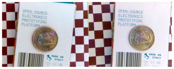
The RGB camera of the RealSense is a fixed-lens system designed for a range ≥200mm. As described above, this distance could be reduced to 100mm without degrading the depth information, so to maximize resolution and accuracy in all dimensions we aimed for a working range of 100–150mm. At these distances, the RGB image was fuzzy (Figure 2), which could impact accuracy during calibration, and hinder identification of individual termites. Focal distance on the RealSense cannot be adjusted, so instead we estimated the effective RGB focal length by observing image crispness, and calculated the additional lens curvature required to bring this down to the desired range, using the following lens equation:
| (1) |
where fD is the desired focal length, fN is the current focal length, fR is the focal length of the additional rectifying lens, and ε is the distance between the optical center of the two lenses. We conducted a preliminary stereo calibration within the recommended 200–1000mm range, to estimate the distance between the RealSense camera facing and the depth sensor plane. The discrepancy between the two was roughly 4mm, and the back focal distance of the existing lens can be calculated at 1.86mm, which gives a lower bound on ε of ≈ 2.1mm.
Figure 2.
RealSense RGB camera output without (left) and with (right) focal correction lens.
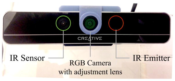
We assume a thin adjustment lens placed flush with the sensor casing, and adopt a conservative value of ε = 2.5mm to calculate the desired focal length of the adjustment lens. We chose a desired focal length of 135mm—roughly in the middle of our ideal working range. From Equation (1) we calculate a desired adjustment lens focal length of 228mm. Note that the lens is constrained geometrically by the IR camera and emitter on either side of the RGB camera (Figure 1), meaning that the overall size of the lens+housing could not exceed 20mm in diameter—this limited the available options among off-the-shelf lenses. A PCX condensor lens with a diameter of 15.6mm and a focal length of 222mm was sourced, significantly improving image crispness in the working range (Figure 2). This truncation of the optimum focal length naturally resulted in image blur at longer distances, so to maintain precision, images used for the new calibration (with lens) were restricted to a zone 100mm–500mm from the camera.
Figure 1.
The Intel RealSense (front view), with added lens.
2.2.2 Calibration of camera internals
Calibration toolboxes for two-camera IR depth-sensing systems exist ([1, 9]), but have been designed with the Kinect in mind. They usually involve simultaneously optimizing all depth/camera parameters using an external fixed camera to establish a ground truth via stereo RGB, while measuring raw depth values with the depth camera. Due to differences in the depth/disparity mapping and information encoding between Kinect and RealSense, and the high precision requirements of our application, these toolboxes were not well-suited. However, the Intel RealSense SDK provides access to the raw IR stream from the depth camera, allowing us to de-couple the calibration process, similar to the method described in [19]. We take a standard stereo calibration approach [17], using the raw IR camera stream and the RGB camera, which returns an accurate measure of both camera internals, the transformation between them, and the three-dimensional location of a flat calibration grid in a reference frame co-located with the depth camera. The depth/disparity can then be calculated independently of the depth camera internals. Note that printer ink can refract IR light, so the color value of the dark blocks on the calibration grid was chosen to ensure maximum possible contrast without loss of depth data.
The stereo camera calibration was conducted with the assistance of the Caltech Matlab camera calibration toolbox [2]. The short baseline between IR and RGB cameras is suboptimal for stereo calibration, hence it was necessary to use a high number of images, and ensure significant angular range representation in the calibration plate.
Table 1 gives sensor-specific values for the camera intrinsic parameters of one RealSense: fc (pixel-based focal length), cc (principal point), kc (image distortion co-efficients), and as an estimate of the frame transformation between the IR and RGB cameras. As with most modern cameras, the skew coefficient αc is found to be zero or negligible in both depth and RGB.
Table 1.
Comparison between manufacturer-supplied data and our re-calibrated estimates of intrinsic parameters, inter-camera transformation parameters, and depth-disparity mapping.
| Par. | Manufacturer | Our calibration |
|---|---|---|
|
| ||
| fcD | [475.63, 475.63] | [480.13, 479.72] ± [1.24, 1.23] |
| ccD | [311.13, 245.87] | [311.36, 250.10] ± [1.42, 0.95] |
| kcDr | [−0.140, −0.024, 0.017] | [−0.120, −0.030, 0] ± [0.004, 0.009, 0] |
| kcDt | [−0.0023, −0.0003] | [0.0022 0.0018] ± [0.0004, 0.0006] |
| om | [0.0047, 0.0010, 0.0042] | [0.0197, 0.0033, 0.0045] ± [0.0016, 0.0028, 0.0002] |
| t (mm) | [25.7, −0.162, 3.95] | [24.21, 0.356, −0.899] ± [0.0246, 0.0231, 0.1142] |
| a0 | 0 | −8.59 ± 0.365 |
| a1 | 0.125 | 0.143 ± 0.00025 |
These parameter estimates were noticeably distinct from the generalized values available from the manufacturer. Note the values in Table 1 are representative only; each sensor must be independently calibrated before use – but these calibration values are stable over the life of the sensor).
2.2.3 Estimation of depth/disparity mapping
We can now establish a ground truth to use for depth/disparity mapping. Again, while an estimate for this mapping is available from the manufacturer, it is not specific to the individual sensor. To eliminate potential confounding errors from imperfect homography estimations, we restricted the depth images used for estimating this mapping to those where the angle of the plate was close to parallel with the sensor plane.
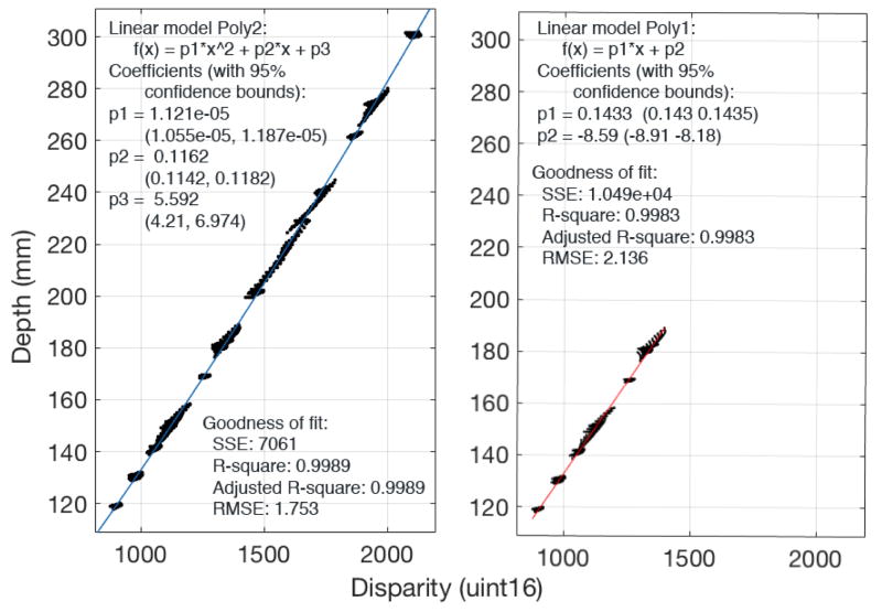
Unlike the Kinect [9] (and contrary to the values in the the RealSense manufacturer data), the depth/disparity mapping is slightly nonlinear even at ranges of <500mm (Figure 3), however by restricting the data to our expected experimental working range (<200mm) we find a linear fit is highly robust. For larger working ranges, the use of a nonlinear mapping may be preferable.
Figure 3.
Depth values calculated using a calibration plate vs the raw disparity values from the IR sensor. Left: fit for all data (excluding images with a highly angled calibration plate). Right: fit for only plate scans at <200mm depth.
Via linear regression, we obtain coefficients (a0, a1):
| (2) |
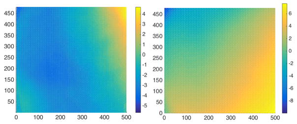
where z is the depth coordinate of a pixel at (i, j), in mm, d is the disparity registered at those pixel coordinates, and δ is an adjustment factor based on the residual error, dependent on pixel location within the image (see Figure 9, Results). Over short ranges, δ is highly stable, and hence can be approximated by a matrix of scalar constants (as is also true in the Kinect, see [9]). The coefficient values a0, a1 for a single SR300 depth sensor can be seen in Table 1.
Figure 9.
Residual error maps for two RealSense SR300 depth cameras (while three sensors were calibrated, two came from the same manufacturing batch, with very similar residual errors).
We obtained a value for δ by averaging the residual error in the depth data from scans of an orthogonal flat plate at known depths, restricted to a short distance within our intended working range (100–150mm). Note that at longer ranges, a new estimation of residual error is likely to be necessary, and the assumptions of δ constancy may not hold.
2.3. Rectification
To usefully visualize termite building activity, we need to rectify the depth scan to eliminate any rotation or translation introduced by the offset between the depth camera plane and the baseline plane of the arena of activity under study. We can construct a transformation between the RGB camera frame and the depth frame:
| (3) |
where xD, xRGB are the 3-dimensional positions of a point in the depth frame and RGB frame, respectively. To rectify the depth image, a calibration grid is placed at the ground-frame or base of the arena. The transformation between grid and camera plane is calculated using planar homography from the grid corners, and given by .
For each pixel pi;j in the depth scan, we use Equation (2) to calculate the depth in mm, resulting in a pixel-depth representation p′(i, j) = [i, j, zS(i, j)]. We calculate the normalized planar position of each pixel:
| (4) |
where cc, fc are the camera internal parameters found previously. We use the Oulu distortion model, as described in [7] and seen in the Caltech toolbox [2], to compensate for the radial and tangential distortion encapsulated in kcD. Let the undistorted plane coordinates be , then the mapping h: ℤ × ℤ × ℝ → ℝ3 between the pixel-depth representation and Cartesian coordinates can be found:
| (5) |
Using Equation (3), and the known transformation between color camera and plate , it is straightforward to rectify these coordinates such that the plane of interest of the scan is aligned with the depth camera plane:
| (6) |
Note that the z-component of the vector xD thus measures the height offset from the arena baseline plane, rather than distance from the camera plane.
2.4. Experimental Procedure
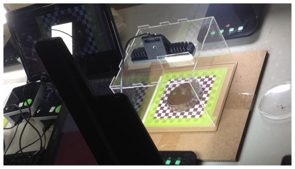
To record controlled build experiments, we required a fixed sensor at a known location, and consistent lighting with high attenuation in the IR spectrum. The experiment arena shown in Figure 4 was lit by two 550 lumen desklamps on opposite sides of the dish, using the coolest color temperature available (6500K), and enveloped in a diffuser to eliminate shadows. The sensor was fixed using a laser-cut 3D box with inserted supports, and the substrate was placed centrally within the dish, directly on top of a calibration grid (to ensure accurate reconstruction of the substrate baseline). We tested whether the sensor could accurately scan the build material (soil from a termite mound), the termites themselves, and whether the substrate provided (usually an off-the-shelf petri dish) interfered with with the IR pattern projection or detection1.
Figure 4.
Laser cut experimental box with cool-temperature high-lumen lighting setup (not pictured: light diffusion tent).
Neither termites nor soil showed significant interference with the sensor pattern. Petri dishes of plastic or glass reflect/refract IR wavelengths; however, since the interference is largely confined to the vertical rim of the dish, we simply ignored depth data at or beyond the dish rim.
The RealSense API provides an extensive array of high-level functions, and can record (compressed) RGB and IR frames using its native .rssdk format, but there is presently no way of guaranteeing the frames recorded are precisely synchronized. Instead, the Linux RealSense drivers were used to create a custom C++ interface for recording sequential frames in RGB and depth, synchronously or asynchronously, at any framerate up to 30fps (the maximum possible for high-resolution RGB with the current SR300). For high-speed recordings, hardware requirements were >3GHz processor, USB3.0 connector, 4th or 5th generation Intel processor, and 500GB+ memory – at lower framerates, a 2.5GHz processor will suffice.
Using this arrangement, we recorded termite early build experiments with Macrotermes michaelensi, at the Cheetah View Research Field Station near Otjiwarongo, Namibia.
2.5. Build Reconstruction
This system seeks to simultaneously track termites, and reconstruct mm-level soil deposits and excavations left by termite activity. Hence, we desire a 3D timeline of soil movement sans termites as well as high-resolution RGB frames for tracking.
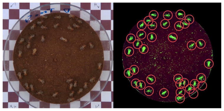
To eliminate insects from the 3D depth scans, we first identified the locations of the termites in the RGB frame using color, hue and saturation-based image segmentation, as seen in Figure 5. The termite centroids were then reprojected into the depth camera image plane.
Figure 5.
Left: High-resolution RGB image of petri dish, soil and termites. Right: Automatic termite detection based on image segmentation.
From the calibration plate placed under the termite arena, we know the distance between the arena baseline and the RGB camera plane, the soil depth at initialization, and the mean termite height. We can then produce an estimate of the 3D coordinates of each termite centroid in the RGB camera frame, as follows:
Let be a termite centroid location. We normalize this position:
| (7) |
then un-distort the set of normalized pixel coordinates { } using the known radial and tangential distortions kcRGB, as previously, to produce the set of undistorted pixel coordinates { }. The 3D termite coordinates are then:
| (8) |
where ze = zpl − Δs − th. zpl is the distance between arena baseline and camera plane, Δs is estimated soil height and th is mean termite height. The height of the soil around any particular termite location can be updated over the course of a build by projecting the mean height of the soil in the corresponding location in the depth scan back into the RGB camera frame, thus ensuring the estimate does not deviate too far from the reality. The 3D termite centroid is transformed into the depth camera frame using the known rotation and translation between cameras:
| (9) |
These coordinates are converted to a 2D pixel representation using the inverse of the pixel-3D projection method. Calculate the corresponding depth pixel coordinates :
| (10) |
Then we incorporate the distortion model of the depth camera established by the stereo calibration, as before [7]. The depth pixel coordinates can be calculated from the lens-distorted coordinates ( ) and internal parameters of the depth camera:
| (11) |
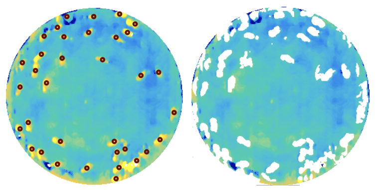
An example of reprojected termite centroid locations is shown in Figure 6 (left).
Figure 6.
Left: A rectified depth scan, corrected for residual error, with the reprojected termite centroids indicated by the red circles o. Steady-state noise effects, perhaps due to reflection from the petri dish, are observable on the lower right of the dish arena. Right: the same depth image with termites digitally removed.
Within the depth scan, we isolate a circular region around each centroid and apply a binary height-thresholding filter to find contiguous pixel regions {pt}k with a high probability of representing a termite. Let each projected termite centroid be the center of a circular region of depth pixels p(i, j) = [pi, pj]:
| (12) |
where rd is a suitable region-of-interest radius (in this case, approximately half the average termite length in pixels, as registered in a depth frame at a distance of 13cm). We then take an average depth value z̄k over the total number of pixels n within the region:
| (13) |
where Dk represents a contiguous region identified with termite tk and σ is a heuristic threshold dependent on insect physiology and sensor noise levels (we found σ = 0.3mm provided a good result for Macrotermes). Figure 6 (right) shows the same depth scan, with termite-identified regions removed. This is an aggressive removal strategy, as false positives are less problematic than false negatives.
To reconstruct the build, we subtract the depth values of each frame from the preceding. Pixels with depth changes above a noise threshold γ (γ= ±0.2mm) are replaced with the updated frame value iff a) they are not likely to be part of a termite and b) they remain unchanged for a period of m frames following the current frame under analysis. The latter condition eliminates changes due to false negatives in the termite detection, which may occur when the built terrain becomes uneven – this is effectively a simplified persistence filter, [24], as follows:
| (14) |
where ℬ represents the set of pixels that retain their new depth value across the persistence filter time window. These are assumed to be non-transient features and are retained in the reconstructed depth frame fn. The remaining pixels are assumed invariant from frame n − 1 to n. Effectively, each pixel in the filtered frame represents the ‘last known’ state of the build progression. A low-pass temporal smoothing filter mitigates remaining edge effects or transient pixels, and frame-averaged background subtraction taken before excavation/building has begun can be used to remove features not created or modified by the termites, such as imperfections in the soil substrate, or steady-state noise effects.
3. Results
By the methods above, we successfully resolved fine-scale three-dimensional structures using a low-cost, off-the-shelf IR-RGB sensor, up to framerates of 30Hz.
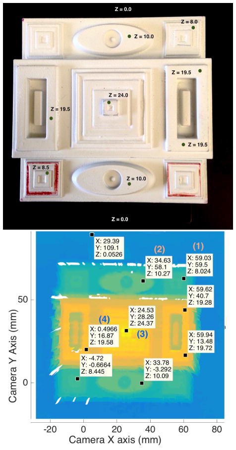
To assess the accuracy of our calibration, we created a 3D calibration block with single-axis symmetry, which incorporated positive and negative depth changes ranging from 10mm down to 0.1mm, and x–y features with varying widths down to 0.5mm. Figure 7 shows a photo of the 3D block (top), and a reconstruction using the depth camera (bottom), with corresponding height points marked on both. There is some variability in the returned values, likely due to sensor noise, but depth steps of 0.5(±0.3)mm can be resolved with confidence, as can features ≥ 0.5mm in the x–y plane. A quantitative comparison between the known plate dimensions, those calculated using manufacturer parameters, and those calculated using our new, re-calibrated parameters, is given in Table 2.
Figure 7.
3D calibration plate and corresponding depth scan. Depth has been rectified and projected into a 3D Cartesian plane coincident with the camera plane, for comparison purposes. Note that remapping the pixels (i, j) to a smooth surface in (x, y) causes interpolation smear at discontinuities – this is not an issue when working in pixel-depth coordinates (i, j, z). Depth shadows are observable around the plate verticals.
Table 2.
Comparison of true height, height estimation using manufacturer’s parameters, and height estimation using our recalibrated parameters. Due to the manufacturer assumption of α0 = 0, their baseplate depth estimate (zp) is significantly erroneous. Hence, to more clearly show discrepancies, Δz gives the height of selected points from the baseplate value, ie Δz = z − zp. The comparison points used correspond to (1), (2), (3), (4) in Figure 7.
| True depth | Manufacturer | Our calibration | |
|---|---|---|---|
|
| |||
| zp | 0 | 19.07 | 0.05 |
|
| |||
| Δz | 8.0 | 6.12 | 7.97 |
| 10.00 | 7.50 | 10.22 | |
| 24.0 | 17.09 | 24.32 | |
| 19.50 | 13.73 | 19.53 | |
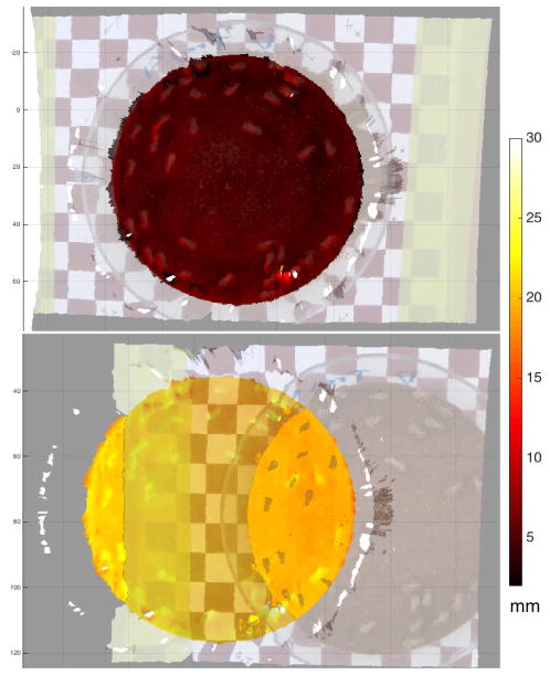
The re-calibrated depth and colour images can therefore be mapped to each other at a significantly greater accuracy than the manufacturer-provided automapping provided. Figure 8 shows a remapping of the RGB camera image into the depth camera frame. The scale on the right shows the estimated distance from the calibration plate at the base of the arena. Note that the arena base + soil height together are roughly 5mm.
Figure 8.
A 3D overlay of rectified depth data and RGB image data, using (top) our updated calibration values for both RGB and depth cameras, and (bottom) the manufacturer’s values.
Some variance was observed between sensors — for these experiments we fully calibrated three sensors from two different manufacturing batches, and while the transformation between depth and RGB cameras was similar for all (within uncertainty bounds) we found significant differences between cameras in depth-disparity mapping coefficients (ā0 = 8.303 ± 2.200, ā1 = 0.140 ± 0.010) and residual errors, as shown in Figure 9.
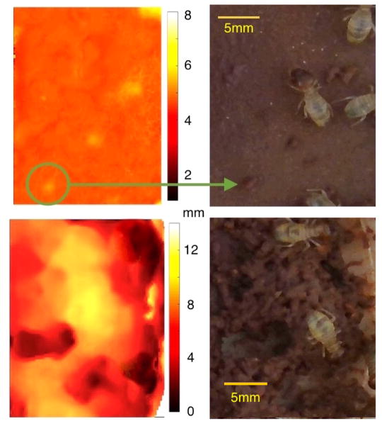
By applying our more precise calibration values and using the combined RGB-D information to identify and project termite locations, we could not only precisely track individual termites, but also ‘remove’ virtually all termites from video of the Macrotermes early-stage build process, leaving us with a high-speed reconstruction of the build activity in three dimensions, e.g. Figure 10.
Figure 10.
Snapshots from two small areas of a dish during a long-term termite build sequence. Left, reconstructed build depth images with termites removed; right, raw RGB images. Colour scaling has been adjusted to feature size, in order to highlight both single depositions (green circle/arrow, top image) and larger scale builds (bottom image). Initial soil height was approximately 5mm above the baseline (lower values represent excavation).
4. Discussion
This paper demonstrates a low-cost, portable, high-resolution 3D scanning system using off-the-shelf components, which can be applied to any close-range application. The depth sensor can accurately report structural changes down to 1.0 (±0.3) mm, which compares favorably with other 3D reconstruction hardware (e.g. laser scanners and range-finders). This system is particularly suited for applications where both high accuracy and high speed are vital, and it can also, with the aid of extended RGB-D imaging, filter out objects outside of the domain of inquiry. Combining RGB and depth could also improve reconstruction precision and tracking accuracy. Preliminary tests suggests these results may transfer to outdoor reconstruction, potentially providing a low-cost 3D sensing system for the field.
One impediment to domain transferability is the application-specific adjustments required when reconstructing depth data (e.g. distance-dependent residual error mapping). Particularly for high-precision tasks close to the camera, approximations that may work sufficiently well at longer ranges become invalid. However, if the sensor limitations are well-understood and care is taken to reduce or eliminate potential confounding factors in the experimental stage, the solution described here is versatile and can be applied across other domains, such as dynamic deformation of objects, or precision expression recognition.
Supplementary Material
Acknowledgments
Research reported in this publication was supported by the National Institute Of General Medical Sciences of the National Institutes of Health under award number R01GM112633. The content is solely the responsibility of the authors and does not necessarily represent the official views of the National Institutes of Health.
Footnotes
This paper has supplementary material available, provided by the authors. This includes sample scans of dish and 3D printed material, images of termite construction in RGB and depth, videos of the build process with termites removed, and a readme file.
References
- 1.Blanco JL. [accessed 10-Sept-2016];Kinect stereo calibration. http://www.mrpt.org/list-of-mrpt-apps/application-kinect-stereo-calib. Online.
- 2.Bouguet J-Y. Camera calibration toolbox for matlab. http://www.vision.caltech.edu/bouguetj/calibdoc/index.html.
- 3.Digumarti ST, Chaurasia G, Taneja A, Siegwart R, Thomas A, Beardsley P. Underwater 3D capture using a low-cost commercial depth camera. 2016 IEEE Winter Conference on Applications of Computer Vision (WACV); IEEE; 2016. pp. 1–9. [Google Scholar]
- 4.Freedman B, Shpunt A, Machline M, Arieli Y. Depth mapping using projected patterns. 8,150,142 US Patent. 2012 Apr 3;
- 5.Green B, Bardunias P, Turner S, Nagpal R, Werfel J. Excavation and aggregation as organizing factors in de novo construction by mound-building termites. Pending. doi: 10.1098/rspb.2016.2730. In submission. [DOI] [PMC free article] [PubMed] [Google Scholar]
- 6.Han J, Shao L, Xu D, Shotton J. Enhanced computer vision with Microsoft Kinect sensor: A review. IEEE Transactions on Cybernetics. 2013;43(5):1318–1334. doi: 10.1109/TCYB.2013.2265378. [DOI] [PubMed] [Google Scholar]
- 7.Heikkila J, Silvén O. A four-step camera calibration procedure with implicit image correction. Computer Vision and Pattern Recognition, 1997. Proceedings., 1997 IEEE Computer Society Conference on; IEEE; 1997. pp. 1106–1112. [Google Scholar]
- 8.Henry P, Krainin M, Herbst E, Ren X, Fox D. RGB-D mapping: Using Kinect-style depth cameras for dense 3D modeling of indoor environments. The International Journal of Robotics Research. 2012;31(5):647–663. [Google Scholar]
- 9.Herrera D, Kannala J, Heikkilä J. Joint depth and color camera calibration with distortion correction. IEEE Transactions on Pattern Analysis and Machine Intelligence. 2012;34(10):2058–2064. doi: 10.1109/TPAMI.2012.125. [DOI] [PubMed] [Google Scholar]
- 10.MakerBot. [accessed 5-May-2016];Makerbot digitizer user manual. https://s3.amazonaws.com/downloads-makerbot-com/digitizer/MakerBotDigitizerUserManual.pdf. Online.
- 11.Mersch DP, Crespi A, Keller L. Tracking individuals shows spatial fidelity is a key regulator of ant social organization. Science. 2013;340(6136):1090–1093. doi: 10.1126/science.1234316. [DOI] [PubMed] [Google Scholar]
- 12.Microsoft Windows Dev Center. [accessed 24-Apr-2016];Kinect hardware. https://developer.microsoft.com/. Online.
- 13.Noldus LP, Spink AJ, Tegelenbosch RA. Computerised video tracking, movement analysis and behaviour recognition in insects. Computers and Electronics in Agriculture. 2002;35(2):201–227. [Google Scholar]
- 14.Paulus S, Schumann H, Kuhlmann H, Léon J. High-precision laser scanning system for capturing 3D plant architecture and analysing growth of cereal plants. Biosystems Engineering. 2014;121:1–11. [Google Scholar]
- 15.Ramieri G, Spada M, Nasi A, Tavolaccini A, Vezzetti E, Tornincasa S, Bianchi S, Verzé L. Reconstruction of facial morphology from laser scanned data. Part I: reliability of the technique. Dentomaxillofacial Radiology. 2014 doi: 10.1259/dmfr/43516583. [DOI] [PubMed] [Google Scholar]
- 16.Rautaray SS, Agrawal A. Vision based hand gesture recognition for human computer interaction: A survey. Artificial Intelligence Review. 2015;43(1):1–54. [Google Scholar]
- 17.Scaramuzza D, Martinelli A, Siegwart R. A tool-box for easily calibrating omnidirectional cameras. 2006 IEEE/RSJ International Conference on Intelligent Robots and Systems; IEEE; 2006. pp. 5695–5701. [Google Scholar]
- 18.Schneider CW, Tautz J, Grünewald B, Fuchs S. RFID tracking of sublethal effects of two neonicotinoid insecticides on the foraging behavior of Apis mellifera. PloS ONE. 2012;7(1):e30023. doi: 10.1371/journal.pone.0030023. [DOI] [PMC free article] [PubMed] [Google Scholar]
- 19.Smisek J, Jancosek M, Pajdla T. Consumer Depth Cameras for Computer Vision. Springer; 2013. 3D with Kinect; pp. 3–25. [Google Scholar]
- 20.Strait S, Smith N, Penkrot T. The promise of low cost 3D laser scanners. Journal of Vertebrate Paleontology. 2007;27:153A. [Google Scholar]
- 21.Su X, Zhang Q. Dynamic 3-D shape measurement method: A review. Optics and Lasers in Engineering. 2010;48(2):191–204. [Google Scholar]
- 22.Surmann H, Nüchter A, Hertzberg J. An autonomous mobile robot with a 3D laser range finder for 3D exploration and digitalization of indoor environments. Robotics and Autonomous Systems. 2003;45(3):181–198. [Google Scholar]
- 23.Webster D, Celik O. Systematic review of Kinect applications in elderly care and stroke rehabilitation. Journal of Neuroengineering and Rehabilitation. 2014;11(1):1. doi: 10.1186/1743-0003-11-108. [DOI] [PMC free article] [PubMed] [Google Scholar]
- 24.Wright JN, Plugge JS, Fash DG, III, Langdon DR, Finger DJ, Normand BM, Guracar IM. Adaptive persistence processing. 5,595,179 US Patent. 1997 Jan 21;
Associated Data
This section collects any data citations, data availability statements, or supplementary materials included in this article.


