Abstract
Microfluidic devices can form double emulsions with uniform properties, but require cumbersome fabrication steps to pattern their wettability. We demonstrate spatially-controlled plasma oxidation to create wettability patterns for forming double emulsions. Our method performs comparably to chemical techniques but is simpler, more reliable, and scalable to patterning large arrays of drop makers.
Graphical abstract
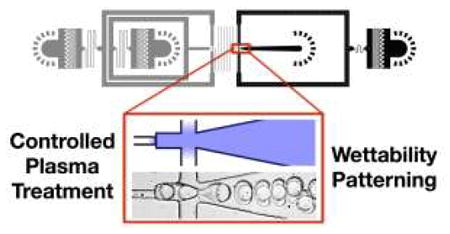
Spatially-controlled plasma treatment enables easy, accurate, reliable and scalable wettability patterning of microfluidic devices.
Double emulsions consist of a liquid core encapsulated within an immiscible shell, dispersed in a carrier fluid.1-4 The core-shell structure of these emulsions make them valuable for applications ranging from encapsulating chemicals to acting as structural templates for particles and capsules in the food, cosmetic, and pharmaceutical industries.4-9 Microfluidic devices are particularly effective for forming double emulsions because they afford unmatched control over droplet dimensions while also enabling efficient encapsulation of active compounds.6, 10-16 However, the devices can be difficult to fabricate, requiring careful control of device wettability to enable encapsulation of the hydrophilic and hydrophobic phases.11, 15, 18-20
At the size scales of microfluidic channels, wettability is crucially important for dictating the type of emulsion formed. Hydrophilic channels, for instance, form “direct” emulsions consisting of oil droplets dispersed in water (OW), while hydrophobic channels form “inverted” emulsions of water droplets in oil (WO).21, 22 Because double emulsions comprise droplets of both types, wettability must be carefully controlled. Coaxial flow focusing reduces the importance of channel wettability by preventing the dispersed phases from touching the channel walls using sheath flow; this enables formation of either type of emulsion irrespective of channel wettability.16, 23, 24 The high flow rate of sheath required, however, is wasteful of carrier phase, making the process inefficient. Double emulsification methods based on “confined” droplet generation, such as sequential T-junctions or flow-focusing, are more efficient but require spatially-patterned wettability.11, 12, 15, 18, 19, 25 This enables direct emulsification in a hydrophilic region and inverted emulsification in a hydrophobic region, to form either water-in-oil-in-water (WOW) or oil-in-water-in-oil (OWO) double emulsions.
A challenge of implementing these techniques, however, is that patterning channel wettability requires cumbersome fabrication steps. Most methods, for example, require that devices be filled with liquid chemicals to treat certain regions but not others, such as UV-initiated polymer grafting, polyelectrolyte layering, or corona discharge with a blocking phase.18, 19, 25-27 Methods using plasma formed inside sealed devices are promising in that the plasma can be controlled and guided by inserted or patterned electrodes.28-31 While these methods are effective for wettability patterning, the need to carefully introduce fluids into the device is tedious, labour intensive, and prone to failure. Moreover, each device must be patterned individually, making simultaneous patterning of droplet makers challenging, as needed for scale-up.32, 33 To enable simple, reliable, and scalable wettability patterning, an optimal method would utilize a uniform treatment that did not require the introduction of liquids into the device.
In this paper, we demonstrate a simple, reliable, and scalable method for patterning microfluidic device wettability. When exposed to oxygen plasma, hydrophobic polymer channels can be made hydrophilic,34-36 the channels closest to the inlet ports becoming hydrophilic more quickly than ones deeper inside since ionized oxygen species can diffuse more readily into these regions. By integrating diffusion barriers in the form of narrow channels at strategic locations and controlling plasma oxidation time, we can select which regions become hydrophilic and which remain hydrophobic, thereby generating a desired wettability pattern. This novel surface modification technique enables fabrication of devices for forming monodisperse WOW or OWO double emulsions. Moreover, since the obtained pattern is dictated by the channel geometry and plasma oxidation time, both of which can be controlled precisely, the method yields a reliable pattern in every device exposed to the plasma. This enables easy, accurate, and reliable patterning of large numbers of microfluidic devices.
Materials and Methods
Device fabrication and patterning
The devices are fabricated in PDMS using soft lithography.37 SU-8 masters are fabricated using photolithography and used to mould PDMS devices. Holes are punched at inlet and outlet ports using a 0.75-mm biopsy punch (Harris, Uni-Core 0.75) and the channel side of the PDMS slab is cleaned with scotch tape to remove residual particles. The PDMS devices are bonded to flat PDMS substrates by treating with oxygen plasma for 60 s at 1 mbar of pressure in a plasma cleaner (Harrick Plasma, PDC-001). The bonded device is baked at 65°C for 48 hours to completely revert the wettability back to its native hydrophobicity.38 To wettability pattern the device, select inlet ports are blocked with scotch tape, leaving the ports near the regions to be treated open to oxygen plasma treatment at 1 mbar of pressure for 0.5 to 3 minutes, depending on the layout and desired pattern. The wettability pattern is stable for a few hours at room temperature when the channels are exposed to air, but is slowly lost as the PDMS reverts back to its native hydrophobic state. The pattern can be maintained for longer durations by storing the devices filled with water or implementing solvent-extraction techniques.34, 35, 39, 40 They can also be treated repeatedly to regain a reverted pattern.
Surface characterization
Two visualization methods are used to visualize wettability patterns inside microchannels after plasma treatment: (a) adsorption test with dye-labeled proteins and (b) breath vapor condensation test. To enable access to the inner surfaces of the devices, the PDMS-to-PDMS bonding step (Fig. 1, Steps 1 and 2) is omitted and the two slabs is attached via unbonded adhesion. After plasma wettability patterning (Fig. 1, Steps 3 and 4), the slabs are disassembled and the bottom flat substrate is subjected to the visualization tests. For the adsorption test, the surface is stained with 0.1 mg/mL Alexa 647-labeled bovine serum albumin (Life Technologies, A34785) in PBS 7.2 for 10 s, washed with water, cleaned with scotch tape, and imaged with a fluorescence microscope (Life Technologies, EVOS FL Auto) using a filter set for Cy5. For the breath vapor condensation test, human breath is applied to the surface and the nucleation pattern of breath vapor condensation imaged with the same microscope using the transmitted light microscopy mode; imaging must occur rapidly as the aqueous droplets evaporate ~10 s.
Fig. 1.
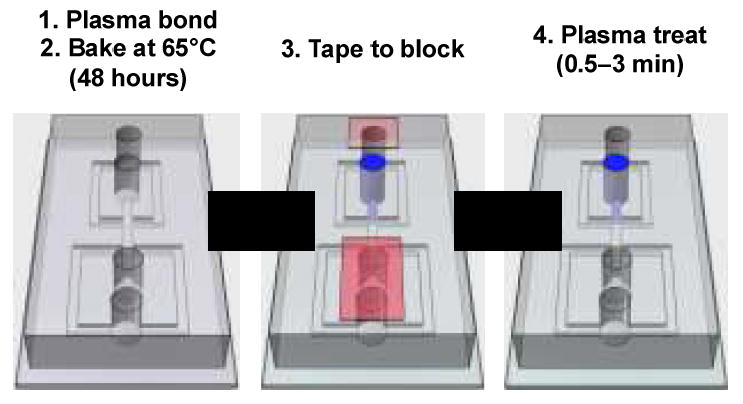
Fabrication steps for plasma wettability patterning. The device consists of a PDMS slab cast with microchannel structures bonded to a flat PDMS substrate. The chip is bonded by oxygen plasma treatment and baked for 48 hours to revert wettability back to hydrophobicity. Scotch-tape (red) is used to block plasma from entering certain inlet ports, while others are left open (blue). Oxygen species generated by the plasma diffuse into the open inlets, treating the channels near them to make them hydrophilic while leaving blocked channels hydrophobic. In this way, we are able to guide the plasma oxidation to achieve a desired wettability pattern.
Chemicals
We use hydrofluoroether (HFE; 3M™ Novec™ 7500) as the oil phase to avoid PDMS swelling upon contact. Surfactants are also added to prevent coalescence and optimize interfacial tension for droplet formation: (a) carboxylated perfluoropolyether (PFPE; DuPont™ Krytox™ 157-FSH) after deprotonation, and nonionic fluorosurfactant (008-FluoroSurfactant from RAN Biotechnologies) for HFE, the oil phase; (b) sodium dodecyl sulfate (SDS), Tween 20, Pluronic™ F-68 (Gibco) and poly(ethylene glycol) (PEG6k and PEG35k for average MW 6000 and 35000, respectively) for the aqueous phase. For WOW emulsions, the following solutions are used: inner phase (4% (v/v) Tween 20, 4% (w/v) PEG6k, 50 mM KCl, 20 mM Tris pH 8 in water), middle phase (2% (w/w) 008-FluoroSurfactant in HFE) and outer phase (4% (v/v) Tween 20, 1% (v/v) Pluronic F-68, 10% (w/v) PEG35k in water). For OWO droplets, inner phase (HFE), middle phase (2% (w/v) SDS in water) and outer phase (2% (w/v) PFPE in HFE are used. All chemicals are purchased from Sigma-Aldrich unless noted otherwise.
Device operation and data analysis
Immediately after the chip is plasma treated for wettability patterning, solutions are loaded into plastic syringes (BD 1mL Luer-Lok™ syringe and 27G ½ needle) and connected to the inlets via polyethylene tubing (SCI, PE/2, ID 0.38 mm, OD 1.09 mm). Computer-controlled syringe pumps (New Era Pump Systems, NE-501) o inject fluids at controlled volumetric flow rates. Liquid filling and droplet formation are monitored on a microscope equipped with a short-shutter camera (Unibrain, Fire-i 530b). To record drop formation videos, a high-speed camera (Vision Research, Miro M110) is used. Double emulsions are collected and transferred to a chambered slide (Invitrogen, C10283) and imaged using an EVOS microscope. Droplet sizes are characterized using the measurement annotation tools provided in the microscope software.
Results and Discussion
During plasma treatment, ionized oxygen species generated by the electric field bombard the surfaces of the device, resulting in oxidation that can render natively hydrophobic PDMS surfaces hydrophilic34, 35. To treat channels within the device, oxygen species must diffuse into the channels through open inlet ports. To spatially guide oxidation and generate a wettability pattern, we thus implement two strategies: 1) we block inlet ports near channels we want to remain hydrophobic with tape, preventing plasma from entering them, and 2) we add diffusion barriers in the form of channel constrictions to limit diffusion of radicals from treated regions into regions we want to remain untreated. The plasma oxidation time must be chosen to obtain the desired hydrophilicity in certain regions while maintaining hydrophobicity in others. This is easiest achieved by testing each design to identify the optimal time. A schematic illustration of the plasma patterning approach is shown in Fig. 1.
To characterize wettability patterns generated by our approach, we visualize the channels with fluorescently labeled proteins or a breath vapor condensation test. In the breath condensation test,41-43 the vapor in human breath condenses into water droplets upon contacting the PDMS surface, forming bigger droplets in regions that are hydrophilic and smaller droplets in ones that are hydrophobic (Fig. 2a and yellow inset). When viewed at lower magnification, the higher scattering of the small droplets makes the hydrophobic regions appear dark due to lower light transmission, while the comparatively lower scattering of the large droplets make the hydrophilic regions appear brighter; this allows clear visualization of the wettability pattern, as shown in Fig. 2b-d, upper panels. In this device (Fig. 2a, left), the outlet and carrier-phase inlets are left open and exposed to the plasma, while the inlets (not shown) are blocked. Consequently, the plasma begins converting the regions closest to the outlet and carrier inlet to hydrophilic with a pattern that encroaches deeper into the device as the plasma oxidation time is increased (10-180 s, Fig. 2b-d, upper). We corroborate these results by also performing a protein adsorption test with fluorescently-labeled bovine serum albumin (BSA). This protein has a net positive charge, causing it to adhere to negatively-charged plasma treated PDMS surfaces, allowing fluorescence visualization of the wettability pattern, Fig. 2b-d, lower panels. Both tests confirm that wettability becomes hydrophilic with plasma treatment and that as the treatment time increases, the plasma penetrates deeper into the device, allowing control of the wettability pattern with diffusion barriers and plasma time. In addition, the progressive nature of plasma patterning observed here shows that microplasma formation within the channel is negligible and the plasma does appear to be diffusing from the bulk chamber into the channel, which can be efficiently blocked by taping ports or slowed down by making channels narrower. While the fluorescently-labeled protein adsorption test provides good sensitivity, the breath vapor deposition test is fast and simple.
Fig. 2.
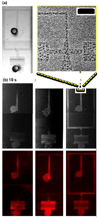
Visualization of wettability patterns after plasma treatment. (a) A light microscopy image of the WOW double emulsion device, which corresponds to the lower part of the design shown in Fig. 3a. The dark circles show punched holes where plasma can enter the sealed channels. (b-d) Transmitted light (top) and fluorescence (bottom) images after specified duration of plasma treatment. The progression of hydrophilic conversion of the surface over time can be observed using a water nucleation pattern generated by condensing breath vapour, or adsorption pattern of dye-labelled proteins. The inset (yellow box) shows a magnified view of the condensed droplets from breath vapour (scale bar, 100 μm).
An important example in which wettability patterning is essential is the generation of double emulsions in planar microfluidic devices.11, 15, 18, 19 Since surface wettability dictates the polarity of the emulsion formed, double emulsions comprising WO and OW droplets require two junctions with opposite wettability.11, 18, 19 To generate WOW double emulsions, the first junction forming the WO emulsion must be hydrophobic and the second forming the OW emulsion hydrophilic. To generate this wettability pattern, we design the device with a wide, short outlet, enabling rapid diffusion of oxygen radicals into the second junction. We block the inlets for the inner and middle phases with tape (upper two ports, Fig. 3a), and leave the carrier phase inlet and outlet exposed (lower two ports, Fig. 3a). During plasma treatment, ionized oxygen species readily diffuse into the second junction and convert it to hydrophilic, as shown in Fig. 3a. Connecting the two junctions is a long, narrow channel that limits diffusion of radicals from the second into the first junction. By choosing an oxidation time of 1–3 min, we are able to convert the second junction to hydrophilic while maintaining the upper junction hydrophobic, thereby obtaining the wettability pattern needed for forming WOW double emulsions, Fig. 3b.
Fig. 3.
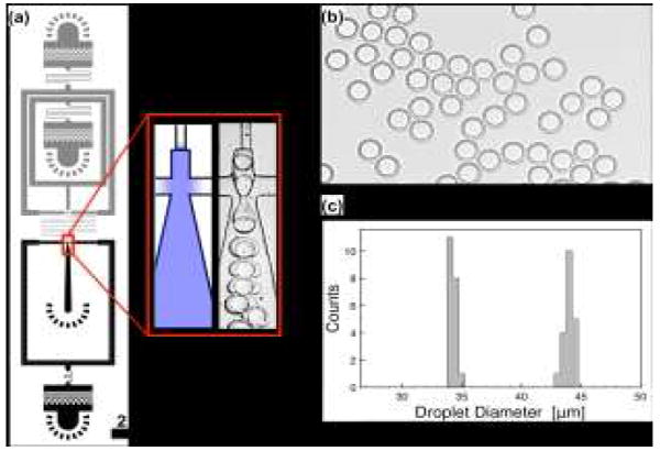
Generation of WOW double emulsion droplets. Generating WOW double emulsions uses serial drop makers in which the first is hydrophobic and the second hydrophilic, (a). The heights for the grey and black channels are 15 and 30 μm, respectively. The blow-up shows the region modified to be hydrophilic (blue) and a high-speed image of drop formation. Aqueous and oil introduced into the first junction form a WO single emulsion that flows into the second junction, where additional aqueous is added; this, combined with the hydrophilic wettability, leads to engulfment of the oil phase in the aqueous carrier, generating monodisperse WOW double emulsions, (b). The diameters of the inner and outer droplets exhibit narrow size distributions (c)
A property of our wettability patterning technique is that the wettability transitions gradually from hydrophilic to hydrophobic between the treated and untreated regions. Hence, the WO droplets generated by the first junction of our device flow over hydrophobic, then intermediate, then hydrophilic channels as they approach the second junction. As in microfluidic devices patterned with chemical methods, the ability of water droplets to flow over hydrophilic channels without coalescing on the walls depends on the properties of the solvents and surfactants that comprise the emulsion. For our fluorinated solvents and surfactants, which are valuable for performing biological assays in the emulsions,44, 45 the WO droplets are able to flow over hydrophilic walls without wetting, allowing us to generate uniform double emulsions with standard deviation in the inner and outer droplet diameters of less than 0.95% (n = 20), as shown in Fig. 3c.
Generating double emulsions of the opposite polarity (OWO) can be achieved by flipping the wettability pattern, making the first junction hydrophilic and the second hydrophobic. To make the first hydrophilic, we design another device in which the innermost inlet is wide and short, facilitating rapid diffusion of oxygen radicals into the first junction; connecting the two junctions we again use a narrow channel to limit diffusion into the second junction, as shown in Fig. 4a. To treat the device, we block the continuous and outlet ports with tape and leave the middle and inner phase inlets exposed, plasma treating for 30 s. This renders the first junction hydrophilic while maintaining the second hydrophobic, enabling generation of monodisperse OWO double emulsions, as show in Fig. 4b. The coefficients of variation for the inner and outer droplet diameters are < 2. 5% (n = 20; Fig. 4c).
Fig. 4.
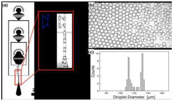
Generation of OWO double emulsion droplets. Forming OWO double emulsions requires two serial junctions like the WOW system, except that the wettability pattern must be flipped so that the first junction is hydrophilic and the second hydrophobic, (a). This leads to generation of OW droplets in the first junction that are encapsulated into monodisperse OWO double emulsions in the second junction, (b), which exhibit narrow inner and outer droplet diameter distributions, (c).
An important parameter when applying plasma-based wettability patterning is choosing a treatment time that converts select regions to hydrophilic while maintaining others hydrophobic. To investigate how plasma oxidation time impacts wettability pattern, we vary treatment time of the WOW double emulsion device and test its performance (Fig. 5). For a short treatment of 10 s, the first junction is sufficiently hydrophobic to form WO droplets, but the second is insufficiently hydrophilic to form OW droplets; instead, the middle oil phase wets the walls, causing it to flow as a parallel stream with the aqueous carrier phase, yielding no double emulsions (Fig. 5). When we increase plasma oxidation to 35 s, we observe the generation of double emulsions; however, they are large and contain multiple water-droplets. This is due to the intermediate wettability of the second junction, which is unable to rapidly lift the oil from the walls before it moves into the expanded lower channel. Since the size of droplets formed by a drop maker is proportional to the channel size,46 forming the double emulsions in the wide channel leads to large droplets containing many cores, as shown in Fig. 5. When we increase the patterning time to 60 s, the outlet is made more hydrophilic, enabling immediate engulfment of the oil in the second junction and, because the channel is narrow there, generation of small double emulsions with one core, as shown in Fig. 5. While this treatment time enables formation of monodisperse double emulsions with the desired number of cores, the wettability pattern wears off after just ~30 min. By increasing treatment time to 180 s, we are able to form the desired double emulsions while also making the device functional for ~3 hours. Increasing treatment time further does not substantially increase the lifetime of the pattern.
Fig. 5.
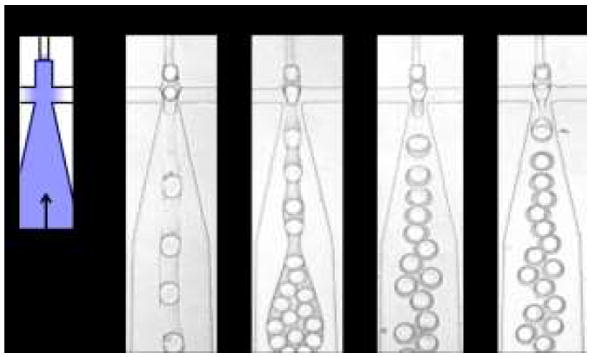
Effect of plasma treatment duration on double emulsion generation. Short plasma treatment times result in channels with intermediate wettability that are unable to form double emulsions (10 s), while longer treatment times yield more hydrophilic channels that yield small, monodisperse double emulsions (60 s). While the 60 s plasma treatment wears off after ~30 min, the 180 s treatment is stable for ~3 hrs, providing longer useful operation time. Flow rates used are the same for all conditions: 80, 80 and 250 μL/hr for inner, middle and outer phases, respectively.
Plasma-based wettability patterning enables formation of WOW and OWO double emulsions. To further investigate how devices patterned with this method compare with those patterned using chemical methods, we vary the droplet generation parameters and observe the effects on the double emulsion morphology. At low-to-moderate capillary number, droplet generation in “confined” geometries is dominated by interfacial stresses and proceeds through a plugging and squeezing mechanism.46-48 In this regime, the volumes of the droplets formed are proportional to the ratio of the inner and outer phase flow rates. When forming double emulsions using sequential droplet generators, the core droplet volume can be adjusted by varying the ratio of the inner (Q1) and middle (Q2) phases while holding the carrier phase (Q3) and Q1 + Q2 constant. To illustrate this, we vary Q1/Q2 and measure the corresponding change in droplet volume. The inner droplet volume increases in proportion to the flow rate ratio while the outer droplet volume remains constant, as shown in Fig. 6. This demonstrates that the inner droplet dimensions can be adjusted independently of the other droplet dimensions by appropriately varying flow rates, in concordance with double emulsification devices patterned using chemical techniques.
Fig. 6.
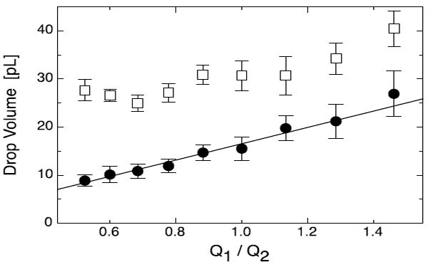
Control of core droplet volume. When forming WOW double emulsions with our device, the core droplet volume (black circle, ●) is proportional to the ratio of the inner and middle phase flow rates Q1/Q2, but the outer droplet volume (white square, □) is roughly constant. The symbols are averages and the error bars standard deviations from 15 droplet measurements. The solid line shows the best fit using the equation V = a + b Q1/Q2, the expectation based on plugging droplet generation. At high ratios the outer droplet volume tracks the inner droplet volume, which is due to the inner droplet triggering the generation of the outer droplet.17
Wettability-patterned double emulsion generators enable variation of the inner droplet volume holding the outer droplet volume constant; they also enable adjustment of outer droplet volume holding inner droplet volume constant by varying the flow rate ratio in the second junction. To illustrate this, we set Q1 and Q2 constant at 50 and 65 μL/hr, respectively, Q3 and to 50 μL/hr. At these flow rates, the ratio of (Q1 + Q2)/Q3 is large, yielding large double emulsions containing multiple cores, as shown in Fig. 7. As we increase Q3 while holding Q1 and Q2 constant, we reduce the flow rate ratio in the second junction, reducing outer droplet volume and the number of cores. Interestingly, while the number of cores decreases rapidly as a function of Q3 for 50–100 μL/hr, it is roughly constant for 100–170 μL/hr. This is because at these flow rates the outer droplets are of a similar size to the inner droplets so that the inflow of inner droplets affects the generation of the outer droplets, causing the droplet cycles to synchronize so that every double emulsion contains two cores.17 As Q3 is increased further, the outer droplets become even smaller and form more rapidly; this results in a transition flow rate in which the number of cores oscillates between 1 and 2, settling at exactly 1 core per double emulsion for Q3 > 180 μL/hr, as shown in Fig. 7. At even higher Q3, the generation alternates between single-core double emulsions and empty oil droplets. This demonstrates that the outer droplet volume can be varied independently of the core droplet volume, consistent with double emulsion generators patterned using chemical methods.
Fig. 7.
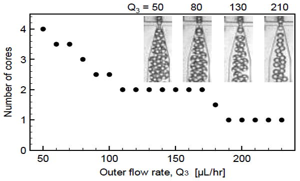
Control of number of core phase drops. For the WOW double emulsion device, holding Q1 and Q2 constant while changing Q3 varies the flow rate ratio in the second junction, leading to variation of the absolute size of the double emulsions and, consequently, the number of core droplets encapsulated. The plotted values are the averages from two independent measurements.
Conclusions
We have presented a simple and reliable method for patterning microfluidic device wettability using channel-guided plasma oxidation. Our method can pattern large arrays of droplet makers in parallel and, as we have shown, reliably yields patterns for generating monodisperse double emulsions comparable to devices patterned with more cumbersome chemical techniques. In addition, the unique ability of our method to pattern large numbers of devices in parallel should facilitate the fabrication of arrayed devices, to scaled-up double emulsification. Our method should also enable generation of complex patterns that are difficult or impossible to create with techniques requiring the injection of liquid chemicals and blocking phases. This approach can be extended to patterning microdevices made of other polymeric materials that are known to be amenable to plasma treatment for surface modification.
Acknowledgments
We thank Jimin Park for help with 3d graphics. This work was funded by an NSF CAREER Award (DBI-1253293), the NIH New Innovator Award (1DP2AR068129-01) and R01 (1R01EB019453-01), and the Defence Advanced Research Projects Agency (HR0011-12-C-0065, N66001-12-C-4211, DE-AC02-05CH11231).
Footnotes
Electronic Supplementary Information (ESI) available: [details of any supplementary information available should be included here]. See DOI: 10.1039/c000000x/
Notes and references
- 1.Yang Y-Y, Chung T-S, Ng NP. Biomaterials. 2001;22:231–241. doi: 10.1016/s0142-9612(00)00178-2. [DOI] [PubMed] [Google Scholar]
- 2.Pistel K, Kissel T. Journal of microencapsulation. 2000;17:467–483. doi: 10.1080/026520400405723. [DOI] [PubMed] [Google Scholar]
- 3.Garti N. Colloids and Surfaces A: Physicochemical and Engineering Aspects. 1997;123:233–246. [Google Scholar]
- 4.Garti N, Bisperink C. Current opinion in colloid & interface science. 1998;3:657–667. [Google Scholar]
- 5.Garti N. LWT-Food Science and Technology. 1997;30:222–235. [Google Scholar]
- 6.Maa Y, Hsu C. Journal of microencapsulation. 1997;14:225–241. doi: 10.3109/02652049709015335. [DOI] [PubMed] [Google Scholar]
- 7.Yoneyama T, Matsuoka Y, Suzuki H, Kumagai S, Takada S. Google Patents. 1994 [Google Scholar]
- 8.Figueroa R, Jr, Harrison BG, Jr, SaNogueira JP. Google Patents. 1990 [Google Scholar]
- 9.Skurtys O, Aguilera J. Food Biophysics. 2008;3:1–15. [Google Scholar]
- 10.Stone H, Leal L. Journal of Fluid Mechanics. 1990;211:123–156. [Google Scholar]
- 11.Okushima S, Nisisako T, Torii T, Higuchi T. Langmuir. 2004;20:9905–9908. doi: 10.1021/la0480336. [DOI] [PubMed] [Google Scholar]
- 12.Nisisako T, Okushima S, Torii T. Soft Matter. 2005;1:23–27. doi: 10.1039/b501972a. [DOI] [PubMed] [Google Scholar]
- 13.Chen CH, Abate AR, Lee D, Terentjev EM, Weitz DA. Advanced materials. 2009;21:3201–3204. [Google Scholar]
- 14.Shah RK, Shum HC, Rowat AC, Lee D, Agresti JJ, Utada AS, Chu L-Y, Kim J-W, Fernandez-Nieves A, Martinez CJ. Materials Today. 2008;11:18–27. [Google Scholar]
- 15.Abate A, Weitz D. Small. 2009;5:2030–2032. doi: 10.1002/smll.200900569. [DOI] [PubMed] [Google Scholar]
- 16.Utada A, Lorenceau E, Link D, Kaplan P, Stone H, Weitz D. Science. 2005;308:537–541. doi: 10.1126/science.1109164. [DOI] [PubMed] [Google Scholar]
- 17.Abate AR, Rotem A, Thiele J, Weitz DA. Physical Review E. 2011;84:031502. doi: 10.1103/PhysRevE.84.031502. [DOI] [PubMed] [Google Scholar]
- 18.Abate AR, Thiele J, Weinhart M, Weitz DA. Lab on a Chip. 2010;10:1774–1776. doi: 10.1039/c004124f. [DOI] [PubMed] [Google Scholar]
- 19.Abate AR, Krummel AT, Lee D, Marquez M, Holtze C, Weitz DA. Lab on a Chip. 2008;8:2157–2160. doi: 10.1039/b813405g. [DOI] [PubMed] [Google Scholar]
- 20.Seo M, Paquet C, Nie Z, Xu S, Kumacheva E. Soft Matter. 2007;3:986–992. doi: 10.1039/b700687j. [DOI] [PubMed] [Google Scholar]
- 21.Shui L, van den Berg A, Eijkel JCT. Lab on a Chip. 2009;9:795–801. doi: 10.1039/b813724b. [DOI] [PubMed] [Google Scholar]
- 22.Li W, Nie Z, Zhang H, Paquet C, Seo M, Garstecki P, Kumacheva E. Langmuir. 2007;23:8010–8014. doi: 10.1021/la7005875. [DOI] [PubMed] [Google Scholar]
- 23.Huang S-H, Tan W-H, Tseng F-G, Takeuchi S. Journal of Micromechanics and Microengineering. 2006;16:2336. [Google Scholar]
- 24.Tran TM, Cater S, Abate AR. Biomicrofluidics. 2014;8:016502. doi: 10.1063/1.4863576. [DOI] [PMC free article] [PubMed] [Google Scholar]
- 25.Romanowsky MB, Heymann M, Abate AR, Krummel AT, Fraden S, Weitz DA. Lab on a Chip. 2010;10:1521–1524. doi: 10.1039/c004050a. [DOI] [PubMed] [Google Scholar]
- 26.Davies RT, Kim D, Park J. Journal of Micromechanics and Microengineering. 2012;22:055003. doi: 10.1088/0960-1317/22/5/055019. [DOI] [PMC free article] [PubMed] [Google Scholar]
- 27.Bauer W-AC, Fischlechner M, Abell C, Huck WT. Lab on a Chip. 2010;10:1814–1819. doi: 10.1039/c004046k. [DOI] [PubMed] [Google Scholar]
- 28.Evju JK, Howell PB, Locascio LE, Tarlov MJ, Hickman JJ. Applied physics letters. 2004;84:1668–1670. [Google Scholar]
- 29.Klages CP, Hinze A, Lachmann K, Berger C, Borris J, Eichler M, von Hausen M, Zänker A, Thomas M. Plasma Processes and Polymers. 2007;4:208–218. [Google Scholar]
- 30.Thorslund S, Nikolajeff F. Journal of Micromechanics and Microengineering. 2007;17:N16. [Google Scholar]
- 31.Al-Bataineh SA, Szili EJ, Gruner PJ, Priest C, Griesser HJ, Voelcker NH, Short RD, Steele DA. Plasma Processes and Polymers. 2012;9:638–646. [Google Scholar]
- 32.Romanowsky MB, Abate AR, Rotem A, Holtze C, Weitz DA. Lab on a chip. 2012;12:802–807. doi: 10.1039/c2lc21033a. [DOI] [PubMed] [Google Scholar]
- 33.Nisisako T, Torii T. Lab on a Chip. 2008;8:287–293. doi: 10.1039/b713141k. [DOI] [PubMed] [Google Scholar]
- 34.Bhattacharya S, Datta A, Berg JM, Gangopadhyay S. Microelectromechanical Systems, Journal of. 2005;14:590–597. [Google Scholar]
- 35.Bodas D, Khan-Malek C. Microelectronic Engineering. 2006;83:1277–1279. [Google Scholar]
- 36.Owen MJ, Smith PJ. Journal of adhesion science and technology. 1994;8:1063–1075. [Google Scholar]
- 37.Xia Y, Whitesides GM. Annual review of materials science. 1998;28:153–184. [Google Scholar]
- 38.Barbier V, Tatoulian M, Li H, Arefi-Khonsari F, Ajdari A, Tabeling P. Langmuir. 2006;22:5230–5232. doi: 10.1021/la053289c. [DOI] [PubMed] [Google Scholar]
- 39.Eddington DT, Puccinelli JP, Beebe DJ. Sensors and Actuators B: Chemical. 2006;114:170–172. [Google Scholar]
- 40.Vickers JA, Caulum MM, Henry CS. Analytical Chemistry. 2006;78:7446–7452. doi: 10.1021/ac0609632. [DOI] [PubMed] [Google Scholar]
- 41.Aitken J. Nature. 1913;90:619–621. [Google Scholar]
- 42.Leach R, Stevens F, Langford S, Dickinson J. Langmuir. 2006;22:8864–8872. doi: 10.1021/la061901+. [DOI] [PMC free article] [PubMed] [Google Scholar]
- 43.Xie L, Wang T, Huang T, Hou W, Huang G, Du Y. Scientific reports. 2014;4 doi: 10.1038/srep06300. [DOI] [PMC free article] [PubMed] [Google Scholar]
- 44.Holtze C, Rowat A, Agresti J, Hutchison J, Angile F, Schmitz C, Köster S, Duan H, Humphry K, Scanga R. Lab on a Chip. 2008;8:1632–1639. doi: 10.1039/b806706f. [DOI] [PubMed] [Google Scholar]
- 45.Baret J-C. Lab on a Chip. 2012;12:422–433. doi: 10.1039/c1lc20582j. [DOI] [PubMed] [Google Scholar]
- 46.Garstecki P, Fuerstman MJ, Stone HA, Whitesides GM. Lab on a Chip. 2006;6:437–446. doi: 10.1039/b510841a. [DOI] [PubMed] [Google Scholar]
- 47.Abate AR, Mary P, van Steijn V, Weitz DA. Lab on a Chip. 2012;12:1516–1521. doi: 10.1039/c2lc21263c. [DOI] [PubMed] [Google Scholar]
- 48.Romero PA, Abate AR. Lab on a Chip. 2012;12:5130–5132. doi: 10.1039/c2lc40938k. [DOI] [PubMed] [Google Scholar]


