Abstract
Dynactin is a large complex of at least nine distinct proteins that co-complexes with cytoplasmic dynein within cells, where it plays a major role as a regulator of the motor's function. Owing to its large size and complexity, relatively little is known about dynactin's 3D structure or the structural basis of its function. Use of single-particle image analysis techniques has enabled us to produce the first 3D reconstruction of the dynactin complex, to a resolution of 3 nm. The actin-related protein (Arp) backbone of the filament has been clearly visualized. Fitting of models of the Arp backbone showed that it consists of 10 subunits. Additional mass, not part of the Arp backbone, was also seen. A preliminary fitting of the capping protein CapZ structure into our 3D reconstruction of the dynactin complex suggests that it is optimally placed to perform its proposed function as a stabilizer of the Arp1 backbone and gives clues as to likely interaction points between the capping protein and Arp subunits. The results provide the first detailed visualization of the dynactin complex and shed light on the mode of interaction between several of its constituent proteins and their possible functions.
Keywords: CapZ, dynein, image reconstruction, molecular motors
Dynactin was first identified as a complex essential for cytoplasmic dynein-dependent organelle transport (1). Dynactin is now known to mediate cargo binding (2, 3), and there is strong evidence to suggest that it confers processivity on the dynein motor (3, 4). It has also been implicated in roles in other dynein-driven cellular processes such as nuclear migration and mitotic spindle positioning (5–7). However, how it may mediate these processes remains largely unknown.
Dynactin is an ≈1.1-MDa complex of at least nine distinct proteins, most of which are unique to the dynactin complex. These include p150Glued (8) and a filament forming actin-related protein (Arp1) (9). The structural arrangement of the complex is not fully understood, in large part because of its complexity. Most information has come from electron microscopic studies of rotary-shadowed dynactin complexes (10) and from a combination of rotary shadowing and complex fragmentation and antibody labeling studies (11). The dynactin complex appears as a rod-like structure of ≈37 nm (10) of which the Arp1 forms the major component; i.e., 9–11 subunits of Arp1 are thought to form the backbone on which the other proteins are arranged. Among the family of actin-related proteins, Arp1 is the most similar in terms of sequence identity to actin (54% to cytoplasmic actin), and it is the only one known to form filaments (12). The interaction of Arp1 with spectrin, and thereby the cargo, is important for cargo transport (3). Arp1 also interacts with a whole host of other proteins found within the dynactin complex. One of the other major components of the complex with which it interacts is the actin-capping protein, a heterodimer of α- and β-subunits (37 and 32 kDa). This capping protein was first discovered in muscle Z-lines as a filamentous (F)-actin barbed-end capping protein (13), and the muscle isoform of this protein has been named CapZ. The capping protein (CaP) is also found in non-muscle cells (14) and is thought to occupy the same position on the Arp1 backbone of the dynactin complex, probably as a backbone stabilizer. A major subcomplex within dynactin containing three distinct proteins takes the form of a projecting shoulder/sidearm structure (11). The long, flexible sidearm, thought to consist mainly of p150Glued, is capable of interacting with dynein intermediate chain (15, 16) and microtubules (8). The shoulder, which forms the attachment point of p150Glued to the Arp1 backbone, consists of at least four dynamitin (p50) molecules and two copies of p24. At the pointed end of the Arp1 backbone lies the so-called pointed-end complex (PEC), which contains at least four proteins, including a single subunit of a unique actin-related protein, Arp11 (11). Three other PEC components, p62, p27, and p25, contain predicted cargo binding motifs. P62 has been shown to interact strongly with Arp11 (11) and probably also with Arp1 (17).
To understand the function of dynactin, it is essential to determine the structure of the complex. Until now, the detailed 3D structure of dynactin has not been visualized. We have used single-particle image analysis methods to investigate the 3D structure of dynactin. Dynactin cannot be treated as a helical structure, because of its capping proteins; therefore, conventional helical reconstruction methods cannot be used. In the present study, we have applied single-particle methods using the imagic-5 package (Image Science, Berlin) to produce the 3D reconstruction of the dynactin complex. We report here structural details of the dynactin backbone and make some preliminary observations on how the capping protein is likely to interact with the barbed-end of the Arp1 filament backbone.
Materials and Methods
Purification and Characterization of Dynactin. Dynactin was purified from bovine brain by the method of Bingham et al. (18) by using ion-exchange chromatography and sucrose density gradient centrifugation. For electron microscopy, dynactin fractions were kept on ice and used within 1 week. Purified dynactin was analyzed by SDS/PAGE, using 10% or 5–15% acrylamide gels. Relative concentrations of components were assessed by gel densitometry with nih image software (http://rsb.info.nih.gov/nih-image/Default.html). The ability of dynactin to mediate dynein-dependent transport was tested in a standard microtubule gliding assay (19).
Electron Microscopy. Negative staining was carried out as described in ref. 20, using 1% uranyl acetate and a protein concentration of ≈25 μg/ml in 30 mM KCl/5 mM Pipes (pH 7.2). Grids were examined in a Philips CM100 transmission electron microscope, and micrographs were taken under low-dose conditions (Kodak SO163 film) at a magnification of 50,850 with an underfocus value of 0.6–1.3 μm. Tilted data sets were collected separately at a stage-tilt value of +40°.
Image Processing. Electron micrographs of dynactin complexes were scanned in a Leafscan-45 (Leaf Systems, New York) at a step size of 10 μm and subsequently coarsened to 20 μm for processing. Particle picking and image analysis by single-particle methods was carried out by using the imagic-5 suite of programs (21, 22); 7,168 complexes (particles) were used in this study. Picking of particles was carried out manually, and selected images were carefully screened. Those images containing particles that were touching each other were discarded. Image densities were normalized and bandpass-filtered to remove low frequencies to a value commensurate with the diameter of the particle.
Alignment of particles was carried out first to a single, manually rotated to vertical and centered particle (which had been loosely masked). Subsequent alignment was performed by multireference alignment to representative masked, aligned, centered class averages. To improve the signal-to-noise ratio in individual images, aligned particles were subjected to multivariate statistical analysis and classified into 350 classes containing like views. Class sums (averages) were produced for each class. Class-selection, centering, and multireference alignment was repeated until no discernible improvement in alignment was seen.
Euler-Angle Assignment and 3D Reconstruction. The angular reconstitution method was used to find the relative orientation between class averages. For initial assignment of Euler angles, an anchor-set made up of 2D projections from a 3-nm-resolution, 10-subunit, Arp1 model (see below) projected out at 12° intervals over the Euler sphere was used. For all subsequent steps, an anchor-set created from the data 3D was used (see Results and Discussion for more details). Three-dimensional reconstructions were masked by using a binary mask, care being taken not to cut off any data. Classes that failed to obtain Euler-angle assignments (as judged from the similarity of 2D reprojections of the 3D reconstruction along Euler angles assigned to the input class) were discarded before further rounds of Euler assignment.
The best classes, as judged by the above criteria, were used to calculate a 3D reconstruction by the back projection method. imagic uses an “exact filter” subroutine to weight the class-averages before back-projection. The filter assumes that the reconstructed mass occupies most of the cubic volume. It has been shown that overrepresentation of low frequencies within the 3D volume for objects of unequal dimension, such as filaments and rods, can cause degradation in final 3D reconstructions (23). To allow the correct weighting of the low-frequency components, a modification of the imagic “exact filter,” designed by these authors, was used. Once the best 3D reconstruction was obtained from a given round of alignment, this was reprojected in 2D to use as a reference-set for another round of alignment before proceeding again to Euler-angle assignment and the production of another 3D map. This process of refinement (cycling through multi reference alignment, Euler-angle assignment, and 3D reconstruction) was then repeated until no further improvement of the output 3D reconstruction could be observed.
Modeling the Arp1 Filament Backbone. General sequence comparison of the Arp1 revealed it to be very similar to cytoskeletal actin (9). The structure of the Arp1 backbone has not been determined in detail, although preliminary observations of Bingham and Schroer (12) indicated that the Arp1 filament is helical and that the helicity is similar to that of F-actin. We generated a tertiary structure for the Arp1 subunit (Swiss-Prot protein sequence accession no. P42024) by using the program swiss-model (24, 25). Model Arp1 filaments of 9, 10, and 11 subunits were built by using the globular (G)-actin orientation and helical parameters of the Holmes model actin filament (26) with an axial rise of 2.75 nm and an angular rise of 167.5°. Models were built by using the program qhlx of situs 1.4 (http://situs.biomachina.org). Three-dimensional maps were produced from the models and were bandpass-filtered to a lower resolution of 3 nm.
Fitting of crystallographic structures of the muscle isoform of the capping protein (CapZ) (27) (PDB ID code 1IZN) and Arp1 filament model to data were carried out by using o (28). Three-dimensional models were rendered by using pymol 0.95 (http://pymol.sourceforge.net).
Results
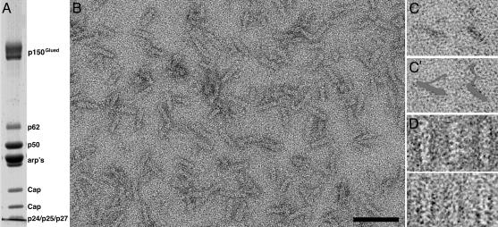
Characterization of Purified Dynactin Complex. SDS/PAGE analysis (Fig. 1A) showed that all known components of the complex were present and in expected ratios. The functionality of dynactin in terms of its ability to mediate dynein-dependent transport was confirmed by microtubule binding and gliding assays (unpublished data).
Fig. 1.
Characterization of purified dynactin complex. (A) SDS/PAGE (10% acrylamide gel) showing all components of purified dynactin complex are present. p50, dynamitin. The estimated ratio of the various components was 2:1:4:10:2 for p150Glued:p62:p50:arp:CaP. (B) Electron micrographs showing a field of negatively stained dynactin complexes. The distinctive rod or wedge shape of the complex, with a length of ≈35 nm, can be clearly discerned. (C) Positively stained images of the complex show the flexible shoulder and sidearm structure projecting from the backbone most clearly. (C′) Gray overlay of dynactin in C. (D) Gallery of selected aligned individual dynactin particles. Structural features such as the subunit backbone and gap between backbone strands can be seen. (Scale bar, 50 nm.)
Observation by transmission electron microscopy revealed dynactin to be a rod-shaped complex (Fig. 1 B–D). The shoulder/sidearm structure, which could be seen in positively stained samples (Fig. 1C), projects from the side of the filament backbone and appears highly extended and flexible. Samples previously frozen for storage showed excessive aggregation; therefore, only freshly purified dynactin was used. The overall shape and dimensions of the dynactin complexes were comparable to those observed elsewhere (10). Indications of substructure of the dynactin backbone could already be seen in many complexes (Fig. 1D).
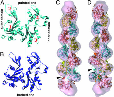
Alignment and Assessment of 2D Structure from Class Averages. It is known that Arp1 has a high sequence identity (54%) with actin (9) and predicted structural similarity (Fig. 4 A and B). The structure we observe in our class averages is consistent with observations that Arp1 is capable of forming filaments like actin (12). Visual assessment of backbone details for each class average strongly suggested polar structure. Subunit shape and inner and outer domains could be distinguished in many class averages (Fig. 2B, arrows). Based on structural similarity of the Arp1 subunit to G-actin and of the backbone seen in class averages to F-actin, we adopt actin terminology (defined in Fig. 4 A and B) to describe the structure of the Arp1 subunit and the backbone.
Fig. 4.
Modeling the structure of the dynactin backbone. (A) Tertiary structure predicted for Arp1 from sequence information (9) shows its close similarity to cytoskeletal actin (30) (PDB ID code 1HLU) in B. We adopt actin-related terminology to describe Arp1 structure, with inner and outer domains and four subdomains indicated. (C) Model 10-subunit Arp1 filament (see text for details) fitted into the dynactin electron-density map (contoured to the expected mass of the Arp) by using o (28). Goodness-of-fit indicates helicity is similar to that of F-actin. Extra mass in which it was not possible to fit additional Arp subunits can be seen at either end of the filament. (D) View 180° rotated about the long axis of the complex with respect to C. Subdomain 2 protrudes from the reconstructed density (arrowhead).
Fig. 2.
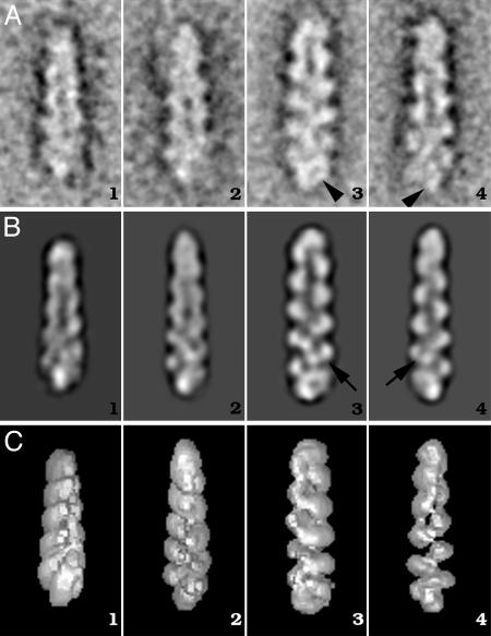
Class-averages and 2D projections of dynactin. (A) A selection of representative class-averages obtained after iterative multireference alignment. The polarity of the filaments is indicated by the orientation of the subunits within each class. The orientation is with the pointed end (F-actin terminology) at the top of the images. Arrowheads indicate halo and spike features at the end of the complex. (B) Two-dimensional reprojections of the 3D along Euler angles assigned to classes in A. A1–C1, tilted away from the viewer by 20° round the short axis; A2–C2, tilted 15° toward viewer; A3–C3 and A4–C4, side views rotated round the long axis by 150° with respect to each other. Note that the 2D reprojections of the 3D are comparable to their input class averages. The inner and outer domains of Arp1 backbone subunits are clearly visible (arrows). (C) Surface-rendered views of 3D reconstruction. Extra mass not clearly attributable to the Arp1 backbone structure is visible at the filament “barbed end”; this is particularly clear in the surface representations and gives rise to a distinctly non-F-actin-like appearance.
Backbone detail was used to orient classes with what was considered the pointed end at the top of the box. Statistical analysis of the fit of each normalized image in the data set to its normalized references class average was carried out, with the reference oriented as in Fig. 2 (up) and rotated 180° in-plane with respect to those in Fig. 2 (down). Images consistently showed a clear preference in alignment to one orientation over the other, with correlation coefficients of on average 0.554 ± 0.050 and 0.387 ± 0.049 for “correct” and “incorrect” orientations. This result demonstrates that the backbone is a polar structure and that the alignment procedure had no problem distinguishing between particles of different polarity. Class averages contained between 15 and 28 images. Direct measurement of the length of the complex in 80 aligned class averages (examples are given in Fig. 2 A) gave values of 34.8 ± 1.7 nm. The backbone of the complex is made up of 10 globular subunits forming a periodic structure with a maximal diameter of 9.7 ± 0.6 nm. The subunit axial rise of 2.75 ± 0.1 nm is comparable to actin filaments. In addition to the periodic structure of the Arp1 backbone, other mass is clearly visible at the bottom (barbed) end of the complex. This mass gives it a halo or spike-like appearance (Fig. 2 A3 and A4, respectively).
Euler-Angle Assignment and 3D Reconstruction. Our initial 3D reconstruction of the dynactin complex indicated that the views were limited to those around the long axis. This is due to the fact that the particle is a rod and therefore lies, naturally, on its long axis on the carbon support film. We also found that the backbone had a preferential orientation around its long axis, possibly due to the large shoulder/sidearm component projecting from its surface. A reconstruction by angular reconstitution methods without a starting anchor-set was not possible from this data set. The common-line theorem used in this method generally relies on there being at least three views of the molecule rotated around three distinct common tilt axes (29). Our direct measurements, from class averages (see above), show a high degree of similarity of the backbone to F-actin structure. To produce a 3D reconstruction from our data set, we therefore had a potential model, an Arp1 filament, that we could use as an anchor-set for an initial round of Euler-angle assignment. For the very first round of Euler-angle assignment, we built a low-resolution, 10-subunit Arp1 model (3-nm resolution) with F-actin helical parameters. Two-dimensional reprojections of the model were used as an anchor-set. All subsequent refinement steps were carried out by using only anchor-sets generated from data. There was a good representation of orientations (every 10°) over 200° around the long axis. To attempt to obtain more views and a more complete 3D structure, a separate tilted data set (<20% of total data set) was included in the final data set. Inclusion of these data (which included particles tilted around the short axis, β, 77–110°) improved the range of orientations around the long axis by a further 15°. Only data where structure in 2D reprojections from the 3D closely matched that of the input class averages was allowed to contribute to the final 3D. The resolution of the final map was ≈3 nm as determined by Fourier shell correlation (0.5 correlation value). All maps were low-passfiltered to this value before display here.
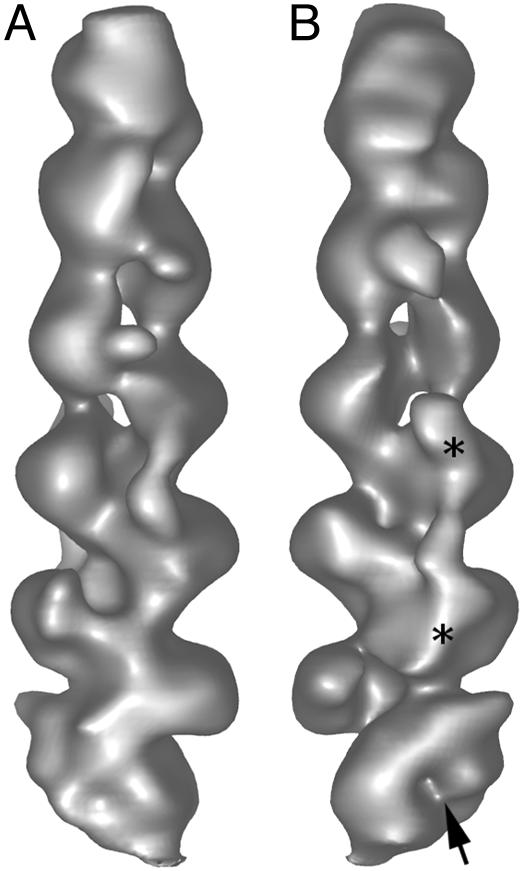
The 3D Structure of Dynactin and Fitting of Crystallographic Data and Models. In surface-rendered views (Figs. 2C and 3), the helical nature of the backbone subunits of the complex is clear. In addition to the periodic “zig-zag” structure of the Arp1 backbone, the extra mass contributing a halo or a spike of density is clearly visible, with a cleft in the density at the center of the halo (Fig. 3, arrow). This mass gives the complex a distinctly non-Factin-like appearance (see Fig. 2 A3 and A4, respectively). Views tilted away from the viewer (Fig. 2 B1 and C1) show that this central mass is elongated and crosses the barbed end of the filament.
Fig. 3.
Surface-rendered views of the 3D reconstruction of the dynactin complex. A and B are rotated 180° to each other about the long axis of the complex. The barbed end of the complex (bottom) appears distinctly different in different views, showing a non-actin-like structure with a clear cleft, indicated by an arrow. A discontinues strand of density is seen running at least part of the way along the dynactin backbone (e.g., between asterisks in B).
There are 10 strong, helically arranged, globular features in the backbone of our reconstruction of the dynactin complex. A 10-subunit Arp1 filament model with F-actin helical parameters fits well into our 3D reconstruction (Fig. 4 C and D). The goodness-of-fit strongly suggests that the helicity of the Arp1 filament is comparable to that of F-actin.
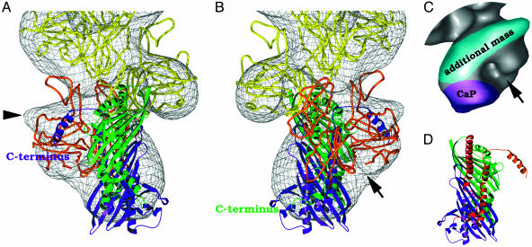
The fitting of the Arp backbone highlights the presence of additional non-helically arranged mass (i.e., not contributed by the backbone) at the barbed end. Additional Arp subunits did not fit well into this extra mass, which is most likely attributable to CaP (≈69 kDa), the only large globular protein thought to bind to at this end of the complex. A preliminary fitting of the elongated CapZ crystal structure (27) (Fig. 5 A and B) into this elongated mass was carried out by eye avoiding major steric clashes with the Arp subunits in the backbone. By this method, a good fit was obtained to the density and there was close agreement with the appearance of the distinctive “spike” or “halo” observed at the barbed end in original class average views when the fitted map was rotated to comparable orientations. The relative contributions of Arp1 and CaP to the distinctive “halo” structure of the barbed end begin to become clear (Fig. 5C). The gap between the ultimate Arp subunit and CaP gives rise to the cleft seen in the barbed end density. There is an additional shield-like mass in the region of the barbed end located across the outer face of the ultimate Arp subunit and projecting outward from the dynactin backbone (see Fig. 5C) that could not be accounted for by CaP density.
Fig. 5.
Docking of the crystal structure of CapZ (α-subunit in green, and β-subunit in purple) into the dynactin reconstruction. The bottom Arp (Arp1-1) is colored orange to distinguish it from its neighbor. Views rotated 180° around the long axis from each other (A and B). In our model the CaP mass lies over subdomain 3 of the two terminal Arp subunits. Additional density projecting out from the ultimate Arp is labeled (arrowhead in A). (C) Relative contributions of components to barbed end structure from Arp1, CaP (magenta), and an additional extra mass associated with the outer surface of Arp1-1 (highlighted in cyan). The 3D image is oriented as in B. A distinct cleft is observed at the bottom of the structure (arrow in B and C). (D) CapZ structure, oriented as in B, highlighting the long α-helices running along the underside of the β-sheets and the C-terminal portions of each subunit proposed to interact with the Arp1 backbone (27). Red, binding region of α-subunit; orange, binding region of β-subunit.
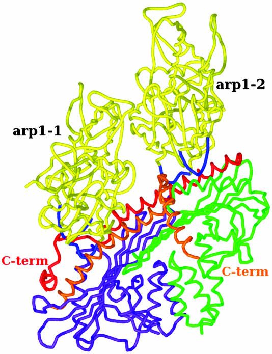
In our fitted model (Fig. 6), CaP lies across the central axis of the Arp1 backbone with each subunit located in an equivalent position over subdomain 3 of each of the ultimate two Arp subunits at the barbed end of the complex. The closest approaches to Arp are via long α-helices running along the underside of the β-sheets (these helices are shown in Fig. 5D). Additional mass not contributed by the backbone Arp subunits is also observed at the pointed end. This must be contributed by pointed end complex proteins (see Discussion for more detail).
Fig. 6.
Model of CaP binding to the barbed end of the Arp backbone (cartoon representation). Shown is a side-view of the bottom two Arp1 subunits at the barbed end of the dynactin reconstruction with the docked CapZ structure illustrating close approach of the long α-helices in α- and β-subunits (red and orange, respectively) to loops (blue) in subdomain 3 of the ultimate two Arps at the barbed end of the complex. The C-terminal portions of each subunit are also in positions where they could potentially interact with subdomain 3 of each Arp, if they were to change conformation as proposed by Yamashita et al. (27).
Discussion
The Dynactin Backbone. Dynactin is the essential component in the recognition and binding of the dynein molecular motor to its cargo. From direct measurements and fitting of models we have found that the dynactin backbone is, like F-actin, a polar structure where each subunit barbed end binds at the pointed end of the subunit lying directly above it in the backbone. This finding is consistent with previous observations (12) and with the ability of both types of filaments to bind spectrin. Spectrin is important in linking dynactin complex to the cargo (3). Spectrins bind to F-actin and Arp1 filaments via a doublet CH (calponin homology) domain (3, 31). Docking of crystallographic structures into 3D reconstructions of actin filaments decorated with CH domains from a variety of proteins (e.g., refs. 31–33) shows that spectrin makes contact with multiple actins/Arps in the filament backbone. Thus, for spectrin to perform its function in both F-actin and Arp1, the filament geometry must be preserved. A further similarity with F-actin is the under-representation of subdomain 2 of Arp1 in our reconstruction (Fig. 4 C and D), a phenomenon commonly observed in F-actin reconstructions (34). In actin this under-representation is attributed to the highly flexible nature of subdomain 2, and Arp1 appears to share this important characteristic. Subdomain 2 is intimately involved in forming subunit–subunit contacts along the long pitch helix of F-actin and possibly in transmitting cooperative conformational changes along filaments (35).
The PEC. The best-characterized component of the PEC is Arp11. Arp11 is thought to bind at the pointed end of the dynactin complex in a manner similar to Arp1, because residues involved in backbone formation are conserved at its barbed end. The tenth Arp subunit at the pointed end of the backbone of our structure is therefore likely to be the Arp11 subunit. Residues at the pointed end of Arp11 are not conserved with respect to other Arps, indicating that it performs some other function. This function is likely to be interaction with other PEC proteins, most likely with p62, which is thought to interact with both Arp1 and Arp11 (36) and probably accounts for most of the additional mass at the PEC in our reconstruction. We do not observe sufficient mass to account for the additional small proteins (p25 and p27) reportedly located at this end of the complex. This lack could be due to that fact that there is certain flexibility in the pointed end complex or that some of the extra mass is highly elongated or penetrated by stain and therefore not well resolved in our reconstruction.
The Barbed End. In our fit, CaP lies across the barbed end of the dynactin backbone with equivalent positions on each subunit closely approaching equivalent positions on the two barbed-end Arp1 subunits (Fig. 6). The potential for interaction with two Arp subunits is consistent with the fact that CaP binds to filamentous actin (or Arp1) but does not bind to monomers (37). The closest approach of CaP to Arp subunits is via the long α-helices running along the underside of the β-sheets of each subunit. These helices, and the C-terminal residues crucial for binding of the CaP subunits to actin/Arp, have been proposed as likely interaction points with the actin/Arp1 backbone (27, 37, 38). Yamashita et al. (27) suggested that C-terminal residues may change conformation to bind to Arp1. The closest approaches of CaP to Arp1 are to subdomain 3 of the two barbed-end Arp1 subunits, around residues associated with the longitudinal subunit–subunit interface of the Arp1 backbone. In our model, equivalent positions on CaP interact with equivalent positions on each of the two barbed-end Arp1 subunits. CaP possesses a twofold symmetrical architecture (residues crucial for maintaining architecture are conserved between the two subunits), which would be advantageous to this type of interaction (27). The CaP, positioned to directly block subunit–subunit interaction sites, would be optimally placed to perform its proposed role as a stabilizer (37, 39) of the filament backbone. It has been speculated that CaP might bind to the barbed end in a manner similar to gelsolin. However, the cleft between subdomains 1 and 3, to which gelsolin binds (PDB ID code 1C0F) (40), does not appear to be directly obstructed in our fitted map (Fig. 6B). A distinct mode of binding from that of gelsolin is therefore indicated. The mode of CaP binding has broader significance because it is also a key component in the organization of the Z-lines in muscle.
The Shoulder/Sidearm Complex. What we have described so far accounts for ≈60% of the mass of the dynactin complex; what of the rest? This is contained in the shoulder/sidearm complex. We do observe some mass located over, and projecting out from, the outer surface of the ultimate Arp at the barbed end (Fig. 5C). This mass is most likely contributed by the attachment point of the p150Glued/dynamitin “shoulder complex” thought to bind to the Arp1 backbone in this region (11). There is insufficient mass to account for the whole of p150Glued (2 × 150 kDa), dynamitin (4 × 50 kDa), and smaller globular proteins (2 × 24 kDa). In the case of the p150Glued, the most likely reason for this is that it is highly elongated, being made up of a large proportion of α-helical coiled-coil with it globular component placed at the end furthest from the Arp1 backbone (8). It is also very flexible, based on our own and previous observations (Fig. 1C) (11). These two factors mean that its structure will not be clearly observed in class averages. The issue with the dynamitin (shoulder complex) can be explained in the same manner because sequence prediction revealed a high potential for forming elongated α-helical coiled-coil (41) rather than a compact globular structure. It has been suggested that the dynamitin may lie along the backbone in a manner similar to tropomyosin on actin filaments; this is supported by “dotblot” comparison of dynamitin and tropomyosin sequence. This comparison shows that dynamitin has periodically arranged repeats very similar in spacing to those of tropomyosin that are regularly spaced at intervals of an integral number of actins (P. Bennett, personal communication). There would appear to be a discontinuous strand of density running along the backbone in our reconstruction (see Fig. 3) that may be attributed to the presence of dynamitin.
In conclusion, we have visualized the detailed structure of the dynactin complex and the way in which several of its key components fit together to perform their functions. The backbone closely resembles that of F-actin, and the capping protein appears to be bound in a unique way distinct from that of gelsolin but blocking subunit–subunit interaction sites. Fig. 7 shows a model of how the dynactin complex might be arranged based on our results and incorporating those of others (10, 11). One intriguing question that we would like to answer is whether dynamitin really does lie along the Arp1 backbone in a manner similar to tropomyosin in muscle filaments. Further biochemical characterization of the interactions between PEC proteins and their crystallization will aid us in further determination of the detailed structure of the PEC.
Fig. 7.
Model of dynactin complex based on a synthesis of our results and antibody mapping (10). P50, dynamitin. See text for more detail.
Acknowledgments
We thank Drs. Pauline Bennett, Ed Morris, Bruno Klaholz, and Elena Orlova for helpful comments during the course of this work and Drs. John Squire and Dieter Weiss for their continuous support. This work was supported, in part, by the Medical Research Council, British Council, the Deutscher Akademischer Austauschdienst, Deutsche Forschungsgemeinschaft Grant WE 790/18-1, and Wellcome Trust Grant 045449.
Author contributions: W.S. designed research; J.L.H., C.P., S.A.K., and W.S. performed research; S.A.K. contributed new reagents/analytic tools; J.L.H. and C.P. analyzed data; and J.L.H. and W.S. wrote the paper.
This paper was submitted directly (Track II) to the PNAS office.
Abbreviations: CaP, capping protein; PEC, pointed-end complex.
References
- 1.Gill, S. R., Schroer, T. A., Szilak, I., Steuer, E. R., Sheetz, M. P. & Cleveland, D. W. (1991) J. Cell Biol. 115, 1639-1650. [DOI] [PMC free article] [PubMed] [Google Scholar]
- 2.Steffen, W., Karki, S., Vaughan, K. T., Vallee, R. B., Holzbaur, E. L., Weiss, D. G. & Kuznetsov, S. A. (1997) Mol. Biol. Cell. 8, 2077-2088. [DOI] [PMC free article] [PubMed] [Google Scholar]
- 3.Muresan, V., Stankewich, M. C., Steffen, W., Morrow, J. S., Holzbaur, E. L. & Schnapp, B. J. (2001) Mol. Cell 7, 173-183. [DOI] [PubMed] [Google Scholar]
- 4.King, S. J. & Schroer, T. A. (2000) Nat. Cell Biol. 2, 20-24. [DOI] [PubMed] [Google Scholar]
- 5.Howell, B. J., McEwen, B. F., Canman, J. C., Hoffman, D. B., Farrar, E. M., Rieder, C. L. & Salmon, E. D. (2001) J. Cell Biol. 155, 1159-1172. [DOI] [PMC free article] [PubMed] [Google Scholar]
- 6.Lee, W. L., Oberle, J. R. & Cooper, J. A. (2003) J. Cell Biol. 160, 355-364. [DOI] [PMC free article] [PubMed] [Google Scholar]
- 7.Merdes, A., Ramyar, K., Vechio, J. D. & Cleveland, D. W. (1996) Cell 87, 447-458. [DOI] [PubMed] [Google Scholar]
- 8.Waterman-Storer, C. M., Karki, S. & Holzbaur, E. L. (1995) Proc. Natl. Acad. Sci. USA 92, 1634-1638. [DOI] [PMC free article] [PubMed] [Google Scholar]
- 9.Lees-Miller, J. P., Helfman, D. M. & Schroer, T. A. (1992) Nature 359, 244-246. [DOI] [PubMed] [Google Scholar]
- 10.Schafer, D. A., Gill, S. R., Cooper, J. A., Heuser, J. E. & Schroer, T. A. (1994) J. Cell Biol. 126, 403-412. [DOI] [PMC free article] [PubMed] [Google Scholar]
- 11.Eckley, D. M., Gill, S. R., Melkonian, K. A., Bingham, J. B., Goodson, H. V., Heuser, J. E. & Schroer, T. A. (1999) J. Cell Biol. 147, 307-320. [DOI] [PMC free article] [PubMed] [Google Scholar]
- 12.Bingham, J. B. & Schroer, T. A. (1999) Curr. Biol. 9, 223-226. [DOI] [PubMed] [Google Scholar]
- 13.Casella, J. F., Craig, S. W., Maack, D. J. & Brown, A. E. (1987) J. Cell Biol. 105, 371-379. [DOI] [PMC free article] [PubMed] [Google Scholar]
- 14.DiNubile, M. J., Cassimeris, L., Joyce, M. & Zigmond, S. H. (1995) Mol. Biol. Cell. 6, 1659-1671. [DOI] [PMC free article] [PubMed] [Google Scholar]
- 15.Karki, S. & Holzbaur, E. L. (1995) J. Biol. Chem. 270, 28806-28811. [DOI] [PubMed] [Google Scholar]
- 16.Vaughan, K. T. & Vallee, R. B. (1995) J. Cell Biol. 131, 1507-1516. [DOI] [PMC free article] [PubMed] [Google Scholar]
- 17.Garces, J. A., Clark, I. B., Meyer, D. I. & Vallee, R. B. (1999) Curr. Biol. 9, 1497-1500. [DOI] [PubMed] [Google Scholar]
- 18.Bingham, J. B., King, S. J. & Schroer, T. A. (1998) Methods Enzymol. 298, 171-184. [DOI] [PubMed] [Google Scholar]
- 19.Vale, R. D., Reese, T. S. & Sheetz, M. P. (1985) Cell 42, 39-50. [DOI] [PMC free article] [PubMed] [Google Scholar]
- 20.Hodgkinson, J. L. & Steffen, W. (2001) Methods Mol. Biol. 161, 133-139. [DOI] [PubMed] [Google Scholar]
- 21.van Heel, M., Harauz, G., Orlova, E. V., Schmidt, R. & Schatz, M. (1996) J. Struct. Biol. 116, 17-24. [DOI] [PubMed] [Google Scholar]
- 22.van Heel, M., Gowen, B., Matadeen, R., Orlova, E. V., Finn, R., Pape, T., Cohen, D., Stark, H., Schmidt, R., Schatz, M. & Patwardhan, A. (2000) Q. Rev. Biophys. 33, 307-369. [DOI] [PubMed] [Google Scholar]
- 23.Paul, D., Patwardham, A., Squire, J. M. & Morris, E. P. (2004) J. Struct. Biol. 148, 236-250. [DOI] [PubMed] [Google Scholar]
- 24.Peitsch, M. C. (1995) Bio/Technology 13, 658-660. [Google Scholar]
- 25.Schwede, T., Diemand, A., Guex, N. & Peitsch, M. C. (2000) Res. Microbiol. 151, 107-112. [DOI] [PubMed] [Google Scholar]
- 26.Holmes, K. C., Angert, I., Kull, F. J., Jahn, W. & Schroder, R. R. (2003) Nature 425, 423-427. [DOI] [PubMed] [Google Scholar]
- 27.Yamashita, A., Maeda, K. & Maeda, Y. (2003) EMBO J. 22, 1529-1538. [DOI] [PMC free article] [PubMed] [Google Scholar]
- 28.Jones, T. A., Zou, J. Y., Cowan, S. W. & Kjeldgaard (1991) Acta Crystallogr. A 47, 110-119. [DOI] [PubMed] [Google Scholar]
- 29.van Heel, M. (1987) Ultramicroscopy 20, 111-124. [DOI] [PubMed] [Google Scholar]
- 30.Chik, J. K., Lindberg, U. & Schutt, C. E. (1996) J. Mol. Biol. 263, 607-623. [DOI] [PubMed] [Google Scholar]
- 31.Sutherland-Smith, A. J., Moores, C. A., Norwood, F. L., Hatch, V., Craig, R., Kendrick-Jones, J. & Lehman, W. (2003) J. Mol. Biol. 329, 15-33. [DOI] [PubMed] [Google Scholar]
- 32.Bramham, J., Hodgkinson, J. L., Smith, B. O., Uhrin, D., Barlow, P. N. & Winder, S. J. (2002) Structure (London) 10, 249-258. [DOI] [PubMed] [Google Scholar]
- 33.Hodgkinson, J. L., el-Mezgueldi, M., Craig, R., Vibert, P., Marston, S. B. & Lehman, W. (1997) J. Mol. Biol. 273, 150-159. [DOI] [PubMed] [Google Scholar]
- 34.Orlova, A. & Egelman, E. H. (1993) J. Mol. Biol. 232, 334-341. [DOI] [PubMed] [Google Scholar]
- 35.Hodgkinson, J. L. (2001) J. Muscle Res. Cell Motil. 20, 115-130. [DOI] [PubMed] [Google Scholar]
- 36.Eckley, D. M. & Schroer, T. A. (2003) Mol. Biol. Cell 14, 2645-2654. [DOI] [PMC free article] [PubMed] [Google Scholar]
- 37.Hug, C., Miller, T. M., Torres, M. A., Casella, J. F. & Cooper, J. A. (1992) J. Cell Biol. 116, 923-931. [DOI] [PMC free article] [PubMed] [Google Scholar]
- 38.Kwiateck, O., Papa, I., Lebart, M. C., Benyamin, Y. & Roustan, C. (2000) Comp. Biochem. Physiol. B 127, 551-562. [DOI] [PubMed] [Google Scholar]
- 39.Littlefield, R. & Fowler, V. M. (1998)) Annu. Rev. Cell Dev. Biol. 14, 487-525. [DOI] [PubMed] [Google Scholar]
- 40.McLaughlin, P. J., Gooch, J. T., Mannherz, H. G. & Weeds, A. G. (1993) Nature 364, 685-692. [DOI] [PubMed] [Google Scholar]
- 41.Echeverri, C. J., Paschal, B. M., Vaughan, K. T. & Vallee, R. B. (1996) J. Cell Biol. 132, 617-633. [DOI] [PMC free article] [PubMed] [Google Scholar]


