Abstract
Cell disruption plays a vital role in detection of intracellular components which contain information about genetic and disease characteristics. In this paper, we demonstrate a novel microfluidic platform based on an on-chip micropump for mechanical cell disruption and sample transport. A 50 μl cell sample can be effectively lysed through on-chip multi-disruption in 36 s without introducing any chemical agent and suffering from clogging by cellular debris. After 30 cycles of circulating disruption, 80.6% and 90.5% cell disruption rates were achieved for the HEK293 cell sample and human natural killer cell sample, respectively. Profiting from the feature of pump-on-chip, the highly integrated platform enables more convenient and cost-effective cell disruption for the analysis of intracellular components.
I. INTRODUCTION
Intracellular components containing information about genetic and disease characteristics are pivotal substances to clinical diagnostics, and these desired components are isolated from the surrounding medium by an impermeable cell membrane.1,2 Cell disruption plays a vital role in obtaining intracellular components whose quality will directly influence the subsequent analysis. Cell disruption, also called cell lysis, is a process to break apart cell membranes to access intracellular substances such as proteins, nucleic acids, and organelles for subsequent analysis.3,4 A variety of cell disruption approaches have been developed, including chemical,5–7 mechanical,8–10 electrical,11–14 optical,15,16 acoustic,17,18 and thermal19,20 methods. The most well-established lysis approach is chemical lysis, which is simple to implement and needs only mixing for activation.21 However, the chemical reagent in lysis buffer may result in protein denaturation,22 and in some cases, additional separation steps should be needed for removing the reagent, which increases the complexity for system integration.23,24 Other approaches conventionally require bulky or specialized instrumentation to stimulate and disrupt the cells, which makes it hard to be integrated with subsequent analysis devices.25 Now, the development of microfluidics has made it possible for a cell lysis device to be integrated in a chip, and a microfluidic chip could also supply a relatively airtight environment, which prevents cells against external pollution.26,27 The mechanical disruption method is relatively easy to be integrated in a microfluidic chip because it is done by tearing or puncturing cell membranes using mechanical forces, including friction forces, shear stress, and compressive stress, which can be induced by structures within a microfluidic chip. The mechanical disruption method based on microfluidics is more effective, facile, and simpler than the other methods, without the requirement for chemical agents or bulky instrumentation, and causes no harm to intracellular components.
Di Carlo et al. presented a mechanical lysis device with ultra-sharp silicon nano-blade arrays for HL-60 and whole blood cell disruption. When cells passed through the sharp blade arrays within a microfluidic channel, friction forces and shearing stresses would easily penetrate the cell membrane.28 Based on the same principle, Yun et al. demonstrated a handheld microfluidic chip with silicon nanobarbs to disrupt EL4 mouse T-lymphoma cells.29 Kim et al. presented a microfluidic device with patterned nanowire-integrated micropost arrays for facile HaCaT and HeLa cell disruption.30 When cells passed through the micropost arrays, they would be ruptured by a strong physical interaction with the nanowire bundles.30 However, in these previous studies, they are facing the problems of clogging by cellular debris and flow instability at the nanostructure arrays,30,31 and the fabrication of nanostructures within microchannels required a strict process control.28,29 Moreover, all the reported microfluidic disruption platforms required external fluid-driving sources, which obstruct the entire system's miniaturization.32,33
In this paper, we introduce a novel mechanical cell disruption microfluidic platform based on an on-chip micropump, and the platform overcomes the problems of clogging and external fluid-driving source requirement. The on-chip micropump serves not only as a fluid-driving source but also as disruption cells in a mechanical way. We have experimentally demonstrated that the microfluidic platform could efficiently disrupt the HEK 293 cell (human embryonic kidney 293 cell) and white blood cell sample. The cell disruption microfluidic chip consists of two poly(dimethylsiloxane) (PDMS) layers and a polymethyl methacrylate (PMMA) substrate, which is easy for fabrication and widely used in microfluidics, thus easily integrated with downstream modules for on-chip analysis.
II. THE CELL DISRUPTION CHIP
A. Design
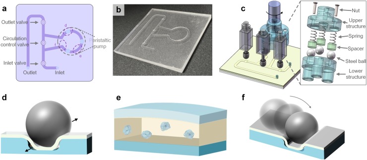
Fig. 1 shows a schematic of the pump-on-chip cell disruption platform, and it consists of a cell disruption microfluidic chip and a driving setup. The chip is composed of an on-chip micropump for cell disruption and sample transport, three valves, channels, an inlet, and an outlet (Fig. 1(a)). The driving setup includes a rotary motor for driving the on-chip micropump, three electromagnets for valve control, and a home-made control system (Fig. 1(c)). On the motor head are evenly mounted three steel balls, which are set in contact with the PDMS membrane-covered annular channel to disrupt cells and pump fluid. The driving device of the on-chip micropump consists of a lower structure, steel ball, spacer, spring, nut, and upper structure. To control the valves, three electromagnets are set above the PDMS membrane at designated points. Working as a mechanical contact switch, the electromagnet deforms the PDMS membrane to close the valve when power is on. A portable control system based on STM32 controls the motor and electromagnets to accomplish the disruption procedure, and the rotary motor rotation speed is accurately controlled using pulse width modulation (PWM). All the cell disruption processes, including sample loading, cell disruption, and cell lysate collection, are automatically controlled by the portable control system. The chip consists of three structured layers, starting from the bottom, including a bottom PMMA substrate layer, a PDMS channel layer, and a top PDMS membrane layer. Fig. 1(b) shows a photograph of a fabricated cell disruption microfluidic chip.
FIG. 1.
The pump-on-chip cell disruption microfluidic chip. (a) Schematic of the chip, (b) photograph of the fabricated cell disruption microfluidic chip, and (c) schematic of the platform including the on-chip micropump, electromagnets, and microfluidic chip. This platform performs effective mechanical cell disruption with several reasons: (d) cells in the sample leaking through the gap between the channel corners and the PDMS membrane will be pulverized by the steel balls, (e) the compressive stress makes cells deform and bulges form on the cell membrane followed by cell bursting, and (f) some cells will be crushed down by the steel balls dropping down from the step.
As the most essential component which contributes to cell disruption, the on-chip micropump is composed of an annular channel covered by a 120 μm thick PDMS membrane which is pressed by three steel balls driven by a direct-current motor. The width, depth, and outer diameter of the annular channel were 2 mm, 200 μm, and 18 mm, respectively. The flexible PDMS membrane peristaltically deforms by the circular movement of the three balls with diameters as large as 6 mm, and the peristaltic deformation of the membrane disrupts cells and drives the fluid flow in the channel.34,35 The flow rate of the on-chip micropump can be adjusted by the rotation speed of the motor. This platform performs effective mechanical cell disruption with several reasons. First, when the peristaltic deformation of the PDMS membrane drives the liquid sample flow, a certain amount of sample will leak through the gap between the channel corners and the PDMS membrane. The cells in the sample leaking through the gap will be pulverized by the steel balls. Second, a compressive stress is directly applied to cells through the flexible PDMS membrane which deforms by the circular movement of the three balls, and this makes cells deform and bulges form on the cell membrane followed by cell bursting.9 Last, the on-chip micropump channel is not fully annular; therefore, the steel balls will drop down from the step, which will crush down some cells. This on-chip pump-based platform enables more convenient and cost-effective cell disruption for the analysis of intracellular components, making it suitable as a sample pretreatment module for point-of-care testing, and this microfluidic module can be integrated with other modules, realizing multiple functionalities on a single chip to form a total analysis system.
Cell disruption starts from sample loading, in which a specific volume of sample is suctioned from the inlet with the circulation control valve closed. During sample loading, the sample is transported to the micropump region, where the cells will be disrupted by the compressive stress and pulverized by the three steel balls. After sample loading, the chip works repeatedly in the multi-disruption step to achieve more disruptions and enhance the cell disruption rate until the disruption performance is satisfactory. During this step, both the inlet and outlet valves are closed, and the circulation control valve is opened. After cell disruption, the cell lysate is extracted via the outlet for subsequent analysis, by introducing the sample with the circulation control valve closed.
B. Fabrication
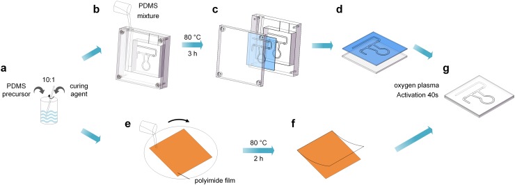
We fabricated the pump-on-chip cell disruption microfluidic chip as shown in Fig. 2. A polymethyl methacrylate (PMMA) mold and a square PMMA substrate are fabricated by using a computer numerically controlled (CNC) machine. The PDMS precursor (Sylgard 184 elastomer, Dow Corning) is mixed with its curing agent at a ratio of 10:1 by weight (Fig. 2(a)). After stirring and degassing under 10 Pa vacuum for 10 min, the PDMS mixture is poured into the mold to form the channel layer (Fig. 2(b)). Then, the PDMS channel layer is baked at 80 °C for 3 h, peeled off from the mold (Fig. 2(c)), and assembled onto the square PMMA substrate (Fig. 2(d)). A 120 μm PDMS membrane is prepared by using a spin-coating PDMS mixture on a polyimide film (Fig. 2(e)) and then baking 2 h at 80 °C (Fig. 2(f)). The PDMS membrane is bonded to the assembled PMMA layer after oxygen plasma activation (50 Pa, 100 W) for 40 s (Fig. 2(g)). Access holes were punched through the top PDMS membrane at positions corresponding to the inlet and outlet. Finally, the channels were sterilized with 70% ethanol and rinsed thoroughly with phosphate-buffered saline buffer.
FIG. 2.
Schematic of the procedure for fabricating a pump-on-chip cell disruption microfluidic chip.
III. MATERIALS AND METHODS
A. Materials and measurements
Two cell types were used in this study. Both the cell lines, human embryonic kidney 293 (HEK293) cells and human natural killer (NK) cells, were cultured at 37 °C in a 5% (v/v) CO2 incubator and were maintained in Dulbecco's modified Eagle's medium (DMEM). All cells were cultured for 5 days prior to the experiment, and the cell concentration in the sample is about 3 × 10⁵ cells/μl. All experiments were performed in compliance with all relevant laws and institutional guidelines and were approved by Tsinghua University.
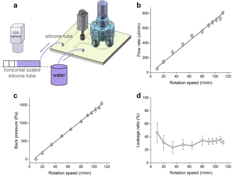
The on-chip micropump is characterized by a home-made setup as shown in Fig. 3(a). Essentially, the flow meniscus in a horizontal or a vertical scaled tube connected to the outlet tube of the chip is measured by using a CCD camera, and then the flow rate or the back pressure of the micropump is calculated, respectively.
FIG. 3.
Characteristics of the on-chip micropump. (a) Schematic of the setup for flow rate testing, (b) the relationship between the flow rate and rotation speed at zero back pressure, (c) the relationship between back pressure and rotation speed, and (d) the relationship between the leakage ratio and rotation speed at zero back pressure. Error bars in (b), (c), and (d) represent the standard deviations of 5 separate trials.
The total protein concentration in the sample supematant before and after disruption is determined by using a spectrophotometer (NanoPhotometer® P330, Implen GmbH, Germany), which is used to evaluate the disruption performance. The optical absorbance of intracellular proteins in 10 μl sample solutions is measured at a wavelength of λ = 280 nm to identify amino acids such as tryptophan, tyrosine, and cysteine. The absorbance of proteins may differ according to the relative concentrations of these three amino acids, and the absorbance values are automatically processed to obtain the total protein concentration in the sample.30 A Zeiss LSM 780 confocal laser scanning microscope with 10×, 20×, and 40× multi-immersion objective lens is used for sample observation and image recording.
B. Performance metrics
Cell disruption is the breaking apart of cell membranes to affect the release of the intracellular product, thus allowing subsequent analysis. There are direct and indirect methods to measure the cell disruption performance. Direct measures may be determined by observational methods such as counting using a microscope, while indirect methods involve monitoring the release of the specific product from cells, which locates intracellularly before disruption. In this study, we use the total protein concentration in the sample supematant to quantitatively analyze the cell disruption performance and use a confocal microscope for qualitative analysis. To evaluate the cell disruption performance and efficacy, the cell disruption rate is defined by3,36,37
| (1) |
where Protein sample is the protein concentration in the sample, Protein control is the protein concentration in the initial cell sample, and Protein total is the maximum possible protein concentration in the sample when all of the cells are disrupted. Herein, we measure the Protein total by completely disrupting the cells using an Avestin Emulsiflex C3 Homogenizer at 1600 psi.
IV. EXPERIMENTAL RESULTS
A. Characteristics of the on-chip micropump
Figure 3 shows the measurement results of the on-chip micropump characteristics with a steel ball pressing depth of 250 μm. The flow rate increases from ∼49 μl/min to ∼808 μl/min following the rising of the motor rotation speed from 10 r/min to 112 r/min at a linear relationship (Fig. 3(b)). As expected, the back pressure also followed an approximate linear relationship with the rotation speed, and a back pressure up to 1550 Pa is achieved at 112 r/min (Fig. 3(c)). The leakage ratio is approximately constant when the motor rotation speed is higher than 20 r/min (Fig. 3(d)), which is based on the micropump volume capacity, motor rotation speed, and flow rate.
B. Optimization of rotation speed and pressing depth
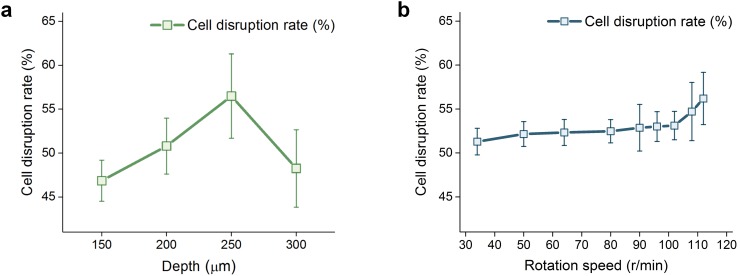
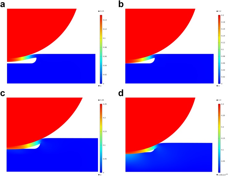
First, the influence of the pressing depth of the steel balls on the chip on cell disruption performance is evaluated by pumping the 50 μl sample with 4 different pressing depths from 150 μm to 300 μm with a motor rotation speed of 112 r/min. Fig. 4(a) shows the cell disruption rate with different pressing depths. The cell disruption rate first increases with the pressing depth, achieves the maximum 56.5% at 250 μm, and then turns to decrease. The channel state in the micropump area when pressed by steel balls with different pressing depths is simulated using the finite element analysis method based on the 2D contact model established with COMSOL. The simulation results with pressing depths of 150 μm, 200 μm, 250 μm, and 300 μm are shown in Figs. 5(a)–5(d), and the areas of the gap between the channel corners and the PDMS membrane are 53.27%, 29.36%, 17.37%, and 4.26% of the initial area, respectively, illustrating that the gap area decreases with the increase in the pressing depth. With a smaller gap between the bottom PDMS channel layer and the top PDMS membrane, a higher compressive stress is achieved, and cells leaking through the gap will be pulverized by the steel balls more thoroughly; however, if the gap is too small or even if there is no gap, there will be only few cells be disrupted. We further evaluate the effect of the motor rotation speed on cell disruption performance by pumping the 50 μl sample with 9 different rotation speeds from 34 r/min to 112 r/min and a pressing depth of 250 μm, and Fig. 4(b) shows the cell disruption rate with different rotation speeds. The cell disruption rate increases slowly with rotation speed and achieves 56.2% at 112 r/min since the compressive stress and friction forces will increase with rotation speed. In order to maximize the cell disruption rate, a pressing depth of 250 μm and a motor rotation speed of 112 r/min (flow rate corresponding to 808 μl/min) are selected in the subsequent experiments.
FIG. 4.
Cell disruption rates with different rotation speeds and pressing depths of the external motor. (a) Results for cell disruption with different pressing depths of the steel balls and (b) results for cell disruption with different motor rotation speeds. Error bars in (a) and (b) represent the standard deviations of 5 separate trials.
FIG. 5.
Simulation results of the channel state in the micropump area when pressed by steel balls with different pressing depths. (a)–(d) Simulation results with pressing depths of 150 μm, 200 μm, 250 μm, and 300 μm, respectively.
In order to estimate the contribution of flow speed on cell disruption, we tested the effect of cell disruption using a syringe pump to introduce the HEK293 cell sample into the microfluidic chip, comparing with the on-chip micropump, with a same flow rate of 808 μl/min. Fig. 6(a) shows a microscopic image of the initial HEK293 cell sample, and Figs. 6(b) and 6(c) show the microscopic images of collected samples after loading the sample through the microfluidic chip using a syringe pump (LongerPump® LSP02-1B, China) and the on-chip micropump, respectively. The cell disruption rate is 56.9% using the on-chip micropump, significantly higher than 4.7% using the syringe pump (Fig. 6(d)). This confirms that the cells are effectually disrupted under compression by the on-chip micropump in a mechanical way. This novel mechanical cell disruption platform allows rapid extraction of intracellular contents without introducing chemical agents or applying bulky instrumentation. In addition, this mechanical method causes no harm to intracellular contents and will not influence the subsequent extraction and analysis.
FIG. 6.
The effects of cell disruption using two different kinds of pumps. (a) Microscopic image of the initial HEK293 cell sample. (b) and (c) Microscopic images of collected samples after loading the sample through the microfluidic chip using a syringe pump and the on-chip micropump, respectively. (d) Cell disruption rate using the syringe pump and on-chip micropump. Scale bars in (a)–(c) represent 10 μm, and the error bar in (d) represents the standard deviations of 5 different trials.
C. Multi-disruption
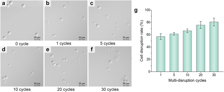
A pre-disruption is carried out by introducing the 50 μl cell sample, and then the circulating disruption step is repeated multiple times to implement on-chip multi-disruption for a better disruption effect. Herein, experiments with different numbers of repeating cycles of the circulating disruption step are conducted. Fig. 7 shows the HEK293 cells' cell disruption results with different numbers of repeating cycles of the circulating disruption step. The cells in the initial sample are intact (Fig. 7(a)). More disruption cycles cause breakdown of an increasing number of cells and the release of more intracellular components and increase the amount of cell debris from cracked and split cells in the sample solution (Figs. 7(b)–7(f)), thus resulting in a higher protein concentration. The cell disruption rate increases significantly with the repeating cycles of the circulating disruption step (Fig. 7(g)), indicating that this step is highly effective to improve the cell disruption performance. After 30 cycles of the circulating disruption step, the 80.6% cell disruption rate is achieved, and the cell disruption rate could be further enhanced by increasing the repeating cycles.
FIG. 7.
HEK293 cells' cell disruption results with different repeating cycles of the circulating disruption step. (a) Microscopic image of the initial HEK293 cell sample. (b)–(f) Microscopic images of collected samples with 1, 5, 10, 20, and 30 repeating cycles of the circulating disruption step. (g) Cell disruption rate versus repeating cycles. Scale bars in (a)–(f) represent 30 μm, and the error bar in (g) represents the standard deviations of 5 different trials.
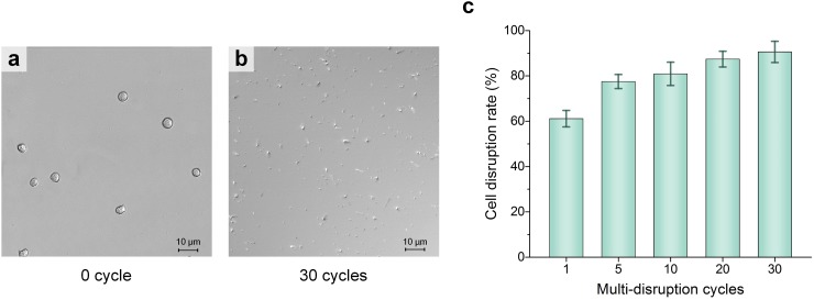
Following the same procedure as HEK293 cell disruption, the 50 μl human natural killer (NK) cell sample is disrupted using this pump-on-chip cell disruption platform, with the circulating disruption step being repeated 1–30 times. Figs. 8(a) and 8(b) show the microscopic images of the initial NK cell sample and collected sample with 30 repeating cycles of the circulating disruption step, respectively. Fig. 8(c) shows the cell disruption rate of NK cells versus repeating cycles, and a cell disruption rate of over 90.5% is achieved after 30 cycles of circulating disruption. Herein, the disruption process with 30 repeating cycles of the circulating disruption step only takes 36 s to disrupt the 50 μl cell sample, equivalent to a throughput of 83.3 μl/min.
FIG. 8.
NK cells' cell disruption results with different repeating cycles of the circulating disruption step. (a) Microscopic images of the initial NK cell sample. (b) Microscopic image of the collected sample with 30 repeating cycles of the circulating disruption step. (c) Cell disruption rate versus repeating cycles. Scale bars in (a) and (b) represent 10 μm, and the error bar in (c) represents the standard deviations of 5 different trials.
V. CONCLUSIONS
In this paper, a novel pump-on-chip cell disruption microfluidic platform was demonstrated for mechanical cell disruption. The platform features with an on-chip micropump for mechanical cell disruption and sample transport. Utilizing this platform, we enabled efficient extraction of intracellular components without the need for introducing chemical agents or applying bulky instrumentation, and the 50 μl cell sample could be effectively lysed by on-chip multi-disruption in 36 s. After 30 cycles of the circulating disruption step, 80.6% and 90.5% cell disruption rates were achieved for the HEK293 cell sample and human NK cell sample, respectively. We believe that this cell disruption method can be further enhanced for a multitude of cells, and the cell disruption rate could be further improved by increasing the repeating cycles of circulating disruption. Profiting from the feature of pump-on-chip, this highly integrated platform enables more convenient and cost-effective cell disruption for analysis of intracellular components, making it suitable as a sample pretreatment module for point-of-care testing.
ACKNOWLEDGMENTS
This work was supported by the National Instrumentation Program (Grant No. 2013YQ19046701), the NSFC (Grant No. 61376120), the National Key R&D Program (No. 2016YFC0900200), and the One-Thousand Young Talent Program of China. The authors acknowledge suggestions from Professor Hongwei Wang and Ph.D. student Chuya Niu.
References
- 1. El-Ali J., Sorger P. K., and Jensen K. F., Nature 442, 403 (2006). 10.1038/nature05063 [DOI] [PubMed] [Google Scholar]
- 2. Nan L., Jiang Z., and Wei X., Lab Chip 14, 1060 (2014). 10.1039/c3lc51133b [DOI] [PubMed] [Google Scholar]
- 3. Middelberg A. P. J., Biotechnol. Adv. 13, 491 (1995). 10.1016/0734-9750(95)02007-P [DOI] [PubMed] [Google Scholar]
- 4. Günerken E., D'Hondt E., Eppink M. H. M., Garcia-Gonzalez L., Elst K., and Wijffels R. H., Biotechnol. Adv. 33, 243 (2015). 10.1016/j.biotechadv.2015.01.008 [DOI] [PubMed] [Google Scholar]
- 5. Zheng H., Yin J., Gao Z., Huang H., Ji X., and Dou C., Appl. Biochem. Biotechnol. 164, 1215 (2011). 10.1007/s12010-011-9207-1 [DOI] [PubMed] [Google Scholar]
- 6. Hejazi M. A. and Wijffels R. H., Trends Biotechnol. 22, 189 (2004). 10.1016/j.tibtech.2004.02.009 [DOI] [PubMed] [Google Scholar]
- 7. Molina Grima E., Belarbi E. H., Acién Fernández F. G., Robles Medina A., and Chisti Y., Biotechnol. Adv. 20, 491 (2003). 10.1016/S0734-9750(02)00050-2 [DOI] [PubMed] [Google Scholar]
- 8. Balasubramanian R. K., Yen Doan T. T., and Obbard J. P., Chem. Eng. J. 215–216, 929 (2013). 10.1016/j.cej.2012.11.063 [DOI] [Google Scholar]
- 9. Kim Y. C., Kang J. H., Park S. J., Yoon E. S., and Park J. K., Sens. Actuators, B 128, 108 (2007). 10.1016/j.snb.2007.05.050 [DOI] [Google Scholar]
- 10. Grimi N., Dubois A., Marchal L., Jubeau S., Lebovka N. I., and Vorobiev E., Bioresour. Technol. 153, 254 (2014). 10.1016/j.biortech.2013.12.011 [DOI] [PubMed] [Google Scholar]
- 11. Bao N., Wang J., and Lu C., Electrophoresis 29(14), 2939 (2008) 10.1002/elps.200700856. [DOI] [PubMed] [Google Scholar]
- 12. Zhan Y., Martin V. A., Geahlen R. L., and Lu C., Lab Chip 10, 2046 (2010). 10.1039/c005152g [DOI] [PMC free article] [PubMed] [Google Scholar]
- 13. Geng T., Bao N., Sriranganathanw N., Li L., and Lu C., Anal. Chem. 84, 9632 (2012). 10.1021/ac3026064 [DOI] [PMC free article] [PubMed] [Google Scholar]
- 14. Zhan Y., Sun C., Cao Z., Bao N., Xing J., and Lu C., Anal. Chem. 84, 8102 (2012). 10.1021/ac302462s [DOI] [PubMed] [Google Scholar]
- 15. Vogel A., Noack J., Nahen K., Theisen D., Busch S., Parlitz U., Hammer D. X., Noojin G. D., Rockwell B. A., and Birngruber R., Appl. Phys. B: Lasers Opt. 68, 271 (1999). 10.1007/s003400050617 [DOI] [Google Scholar]
- 16. Rau K. R., Quinto-Su P. A., Hellman A. N., and Venugopalan V., Biophys. J. 91, 317 (2006). 10.1529/biophysj.105.079921 [DOI] [PMC free article] [PubMed] [Google Scholar]
- 17. Zhang H. and Jin W., J. Chromatogr. A 1104, 346 (2006). 10.1016/j.chroma.2005.11.083 [DOI] [PubMed] [Google Scholar]
- 18. Halim R., Harun R., Danquah M. K., and Webley P. A., Appl. Energy 91, 116 (2012). 10.1016/j.apenergy.2011.08.048 [DOI] [Google Scholar]
- 19. Lee C.-Y., Lee G.-B., Lin J.-L., Huang F.-C., and Liao C.-S., J. Micromech. Microeng. 15, 1215 (2005). 10.1088/0960-1317/15/6/011 [DOI] [Google Scholar]
- 20. Ke C., Kelleher A. M., Berney H., Sheehan M., and Mathewson A., Sens. Actuators, B 120, 538 (2007). 10.1016/j.snb.2006.03.019 [DOI] [Google Scholar]
- 21. Schilling E. A., Kamholz A. E., and Yager P., Anal. Chem. 74, 1798 (2002). 10.1021/ac015640e [DOI] [PubMed] [Google Scholar]
- 22. Gromov P., Celis J. E., Gromova I., Rank F., Timmermans-Wielenga V., and Moreira J. M. A., Mol. Oncol. 2, 368 (2008). 10.1016/j.molonc.2008.09.003 [DOI] [PMC free article] [PubMed] [Google Scholar]
- 23. Hong J. W., Studer V., Hang G., Anderson W. F., and Quake S. R., Nat. Biotechnol. 22, 435 (2004). 10.1038/nbt951 [DOI] [PubMed] [Google Scholar]
- 24. Huang B., Wu H., Bhaya D., Grossman A., Granier S., Kobilka B. K., and Zare R. N., Science 315, 81 (2007). 10.1126/science.1133992 [DOI] [PubMed] [Google Scholar]
- 25. Salonen A., Nikkilä J., Jalanka-Tuovinen J., Immonen O., Rajilić-Stojanović M., Kekkonen R. A., Palva A., and de Vos W. M., J. Microbiol. Methods 81, 127 (2010). 10.1016/j.mimet.2010.02.007 [DOI] [PubMed] [Google Scholar]
- 26. Mark D., Haeberle S., Roth G., von Stetten F., and Zengerle R., Chem. Soc. Rev. 39, 1153 (2010). 10.1039/b820557b [DOI] [PubMed] [Google Scholar]
- 27. Zare R. N. and Kim S., Annu. Rev. Biomed. Eng. 12, 187 (2010). 10.1146/annurev-bioeng-070909-105238 [DOI] [PubMed] [Google Scholar]
- 28. Di Carlo D., Jeong K.-H., and Lee L. P., Lab Chip 3, 287 (2003). 10.1039/b305162e [DOI] [PubMed] [Google Scholar]
- 29. Yun S.-S., Yoon S. Y., Song M.-K., Im S.-H., Kim S., Lee J.-H., and Yang S., Lab Chip 10, 1442 (2010). 10.1039/b925244d [DOI] [PubMed] [Google Scholar]
- 30. Kim J., Hong J. W., Kim D. P., Shin J. H., and Park I., Lab Chip 12, 2914 (2012). 10.1039/c2lc40154a [DOI] [PubMed] [Google Scholar]
- 31. Wurm M. and Zeng A.-P., Lab Chip 12, 1071 (2012). 10.1039/c2lc20918g [DOI] [PubMed] [Google Scholar]
- 32. McMillan J. R., Watson I. A., Ali M., and Jaafar W., Appl. Energy 103, 128 (2013). 10.1016/j.apenergy.2012.09.020 [DOI] [Google Scholar]
- 33. Cheng Y., Ye X., Ma Z., Xie S., and Wang W., Biomicrofluidics 10, 14118 (2016). 10.1063/1.4941985 [DOI] [PMC free article] [PubMed] [Google Scholar]
- 34. Unger M. A., Chou H., Thorsen T., Scherer A., and Quake S. R., Science 288, 113 (2000). 10.1126/science.288.5463.113 [DOI] [PubMed] [Google Scholar]
- 35. Cheng Y., Wang Y., Ma Z., Wang W., and Ye X.-Y., Lab Chip 16, 4517 (2016). 10.1039/C6LC01113F [DOI] [PubMed] [Google Scholar]
- 36. Erdincler A. and Vesilind P. A., Water Sci. Technol. 42(9), 119 (2000). [Google Scholar]
- 37. Ho C. W., Tan W. S., Kamaruddin S., Ling T. C., and Tey B. T., Biotechnol. Appl. Biochem. 50, 49 (2008). 10.1042/BA20070088 [DOI] [PubMed] [Google Scholar]


