Abstract
A simple lab-on-a-chip method for blood plasma separation was developed by combining stereolithographic 3D printing with inkjet printing, creating a completely sealed microfluidic device. In some approaches, one dilutes the blood sample before separation, reducing the concentration of a target analyte and increasing a contamination risk. In this work, a single drop (8 μl) of heparinized whole blood could be efficiently filtered using a capillary effect without any external driving forces and without dilution. The blood storage in heparin tubes during 24 h at 4 °C initiated the formation of small crystals that formed auto-filtration structures in the sample upon entering the 3D-printed device, with pores smaller than the red blood cells, separating plasma from the cellular content. The total filtration process took less than 10 s. The presented printed plasma filtration microfluidics fabricated with a rapid prototyping approach is a miniaturized, fast and easy-to-operate device that can be integrated into healthcare/portable systems for point-of-care diagnostics.
I. INTRODUCTION
The capability to analyse blood plasma proteome is very important for the diagnosis of different diseases and therapeutic monitoring.1–4 An efficient and fast separation of plasma from whole blood is an important step prior to chemical/biochemical analysis, since blood biochemical tests are usually performed on cell-free serum or plasma. This reduces interference from blood cells and hemoglobin, which might falsify the measurement results. The time between the separation and analysis is a critical aspect for gaining consistent results from blood tests.5 The development of a simple device able to split plasma from whole blood can optimize the analysis to provide better results in this important area of diagnostics.4 Miniaturized and easy-to-operate devices provide a means for low-cost healthcare testing at the point-of-care chemical analysis or even for household use requiring only microliter samples.3,6–16
As whole blood is a particulate suspension, a traditional method applied for separation of particles from the carrier fluid is centrifugation. However, other methods can also be applied,17 such as devices based on the bifurcation law, or the Zweifach-Fung effect,18–20 which describes a particle flowing through a bifurcating channel region, where red blood cells (RBC) are drawn into the channel with lower flow resistance and higher flow rate. Other methods based on passive techniques dependent on cell behavior, biophysical effects, hydrodynamic forces and channel geometry for blood plasma separation have also been extensively discussed in the literature.16
In terms of separation efficiency, there are efficiencies around 88% reported in the literature using the centrifugation method,21 90% using dead-end filtration,22 38.5% using a spiral inertial microfluidic device,23 and 25% using the Zweifach-Fung effect.24 However, the presented methods have certain disadvantages: the centrifugation method uses moving parts that are difficult to miniaturize for application in microdevices, the dead-end filtration presents a quick blocking of the filter due the accumulation of blood cells, and devices utilizing the Zweifach-Fung effect require adequate flow rates with external devices.
Previously, plasma separation inside microfluidic devices was demonstrated using a variety of distinct approaches, including silicon–glass particle separation system based on Zweifach–Fung effect,25 cross-flow filtration microdevice,26 microchannel flow-based separation,27 two-phase plug,24,28 highly confined microchannels,29 micro-gap filter,30 capillary-driven microfluidic device with a planar crossflow filter using surfactant-added Poly(dimethylsiloxane) (PDMS),31 stand-alone self-powered integrated microfluidic system,32 Pyrex glass attached to a silicon wafer with microfluidics,33 capillary force through a bead-packed microchannel,34,35 elevated-dimension clog-free T-microchannels utilizing the Zweifach–Fung and Fahraeus effects,36,37 a combination of the Fahraeus effect, bifurcation law, cell-free region, centrifugal action, and constriction–expansion utilized together.38,39 Common microfabrication methods for miniaturized diagnostic tests in microfluidics devices include photolithography, soft lithography, hot embossing, laser ablation, injection moulding and plasma etching. Nevertheless, to use most of the proposed methods, it is necessary to apply moulds and/or masks to fabricate these devices, which are not ideal for rapid prototyping; they also often use some external equipment to generate fluidic flux like a peristaltic pump or vacuum.
Advances in 3D printing, where layer-upon-layer of material is added, and other additive technologies in general, have an important role in enabling new paradigms in microfabrication.40 Several types of 3D printers exist at the moment: Fused Filament Fabrication, Stereolithography (SLA); Selective Laser Sintering (SLS) and Selective laser melting (SLM); Electronic Beam Melting (EBM) and Laminated Object Manufacturing (LOM).
The SLA printers convert liquid polymer into 3D solid objects via UV-induced cross-polymerization. The process is very simple and includes the following steps: developing a 3D digital structure (a computer aided design (CAD) sketch); splitting the 3D structural data into 2D layers that will be fed to the printer and printed layer by layer; exposing the 2D pictures in an SLA machine with a Digital Light Processing (DLP) projector and a UV light source onto the polymer solution, which starts to cure and solidify, forming the layers; repeating the procedure until printing is completed; and washing out the uncured polymer with an appropriate solvent and final curing under intense UV light. An advantage of 3D printing is the capacity to fabricate multiple structures and iterate designs without using any moulds or masks that are necessary for conventional PDMS casting.
This technology enables low-cost rapid prototyping of microfluidic structures reducing the complexity of the design and decreasing the amount of external support equipment required.7,32,40,41 The SLA printers reach resolutions in the lower micron scale (10–100 μm), depending on the installed optics. The 3D printers, unlike standard micromachining, can manufacture objects with non-conventional geometries and combine digital modelling and direct printing.42
Additionally, another type of printing, i.e., inkjet printing, has received substantial attention in the recent years due to its ability to print with a wide range of functional materials.43–46 In particular, inkjet printing can be used to accurately deposit an adhesive ink onto polymeric substrate areas designated for attachment of a microfluidic device, obtaining a stable leak-free bond. We have recently demonstrated that bonding a 3D-printed device to a polymeric substrate can be achieved reproducibly by using an inkjet-printed UV-sensitive adhesive polymer.47 We employed this bonding strategy to attach a blood filtration device that requires complex patterning of the adhesive polymer onto the flexible substrate. In the same step, microsensors could be printed onto the flexible substrate at specific positions to fit exactly in the microchannels and complete the device, a strategy that cannot be adopted using conventional methods.
When fresh blood is stored with heparin to prevent the coagulation, small crystals are formed.48 The accumulation of crystals near the inlet of microchannels can generate a natural micro-filter, with pores smaller than the red blood cells dimension, a fact that helps separating the red cells from plasma. Hence, only plasma can flow through while the RBCs are retained by the crystals.
Building on these recent technologies, an optimized 3D-printed structure for the separation of plasma from a single drop of blood based on capillary flow into microchannels was developed. The design of the microfluidic geometry was optimized for on-chip plasma separation. After plasma separation, the sample can be directed on-chip for analysis with integrated electrochemical or optical sensors and can form a part of portable systems for point-of-care or in-the-field detection.15,49–55
II. EXPERIMENTS
A. Design and fabrication
Test structures for filtration measurements were prepared by a desktop stereolithography (SLA/DLP) 3D printer (MiiCraft, Hsinchu, Taiwan) with 50 μm layer thickness using UV acrylate Clear Resin BV-003 (Young Optics Inc., Hsinchu, Taiwan) with a solid surface energy of 41 mN m−1 after curing.
All samples were designed in AUTOCAD 2013 (Autodesk Inc., USA), converted and adjusted to feed the DLP pico-projector (450 ppi) of the 3D printer.
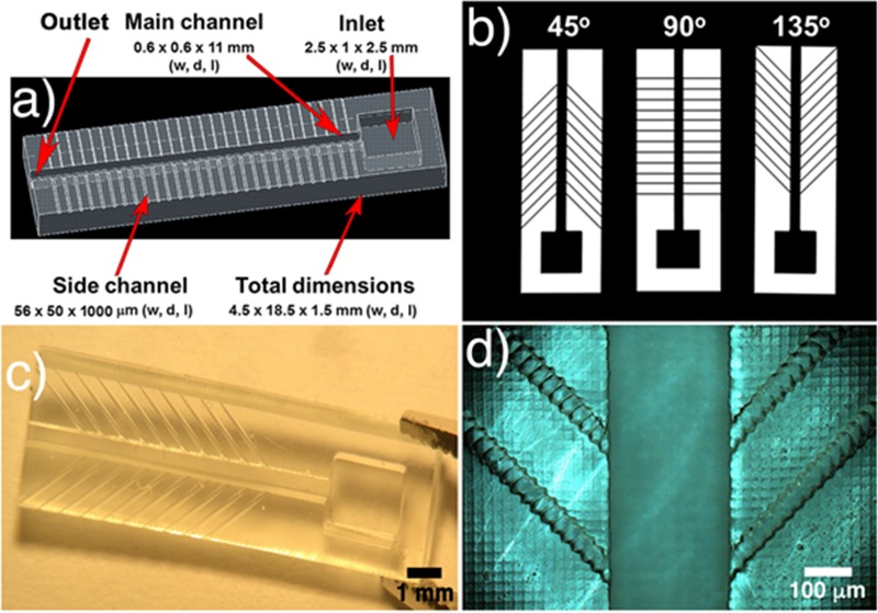
The 3D-printed samples' dimensions were 4.5 × 18.5 × 1.5 mm3 in width, depth and length (w, d, l), respectively (demonstrated in Fig. 1(a)). After printing, the samples were washed with ethanol to remove uncured resin, dried with nitrogen, and post-cured using a printer-integrated UV-Lamp (18 W UVA Lamp) for 600 s.
FIG. 1.
(a) CAD image of a whole filtration structure (showing the inlet/outlet, main channel and side channels); (b) side channels with different angles (45°, 90°, and 135°); (c) real 3D structure with side channels of 135°; and (d) optical microscopic amplification of a 3D-printed structure.
The design of the microfluidic geometry was inspired by the system characterized in the Zweifach-Fung effect paper18,19 and optimized for on-chip plasma separation based on blood capillary flow into the microchannels. All samples had a top inlet with 2.5 × 1 × 2.5 mm3 (w, d, l), a main channel of 0.6 × 0.6 × 11 mm3 (w, d, l) and side channels of 56 × 50 × 1000 μm3 (w, d, l). The outlet was formed by an aperture at the end of the main channel. The side channels had the minimum possible width limited by the 3D printer's resolution (56 μm and 50 μm in w, d). The designs were prepared using all the possible angles to maintain the uniformity of the side channels with only 1 pixel, which is equivalent to 56 μm (45°, 90°, and 135°), and allowing the choice of the optimized angle for developing specific microdevices. The influence of the angles on the velocity and on the filtering process was tested.
The analysis of real printed feature size and comparison to the theoretical dimensions of printing were carried out using an optical microscope (AxioImager, Zeiss, Germany).
As reported in the literature,56 fully 3D-printed closed channels manifest high roughness inside the channel, due to the so-called “back side effect.” The first cured layer that will close the channel cannot be supported by a previously cured layer, leading to an overcuring effect, which in turn deforms the channel inner part (see Figure S.1 in supplementary material). To solve this issue, the open 3D samples were bonded to a flexible planarized polyethylene naphthalate (PEN) substrate PQA1M (Teijin DuPont Films), which has a defect-free surface due to a protective foil and surface energy of 30 mNm−1. The bonding was achieved via inkjet printing a UV-curable PVP-co-PMMA ink, as described in our previous work.47 First, the PQA1M substrate was treated with oxygen plasma (30 W, 0.2 mbar, 0.3 min) (Nano, Diener Electronic GmbH), after which the UV-curable ink was printed using an inkjet printer (OmniJet 300, UniJet Co., the Republic of Korea). The viscosity and surface tension of the ink were adjusted to approximately 10 mPa and 30 mN m−1 to comply with optimal jetting requirements. The printing was done at a jetting frequency of 1 kHz and resolution in the range from 800 to 1700 dpi.
A negative structure replicating the outer dimensions from main and side channels of the 3D-printed microfluidics was printed. Next, the 3D-printed part was accurately positioned using a fineplacer (Finetech Fineplacer Lambda, Finetech GmbH & Co. KG) with a ±1 μm precision. To provide a good cross-linking polymerization and bonding of the samples to the substrate, a curing process with UV light (MUA-165, Mejiro Genossen Inc.; wavelength range: 365 nm–405 nm, 1.1 W cm−2) was used. Bonded samples were left drying in ambient conditions for 24 h to ensure complete evaporation of the ink solvent.
Prior to blood filtering experiments, all the samples were treated with oxygen plasma (10 W, 0.24 mbar for 60 s).
Fresh blood samples were collected from wild-type rats and stored in heparin anticoagulant tubes at 4 °C for 24 h without dilution. During the measurements, 8 μl of heparinized blood was used per analysis.
The filtration characterization and the flow velocity were recorded with a high-speed CCD camera (XiQ, Ximea, Germany) using 300 frames with 50 ms interval, and the data acquisition was made with the μ-Manager plus ImageJ software.
All the others optical analyses were carried out using an AxioImager optical microscope.
III. RESULTS AND DISCUSSION
A. 3D printing
The 3D micro-filter devices were printed as described in Section II. Contact angle measurements using standard curing time of 600 s gained an angle of 68.3 ± 2.1°, n = 3 for deionized water.
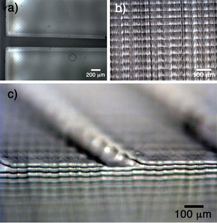
To check the actual printing accuracy vs. theoretical design values, samples with the highest resolution (50 μm in depth and 56 μm in x, y) were analysed. Microscopic top and side views are presented in Fig. 2. In the top view (Fig. 2(a)), one can see uniform, reproducible and defined squares that represent the pixels of the images projected during the printing process. The orientation of the presented pixels affects the printed edges that hinder the fabrication of a perfectly flat structure not orthogonal to the pixel lines. The side view image (Fig. 2(b)) demonstrates a sequence of defined and uniform 50 μm layers. In a tilted view (Fig. 2(c)), both lateral and vertical printing marks are observed. Based on these three figures, it is possible to understand how the 3D printing process occurs: the projected light corresponding to the fed image cures the polymeric resin with a specific depth (side view) and the lateral resolution can be observed by the square pixels on the surface.
FIG. 2.
Different views of the 3D structure are presented: (a) top view, (b) side view, and (c) tilted view.
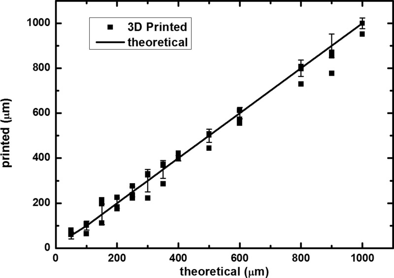
In Fig. 3, a complete relation between theoretical and 3D printed values is presented. The 3D printer showed good correlation even at small scales, with a small deviation of ±8% with n = 3 and a coefficient of variation (or relative standard deviation) of 1.8%, when comparing the dimensions of the real structures with the designed ones. The success rate of printing these devices was close to 100%, once it was possible to print a set of structures per round.
FIG. 3.
Relation between theoretical and 3D printed values.
B. Bonding process
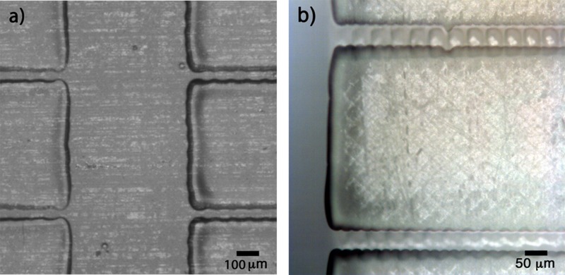
The micro-filter was bonded to PQA1M foil using the UV-curable PVP-co-PMMA ink, as described before. The printed patterned adhesive ink and the device accurately placed on the substrate are illustrated in Fig. 4.
FIG. 4.
(a) PVP-co-PMMA UV-curable ink inkjet printed onto the flexible substrate to form a bonding area replicating the non-functional area of the microfluidic device. (b) 3D-printed microfluidic structure bonded onto PQA1M flexible substrate using inkjet printed PVP-co-PMMA UV-curable ink after positioning using a fineplacer.
Using the accuracy of the proposed method for bonding a 3D-printed structure to a polymeric substrate,47 it could also be possible to print several sensing elements directly onto the flexible substrate and then bond it with a patterned adhesive without affecting the sensor structures, allowing the production of a multi-sensorial microdevice.
C. Blood flow velocity
Important parameters that influence the flow velocity in passive microfluidics are the surface wettability57 and the surface roughness.38,57 Controlling both parameters is essential for designing suitable blood guiding devices, due to the surface interactions with polar and nonpolar groups and also due to the friction factor values. For instance, bovine serum albumin (BSA) adsorbs more easily on highly hydrophobic substrates, decreasing the blood flow velocity.58
To optimize the surface properties, the influence of oxygen plasma treatment on the surface energy was investigated. Without oxygen plasma treatment, blood got stuck at the inlet, not advancing further into the micro-channels (see Figure S.2 in supplementary material). As could be shown in our previous paper,47 the oxygen plasma treatment was able to increase the wettability of the 3D structures, increasing the hydrophilicity and enabling the blood to be sucked into the channels due to capillary forces only, suppressing the undesirable influence of any surface roughness. After process optimization, the plasma treatment parameters were set at 10 W, 0.24 mbar and 1 min. As expected, the contact angle of 5 μl rat blood droplet decreased from 58° to 37° directly after plasma treatment.
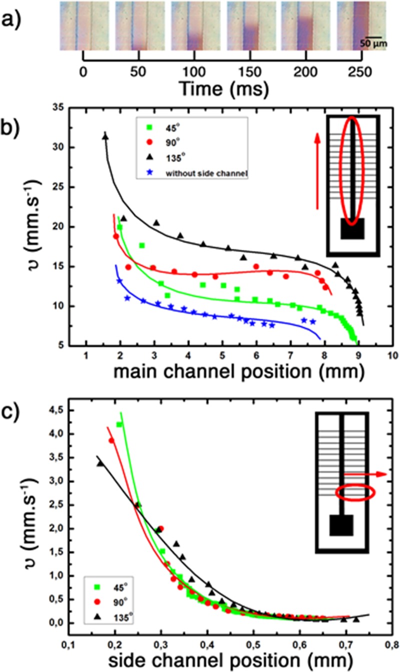
Experiments with blood were conducted using three different side channel angles. An amount of 8 μl of blood was calculated to fill the system completely and be sufficient for the filtration process using the current design. The flow velocity analysis for all cases was performed. The results are shown in the Fig. 5.
FIG. 5.
Blood flow velocity for 8 μl of blood in: (a) capillary flow of blood as a function of time inside the 3D-printed microfluidic channel; (b) velocity at the main channel (with and without side channels); and (c) side channels with 45°, 90°, and 135°, respectively. All the main channels were 0.6 × 0.6 × 11 mm3 (w, d, l) with an inlet of 2.5 × 1 × 2.5 mm3 and oxygen plasma treatment of 10 W, 0.24 mbar during 1 min. Flow velocity recorded with a high velocity CCD camera and acquisition of 300 frames/50 ms of interval.
As shown in Fig. 5(b), the range of fluid velocities in the inlet was between 13 and 30 mm s−1 and, in all cases, had a drop of velocity after the blood entered the channel, reaching a plateau around 3 mm from the inlet and constant velocities between 9 and 17 mm s−1 for the main channel with and without side channels. This variation of velocity occurs because this system does not have an external flow controller (pump, vacuum system or similar) but is controlled solely by the capillary inside the microchannel. With the measured velocities, the blood can instantaneously reach the side channels, starting the filtering process.
In the side channels, one can see the same behaviour as in the main channel. The blood flow loses velocity very fast at the beginning and reaches a plateau of 0.1 mm s−1 around 0.45 mm from start. This position is practically the middle of the side channel, which can be convenient for placing a sensor to perform fast biosensing measurements.
D. Blood plasma filtration tests
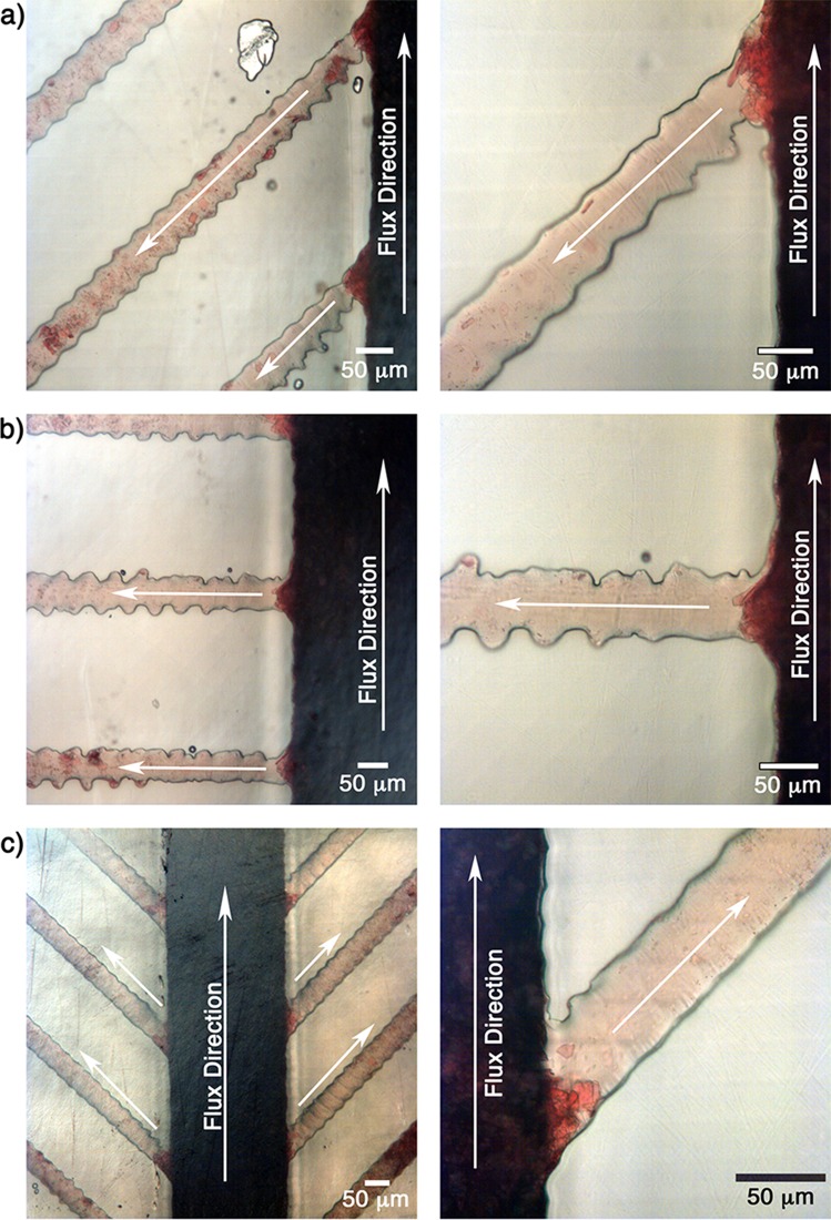
The filtration process for all cases is presented in Fig. 6.
FIG. 6.
Filtration process in the small side channels with angles: (a) 45°, (b) 90°, and (c) 135°. Analysis was performed with 8 μl of blood and oxygen plasma treatment of 10%, 1 min, 0.24 mbar.
In all presented cases, one can observe that the proposed structures were able to filter the plasma from the whole blood. Also, the presence of crystals blocking the entrance of the side channels can be observed. These crystals help in the filtration process by blocking the side channels and retaining RBCs and letting only the plasma pass. This behavior is highly reproducible and was observed in all experiments.
The crystals are originated due to the aggregation of fresh whole blood with heparin.48 The size and amount of crystals have a strong influence on the filtration process/efficiency. Therefore, it is important to emphasize that a minimum of 24 h of blood storage at 4 °C guaranteed uniformity and reproducibility of crystal size and distribution, reaching a reproducible filtering process. The heparin was kept in excess, i.e., at a concentration far exceeding the one recommended by the manufacturer. Comparative tests were made with less than 1 day of storage using a smaller amount of heparin resulted in an amount of crystals insufficient to block the entrance of the side channels, disrupting the filtration process. Therefore, the results indicate that the filtration process is dependent on heparin concentration and also on the storage time. In the supplementary material (Fig. S.3), an optical microscopic image of heparinized blood is shown after one day of storage. The formation of crystals with different sizes and shapes is evident.
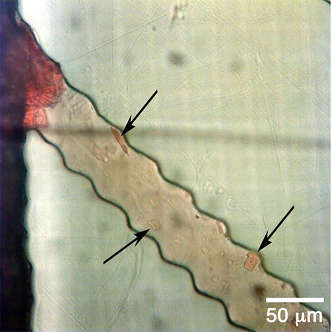
If one looks carefully inside the channels in Fig. 7, the presence of some crystals flowing together with plasma can be identified. This behavior can also be observed in Fig. 8, Video 1 (multimedia view). The possible interference of these crystals with the sensory detection will be analysed in the future work.
FIG. 7.
Crystals flowing together with plasma after filtering.
FIG. 8.
Most side channels have rugged line shaped walls due to the limited pixel resolution of the printing process (as discussed in Fig. 2 and as observed in Figures 6, 7, and 9). However, this geometry did not interfere with the capillary flow or the filtration process compared to channels with straight walls.
FIG. 9.
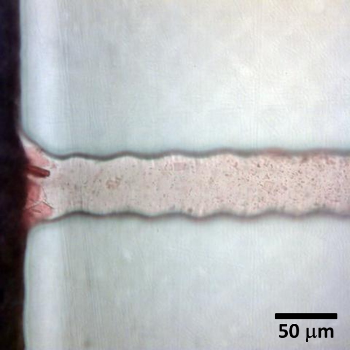
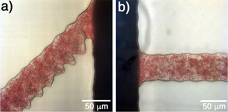
Absence of filtration process when fresh whole blood was added: (a) 45° and (b) 90°. Analysis with 8 μl of fresh blood and oxygen plasma treatment of 10%, 1 min, 0.24 mbar.
Analysis of the oxygen plasma treatment efficiency after 24 and 48 hours was carried out and yielded similar results to those presented above. For periods longer than 48 hours, the treatment started to lose efficiency, compromising the filtering process.
The filtration was not observed if the depth and width of the side channels were increased (for values larger than 50 μm and 56 μm, respectively). Moreover, when fresh blood was fed directly to the filter, the filtration process was inefficient due to the absence of crystals obstructing the side channel entrance. The RBCs passed through the side channels, and after that the coagulation process started immediately, impairing the blood flow, as shown in Fig. 9.
It is important to emphasize that the proposed system uses a single drop of blood (8 μl) and the flow inside the microchannels occurs only due to the capillary effect without external devices. The amount of plasma obtained is sufficient for analysis employing electrochemical or optical sensors, which can be integrated directly onto the polymer substrate. If the amount of plasma is insufficient with the current design, one could reduce the number of side channels, increasing the filtered plasma volume in each microchannel. An important prerequisite for successful filtration is the sufficient storage time and heparin concentration forming enough crystals to block the passage of RBCs, ensuring the filtration efficiency.
IV. CONCLUSIONS
A standalone 3D-printed microfluidic system for passive, i.e., without pumps or vacuum, extraction of plasma from small amounts of whole blood was developed.
The 3D printer presented accurate relation between the designed model and the printed one, making possible the development of microstructures combined with the ink-jet printing for rapid prototyping of microfluidic devices.
The fabricated device showed to be useful for quick and efficient filtration process. Furthermore, printed biosensors could be easily integrated into each micro-channel allowing a wide range of chemical and biochemical analyses in a single on-chip microdevice using a small amount of sample.
V. SUPPLEMENTARY MATERIAL
See supplementary material for the fully 3D-printed closed channels displaying a high roughness inside the channel; a blood drop at the inlet in the 3D microfluidic structures without oxygen plasma treatment; an optical microscopy image of crystals forming as a result of the interaction of blood with heparin; and a video of the filtration process.
ACKNOWLEDGMENTS
The authors acknowledge the funding from the CAPES Foundation, Ministry of Education of Brazil, within the PDSE process 10585-14-1 and Helmholtz Validation Fund within the Project HVF-0034.
References
- 1. Anderson N. L. and Anderson N. G., Mol. Cell. Proteomics 1, 845 (2002). 10.1074/mcp.R200007-MCP200 [DOI] [PubMed] [Google Scholar]
- 2. Whicher J. T., Calvin J., Riches P., and Warren C., Ann. Clin. Biochem. 24(Pt 2), 119 (1987). 10.1177/000456328702400201 [DOI] [PubMed] [Google Scholar]
- 3. Maltezos G., Lee J., Rajagopal A., Scholten K., Kartalov E., and Scherer A., Biomed. Microdevices 13, 143 (2011). 10.1007/s10544-010-9479-1 [DOI] [PubMed] [Google Scholar]
- 4. Homsy A., van der Wal P. D., Doll W., Schaller R., Korsatko S., Ratzer M., Ellmerer M., Pieber T. R., Nicol A., and de Rooij N. F., Biomicrofluidics 6, 12804 (2012). 10.1063/1.3672188 [DOI] [PMC free article] [PubMed] [Google Scholar]
- 5. Hsieh S.-Y., Chen R.-K., Pan Y.-H., and Lee H.-L., Proteomics 6, 3189 (2006). 10.1002/pmic.200500535 [DOI] [PubMed] [Google Scholar]
- 6. Tüdős A. J., Besselink G. A. J., and Schasfoort R. B. M., Lab Chip 1, 83 (2001). 10.1039/B106958F [DOI] [PubMed] [Google Scholar]
- 7. Rogers C. I., Qaderi K., Woolley A. T., and Nordin G. P., Biomicrofluidics 9, 16501 (2015). 10.1063/1.4905840 [DOI] [PMC free article] [PubMed] [Google Scholar]
- 8. Wightman R. M., Science (80-) 311, 1570 (2006). 10.1126/science.1120027 [DOI] [PubMed] [Google Scholar]
- 9. Weng X., Chen L., Neethirajan S., and Duffield T., Biosens. Bioelectron. 72, 140 (2015). 10.1016/j.bios.2015.05.008 [DOI] [PubMed] [Google Scholar]
- 10. Yager P., Edwards T., Fu E., Helton K., Nelson K., Tam M. R., and Weigl B. H., Nature 442, 412 (2006). 10.1038/nature05064 [DOI] [PubMed] [Google Scholar]
- 11. Yang L. and Bashir R., Biotechnol. Adv. 26, 135 (2008). 10.1016/j.biotechadv.2007.10.003 [DOI] [PubMed] [Google Scholar]
- 12. Tay A., Pavesi A., Yazdi S. R., Lim C. T., and Warkiani M. E., Biotechnol. Adv. 34, 404 (2016). 10.1016/j.biotechadv.2016.02.002 [DOI] [PMC free article] [PubMed] [Google Scholar]
- 13. Daniele M. A., Boyd D. A., Mott D. R., and Ligler F. S., Biosens. Bioelectron. 67, 25 (2015). 10.1016/j.bios.2014.07.002 [DOI] [PubMed] [Google Scholar]
- 14. Kim G., Moon J.-H., Moh C.-Y., and Lim J., Biosens. Bioelectron. 67, 243 (2015). 10.1016/j.bios.2014.08.023 [DOI] [PubMed] [Google Scholar]
- 15. Meier H., Löffelmann U., Mager D., Smith P. J., and Korvink J. G., Phys. Status Solidi 206, 1626 (2009). 10.1002/pssa.200925088 [DOI] [Google Scholar]
- 16. Tripathi S., Kumar Y. V. B. V., Prabhakar A., Joshi S. S., and Agrawal A., J. Micromech. Microeng. 25, 83001 (2015). 10.1088/0960-1317/25/8/083001 [DOI] [Google Scholar]
- 17. Lenshof A. and Laurell T., Chem. Soc. Rev. 39, 1203 (2010). 10.1039/b915999c [DOI] [PubMed] [Google Scholar]
- 18. Svanes K. and Zweifach B. W., Microvasc. Res. 1, 210 (1968). 10.1016/0026-2862(68)90019-8 [DOI] [Google Scholar]
- 19. Fung Y.-C., Microvasc. Res. 5, 34 (1973). 10.1016/S0026-2862(73)80005-6 [DOI] [PubMed] [Google Scholar]
- 20. Pamme N., Lab Chip 7, 1644 (2007). 10.1039/b712784g [DOI] [PubMed] [Google Scholar]
- 21. Haeberle S., Brenner T., Zengerle R., and Ducrée J., Lab Chip 6, 776 (2006). 10.1039/B604145K [DOI] [PubMed] [Google Scholar]
- 22. Moorthy J. and Beebe D. J., Lab Chip 3, 62 (2003). 10.1039/b300450c [DOI] [PubMed] [Google Scholar]
- 23. Xiang N. and Ni Z., Biomed. Microdevices 17, 110 (2015). 10.1007/s10544-015-0018-y [DOI] [PubMed] [Google Scholar]
- 24. Yang S., Ündar A., and Zahn J. D., Lab Chip 6, 871 (2006). 10.1039/B516401J [DOI] [PubMed] [Google Scholar]
- 25. Fekete Z., Nagy P., Huszka G., Tolner F., Pongrácz A., and Fürjes P., Sens. Actuators, B 162, 89 (2012). 10.1016/j.snb.2011.12.040 [DOI] [Google Scholar]
- 26. Aran K., Fok A., Sasso L. A., Kamdar N., Guan Y., Sun Q., Ündar A., and Zahn J. D., Lab Chip 11, 2858 (2011). 10.1039/c1lc20080a [DOI] [PMC free article] [PubMed] [Google Scholar]
- 27. Browne A. W., Ramasamy L., Cripe T. P., and Ahn C. H., Lab Chip 11, 2440 (2011). 10.1039/c1lc20144a [DOI] [PubMed] [Google Scholar]
- 28. Sun M., Khan Z. S., and Vanapalli S. A., Lab Chip 12, 5225 (2012). 10.1039/c2lc40544j [DOI] [PubMed] [Google Scholar]
- 29. Lázaro G. R., Hernández-Machado A., and Pagonabarraga I., Soft Matter 10, 7195 (2014). 10.1039/C4SM00894D [DOI] [PubMed] [Google Scholar]
- 30. Chen X., Cui D., and Chen J., Electrophoresis 30, 3168 (2009). 10.1002/elps.200900068 [DOI] [PubMed] [Google Scholar]
- 31. Kim Y. C., Kim S.-H., Kim D., Park S.-J., and Park J.-K., Sens. Actuators, B 145, 861 (2010). 10.1016/j.snb.2010.01.017 [DOI] [Google Scholar]
- 32. Dimov I. K., Basabe-Desmonts L., Garcia-Cordero J. L., Ross B. M., Ricco A. J., and Lee L. P., Lab Chip 11, 845 (2011). 10.1039/C0LC00403K [DOI] [PubMed] [Google Scholar]
- 33. Brody J. P., Osbom T. D., Forster F. K., and Yager P., Sens. Actuators, A 54, 704 (1996). 10.1016/S0924-4247(97)80042-8 [DOI] [Google Scholar]
- 34. Shim J. S., Browne A. W., and Ahn C. H., Biomed. Microdevices 12, 949 (2010). 10.1007/s10544-010-9449-7 [DOI] [PubMed] [Google Scholar]
- 35. Li C., Liu C., Xu Z., and Li J., Biomed. Microdevices 14, 565 (2012). 10.1007/s10544-012-9635-x [DOI] [PubMed] [Google Scholar]
- 36. Tripathi S., Prabhakar A., Kumar N., Singh S. G., and Agrawal A., Biomed. Microdevices 15, 415 (2013). 10.1007/s10544-013-9738-z [DOI] [PubMed] [Google Scholar]
- 37. Tripathi S., Kumar Y. V. B. V., Prabhakar A., Joshi S. S., and Agrawal A., J. Micromech. Microeng. 25, 84004 (2015). 10.1088/0960-1317/25/8/084004 [DOI] [Google Scholar]
- 38. Tripathi S., Kumar Y. V. B., Agrawal A., Prabhakar A., and Joshi S. S., Sci. Rep. 6, 26749 (2016). 10.1038/srep26749 [DOI] [PMC free article] [PubMed] [Google Scholar]
- 39. Prabhakar A., Kumar Y. V. B. V., Tripathi S., and Agrawal A., Microfluid. Nanofluid. 18, 995 (2015). 10.1007/s10404-014-1488-6 [DOI] [Google Scholar]
- 40. O'Neill P. F., Ben Azouz A., Vázquez M., Liu J., Marczak S., Slouka Z., Chang H. C., Diamond D., and Brabazon D., Biomicrofluidics 8, 52112 (2014). 10.1063/1.4898632 [DOI] [PMC free article] [PubMed] [Google Scholar]
- 41. Ambrosi A. and Pumera M., Chem. Soc. Rev. 45, 2740 (2016). 10.1039/C5CS00714C [DOI] [PubMed] [Google Scholar]
- 42. Asano H. and Shiraishi Y., Anal. Chim. Acta 883, 55 (2015). 10.1016/j.aca.2015.04.014 [DOI] [PubMed] [Google Scholar]
- 43. Weng B., Shepherd R. L., Crowley K., Killard A. J., and Wallace G. G., Analyst 135, 2779 (2010). 10.1039/c0an00302f [DOI] [PubMed] [Google Scholar]
- 44. Gonzalez-Macia L., Morrin A., Smyth M. R., and Killard A. J., Analyst 135, 845 (2010). 10.1039/b916888e [DOI] [PubMed] [Google Scholar]
- 45. Weng B., Morrin A., Shepherd R., Crowley K., Killard A. J., Innis P. C., and Wallace G. G., J. Mater. Chem. B 2, 793 (2014). 10.1039/C3TB21378A [DOI] [PubMed] [Google Scholar]
- 46. Li J., Rossignol F., and Macdonald J., Lab Chip 15, 2538 (2015). 10.1039/C5LC00235D [DOI] [PubMed] [Google Scholar]
- 47. Hamad E. M., Bilatto S. E. R., Adly N. Y., Correa D. S., Wolfrum B., Schöning M. J., Offenhäusser A., and Yakushenko A., Lab Chip 16, 70 (2016). 10.1039/C5LC01195G [DOI] [PubMed] [Google Scholar]
- 48. Canterino J. E., Galkin O., Vekilov P. G., and Hirsch R. E., Biophys. J. 95, 4025 (2008). 10.1529/biophysj.107.127324 [DOI] [PMC free article] [PubMed] [Google Scholar]
- 49. Selvam A. P., Muthukumar S., Kamakoti V., and Prasad S., Sci. Rep. 6, 23111 (2016). 10.1038/srep23111 [DOI] [PMC free article] [PubMed] [Google Scholar]
- 50. Khan Y., Pavinatto F. J., Lin M. C., Liao A., Swisher S. L., Mann K., Subramanian V., Maharbiz M. M., and Arias A. C., Adv. Funct. Mater. 26, 1004 (2016). 10.1002/adfm.201503316 [DOI] [Google Scholar]
- 51. Pavinatto F. J., Paschoal C. W. A., and Arias A. C., Biosens. Bioelectron. 67, 553 (2015). 10.1016/j.bios.2014.09.039 [DOI] [PubMed] [Google Scholar]
- 52. Perelaer J., de Gans B.-J., and Schubert U. S., Adv. Mater. 18, 2101 (2006). 10.1002/adma.200502422 [DOI] [Google Scholar]
- 53. Yakushenko A., Schnitker J., and Wolfrum B., Anal. Chem. 84, 4613 (2012). 10.1021/ac300460s [DOI] [PubMed] [Google Scholar]
- 54. Turner A. P. F., Chem. Soc. Rev. 42, 3184 (2013). 10.1039/c3cs35528d [DOI] [PubMed] [Google Scholar]
- 55. Lee H., Sun E., Ham D., and Weissleder R., Nat. Med. 14, 869 (2008). 10.1038/nm.1711 [DOI] [PMC free article] [PubMed] [Google Scholar]
- 56. Shallan A. I., Smejkal P., Corban M., Guijt R. M., and Breadmore M. C., Anal. Chem. 86, 3124 (2014). 10.1021/ac4041857 [DOI] [PubMed] [Google Scholar]
- 57. Sajeesh P. and Sen A. K., Microfluid. Nanofluid. 17, 1 (2014). 10.1007/s10404-013-1291-9 [DOI] [Google Scholar]
- 58. Brancato L., Keulemans G., Gijsenbergh P., and Puers R., Procedia Eng. 87, 336 (2014). 10.1016/j.proeng.2014.11.751 [DOI] [Google Scholar]
Associated Data
This section collects any data citations, data availability statements, or supplementary materials included in this article.
Supplementary Materials
See supplementary material for the fully 3D-printed closed channels displaying a high roughness inside the channel; a blood drop at the inlet in the 3D microfluidic structures without oxygen plasma treatment; an optical microscopy image of crystals forming as a result of the interaction of blood with heparin; and a video of the filtration process.


