

A triboelectric eye blinking sensor with robustly high sensitivity achieves prominence as a human-machine interface.
Abstract
Mechnosensational human-machine interfaces (HMIs) can greatly extend communication channels between human and external devices in a natural way. The mechnosensational HMIs based on biopotential signals have been developing slowly owing to the low signal-to-noise ratio and poor stability. In eye motions, the corneal-retinal potential caused by hyperpolarization and depolarization is very weak. However, the mechanical micromotion of the skin around the corners of eyes has never been considered as a good trigger signal source. We report a novel triboelectric nanogenerator (TENG)–based micromotion sensor enabled by the coupling of triboelectricity and electrostatic induction. By using an indium tin oxide electrode and two opposite tribomaterials, the proposed flexible and transparent sensor is capable of effectively capturing eye blink motion with a super-high signal level (~750 mV) compared with the traditional electrooculogram approach (~1 mV). The sensor is fixed on a pair of glasses and applied in two real-time mechnosensational HMIs—the smart home control system and the wireless hands-free typing system with advantages of super-high sensitivity, stability, easy operation, and low cost. This TENG-based micromotion sensor is distinct and unique in its fundamental mechanism, which provides a novel design concept for intelligent sensor technique and shows great potential application in mechnosensational HMIs.
INTRODUCTION
Human beings have never stopped their pursuit of making their life more convenient and fascinating. A human-machine interface (HMI)—a novel communication channel between a human and an external device—is one way to turn a virtual thought into realistic action. Unlike traditional HMIs as hand operation, speech input, etc., HMIs based on bioelectrical signals (1–4) have advantages of “hands-free” or “aphasia,” especially for patients suffering from amyotrophic lateral sclerosis. To date, the bioelectrical signals applied to HMIs include neuron signals (1, 2, 5), as well as electrocorticogram (6), electroencephalogram (EEG) (3), electromyogram (EMG) (7), electrooculogram (EOG) signals (8–10), etc. Among these techniques, EEG, EMG, and EOG are noninvasive. EEG-based HMI is the most commonly used method and has been proven useful for paralyzed patients to communicate with the external world to relatively low cost (3, 11). However, the low signal-to-noise ratio (SNR) of the scalp-recorded EEG signals (in microvolts), the lack of efficient resolution in modeling, and consequently higher requirements for the classification algorithm (12, 13), as well as a long period of training, limit the wide use of EEG-based HMIs (14). Furthermore, a multielectrode with electrolyte gel [usually named “wet electrode” (15)] takes much time to prepare, and the gel can only keep excellent electrical conductivity for 2 hours. These drawbacks make EEG-based HMIs stable only under favorable laboratory conditions, and unstable in daily life because of various disturbances, including mechanical artifacts such as EMG and EOG signals (4). Nevertheless, EMG and EOG can be used as good control signals for healthy people and even “lock-in” patients who could still blink their eyes (16). As to these people, EMG and EOG techniques are more practical for everyday situations than EEG-based HMIs (4, 16). In particular for EOG, it is a technique serving both healthy and disabled persons. EOG is based on signal collection from the corneal-retinal potential difference in the process of eye movements. The fundus is usually defined as the negative pole and the cornea as the positive pole (17). The potential difference is determined in principle at least on two exposed electrodes (usually Ag/AgCl electrodes as wet electrodes) pasted around the sensitive eyes, which bring discomfort and poor aesthetics. In addition, the amplitude of EOG is very weak, ranging between 50 μV and 3.5 mV (17), which is often masked by noise and difficult to detect without sophisticated and expensive electronics. Also, as for these weak signals, facial muscle movement can easily produce artifacts (17). Therefore, EOG would be inappropriate for some applications, such as driving a car, piloting a plane, or operating a motorized wheelchair. A noninvasive and sensitive aesthetic sensor that is usable, stable, and comfortable is desired for serving the particular groups of people discussed above to solve these problems in bioelectrical-based HMI systems.
In recent years, the fast development of nanotechnology has provided possible strategies for problems in the field of bioelectric signal collection and HMIs (18–20). Among these technologies, a new system—the triboelectric nanogenerator (TENG) (21–24)—was invented and quickly developed on the basis of contact electrification and electrostatic induction (25, 26), with unique advantages of high output, low cost, light weight, applicability of structure design, prominent stability, robustness, etc. (27–30). Because TENGs can generate electricity from almost all types of mechanical motions, including touching (31), sliding (32, 33), rotation (34, 35), vibration (36), etc., they can serve as self-powered sensors for a similarly wide range of motions, such as touch/pressure sensors (37), vibration sensors (38), biomechanical sensors (39), electronic skin sensors (40), acoustic sensors (41), pulse wave sensors (42), synthesized multifunctional sensors (43), and more. For the pulse wave sensor, Yang et al. (42) have reported a bionic membrane sensor that noninvasively monitors the extremely weak arterial pulse from the subject’s carotid artery, chest, and wrist. This inspired us to consider whether a TENG-based micromotion sensor could be used as a novel sensing device as an alternative to traditional EOG technique and could make a significant breakthrough on the mechnosensational HMI.
Here, a noninvasive, highly sensitive (~750 mV), easy-to-fabricate, stable, small, light, transparent, flexible, skin-friendly, low-cost, durable, and reusable TENG-based sensor for translating the real-time micromotion of eye blink into control command is presented. This mechnosensational TENG (msTENG) [as a sensor, it can be regarded as a type of the present ongoing “dry electrode” (15, 19)] with a multifilm structure is designed on the basis of a single-electrode mode and thus could be flexibly mounted and hidden behind an eyeglass arm to form a wearable sensor (44). The voltage curves of the device with different parameter structures are tested systematically, and synchronous measurement illustrates that voltage amplitude from the msTENG is significantly larger (hundred times) than that from an EOG. On the basis of this high sensitivity, the as-fabricated msTENG smart sensor glasses are used to control household appliances with a simple signal processing circuit. Furthermore, a wireless module is introduced to develop a hands-free virtual keyboard typing system. This work for the first time brings a TENG-based sensor to the field of mechnosensational HMIs, and it promises to make a significant breakthrough on mechnosensational HMIs in conditions of daily life.
RESULTS
As illustrated in Fig. 1A, the circular msTENGs are mounted on the inner side arms of ordinary glasses with adjustable fixators in consideration of invisibility, aesthetics, and convenience. The small fixator (Fig. 1A, 1) assembled with two acrylic sheets, two screws, and two springs provides a flexible mechanical support for the msTENGs. The msTENG (Fig. 1A, 2) designed in the single-electrode mode has a multilayered structure using a thin layer of polyethylene terephthalate (PET) in a tadpole-like shape as a supporting substrate. A fluorinated ethylene propylene (FEP) thin film as one electrification layer coated with indium tin oxide (ITO) as the back electrode is laminated onto the PET substrate. The natural latex used as the opposite electrification layer, which will contact the skin near the eyes, is located on the top. Compared with other thin films, such as nylon and synthetic latex, the natural latex has advantages of super-high elasticity, high tensile strength, air permeability, durability, and being skin-friendly for sensitive eyes. To realize vertical contact/separation, we tightly attached an acrylic thin annulus as a spacer between the natural latex film and the FEP layer. The thickness and diameter of the annulus will determine the pressure detection limit and range of the msTENG. The tiny cylindrical cavity formed between the natural latex and FEP serves as an air spacer for the charge generation and transfer. Five pores with diameters of 0.5 mm are punched through the PET, ITO, and FEP layers, acting as air breathing channels. Fabrication of the TENG-based sensor is described in the Materials and Methods section. Photographs in Fig. 1 (B to D) illustrate a pair of glasses mounted with msTENG on its arms, the simple fixator, and the flexible and transparent msTENG (transmittance is shown in fig. S1). To enhance triboelectrification, we created vertically aligned polymer nanowires onto the FEP surface for better contact with the natural latex. A scanning electron microscopy (SEM) image of FEP nanowires is shown in Fig. 1A2 (inset).
Fig. 1. Structure, and working mechanism of the msTENG.
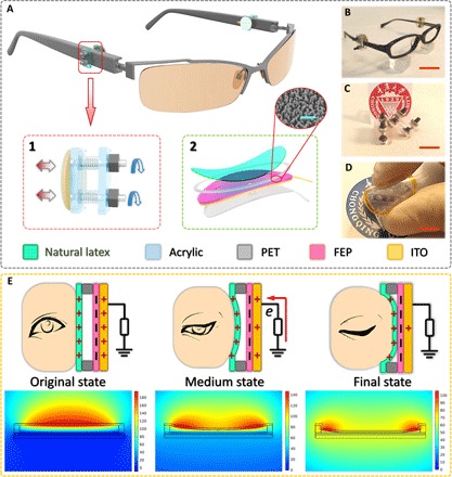
(A) Schematic structure of a pair of ordinary glasses mounted with msTENG. Bottom left: Structure of the fixing device for convenient adjustment. Bottom right: Schematic diagram of the msTENG. Inset: An SEM image of FEP nanowires. Scale bar, 5 μm. (B) Photograph of an ordinary glasses mounted with an as-fabricated msTENG. Scale bar, 2 cm. (C and D) Photographs of the simple fixator (C) and the flexible and transparent msTENG (D). Scale bars, 1 cm. (E) Schematics of the operating principle of msTENG. Top: Charge behavior when the eye is at different states during the blinking process. Bottom: Potential simulation by COMSOL to elucidate the working principle.
The working principle of the msTENG is based on the coupling of contact electrification and electrostatic induction. The electricity generation process when the eye is blinking is illustrated in Fig. 1E. Here, both the schematic diagram of charge distribution (top) and simulation of potential distribution by COMSOL (bottom) are presented. In the original eye-open stage, there are positive charges on the natural latex and negative charges on FEP, which are obtained by several friction cycles between the natural latex and FEP layers. In the middle stage of the eye-blinking process, the muscle around the eye pushes the natural latex film close to the FEP layer. As the potential difference between the two layers gradually becomes lower, the electrons flow to the ITO electrode from the ground in the external circuit. When the eye is fully closed at the final stage, the natural latex film is then in contact with the FEP layer in a large area, so the bound charges are almost in neutralization. Consequently, because there is almost no potential difference across the ITO electrode and ground, the electron flow stops, and then, when the eye is back to open stage, there is an opposite current flowing in the external circuit. This is the full cycle of the electricity generation process.
To characterize the performance of the msTENG sensor, a computer-controlled linear motor and a force gauge are used. At the skin-contact side of msTENG, a silicon rubber pad is used to simulate the skin, and it is fixed on a linear motor tip to apply pressure uniformly onto the natural latex film. Meanwhile, at the other side of the msTENG, a small glass plate with the same dimension is placed between the PET substrate and the tip of the force gauge. As shown in Fig. 2A, the applied pressures and corresponding output voltage under variable deformation degrees from 0.8 to 1.0 mm are measured at a contact-separate frequency of 0.5 Hz. In a cycle of the dynamic deformation, increasing and decreasing pressure is realized through a linear motor, which simulates the deformation induced by eye blinking. From the curves in Fig. 2A, we can see that stronger blinking induces a better signal. To further investigate the frequency response and stability of the msTENG, we measured the voltage signals under an applied pressure of 1 N at deformation frequencies of 0.5, 1.0, 1.5, 2.0, and 3.0 Hz (Fig. 2B). Short-circuit current at different frequencies and a durability test for 10,000 cycles are shown in figs. S2 and S3, respectively. The voltage amplitude reveals a high repeatability, stability, and durability of the msTENG. It is also noted that both the open-circuit voltage and the load voltage increase significantly with a rise in frequency, meaning that a stronger signal can be obtained when the eye blinks faster. To summarize the results of Fig. 2 (A and B), we can conclude that voluntary and fast blinking is different from an involuntary light blink (to be discussed later in the paper), showing that the msTENG has great potential in stable and reliable mechnosensational controlling.
Fig. 2. Characterizing the performance of msTENG.
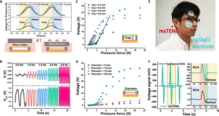
(A) Measurement of the force and output voltage under variable deformation degrees from 0.8 to 1.0 mm. In this measurement, silicon rubber was used to simulate the skin. (B) Load voltage (top) and open-circuit voltage (bottom) of the msTENG under different deformation frequency from 0.5 to 3.0 Hz. (C and D) The influence of gap distance (C) and area size (D). (E) Demonstration of eye movement signal acquisition through msTENG versus EOG. (F) Synchronous measurement of voltage signals from msTENG and EOG. Top right: Compressed curve from msTENG. Bottom right: Enlarged curve from EOG.
Furthermore, the influence of gap and area size of the air spacer in the msTENG is evaluated (Fig. 2, C and D, respectively). The dynamic pressure is applied with a constant frequency of 1 Hz. Figure 2C shows that when a light force (for example, <2 N) is applied, the msTENG is more sensitive to that force when there is a smaller gap (a larger output voltage under the same force). On the other hand, a smaller gap means a smaller linear range and quicker saturation. Notably, when the gap is relatively large (such as 0.8 mm in Fig. 2C), voltage versus pressure response curve exhibits two distinct regions with different slopes. To theoretically explain the result, we used the finite element method (FEM) to simulate the approaching and contacting process. The result is shown in fig. S4, which matches well the experimental results. In Fig. 2C, in the low–applied pressure region (<4 N), a lower pressure sensitivity is experimentally observed, whereas in the high-pressure region (>4 N), well-behaved linear variation in the output voltage shows a superior pressure sensitivity. This tells us that the msTENG can be used as a microforce (also, deformation or motion) sensor, and different gaps are needed to make the msTENG work in linear range in different applications. For the area size of the air spacer, Fig. 2D shows that higher sensitivity to force is obtained under a larger area, but the voltage curve is quicker to saturation. To summarize the results of Fig. 2 (C and D), a larger area size and a smaller gap create superior sensitivity to the microdeformation caused by blinking.
Synchronous measurement is taken to compare the output sensitivity of the as-fabricated msTENG with traditional EOG. Figure 2E illustrates the sensor placement method for msTENG and EOG. For the msTENG, one skin-friendly sensor is concealed on the eyeglass arms, whereas for the EOG, two exposed Ag/AgCl electrodes are firmly pasted around sensitive eyes, which would lead to dim sight because of the connecting lead (the principle of EOG measurement is shown in fig. S5). A real-time profile of the output voltage from msTENG and EOG is demonstrated in Fig. 2F. The insets show a compressed view of the msTENG signal (top) and an enlarged view of the EOG signal (bottom) in one cycle, indicating that an output signal from msTENG is much larger (more than 750 times) than that from EOG within the same response time. This result demonstrates the high sensitivity of the msTENG, and it is superior to any EOG reported in literature. A super-high sensitivity in an equal response time warrants the use of the msTENG to detect micromotions of eye blinking as a control signal in HMI.
On the basis of the strong advantages of the msTENG demonstrated above, we develop a smart home control system, comprised of a person, a pair of glasses mounted with the msTENG, a simple signal processing circuit, and some electrical appliances, such as a table lamp, an electric fan, and a doorbell (Fig. 3A). The signal processing circuit consists of three parts: a 50-Hz notch filter to eliminate power-line interference, an AD623-based instrumentation amplifier to amplify the filtered signal to drive a relay, and a latching relay based on a single-chip microcomputer (SCM). For conditioning other signals such as EEG, EOG, etc., the circuit should always include more parts (10), aside from those illustrated above because of their poor SNR. Three small real circuit boards (≤5 × 5 cm) are shown in Fig. 3B (a detailed diagram is shown in fig. S6). The procedure of signal processing based on these circuits is presented in Fig. 3C. From top to bottom, the first signal is the original blinking signal from the msTENG, followed by the signals after being filtered, amplified, and relay-converted, respectively. Then, the output terminal of latching relay is connected in series with the electrical appliances (lamp, fan, or bell, as shown in Fig. 3D) and a power outlet. When a user is blinking, the signal detected by the msTENG attached to the skin of the in-task eye is conditioned and converted into a switching signal for the electrical appliances (Fig. 3D and movies S1 to S3). This demonstration presents many potential applications for the msTENG in daily life, such as hands-free phone answering while driving, ringing a doorbell when a person’s two hands are fully occupied, self-care for the disabled, and so on. The msTENG functions as the extra hand you always dream of.
Fig. 3. Application of the msTENG in smart home control for both healthy and disabled people.
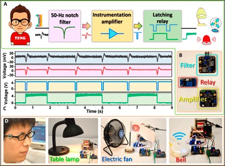
(A) Scheme diagram of an msTENG-involved smart home control system. After simple filtering and amplifying, a blinking signal can be converted into a trigger signal to control the appliances. (B) The circuits for signal conditioning. (C) From top to bottom, the first signal is the original blinking signal from the msTENG, and as follows are the signals after being filtered, amplified, and converted, respectively. (D) Demonstration of the controlling of a table lamp, an electric fan, and a doorbell.
To make the msTENG easier to use, a wireless transceiver module is utilized, and then, a hands-free typing system (typing with eye blinking) is developed (Fig. 4A). Figure 4B shows the smart sensor glasses fabricated with the transmitter module. All the devices in this sensor system are of small sizes and could be encased in a specially designed glasses frame in the future. An eye blink signal from the receiver has a delay of 14.45 ms compared with a wire signal in synchronous measurement (Fig. 4C), which would not affect common operations in daily life. The typing system is designed on the basis of the virtual instrument software platform LabVIEW as a virtual keyboard in the front panel (Fig. 4E). On this keyboard, all the letters (A to Z) and a spacebar (“_”, set after “JK,” as shown in Fig. 4E) are divided into nine groups. The blue cursor keeps shifting to each of these groups at a certain speed [for example, 1000 ms per group, set in a box of “Cursor (ms)”]. To select a letter in a group when the cursor is shifting on it, the user is supposed to voluntarily blink over a specified period of time [for example, 1000 ms, set in a box of “Detect (ms)”]: once, the first letter will be typed to the above textbox; twice, the second letter; and thrice, the third letter (a query table is illustrated in table S1). Because of a high spelling success rate (table S2), “backspace” and “clear” are rarely used. Thus, the strategies for “backspace” and “clear” are designed as four and five consecutive voluntary blinks, instead of adding an extra group labeled “backspace” and “clear” on the screen, which may affect the concision and the spelling efficiency. Furthermore, a more complete scheme of a virtual full keyboard with two channels (for both eyes) is preliminarily framed (fig. S7). The threshold to classify a blink as voluntary or not can be adjusted according to each individual. The process flow of the whole typing system is illustrated in fig. S8. In Fig. 4E, the word “TENG” has been typed with eye blinking by a user. Each signal corresponding to a certain letter is enlarged in Fig. 4D, from which we could understand the operating process and attest the significant difference between voluntary and involuntary blink, as predicted in Fig. 2. To verify the performance of this wireless virtual keyboard typing system, a user with two trials to find the best msTENG placement demonstrates a simple operation process (Fig. 4F and movie S4) and successfully typed the sentence “HELLO TENG” in the textbox. Excellent performance of this system could be proof for the msTENG as a super-sensitive sensor to be applied in computer control. We believe that on the basis of the msTENG, many kinds of mechnosensational computer games will spring out to make life more fascinating.
Fig. 4. Application of the msTENG in a hands-free typing system.
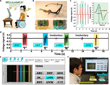
(A) Sketch of the msTENG as a way to help people suffering from “locked-in syndrome” to communicate with the world. (B) The msTENG glasses are assembled with wireless transceiver module to make it easier to use. (C) Synchronous acquisition of wired (green) versus wireless (red) signal. (D) Correspondence between signals and letters typed in the demonstration of a hands-free typing system (E) with adjustable threshold, detecting time, and cursor shift interval. (F) Demonstration of the msTENG-based hands-free wireless typing system. The words on the screen are typed with eye blinking.
DISCUSSION
Nowadays, keeping pace with the rapid development of artificial intelligence is an important and urgent task for the sensor technology. Here, we have developed a TENG-based, highly sensitive, noninvasive micromotion sensor that is skin-friendly, reusable, small, and light to translate eye blink to control command for HMIs and have mounted it on the arms of glasses to construct two practical HMI systems—the smart home control system and the hands-free typing system. Both systems performed extremely well on the basis of simple hardware circuit and software program. These systems are merely ordinary demonstrations that bring us inspiration to apply new technology to a traditional research field. To benefit from TENG, the msTENG sensor is distinct and unique in its fundamental mechanism, which can effectively avoid problems, such as poor SNR and inconvenient operation in mechnosensational HMIs. Moreover, considering the easy fabrication process and the common materials used, the msTENG sensor is cost-effective and suitable for mass production to serve people dependent on ambient intelligence. With the innovative assembly of msTENGs in different body places, people can foresee great potential of TENG-based sensors in intelligent robotics.
MATERIALS AND METHODS
Fabrication of the TENG-based sensor
The fabrication process of the msTENG started from a piece of PET slice. Typically, a PET film (thickness, ~0.2 mm) was cut into tadpole-like pieces (head, diameter of 15 mm; tail, rectangle of 5 × 2 mm) to act as the substrate and the single electrode using a laser cutter after depositing an ITO layer (~50 nm) by electron beam deposition. Then, a nanostructured FEP film (thickness, 20 μm; etched by inductively coupled plasma–reactive ion etching) was adhered over the ITO layer to work as the negative tribolayer. It should be noted that several pores should be created on the as-prepared bottom slice to avoid forming an enclosed chamber. Later, a PET film (thickness, ~0.2 mm) was cut into an annulus (outer diameter, 15 mm; inner diameter, 13 mm), followed by covering a natural latex film (thickness, 0.05 mm) to work as the positive tribolayer. Finally, the as-prepared two parts were assembled to msTENG.
Signal processing circuit
To convert the raw signal into a command, it is necessary to filter the power-line interference and to amplify the filtered signal. First, a two-stage twin-T 50-Hz notch filter with tunable Q-factor (a detailed diagram is shown in fig. S6) was adopted. Then, the filtered signal was amplified by an AD623-based instrumentation amplifying circuit with tunable magnification and dc bias (fig. S6). All the parameters were adjusted carefully to meet the needs of command translation. The commercial latching relay based on a programmed SCM was easy to be driven by the processed signal.
Characterization and measurement
Field-emission SEM (Hitachi SU8010) was used to characterize the surface morphology of the nanostructured FEP film. For the electric output measurement of the TENG-based sensor, a linear motor (LinMot E1100) was used to form alternative motions and drive the sensor to contact and separate for quantified measurement. Meanwhile, a force meter was also used to measure the corresponding pressure force. A programmable electrometer (Keithley 6514) was adopted to test the open-circuit voltage and short-circuit current. In addition, NI 6259 was used to collect data. A software platform was constructed on the basis of LabVIEW, which is capable of realizing real-time data acquisition control and analysis.
Supplementary Material
Acknowledgments
Funding: This research was supported by the National Natural Science Foundation of China (51572040), the Natural Science Foundation of Chongqing (cstc2014jcyjA50030), the Fundamental Research Funds for the Central Universities (CQDXWL-2014-001), and the National High Technology Research and Development Program (863 Program) of China (2015AA034801). Author contributions: X.P., H.G., C.H., and Z.L.W. conceived the idea and designed the msTENG. X.P. and H.G. fabricated the msTENG and designed and performed the experiments. X.P., H.G., C.H., and Z.L.W. analyzed the data and prepared the manuscript. All authors discussed the results and commented on the manuscript. Competing interests: Z.L.W., C.H., X.P., and H.G. are authors on a patent application related to this work, filed with the State Intellectual Property Office of the P. R. China (serial no. 2017061400947090, application no. 201710445108.5; filed on 14 June 2017). The other authors declare that they have no competing interests. Data and materials availability: All data needed to evaluate the conclusions in the paper are present in the paper and/or the Supplementary Materials. Additional data related to this paper may be requested from the authors.
SUPPLEMENTARY MATERIALS
Supplementary material for this article is available at http://advances.sciencemag.org/cgi/content/full/3/7/e1700694/DC1
fig. S1. Transmittance spectra of the msTENG.
fig. S2. Short-circuit current curve of the msTENG under various working frequencies.
fig. S3. Durability test of the msTENG during 10,000 working cycles.
fig. S4. The voltage distribution on the sensor under different displacements by FEM simulation in Fig. 2C.
fig. S5. Principle of EOG measurement.
fig. S6. Main circuit diagrams for conditioning signal from TENG.
fig. S7. Virtual full keyboard with grouping strategy.
fig. S8. Process flow of the typing system.
table S1. Query table for eye blink typing.
table S2. Success rate of the eye blink typing test.
movie S1. Demonstration of the msTENG in controlling a table lamp.
movie S2. Demonstration of the msTENG in controlling an electric fan.
movie S3. Demonstration of the msTENG in controlling a doorbell.
movie S4. Demonstration of the msTENG-based hands-free wireless typing system.
REFERENCES AND NOTES
- 1.Hochberg L. R., Turning thought into action. N. Engl. J. Med. 359, 1175–1177 (2008). [DOI] [PubMed] [Google Scholar]
- 2.Hochberg L. R., Bacher D., Jarosiewicz B., Masse N. Y., Simeral J. D., Vogel J., Haddadin S., Liu J., Cash S. S., van der Smagt P., Donoghue J. P., Reach and grasp by people with tetraplegia using a neurally controlled robotic arm. Nature 485, 372–375 (2012). [DOI] [PMC free article] [PubMed] [Google Scholar]
- 3.Birbaumer N., Ghanayim N., Hinterberger T., Iversen I., Kotchoubey B., Kubler A., Perelmouter J., Taub E., Flor H., A spelling device for the paralysed. Nature 398, 297–298 (1999). [DOI] [PubMed] [Google Scholar]
- 4.Lebedev M. A., Nicolelis M. A. L., Brain–machine interfaces: Past, present and future. Trends Neurosci. 29, 536–546 (2006). [DOI] [PubMed] [Google Scholar]
- 5.Hochberg L. R., Serruya M. D., Friehs G. M., Mukand J. A., Saleh M., Caplan A. H., Branner A., Chen D., Penn R. D., Donoghue J. P., Neuronal ensemble control of prosthetic devices by a human with tetraplegia. Nature 442, 164–171 (2006). [DOI] [PubMed] [Google Scholar]
- 6.Leuthardt E. C., Schalk G., Wolpaw J. R., Ojemann J. G., Moran D. W., A brain-computer interface using electrocorticographic signals in humans. J. Neural Eng. 1, 63–71 (2004). [DOI] [PubMed] [Google Scholar]
- 7.Okuno R., Yoshida M., Akazawa K., Compliant grasp in a myoelectric hand prosthesis. IEEE Eng. Med. Biol. Mag. 24, 48–56 (2005). [DOI] [PubMed] [Google Scholar]
- 8.Guo X., Pei W., Wang Y., Chen Y., Zhang H., Wu X., Yang X., Chen H., Liu Y., Liu R., A human-machine interface based on single channel EOG and patchable sensor. Biomed. Signal Process. Control 30, 98–105 (2016). [Google Scholar]
- 9.Belkacem A. N., Shin D., Kambara H., Yoshimura N., Koike Y., Online classification algorithm for eye-movement-based communication systems using two temporal EEG sensors. Biomed. Signal Process. Control 16, 40–47 (2015). [Google Scholar]
- 10.Usakli A. B., Gurkan S., Design of a novel efficient human–computer interface: An electrooculagram based virtual keyboard. IEEE Trans. Instrum. Meas. 59, 2099–2108 (2010). [Google Scholar]
- 11.Chen X., Wang Y., Nakanishi M., Gao X., Jung T.-P., Gao S., High-speed spelling with a noninvasive brain–computer interface. Proc. Natl. Acad. Sci. U.S.A. 112, E6058–E6067 (2015). [DOI] [PMC free article] [PubMed] [Google Scholar]
- 12.Zhang T., Liu T., Li F., Li M., Liu D., Zhang R., He H., Li P., Gong J., Luo C., Yao D., Xu P., Structural and functional correlates of motor imagery BCI performance: Insights from the patterns of fronto-parietal attention network. Neuroimage 134, 475–485 (2016). [DOI] [PubMed] [Google Scholar]
- 13.Speier W., Arnold C., Pouratian N., Integrating language models into classifiers for BCI communication: A review. J. Neural Eng. 13, 031002 (2016). [DOI] [PMC free article] [PubMed] [Google Scholar]
- 14.Wolpaw J. R., Birbaumer N., McFarland D. J., Pfurtscheller G., Vaughan T. M., Brain–computer interfaces for communication and control. Clin. Neurophysiol. 113, 767–791 (2002). [DOI] [PubMed] [Google Scholar]
- 15.Forvi E., Bedoni M., Carabalona R., Soncini M., Mazzoleni P., Rizzo F., O’Mahony C., Morasso C., Cassarà D. G., Gramatica F., Preliminary technological assessment of microneedles-based dry electrodes for biopotential monitoring in clinical examinations. Sens. Actuators A Phys. 180, 177–186 (2012). [Google Scholar]
- 16.Birbaumer N., Brain–computer-interface research: Coming of age. Clin. Neurophysiol. 117, 479–483 (2006). [DOI] [PubMed] [Google Scholar]
- 17.Barea R., Boquete L., Mazo M., Lopez E., System for assisted mobility using eye movements based on electrooculography. IEEE Trans. Neural Syst. Rehabil. Eng. 10, 209–218 (2003). [DOI] [PubMed] [Google Scholar]
- 18.Someya T., Bao Z., Malliaras G. G., The rise of plastic bioelectronics. Nature 540, 379–385 (2016). [DOI] [PubMed] [Google Scholar]
- 19.Jeong J.-W., Yeo W.-H., Akhtar A., Norton J. J. S., Kwack Y.-J., Li S., Jung S.-Y., Su Y., Lee W., Xia J., Cheng H., Huang Y., Choi W.-S., Bretl T., Rogers J. A., Materials and optimized designs for human-machine interfaces via epidermal electronics. Adv. Mater. 25, 6839–6846 (2013). [DOI] [PubMed] [Google Scholar]
- 20.Xie C., Hanson L., Xie W., Lin Z., Cui B., Cui Y., Noninvasive neuron pinning with nanopillar arrays. Nano Lett. 10, 4020–4024 (2010). [DOI] [PMC free article] [PubMed] [Google Scholar]
- 21.Zhu G., Chen J., Liu Y., Bai P., Zhou Y. S., Jing Q., Pan C., Wang Z. L., Linear-grating triboelectric generator based on sliding electrification. Nano Lett. 13, 2282–2289 (2013). [DOI] [PubMed] [Google Scholar]
- 22.Zhu G., Chen J., Zhang T., Jing Q., Wang Z. L., Radial-arrayed rotary electrification for high performance triboelectric generator. Nat. Commun. 5, 3426 (2014). [DOI] [PubMed] [Google Scholar]
- 23.Zhu G., Peng B., Chen J., Jing Q., Wang Z. L., Triboelectric nanogenerators as a new energy technology: From fundamentals, devices, to applications. Nano Energy 14, 126–138 (2015). [Google Scholar]
- 24.Wang Z. L., Chen J., Lin L., Progress in triboelectric nanogenerators as a new energy technology and self-powered sensors. Energy Environ. Sci. 8, 2250–2282 (2015). [Google Scholar]
- 25.Horn R. G., Smith D. T., Contact electrification and adhesion between dissimilar materials. Science 256, 362–364 (1992). [DOI] [PubMed] [Google Scholar]
- 26.Baytekin H. T., Patashinski A. Z., Branicki M., Baytekin B., Soh S., Grzybowski B. A., The mosaic of surface charge in contact electrification. Science 333, 308–312 (2011). [DOI] [PubMed] [Google Scholar]
- 27.Chen J., Zhu G., Yang W., Jing Q., Bai P., Yang Y., Hou T. C., Wang Z. L., Harmonic-resonator-based triboelectric nanogenerator as a sustainable power source and a self-powered active vibration sensor. Adv. Mater. 25, 6094–6099 (2013). [DOI] [PubMed] [Google Scholar]
- 28.Guo H., Chen J., Yeh M.-H., Fan X., Wen Z., Li Z., Hu C., Wang Z. L., An ultrarobust high-performance triboelectric nanogenerator based on charge replenishment. ACS Nano 9, 5577–5584 (2015). [DOI] [PubMed] [Google Scholar]
- 29.Guo H., Yeh M. H., Lai Y.-C., Zi Y., Wu C., Zhen W., Hu C., Wang Z. L., All-in-one shape-adaptive self-charging power package for wearable electronics. ACS Nano 10, 10580–10588 (2016). [DOI] [PubMed] [Google Scholar]
- 30.Wen Z., Yeh M.-H., Guo H., Wang J., Zi Y., Xu W., Deng J., Zhu L., Wang X., Hu C., Zhu L., Sun X., Wang Z. L., Self-powered textile for wearable electronics by hybridizing fiber-shaped nanogenerators, solar cells, and supercapacitors. Sci. Adv. 2, e1600097 (2016). [DOI] [PMC free article] [PubMed] [Google Scholar]
- 31.Zhu G., Yang W. Q., Zhang T., Jing Q., Chen J., Zhou Y. S., Bai P., Wang Z. L., Self-powered, ultrasensitive, flexible tactile sensors based on contact electrification. Nano Lett. 14, 3208–3213 (2014). [DOI] [PubMed] [Google Scholar]
- 32.Guo H., Qiang L., He X., Wang M., Chen J., Hu C., Yi X., A triboelectric generator based on checker-like interdigital electrodes with a sandwiched PET thin film for harvesting sliding energy in all directions. Adv. Energy Mater. 5, 1400790 (2015). [Google Scholar]
- 33.Wen Z., Chen J., Yeh M.-H., Guo H., Li Z., Fan X., Zhang T., Zhu L., Wang Z. L., Blow-driven triboelectric nanogenerator as an active alcohol breath analyzer. Nano Energy 16, 38–46 (2015). [Google Scholar]
- 34.Guo H., Chen J., Leng Q., Xi Y., Wang M., He X., Hu C., Spiral-interdigital-electrode-based multifunctional device: Dual-functional triboelectric generator and dual-functional self-powered sensor. Nano Energy 12, 626–635 (2015). [Google Scholar]
- 35.Meng X. S., Li H. Y., Zhu G., Wang Z. L., Fully enclosed bearing-structured self-powered rotation sensor based on electrification at rolling interfaces for multi-tasking motion measurement. Nano Energy 12, 606–611 (2015). [Google Scholar]
- 36.Liu G., Guo H., Chen L., Wang X., Wei D., Hu C., Double-induced-mode integrated triboelectric nanogenerator based on spring steel to maximize space utilization. Nano Res. 9, 3355–3363 (2016). [Google Scholar]
- 37.Chen J., Zhu G., Yang J., Jing Q., Bai P., Yang W., Qi X., Su Y., Wang Z. L., Personalized keystroke dynamics for self-powered human–machine interfacing. ACS Nano 9, 105–116 (2015). [DOI] [PubMed] [Google Scholar]
- 38.Liang Q., Zhanga Z., Yan X., Gu Y., Zhao Y., Zhang G., Lu S., Liao Q., Zhang Y., Functional triboelectric generator as self-powered vibration sensor with contact mode and non-contact mode. Nano Energy 14, 209–216 (2015). [Google Scholar]
- 39.Fang Y., Wang X., Niu S., Li S., Yin Y., Dai K., Zhang G., Long L., Zhen W., Guo H., Wang J., Yeh M.-H., Zi Y., Liao Q., You Z., Zhang Y., Wang Z. L., A highly shape-adaptive, stretchable design based on conductive liquid for energy harvesting and self-powered biomechanical monitoring. Sci. Adv. 2, e1501624 (2016). [DOI] [PMC free article] [PubMed] [Google Scholar]
- 40.Ma M., Zhang Z., Liao Q., Yi F., Han L., Zhang G., Liu S., Liao X., Zhang Y., Self-powered artificial electronic skin for high-resolution pressure sensing. Nano Energy 32, 389–396 (2017). [Google Scholar]
- 41.Fan X., Chen J., Yang J., Bai P., Li Z., Wang Z. L., Ultrathin, rollable, paper-based triboelectric nanogenerator for acoustic energy harvesting and self-powered sound recording. ACS Nano 9, 4236–4243 (2015). [DOI] [PubMed] [Google Scholar]
- 42.Yang J., Chen J., Su Y., Jing Q., Li Z., Yi F., Wen X., Wang Z., Wang Z. L., Eardrum-inspired active sensors for self-powered cardiovascular system characterization and throat-attached anti-interference voice recognition. Adv. Mater. 27, 1316–1326 (2015). [DOI] [PubMed] [Google Scholar]
- 43.Ma M., Liao Q., Zhang G., Zhang Z., Liang Q., Zhang Y., Self-recovering triboelectric nanogenerator as active multifunctional sensors. Adv. Funct. Mater. 25, 6489–6494 (2015). [Google Scholar]
- 44.Gao W., Emaminejad S., Nyein H. Y. Y., Challa S., Chen K., Peck A., Fahad H. M., Ota H., Shiraki H., Kiriya D., Lien D.-H., Brooks G. A., Davis R. W., Javey A., Fully integrated wearable sensor arrays for multiplexed in situ perspiration analysis. Nature 529, 509–514 (2016). [DOI] [PMC free article] [PubMed] [Google Scholar]
Associated Data
This section collects any data citations, data availability statements, or supplementary materials included in this article.
Supplementary Materials
Supplementary material for this article is available at http://advances.sciencemag.org/cgi/content/full/3/7/e1700694/DC1
fig. S1. Transmittance spectra of the msTENG.
fig. S2. Short-circuit current curve of the msTENG under various working frequencies.
fig. S3. Durability test of the msTENG during 10,000 working cycles.
fig. S4. The voltage distribution on the sensor under different displacements by FEM simulation in Fig. 2C.
fig. S5. Principle of EOG measurement.
fig. S6. Main circuit diagrams for conditioning signal from TENG.
fig. S7. Virtual full keyboard with grouping strategy.
fig. S8. Process flow of the typing system.
table S1. Query table for eye blink typing.
table S2. Success rate of the eye blink typing test.
movie S1. Demonstration of the msTENG in controlling a table lamp.
movie S2. Demonstration of the msTENG in controlling an electric fan.
movie S3. Demonstration of the msTENG in controlling a doorbell.
movie S4. Demonstration of the msTENG-based hands-free wireless typing system.