Abstract.
Stand-alone cone beam computed tomography (CT) and single-photon emission computed tomography (SPECT) systems capable of complex acquisition trajectories have previously been developed for breast imaging. Fully three-dimensional (3-D) motions of SPECT systems provide views into the chest wall and throughout the entire volume. The polar tilting capability of the CBCT system has shown improvement in sampling close to the chest wall, while eliminating cone beam artifacts. Here, a single hybrid SPECT–CT system, with each individual modality capable of independently traversing complex trajectories around a common pendant breast volume, was developed. We present the practical implementation of this design and preliminary results of the CT system. The fully 3-D SPECT was nested inside the suspended CT gantry and oriented perpendicular to the CT source–detector pair. Both subsystems were positioned on a rotation stage, with the combined polar and azimuthal motions enabling spherical trajectories. Six trajectories were used for initial evaluation of the tilt capable CT system. The developed system can achieve polar tilt angles with a positioning error and no hysteresis. Initial imaging results demonstrate that additional off-axis projection views of various geometric resolution phantoms facilitate more complete sampling, more consistent attenuation value recovery, and markedly improved reconstructions. This system could have various applications in diagnostic or therapeutic breast imaging.
Keywords: breast computed tomography, breast single-photon emission computed tomography, complex trajectories, fully suspended computed tomography, three-dimensional sampling
1. Introduction
X-ray mammography (XRM) has been the standard of care for breast cancer screening and has proven successful for several decades.1–9 However, one of the key flaws of XRM is that projecting a three-dimensional (3-D) volume onto a two-dimensional image results in obscuring subtle, diffused cancers occluded by radiographically similar tissue.9,10 Difficulty in diagnosing lesions close to the chest wall and axilla, high amounts of structural overlap, low sensitivity, and patient discomfort due to compression are only some of mammography’s limitations. In recent years, digital breast tomosynthesis (DBT) has gained popularity ever since its approval by the Food and Drug Administration for clinical use.11–22 Clinical studies have shown DBT, or limited angle tomography, to have increased sensitivity,22 improvement in lesion characterization,17 and reduction in recall rates14 compared with XRM. However, images acquired using DBT are not truly 3-D since the reconstructed voxels are nonisotropic due to angular under sampling; all reconstructed images have varying levels of blurring artifacts due to incomplete sampling, and patient discomfort continues to be an issue.
Over the past few years, 3-D imaging modalities for dedicated breast imaging have been investigated extensively23–31 with a primary goal of overcoming the aforementioned shortcomings. Various groups have developed stand-alone, human breast computed tomography (BCT) systems32–34 (beyond lab-based systems that can only image phantoms or specimens35,36), as well as dual-modality systems26,37 for dedicated breast imaging, only capable of traversing simple circular orbits; for one system, the PET subsystem is capable of helical acquisitions.38 Software-based suppression of cone beam artifacts has been investigated, but the underlying acquired data remain incompletely sampled, therefore necessitating more accurate data acquisition. To overcome cone beam sampling artifacts in CT and provide better sampling close to the chest wall, our group previously developed independent CT and single-photon emission computed tomography (SPECT) subsystems capable of fully 3-D motions, allowing complex acquisition trajectories39–41 (so-called generation 1). Subsequently, we have combined the individual systems onto a single gantry, such that the SPECT subsystem maintained its fully 3-D acquisition capability, but the cone beam CT (CBCT) system was restricted to a simple circular orbit (generation 2). Each of these systems has been extensively studied with phantoms and with human clinical imaging.42,43
The CBCT subsystem was redesigned to overcome this nontilt limitation44 in an effort to develop a more complete sampling hybrid system, with both modalities capable of independently traversing complex acquisition trajectories around a volume suspended in a common field of view (FOV). The newly developed CT subsystem is capable of acquiring data between maximum polar tilts of , which effectively fulfills Tuy’s data sufficiency condition37 for object diameters of up to . The maximum breast diameter reported in various studies28,45,46 has ranged from 18.1 to 20.5 cm, which is well within the calculated diameter of the data sufficiency sphere. Therefore, an orbit with a polar tilt of satisfies Tuy’s data sufficiency condition and more completely sample points away from the central plane, proving advantageous over traditional simple circular orbits.
Nesting the SPECT system inside the CT gantry proved challenging during the redesign of the CT mechanics. Overcoming and maneuvering around the SPECT system nested between the CT gantry while ensuring that the CT system was able to traverse complex trajectories despite the mechanical limits set by nested SPECT system was a major concern during the development phase. In this work, we have successfully mechanically integrated that fully 3-D design for both the SPECT and CT subsystems. On completion, this assembly required reassessment of the complex trajectories and re-evaluation of the sampling performance of the dual-modality system. In this work, we present the development of this mechanical imaging device as well as preliminary phantom results from the CT subsystem for a number of different 3-D acquisition trajectories.
2. Materials and Methods
2.1. Hardware Implementation
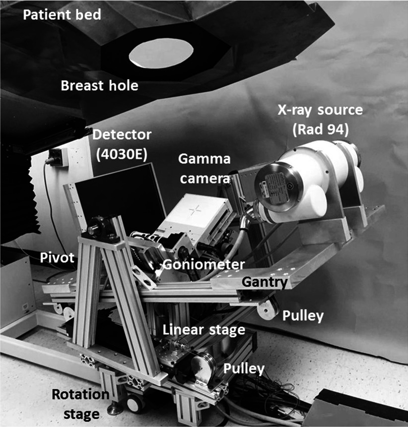
The initial design of a fully 3-D tilt capable breast SPECT–CT imaging system was detailed in our earlier work.44 A refined version of the system (Fig. 1) consists of a tungsten anode x-ray source (Rad 94, Varian Medical Systems) with a 14-deg anode angle, a source to image distance (SID) of 80 cm, and a custom digital flat panel CsI detector (model Paxscan 4030E, Varian Medical Systems, Palo Alto, California), with 8-mm bezel edges on two sides for closer to chest wall imaging.47 The x-ray source and detector are placed on opposing views on a gantry constructed out of 80/20 erector bars and aluminum plates. The weight of the gantry is supported by heavy duty 1-in.-diameter bearings (McMaster-Carr, Elmhurst, Illinois) mounted on pivot posts manufactured using 80/20 bars. This configuration suspends the CT gantry, similar to a cradle, and allows tilting of the fixed-displacement source–detector pair about a 3-D center of rotation (COR).
Fig. 1.
Photograph of the third-generation hybrid SPECT–CT system. The various components of the system are indicated on the photograph.
A mechanism using a linear stage (model ILS250CC, Newport Corp., Irvine, California) and pulleys, connected with a fixed length of cable underneath the gantry, was developed to control the tilting motion, which allows polar tilts of up to . Indeed, the system design required careful tensioning to avoid cable backlash. This was done using a standard “turnbuckle” device. The cables were attached to the underside of the gantry, run through the pulleys, and finally attached to the base plate of the linear motor using a turnbuckle. The cable was looped through the opening in the turnbuckle; once attached, the buckle can be turned such that each turn tightens the cable in both directions.
The compact CZT gamma camera (model LumaGEM 3200S™, Gamma Medica Inc., Northridge, California) is attached to a goniometer (model BGM200PE, Newport Corp., Irvine, California) allowing 0 deg to 90 deg polar positioning about a pendant, uncompressed breast. Both subsystems are placed on top of a single azimuthal rotation stage (model RV350CC, Newport Corp., Irvine, California) and move in unison 360 deg azimuthally, with the SPECT subsystem capable of moving in a complete solid angle hemisphere, and the CT subsystem in a nearly band on a sphere.
Individual parts were manufactured at the Duke University Medical Center Instrument Shop, and the device was assembled in our lab. Additional details of the system components are provided in Table 1.
Table 1.
Technical specifications of individual components comprising the fully 3-D tilt capable SPECT–CT system.
| Component | Technical specifications |
|---|---|
| X-ray source | Varian Rad 94 |
| 14-deg W anode angle | |
| 65 kVp max | |
| 0.4/0.8-mm focal spot | |
| 0.51-mm Ce filtration | |
| FPD | Varian 4030E (Custom) |
| CsI(Tl) TFT array | |
| pixelation | |
| area | |
| 8-mm bezel edges on two sides | |
| Gamma camera | Gamma Medica LumaGem 3200-S |
| array of CZT modules | |
| 2.5-mm CZT pixelation | |
| area | |
| Pb parallel hole collimator | |
| 1.2-mm hex-hole with 0.2-mm septa | |
| Sensitivity— | |
| Rotation stage (azimuthal) | Newport RV350CC |
| 0 deg to 720 deg total rotation | |
| 0.1-deg minimal increment | |
| Linear stage (polar CT) | Newport ILS250CC |
| to 125 mm total displacement | |
| minimal increment | |
| Goniometer (polar SPECT) | Newport BGM200PE |
| 0 deg to 90 deg total arc | |
| 0.1-deg minimal increment |
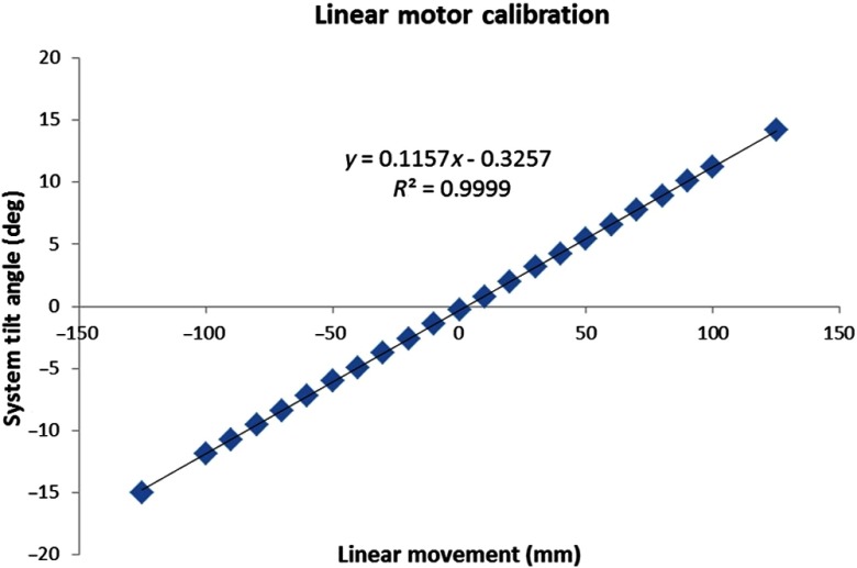
Before initiating experiments, the linear stage was calibrated to determine a relation between the degree of tilt and linear displacement. The linear stage has a motion range of (total 250 mm); the linear displacement in both directions was incremented in 10.0 mm steps ( to 125 as well as 125 to ); and the corresponding polar tilt angle of the system was measured with a digital level (model Pro3600, Flexbar Machine Corp.). The linear displacement was plotted against the measured tilt angle, and the plot was fitted with a linear function; the relation is later used by the CT acquisition software to generate position coordinates in the complex orbits. Measurements were repeated four times, twice in each direction, to measure any hysteresis in the polar tilt angle of the system.
2.2. Experimental Measurements
For preliminary evaluation of the effect of tilted trajectories on object sampling, various phantoms were scanned with a number of trajectories incorporating varying degrees of polar tilt. First, a 10-cm-inner-diameter cylindrical phantom containing (1) four Defrise disks in the top half (model ECT/MI-DEF/P Data Spectrum Corp., Durham, North Carolina) and (2) the rod module from the “Jaszczak” resolution rod phantom was used (model ECT/STD/I, Data Spectrum Corp., Durham, North Carolina). The disks are made of 0.50-cm-thick acrylic with 0.50-cm spacing between each disk; the rod phantom consists of 1.1- to 4.7-mm-diameter acrylic rods spaced on twice their diameter. The cylindrical phantom was positioned in the center of the detector FOV, and 240 projection images were acquired in binning mode. Six different orbits (Fig. 2) were used to investigate the effect of polar tilt on sampling and reconstructed image quality: simple circular azimuthal orbit with (1) no polar tilt (AZOR0) on the system; (2) with the system at a fixed tilt (AZOR3), similar to the fixed tilt of the previous generation SPECT–CT system in our lab;48 and (3) with the system at a fixed tilt (AZOR13), such that the top plane of the x-ray cone beam is approximately horizontal. This last condition (3) is similar to others’ systems with a horizontal upper-most beam,25,49,50 except that our detector is also tilted by 13 deg. More complex 3-D trajectories consisted of (4) two-lobed orbit with sharp transitions at the peak and valley, with maximum polar tilts of (sawtooth); (5) two-lobed sinusoidal (saddle) orbit with maximum polar tilts of ; and (6) three-lobed sinusoidal orbit (3Lobed) traversing through three peaks and valleys with maximum polar tilts of . Note that positive polar tilts are oriented such that the x-ray source is higher than the detector.
Fig. 2.
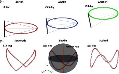
Plots depicting the six different acquisition trajectories utilized for the initial experiments; (a, L-R) Simple circular orbits AZOR0, AZOR3, AZOR13, and (b, L-R) complex acquisition orbits sawtooth, saddle, and 3Lobed. The complex orbits traverse the polar and azimuthal arcs on a sphere (depicted in the saddle plot), about the dotted rotation axis. A graphic representation of the x-ray cone beam and the FPD is also shown at top to better visualize the system tilts for the simple circular orbits.
The combined disk and resolution rod phantom have a total height of 10 cm [Fig. 3(a)], and scanning it while centered in the FOV did not adequately compare the performance of various orbits near the top and bottom of the detector, where the incident cone beam has maximally diverging x-rays and therefore be most prone to cone beam sampling artifacts. Subsequently, a longer Defrise-like phantom consisting of 10 square slabs, 0.5 cm each and spaced 1 cm apart [Fig. 3(b)], was suspended from the patient bed such that the first slab was positioned close to the top of the untilted flat panel detector (FPD). The extended Defrise-like phantom was 17 cm in height. The phantom was scanned with the six acquisition trajectories and the same acquisition parameters listed above. Finally, an additional analysis of the performance of tilted acquisition orbits close to the bottom edge of the detector was performed using a cylindrical phantom consisting of both rods (low scatter) and tubes (drilled in acrylic, thus, high scatter) of identical size and distribution but different media. The combined phantom was suspended such that the resolution rods were oriented perpendicular to the azimuthal rotation axis [Fig. 3(c)]. The phantom was scanned with the AZOR13 and saddle orbits, with the same acquisition parameters as mentioned above.
Fig. 3.
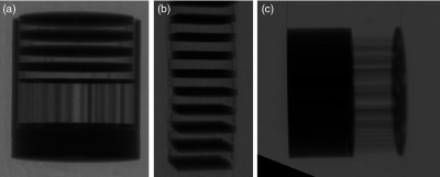
Example zoomed and cropped x-ray projection images of the vertical rotation-axis aligned (a) combined minirod and mini-Defrise phantom, (b) extended Defrise-like slab phantom, and (c) orthogonally oriented to the rotation axis minirod and minitube phantoms. A shadow of the SPECT camera is visible as the triangle in the lower left corner of the right-most projection image.
All raw projection images acquired under the various conditions were then processed through a MATLAB®-based algorithm to apply offset, gain, and defective pixel corrections. The SPECT gamma camera and parts of the goniometer are visible in the FOV near the bottom of the image [Fig. 3(c)]; the amount of image occluded by the camera varies depending on the polar tilt of the system. The area obstructed by the gamma camera was cropped out of each projection image, and the images were reconstructed using an ordered subsets convex (OSC) iterative algorithm.51 Reconstruction parameters were set to 5 iterations, 16 subsets, 0.254 mm voxels, and grid size for all acquisitions and phantoms.
3. Results
3.1. Hardware Implementation
The designed system was successfully constructed, and Fig. 4 shows photographs of the system with the CT gantry at different polar tilts. The radio-opaque patient bed used on the older generation SPECT–CT system has been previously reported in Refs. 52 and 53 and was used for this device as well. Although the linear stage allows CT polar tilt angles of up to , when the patient bed is positioned similar to the positioning during clinical trials, the CT system is limited to a maximum polar tilt of .
Fig. 4.
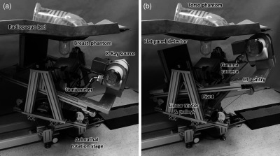
Photographs of the newly developed SPECT–CT system with a torso and breast phantom placed on the radio-opaque patient bed, with the CT subsystem at (a) and (b) polar tilt. Other components are labeled accordingly.
The linear motion calibration results showed that the polar tilt angles measured multiple times at linear increments were within variability. The error bars from repeated measurements are too small to be visualized with the data points. The plot of linear position against polar tilt angle is shown in Fig. 5, and the linear fit to the data points is
| (1) |
where is the polar tilt angle of the CT subsystem and is the displacement of the linear stage in mm.
Fig. 5.
Calibration plot of linear movement versus polar tilt angle of the system. The error in tilt angle was less than 0.02 deg for four measurements, and error bars are smaller than the data points.
System use over 12 months has not indicated any change in the tension of the cables. The error in polar tilt angle at 12 months continued to be .
3.2. Experimental Measurements
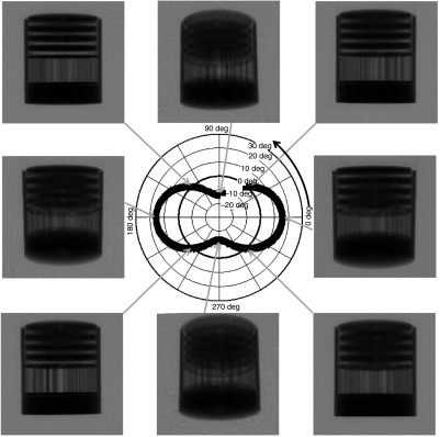
Experiments were successfully performed with the three phantoms and six acquisition orbits detailed in Sec. 2.2. Figure 6 shows representative projection images of the combined disk and rod phantom, at different CT polar tilts, during an acquisition with the saddle trajectory. The various projection images highlight the different views of the phantom that can be obtained by tilting the source–detector pair.
Fig. 6.
Cropped projection images of a Defrise disk + rod phantom, acquired using a saddle orbit, at the azimuthal angular positions indicated on the polar plot. Note that the SPECT gamma camera can be seen in the FOV at the lower left corner and has been cropped out of the projection images for better visualization of the phantom.
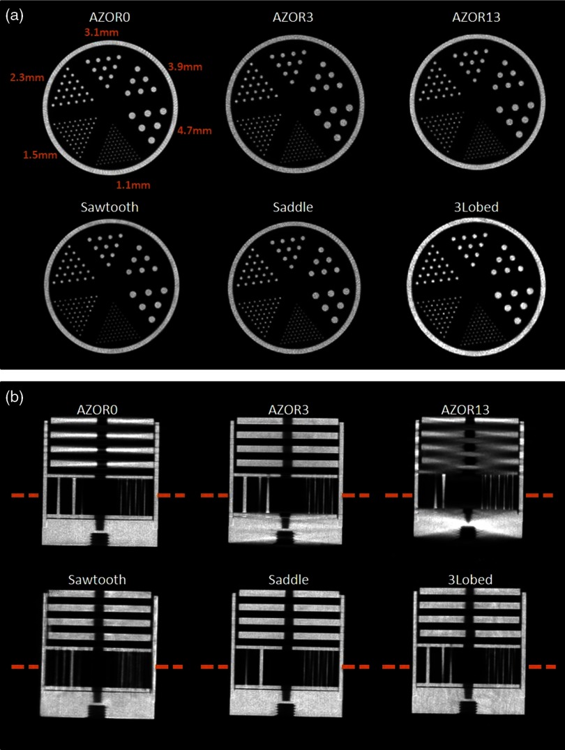
The projection images were reconstructed, and representative slices through the center of the reconstructed phantom volumes are shown in Fig. 7. Coronal slices through the reconstructed volume show excellent resolution performance of the system regardless of the acquisition trajectory. For all three utilized orbits, the smallest 1.1-mm-diameter rods are resolved almost identically to each other. However, sagittal slices reveal the sampling shortcomings of the simple circular AZOR orbits.
Fig. 7.
(a) Coronal slices at the same slice number, locations indicated in (b) of the reconstructed section of the rod phantom, for the indicated acquisition trajectories. Coronal slices show similar image quality. Coronal slice orientation is specified with respect to the breast and body habitus of the scanner system. All images are depicted with the same window/level settings. (b) Sagittal slices (at the same slice number in the reconstructed image) of the Defrise + rod phantom, for the indicated acquisition trajectories. Sagittal slices clearly show the absence of cone beam sampling artifacts in the complex acquisition trajectory images. Sagittal slice orientation is specified with respect to the breast and body habitus of the scanner system. The same window/level settings were used for all six images, and some rods appear missing due to the location of the slice with respect to the phantom center.
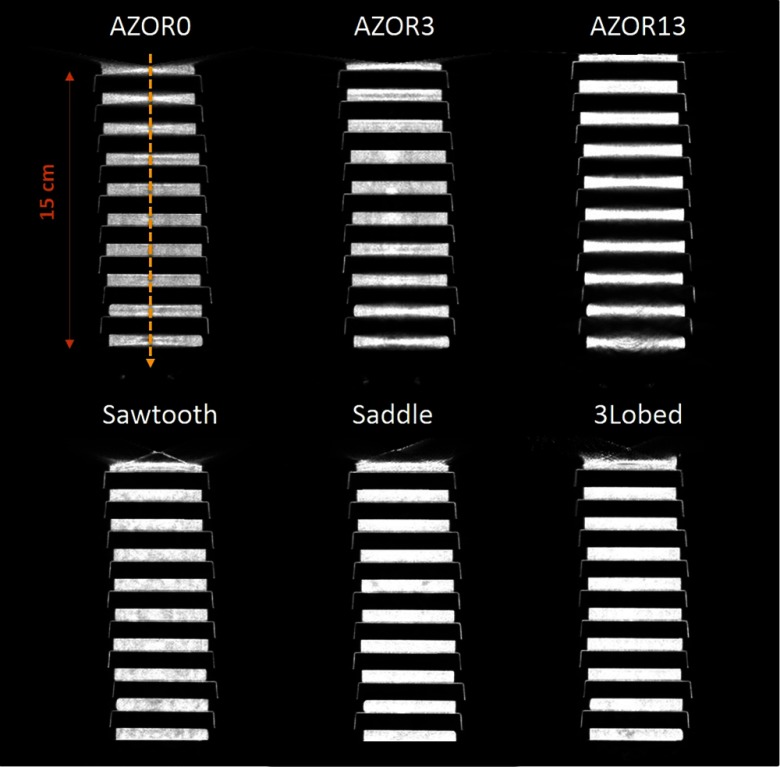
Cone beam sampling artifacts are evident on the AZOR sagittal slices, especially near the sharp edges of the cylindrical phantom, as well as from the blurring of the Defrise disks and threaded hole at the bottom of the phantom due to insufficient sampling. Note that the phantom was centered in the detector FOV, and, therefore, the AZOR3 provides the best sampling and AZOR13 the worst. On the other hand, the complex orbits completely eliminate cone beam sampling artifacts: the Defrise disks show no blurring, the uniform spacing between alternate disks is maintained in the reconstructed images, and the high-frequency threads at the phantom’s bottom are easily recovered. The lack of distortion and overall better sampling in reconstructed images is consistent, regardless of the complex trajectory used.
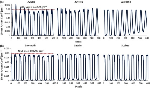
The extended Defrise-like slab phantom rendered results (Fig. 8) similar to the smaller version. The phantom was oriented close to the top of the untilted FPD to evaluate sampling close to what would clinically be the chest wall, as well as near the bottom of the detector that would clinically be the nipple area. Sagittal slices through the reconstructed volume show that for the simple circular orbits, depending on the polar tilt of the system due to the fixed tilt throughout the scan, the Defrise slabs are not adequately sampled. Blurring of the top disks is visible for AZOR0 images, and substantial blurring of the bottom disks can be observed for the AZOR13 images. Although the blurring is visible in images, the amount of blurring can be better appreciated from the profiles measured across the center of the sagittal slices (Fig. 9), where peaks and valleys can be seen on the AZOR0 and AZOR13 profiles instead of a more uniform expected rectangular function. For the complex orbits, the reconstruction of the Defrise-like disks is more uniform, with no intradisk blurring or cone beam sampling artifacts or any other distortions. For all three complex orbits, all 10 Defrise disks (100%) were reconstructed without any blurring, whereas for the circular orbits, 4 to 6 (40% to 60%) of the disks appear blurred, depending on the orbit used. This corresponds to a reduction in the usable FOV of 44% to 63%. Interestingly, the top most disk of the phantom, where the chest wall is expected to be, is also more visible than in the simple circular orbits (Fig. 8).
Fig. 8.
Central sagittal slices of the reconstructed extended Defrise-like slab phantom, for the indicated acquisition trajectories. Blurring and image distortion can be observed in the images obtained with the simple circular orbits, whereas these artifacts are not visible on the complex acquisitions (see also Fig. 9). The same window/level settings were used for all six images (see Fig. 9 for the absolute scale).
Fig. 9.
Profiles measured across the center of the reconstructed sagittal slices of the extended Defrise slabs, for the indicated acquisition trajectories. The OSC algorithm reconstructs data to raw attenuation coefficients; the dotted line represents the attenuation coefficient of acrylic (at 36 keV) obtained from NIST. Profiles indicate that the attenuation coefficients are more uniform and without intradisk blurring for the (a) complex orbits as compared with the (b) simple circular orbits.
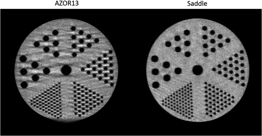
Lastly, the combined rod and tube phantom reconstructions were qualitatively analyzed for image distortions. The combined phantom was oriented orthogonally to the axis of rotation, and, therefore, sagittal slices allow visualization of the rods. Figure 10 shows the comparative sagittal slices of the AZOR13 and saddle reconstructions; the AZOR13 image is clearly distorted near the upper and lower edges. Cone beam sampling artifacts can be seen near the edges of all the rods, and the outer circumference of the cylindrical enclosure of the rods itself looks distorted. Conversely, the saddle reconstruction maintains the integrity of the phantom shape as well as the smallest sized rods, providing a much cleaner, distortion-free image. There were no visible artifacts in the rod-only section of the phantom, partly due to the considerably lower scatter in that region.
Fig. 10.
Sagittal slices through the tube section of the combined rod and tube phantom, for the indicated acquisition trajectories. Note the streaking throughout the AZOR13 phantom, along with blurring tangent to the very top and bottom of the image. The only difference between these acquired data is the simple circular versus complex 3-D acquisitions. The rods could easily be seen in the low scatter rod portion for both trajectories. The same window/level settings were used for both images.
4. Discussion
The hybrid, fully 3-D tilt capable human SPECT–CT imaging system is unique, where both the SPECT and CT subsystems can independently perform complex acquisitions with the target object in a common FOV. Although a stand-alone BCT system capable of polar tilting has been previously developed by us,32 the mechanical designs of those systems are considerably different from the system described in this work. Additionally, the previous tilt capable systems were stand-alone systems, not providing any metabolic or physiological information (although contrast imaging should be possible). A modulation transfer function (MTF) and sampling studies were performed in the past using tilted trajectories.54 X-ray scatter,55 dose distribution,56 and Hounsfield unit (HU) accuracy57 of tilted trajectories have also been investigated on stand-alone devices, but none of these studies have been performed after the inclusion of the SPECT system in the hybrid device. The SPECT subsystem remained unchanged from previous versions of the system and has been evaluated by our group extensively;40,42,58,59 therefore, these measurements were not repeated.
Practical development of the fully 3-D tilt capable system resulted in a few changes from the proposed designs.44 One major change was the use of a Rad94 source with a smaller emission angle (14 deg), which increased the SID to 80 cm; whereas the original designs incorporated a Rad70D source with a 16-deg anode angle that would require a 70-cm SID. Also, the Rad70D source requires liquid cooling from a heat exchanger, which was designed to be placed behind the FPD to balance the weight on the two ends of the CT gantry. In the absence of the heat exchanger, lead weights were placed behind the FPD to balance the Rad94 source and the extended SID. Second, the practical implementation incorporated two pulleys on each side of the linear motor, in place of the single pulley design, to allow system tilts of up to .
One caveat of the current implementation of the SPECT–CT system is the acquisition time. The time taken for a complete CT scan with simple circular orbits, in a step-and-shoot fashion, was 4 min. However, due to a limitation of the Newport motion controller used on this system, wherein only one motor can be addressed at any given time, the step-and-shoot acquisition for complex orbits involved movement of the azimuthal as well as the linear motor for each projection image. This resulted in a slower acquisition time of 8 to 12 min depending on the complex orbit utilized and the degree of polar tilt incorporated into the orbit. Faster acquisition times are possible by increasing the speed of the motors; however, this introduces vibration in the CT gantry that could result in motion artifacts, in addition to any motion of the patient. This phenomenon occurs since the entire CT gantry is suspended from two pivot points in a cradle (Figs. 1 and 4); when the rotational and tilt motions occur at high speeds, the inertia in the gantry causes the system to jiggle, which repeats with every projection step. The vibration is also amplified due to a larger SID, as the source–detector weights are distributed farther away from the COR of the system. Transitioning to the newer Rad70D source with a larger anode angle would result in a smaller SID at full field illumination, thus reducing system vibration. Upgrading the motion controller would allow movement of multiple motors simultaneously, thereby reducing overall acquisition times. Optimization of the current CT acquisition code, programmed in C++, may also allow reduction in scan times. Continuous motion should be investigated with the pulsed source for smoother acquisitions, especially since the CT system now has two different degrees of motion. Such a system will allow for acquisition times of less than 1 min; additionally, the lack of constant acceleration/deceleration will reduce or eliminate the vibration described above, providing greater mechanical stability.
Dose distribution studies previously reported by our group56 indicated that there is no significant difference between dose delivered by simple circular and complex orbits. Scatter studies60 have shown that the scatter-to-primary ratio is dependent on the polar tilt angle of the BCT system. Additionally, complex trajectories have also shown better HU uniformity57 in preliminary studies, which can also be seen in Fig. 9. There is no reason to think that the doses with this system would be any different than those from our previous systems since the source has not changed. However, the better sampling due to additional views close to the chest wall and nipple (Fig. 8) regions, provided by complex trajectories, makes it particularly advantageous for breast imaging. Preliminary results obtained from this newly developed system highlight the superior sampling performance of various complex trajectories and indicate that more complete sampling yields consistently better image quality regardless of the complex trajectory used. Other groups have developed BCT systems that traverse simple orbits similar to the AZOR13,25,49 with the top plane of the cone beam parallel to the top of the detector, in an effort to achieve better sampling near the chest wall. We mimicked that geometry with the AZOR13 trajectory, with one difference: our FPD was also tilted 13 deg. This fixed tilt yields cone beam sampling artifacts near the bottom of the detector since the x-ray cone beam divergence increases as one moves from the top of the imaging FOV to the bottom, as seen in Fig. 10. For those systems with a nontilted detector, there is additional amplification of the sampling artifact beyond even what we measured due to insufficient sampling there. For smaller sized breasts, this tilting would work adequately; however, as the size of the breast volume imaged using the system increases, the amount of sampling artifacts near the nipple region and image distortion would increase. Some studies28,45,46 have indicated that the maximum breast diameters clinically observed range from 18.1 to 20.5 cm and the maximum height from chest wall to nipple ranges from 15.2 to 19.1 cm. For these larger breasts, which span the entire FOV from top to bottom, complex trajectories are highly beneficial compared with the traditional source–detector positioning like in the AZOR13.
The effect of better sampling and elimination of cone beam artifacts would likely improve contrast resolution, which is important for breast imaging. A qualitative assessment of the reconstructed images (Figs. 7 and 10) illustrates that the contrast resolution and noise characteristics of the different tilted trajectories appear similar; moreover, a marked improvement was observed over simple circular (AZOR) orbits. Additionally, due to the more complete sampling coupled with the iterative OSC algorithm used for these studies, the noise characteristics of images obtained using various tilted trajectories is likely to remain comparable. Better sampling also allows better attenuation value recovery. Transmission values play an important role in attenuation correction for SPECT. We expect that the more accurate, artifact-free images would improve SPECT quantitation; however, this work only focuses on the development of the new system and preliminary CT results. Future studies on this hybrid system will include investigation of improvement in SPECT quantitation, the effect of cross-talk between the SPECT gamma camera and the CT FPD, noise characteristics, and detailed sampling studies using anthropomorphic breast phantoms including fine structures close to the chest wall.
Cone beam sampling artifacts have been one of the major hindrances of CBCT, in various applications. Various techniques have been investigated to mitigate these artifacts, by means of software corrections61 as well as clever system designs, such as using multiple sources to achieve better sampling62 and even vertical helical scanning with narrower detectors.63 Tilting the source–detector pair about the target object is a practical method for achieving more complete sampling in one revolution, without requiring additional software corrections. Additionally, complex acquisition trajectories show promise for other CBCT applications beyond breast imaging, particularly for organ or object-specific imaging tasks.
5. Conclusions
A first of its kind, a hybrid SPECT–CT breast imaging device with each individual subsystem possessing the capability to perform fully 3-D arbitrary acquisition trajectories was designed and successfully developed. Several phantom studies highlighted the significantly better performance of fully 3-D acquisition trajectories. The results emphasize the potential of tilt capable imaging systems for BCT, and other possible imaging applications. Complex acquisitions eliminated reconstruction artifacts due to better sampling, thereby improving image quality throughout the imaging volume; simply put, better collected data yield better and more accurately reconstructed BCT images without postreconstruction image processing or data manipulation. The dual-modality imaging system developed in this work would provide more complete sampling of the target volume and improved anterior chest wall access for pendant breast imaging. In addition, this system allows the acquisition of physiological (functional) and anatomical information in a common FOV. The SPECT acquisition would be expected to provide higher specificity data, while the BCT images would provide a roadmap for the SPECT signals, along with high sensitivity, low dose breast imaging. The BCT system could also be used as a stand-alone diagnostic device. The more completely sampled, fully 3-D reconstructed images provided by the system can be used for accurate localization, identification, and even quantification of breast tumors. This unique system shows promise for use as a diagnostic device, in chemo- and radiation therapeutic monitoring, and potentially in screening (such as in high risk populations) as well.
Acknowledgments
The authors would like to thank Don Pearce at the DUMC Instrument Shop for his assistance with machining and refining parts. This work was funded by the National Cancer Institute of the National Institutes of Health (R01-CA096821), and Tornai is also supported by the Duke Department of Radiology. Shah was supported by the Jo Rae Wright Fellowship from Duke BME and NIH T32-EB001040.
Biographies
Jainil P. Shah received his MS and PhD degrees in biomedical engineering from Duke University in 2011 and 2015, respectively. He is currently the lead scientist at Civatech Oncology, where he heads the R&D and Engineering Departments. His current research interests include breast imaging, development of innovative medical devices, and brachytherapy for prostate, gynecological, and head and neck cancers.
Steve D. Mann is a radiation physicist at Duke University. He earned his PhD in medical physics from Duke University in 2014. His graduate school research interests focused on dedicated breast SPECT–CT, with particular interest in the improved accuracy of absolute quantification of Tc-99m Sestamibi uptake in breast tissue. His current interests include development of fluoroscopy and nuclear medicine image quality metrology.
Randolph L. McKinley received his MS degree in electrical engineering from Columbia, and earned his PhD in biomedical engineering from Duke. He is a senior scientist at the Innovision Imaging Laboratory, Inc., Research Triangle Park, where he has been since leaving Zumatek, Inc.
Martin P. Tornai obtained his PhD in biomedical physics from UCLA. He is an associate professor of radiology, biomedical engineering, and a faculty member of the Medical Physics Graduate Program at Duke University. His research interests include investigation and development of dedicated nuclear and x-ray-based breast imaging devices, with which several dozen women have been scanned. He is active on national committees, is entrepreneurial, and enjoys the collaboration and creativity with his graduate students and colleagues.
Disclosures
The authors have no relevant conflicts of interest to disclose.
References
- 1.Kerlikowske K., et al. , “Efficacy of screening mammography: a meta-analysis,” JAMA 273, 149–154 (1995). 10.1001/jama.1995.03520260071035 [DOI] [PubMed] [Google Scholar]
- 2.Pisano E. D., et al. , “Diagnostic performance of digital versus film mammography for breast-cancer screening,” N. Engl. J. Med. 353, 1773–1783 (2005). 10.1056/NEJMoa052911 [DOI] [PubMed] [Google Scholar]
- 3.Kerlikowske K., et al. , “Continuing screening mammography in women aged 70 to 79 years: impact on life expectancy and cost-effectiveness,” JAMA 282, 2156–2163 (1999). 10.1001/jama.282.22.2156 [DOI] [PubMed] [Google Scholar]
- 4.Kolb T. M., Lichy J., Newhouse J. H., “Comparison of the performance of screening mammography, physical examination, and breast US and evaluation of factors that influence them: an analysis of 27,825 patient evaluations 1,” Radiology 225, 165–175 (2002). 10.1148/radiol.2251011667 [DOI] [PubMed] [Google Scholar]
- 5.Baines C. J., To T., Wall C., “Women’s attitudes to screening after participation in the national breast screening study. A questionnaire survey,” Cancer 65, 1663–1669 (1990). 10.1002/(ISSN)1097-0142 [DOI] [PubMed] [Google Scholar]
- 6.Elmore J. G., et al. , “Screening for breast cancer,” JAMA 293, 1245–1256 (2005). 10.1001/jama.293.10.1245 [DOI] [PMC free article] [PubMed] [Google Scholar]
- 7.Boyd N. F., et al. , “Mammographic density and the risk and detection of breast cancer,” N. Engl. J. Med. 356, 227–236 (2007). 10.1056/NEJMoa062790 [DOI] [PubMed] [Google Scholar]
- 8.Michaelson J. S., et al. , “Predicting the survival of patients with breast carcinoma using tumor size,” Cancer 95, 713–723 (2002). 10.1002/(ISSN)1097-0142 [DOI] [PubMed] [Google Scholar]
- 9.Reintgen D., et al. , “The anatomy of missed breast cancers,” Surg. Oncol. 2, 65–75 (1993). 10.1016/0960-7404(93)90046-2 [DOI] [PubMed] [Google Scholar]
- 10.Bird R. E., Wallace T. W., Yankaskas B. C., “Analysis of cancers missed at screening mammography,” Radiology 184, 613–617 (1992). 10.1148/radiology.184.3.1509041 [DOI] [PubMed] [Google Scholar]
- 11.Sechopoulos I., et al. , “Radiation dosimetry in digital breast tomosynthesis: report of AAPM tomosynthesis subcommittee task group 223,” Med. Phys. 41, 091501 (2014). 10.1118/1.4892600 [DOI] [PubMed] [Google Scholar]
- 12.Niklason L. T., et al. , “Digital tomosynthesis in breast imaging,” Radiology 205, 399–406 (1997). 10.1148/radiology.205.2.9356620 [DOI] [PubMed] [Google Scholar]
- 13.Niklason L. T., et al. , “Digital breast tomosynthesis: potentially a new method for breast cancer screening,” in Digital Mammography, Karssemeijer N., et al., Eds., pp. 51–56, Springer, Dordrecht: (1998). 10.1007/978-94-011-5318-8 [DOI] [Google Scholar]
- 14.Gur D., et al. , “Digital breast tomosynthesis: observer performance study,” Am. J. Roentgenol. 193, 586–591 (2009). 10.2214/AJR.08.2031 [DOI] [PubMed] [Google Scholar]
- 15.Poplack S. P., et al. , “Digital breast tomosynthesis: initial experience in 98 women with abnormal digital screening mammography,” Am. J. Roentgenol. 189, 616–623 (2007). 10.2214/AJR.07.2231 [DOI] [PubMed] [Google Scholar]
- 16.Gennaro G., et al. , “Digital breast tomosynthesis versus digital mammography: a clinical performance study,” Eur. Radiol. 20, 1545–1553 (2010). 10.1007/s00330-009-1699-5 [DOI] [PubMed] [Google Scholar]
- 17.Noroozian M., et al. , “Digital breast tomosynthesis is comparable to mammographic spot views for mass characterization,” Radiology 262, 61–68 (2012). 10.1148/radiol.11101763 [DOI] [PMC free article] [PubMed] [Google Scholar]
- 18.Sechopoulos I., et al. , “Computation of the glandular radiation dose in digital tomosynthesis of the breast,” Med. Phys. 34, 221–232 (2007). 10.1118/1.2400836 [DOI] [PMC free article] [PubMed] [Google Scholar]
- 19.Feng S. S. J., Sechopoulos I., “Clinical digital breast tomosynthesis system: dosimetric characterization,” Radiology 263, 35–42 (2012). 10.1148/radiol.11111789 [DOI] [PMC free article] [PubMed] [Google Scholar]
- 20.Park J. M., et al. , “Breast tomosynthesis: present considerations and future applications,” Radiographics 27, S231–S240 (2007). 10.1148/rg.27si075511 [DOI] [PubMed] [Google Scholar]
- 21.Teertstra H. J., et al. , “Breast tomosynthesis in clinical practice: initial results,” Eur. Radiol. 20, 16–24 (2010). 10.1007/s00330-009-1523-2 [DOI] [PubMed] [Google Scholar]
- 22.Andersson I., et al. , “Breast tomosynthesis and digital mammography: a comparison of breast cancer visibility and BIRADS classification in a population of cancers with subtle mammographic findings,” Eur. Radiol. 18, 2817–2825 (2008). 10.1007/s00330-008-1076-9 [DOI] [PubMed] [Google Scholar]
- 23.Boone J. M., et al. , “Dedicated breast CT: radiation dose and image quality evaluation 1,” Radiology 221, 657–667 (2001). 10.1148/radiol.2213010334 [DOI] [PubMed] [Google Scholar]
- 24.Chen B., Ning R., “Cone-beam volume CT breast imaging: feasibility study,” Med. Phys. 29, 755–770 (2002). 10.1118/1.1461843 [DOI] [PubMed] [Google Scholar]
- 25.Glick S. J., “Breast CT,” Ann. Rev. Biomed. Eng. 9, 501–526 (2007). 10.1146/annurev.bioeng.9.060906.151924 [DOI] [PubMed] [Google Scholar]
- 26.Madhav P., “Development and optimization of a dedicated dual-modality SPECT–CT system for improved breast lesion diagnosis,” PhD Thesis, Biomedical Engineering, Duke University; (2010). [Google Scholar]
- 27.Sechopoulos I., “X-ray scatter correction method for dedicated breast computed tomography,” Med. Phys. 39, 2896–2903 (2012). 10.1118/1.4711749 [DOI] [PMC free article] [PubMed] [Google Scholar]
- 28.Vedantham S., et al. , “Dedicated breast CT: fibroglandular volume measurements in a diagnostic population,” Med. Phys. 39, 7317–7328 (2012). 10.1118/1.4765050 [DOI] [PMC free article] [PubMed] [Google Scholar]
- 29.Bowen S. L., et al. , “Initial characterization of a dedicated breast PET/CT scanner during human imaging,” J. Nucl. Med. 50, 1401–1408 (2009). 10.2967/jnumed.109.064428 [DOI] [PMC free article] [PubMed] [Google Scholar]
- 30.Ravindranath B., et al. , “A simultaneous PET/MRI breast scanner based on the RatCAP,” in IEEE Nuclear Science Symp. Conf. Record, pp. 4650–4655 (2008). 10.1109/NSSMIC.2008.4774460 [DOI] [Google Scholar]
- 31.Long Z., Swanson T., O’Connor M., “WE-AB-204-10: evaluation of a novel dedicated breast PET system (Mammi-PET),” Med. Phys. 42, 3661–3661 (2015). 10.1118/1.4925886 [DOI] [Google Scholar]
- 32.McKinley R. L., et al. , “Development and initial demonstration of a low-dose dedicated fully 3D breast CT system,” in Breast Imaging, Maidment A. D. A., Bakic P. R., Gavenonis S., Eds., pp. 442–449, Springer, Berlin: (2012). [Google Scholar]
- 33.O’Connell A., et al. , “Cone-beam CT for breast imaging: radiation dose, breast coverage, and image quality,” Am. J. Roentgenol. 195, 496–509 (2010). 10.2214/AJR.08.1017 [DOI] [PubMed] [Google Scholar]
- 34.Lindfors K. K., et al. , “Dedicated breast CT: initial clinical experience 1,” Radiology 246, 725–733 (2008). 10.1148/radiol.2463070410 [DOI] [PMC free article] [PubMed] [Google Scholar]
- 35.Yang W. T., et al. , “Dedicated cone-beam breast CT: feasibility study with surgical mastectomy specimens,” Am. J. Roentgenol. 189, 1312–1315 (2007). 10.2214/AJR.07.2403 [DOI] [PMC free article] [PubMed] [Google Scholar]
- 36.Mettivier G., et al. , “Dedicated scanner for laboratory investigations on cone-beam CT/SPECT imaging of the breast,” Nucl. Instrum. Methods Phys. Res. Sect. A 629, 350–356 (2011). 10.1016/j.nima.2010.10.093 [DOI] [Google Scholar]
- 37.Wu Y., et al. , “PET characteristics of a dedicated breast PET/CT scanner prototype,” Phys. Med. Biol. 54, 4273–4287 (2009). 10.1088/0031-9155/54/13/020 [DOI] [PMC free article] [PubMed] [Google Scholar]
- 38.Ferrero A., et al. , “Preliminary performance characterization of DbPET2.1, a PET scanner dedicated to the imaging of the breast and extremities,” Biomed. Phys. Eng. Express 1, 015202 (2015). 10.1088/2057-1976/1/1/015202 [DOI] [PMC free article] [PubMed] [Google Scholar]
- 39.McKinley R. L., “Development and characterization of a dedicated computed mammotomography system,” Doctoral Dissertation, Duke University; (2006). [Google Scholar]
- 40.Tornai M. P., et al. , “Design and development of a fully 3D dedicated x-ray computed mammotomography system,” Proc. SPIE 5745, 189 (2005). 10.1117/12.595636 [DOI] [Google Scholar]
- 41.McKinley R. L., et al. , “Investigation of cone-beam acquisitions implemented using a novel dedicated mammotomography system with unique arbitrary orbit capability (Honorable Mention Poster Award),” Proc. SPIE 5745, 609 (2005). 10.1117/12.596089 [DOI] [Google Scholar]
- 42.Mann S. D., et al. , “Initial in vivo quantification of Tc-99m sestamibi uptake as a function of tissue type in healthy breasts using dedicated breast SPECT–CT,” J. Oncol. 2012(8), 146943 (2012). 10.1155/2012/146943 [DOI] [PMC free article] [PubMed] [Google Scholar]
- 43.Shah J., Mann S., Tornai M., “SU-E-l-01: investigating the dependence of 2D and 3D scatter-to-primary ratios on breast density in clinical breast CT,” Med. Phys. 39, 3624–3625 (2012). 10.1118/1.4734715 [DOI] [PubMed] [Google Scholar]
- 44.Shah J. P., et al. , “Design of a nested SPECT–CT system with fully suspended CT sub-system for dedicated breast imaging,” Proc. SPIE 9033, 90335O (2014). 10.1117/12.2043739 [DOI] [Google Scholar]
- 45.Neal A., et al. , “Correlation of breast dose heterogeneity with breast size using 3D CT planning and dose-volume histograms,” Radiother. Oncol. 34, 210–218 (1995). 10.1016/0167-8140(95)01521-H [DOI] [PubMed] [Google Scholar]
- 46.Cutler S. J., Crotty D. J., Tornai M. P., “Dynamic laser-guided contouring for dedicated emission mammotomography,” in IEEE Nuclear Science Symp. Conf. Record, pp. 4789–4793 (2008). 10.1109/NSSMIC.2008.4774314 [DOI] [Google Scholar]
- 47.Shah J., et al. , “MTF characterization in 2D and 3D for a high resolution, large field of view flat panel imager for cone beam CT,” Proc. SPIE 9033, 90333V (2014). 10.1117/12.2043727 [DOI] [Google Scholar]
- 48.Madhav P., et al. , “Initial development of a dual-modality SPECT–CT system for dedicated mammotomography,” in IEEE Nuclear Science Symp. Conf. Record, pp. 2382–2386 (2006). 10.1109/NSSMIC.2006.354392 [DOI] [Google Scholar]
- 49.Gazi P. M., et al. , “Evolution of spatial resolution in breast CT at UC Davis,” Med. Phys. 42, 1973–1981 (2015). 10.1118/1.4915079 [DOI] [PMC free article] [PubMed] [Google Scholar]
- 50.Ning R., et al. , “Evaluation of flat panel detector cone beam CT breast imaging with different sizes of breast phantoms,” Proc. SPIE 5745, 626 (2005). 10.1117/12.596127 [DOI] [Google Scholar]
- 51.Kamphuis C., Beekman F. J., “Accelerated iterative transmission CT reconstruction using an ordered subsets convex algorithm,” IEEE Trans. Med. Imaging 17, 1101–1105 (1998). 10.1109/42.746730 [DOI] [PubMed] [Google Scholar]
- 52.Perez K. L., et al. , “Analysis of patient bed positioning in SPECT–CT imaging for dedicated mammotomography,” Proc. SPIE 6510, 651037 (2007). 10.1117/12.713822 [DOI] [Google Scholar]
- 53.Crotty D. J., et al. , “Investigating novel patient bed designs for use in a hybrid dual modality dedicated 3D breast imaging system,” Proc. SPIE 6510, 65101H (2007). 10.1117/12.713764 [DOI] [Google Scholar]
- 54.Madhav P., et al. , “A novel method to characterize the MTF in 3D for computed mammotomography,” Proc. SPIE 6142, 61421Y (2006). 10.1117/12.653393 [DOI] [Google Scholar]
- 55.Shah J., et al. , “Detailed characterization of 2D and 3D scatter-to-primary ratios of various breast geometries using a dedicated CT mammotomography system,” Proc. SPIE 7961, 796158 (2007). 10.1117/12.878809 [DOI] [PMC free article] [PubMed] [Google Scholar]
- 56.Shah J. P., et al. , “Three dimensional dose distribution comparison of simple and complex acquisition trajectories in dedicated breast CT,” Med. Phys. 42, 4497–4510 (2015). 10.1118/1.4923169 [DOI] [PMC free article] [PubMed] [Google Scholar]
- 57.Shah J. P., “Investigation and development of a fully 3D tilt capable hybrid SPECT–CT system for dedicated breast imaging,” PhD Thesis, Biomedical Engineering, Duke University; (2015). [Google Scholar]
- 58.Perez K. L., et al. , “Towards quantification of functional breast images using dedicated SPECT with non-traditional acquisition trajectories,” IEEE Trans. Nucl. Sci. 58, 2219–2225 (2011). 10.1109/TNS.2011.2165223 [DOI] [PMC free article] [PubMed] [Google Scholar]
- 59.Cutler S., et al. , “Comparison of 2D scintimammography and 3D dedicated breast SPECT using a compressible breast phantom and lesions of varying size and tracer uptake,” in IEEE Nuclear Science Symp. Conf. Record, pp. 5640–5646 (2008). 10.1109/NSSMIC.2008.4774523 [DOI] [Google Scholar]
- 60.Shah J. P., et al. , “Comparison of the effect of simple and complex acquisition trajectories on the 2D SPR and 3D voxelized differences for dedicated breast CT imaging,” Proc. SPIE 9033, 90332L (2014). 10.1117/12.2043764 [DOI] [Google Scholar]
- 61.Hsieh J., “A practical cone beam artifact correction algorithm,” in IEEE Nuclear Science Symp. Conf. Record, Vol. 2, pp. 15/71–15/74 (2000). 10.1109/NSSMIC.2000.950053 [DOI] [Google Scholar]
- 62.Zbijewski W., et al. , “Dual-energy imaging of bone marrow edema on a dedicated multi-source cone-beam CT system for the extremities,” Proc. SPIE 9412, 94120V (2015). 10.1117/12.2082304 [DOI] [PMC free article] [PubMed] [Google Scholar]
- 63.Kalender W. A., et al. , “High-resolution spiral CT of the breast at very low dose: concept and feasibility considerations,” Eur. Radiol. 22, 1–8 (2012). 10.1007/s00330-011-2169-4 [DOI] [PubMed] [Google Scholar]


