Abstract
Purpose
Prisms used for field expansion are limited by the optical scotoma at a prism apex. For a patient with two functioning eyes, fitting prisms unilaterally allows the other eye to compensate for the scotoma. A monocular patient’s field loss cannot be expanded with a conventional or Fresnel prism due to the apical scotoma. A newly invented optical device, the multiplexing prism (MxP), was developed to overcome the apical scotoma limitation in monocular field expansion.
Methods
A Fresnel–prism-like device with alternating prism and flat elements superimposes the shifted and see-through views, thus creating the (monocular) visual confusion required for field expansion and eliminating the apical scotoma. Several implementations are demonstrated and preliminarily evaluated for different monocular conditions with visual field loss. The field expansion of the MxP is compared with the effect of conventional prisms using calculated perimetry and measured visual field.
Results
Field expansion without apical scotoma is shown to be effective for monocular patients with hemianopia or constricted peripheral field. The MxPs are shown to increase the nasal field for a patient with only one eye and for patients with bitemporal hemianopia. MxPs placed at the far temporal field are shown to expand the normal visual field. The ability to control the contrast ratio between the two images is verified.
Conclusions
A novel optical device is demonstrated to have the potential for field expansion technology in a variety of conditions. The devices may be inexpensive and can be constructed in a cosmetically acceptable format.
Keywords: visual field loss, vision rehabilitation, hemianopia, retinitis pigmentosa, multiplexing, prism shift, see-through
Loss of visual field affects the ability to move safely and effectively through the environment. Patients with diseases such as retinitis pigmentosa, choroideremia, and advanced glaucoma experience a concentric shrinking of their visual fields, and patients with hemianopia lose half of the vision on the same side of each eye due to post-chiasmal stroke, injury or tumor. We refer to the former as peripheral field loss and the latter as hemianopic field loss. When prisms are prescribed for the rehabilitation of visual field loss, the aim is to provide better access to the portions of the visual scene that are unseen due to the disease. That access can be important for mobility, both for safety, giving warning of impending hazards and possible collisions, and for orientation, finding one’s way and searching for objects or landmarks. Prisms fitted bilaterally so that they provide the same view to both eyes (yoked prisms) do not provide true field expansion (a larger field of view area at a given gaze position), but rather only provide field substitution (shifting one portion of the scene into view at the expense of another, with no increase of total area viewed). Prisms block a portion of the field of view at their apex, which is about equal in magnitude to the field shifted into view (the apical scotoma, as described in Apfelbaum et al.1 Introduction). The view lost to the apical scotomas may be equal to or of greater importance for safe mobility than the shifted view provided by the prisms.
We distinguish field of view (the portions of the scene that fall on functioning retina) from visual field (the functional portions of the retinas). Prisms cannot expand the visual field, but they can truly expand field of view in some configurations, and that is our focus here. True field expansion can be achieved by superimposing views of the visual scene from the unseen and the seen portions of the field of view. This superimposition results in visual confusion, seeing two different things in the same apparent direction (as illustrated in Fig. 1 of Apfelbaum & Peli2 Introduction).
If a patient has two functional eyes, it is possible to fit the prisms in front of just one eye. In such fittings, the visual field of each eye includes a different portion of the field of view, thus providing true field expansion through visual confusion.1 People can generally tolerate visual confusion in their peripheral field (where it is a natural consequence of binocular vision),3 but it is disturbing when in the central field. Further, binocular visual confusion can lead to rivalry and suppression, potentially limiting the field-expansion benefits. With suppression, one view disappears from the percept, while with rivalry the views alternate, resulting in disappearance of one of the views at a time.4–6 If a patient has only one functional eye (monocular), unilateral fitting of a conventional prism cannot be used to produce the visual confusion necessary for field of view expansion. However, our new invention, the multiplexing prism can provide a solution. In this preliminary report, we describe the multiplexing prism, its construction, applications, and measurements. We then show how several field loss conditions can be treated with various configurations of the multiplexing prism, and address the corresponding advantages and limitations.
METHODS
The Multiplexing Prism
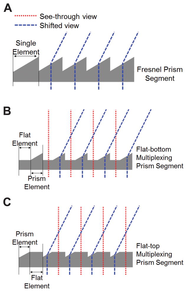
Conventional Fresnel prisms have an array of identical prismatic elements linearly arranged base to apex (Fig. 1A). multiplexing prisms have prismatic elements alternating with flat elements in a single segment (Figs. 1B & C). When placed in front of the eye, the shifted view and the see-through view are seen simultaneously through the prism and the flat elements, respectively. Total field of view is expanded with no field lost to an apical scotoma. However, the two views are superimposed, and both are seen at lower contrast.
Figure 1.
Multiplexing prisms (MxP). (A) Schematic profile of a conventional Fresnel prism segment showing the light deviating towards the base in each element. Profile of a multiplexing prism segment alternating the flat and prism elements in (B) flat-bottom type and (C) flat-top type. The prism elements deflect rays and shift the view via prismatic effect (blue dashed lines), while the see-through view passes through the flat elements (red dotted lines). The user can see multiplexed (superimposed) see-through and shifted views.
The visual confusion experienced with the multiplexing prism is monocular (within one eye), which is not readily susceptible to suppression or rivalry. Monocular rivalry is a much rarer effect than binocular rivalry,7–12 and it likely occurs only with extended attention. Such attention is not likely when using peripheral prisms that fit the prism in the upper and lower central periphery.13 Thus, the multiplexing prism has the potential for reduced rivalry and suppression in binocular patients. Most importantly, it is the only apical-scotoma-free field expansion option for monocular patients. multiplexing prisms can be designed as flat-bottom (Fig. 1B) or flat-top (Fig. 1C), or both. They can be molded with high optical quality and at low cost (per piece).
We have obtained a few samples of the type shown in Fig. 1B, manufactured by molding for another purpose (Jenoptic Polymer Systems, Rochester, NY), for preliminary measurements (Fig. 2A). Note that these molded prisms have a small flat top section in addition to the wider flat bottom section. multiplexing prism prototypes for the configuration shown in Fig. 1C were produced (by Chadwick Optical, Souderton, PA) by grinding and polishing flat surfaces onto conventional PMMA Fresnel prism blanks. The techniques they developed achieve accurate and consistent results, as illustrated in Fig. 2B.
Figure 2.
Prototypes of the multiplexing prisms. (A) Micrograph of a molded mostly flat-bottom type prototype (with small flat top elements as well) 40Δ MxP with equal aperture ratio (B) Micrograph of 57Δ flat-top type MxP with equal aperture ratio manufactured by grinding and polishing a Fresnel prism.
Multiplexing Prism Functionality
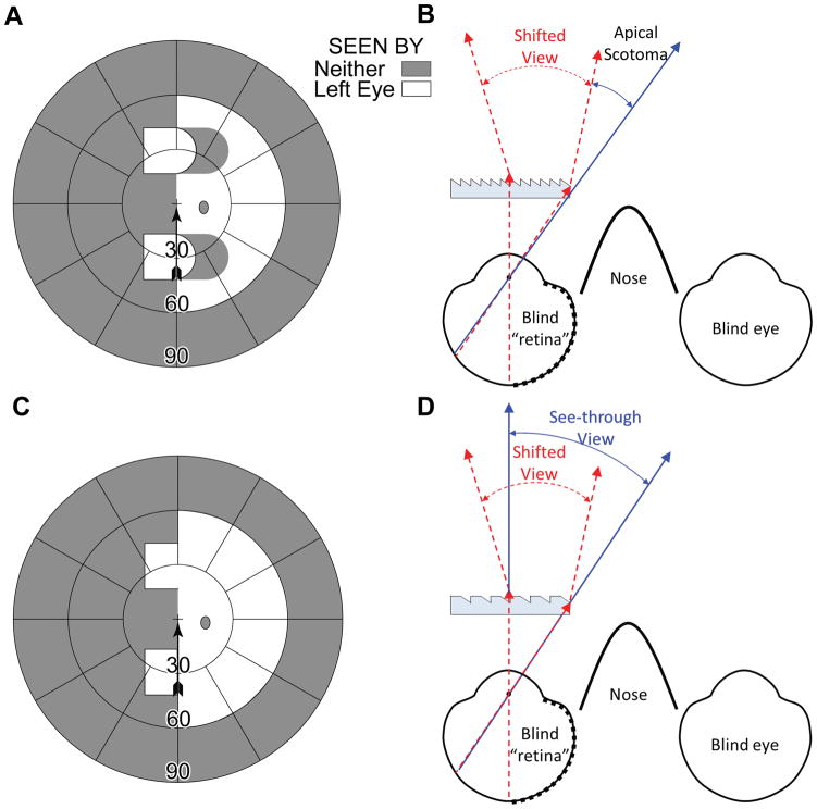
The main advantage of the multiplexing prism as a field expansion device is the elimination of the apical scotoma. Apfelbaum et al.1 discussed advantages and limitations of various prism designs for hemianopic field loss and pointed out the impact of apical scotomas in many of the designs. In the most commonly used approach, where the prisms are fitted unilaterally for a binocular patient with homonymous hemianopia, the corresponding visual field in the other eye compensates for the apical scotomas that affect the eye with the prisms. If a patient with hemianopic field loss is monocular, peripheral prisms13 fitted to provide a view from the blind hemifield are affected by the apical scotomas and, therefore, only provide field substitution, not field of view expansion (Figs. 3A & B). However, as shown in Figs. 3C & D, the multiplexing prism flat elements restore the view otherwise lost to the apical scotomas, providing true field of view expansion.
Figure 3.
Multiplexing prism glasses for a monocular patient (left eye only) with left hemianopic field loss. (A) Calculated Goldmann perimetry diagram for the primary gaze field of view of the patient fitted with upper and lower base-left 30Δ horizontal peripheral prisms. The expanded view into the left blind hemifield comes with the loss of right side view due to the apical scotomas. (B) Ray diagram (viewed from above) for the configuration shown in (A), illustrating the shifted view and source of the apical scotomas. (C) Calculated Goldmann perimetry diagram of the same monocular patient when MxPs are used. There is true field expansion with no field lost to apical scotomas. (D) The corresponding ray diagram shows shifted (red dashed lines) and see-through (blue solid lines) views falling on the same retinal area with visual confusion.
For convenience here and elsewhere, we ray trace through the prism as if the rays were emerging from the eye rather than from the object of regard.14, 15 This is particularly useful in the case of hemianopia, as one can start from the foveal line of sight that represents the most extreme ray that will fall on the functioning side of the retina after deflection by the prism.15 Due to the reversibility of optics, the actual rays entering the prism from the object of regard follow the same paths.
Calculated and Measured Perimetry
The effect of the prisms in various field expansion applications, specifically the effects of apical scotomas and their elimination with the multiplexing prism, are demonstrated in this paper using calculated perimetry diagrams are and verified with measurements. Calculated perimetry diagrams are scaled in degrees of visual angle (from the nodal point). We assume a cornea to nodal point distance of 7.1mm (per Gullstrand’s Schematic Eye16) and spectacles with a back vertex distance of 13mm.
When possible, we used a PC-based perimeter17 to illustrate field expansion and apical scotomas with and without multiplexing prisms. To avoid false detections of the target in spurious reflections,14 in this perimetry, we can use dark targets on a bright background. The target size was 0.8° (about target size IV in Goldmann perimetry). Because the PC-based perimeter measures only up to 80º of field of view, we used a Goldmann perimeter with a V4e target for wider field measurements.
Subjects with peripheral field loss and hemianopic field loss were selected for their convenient availability. Their perimetric results were used to verify our calculated perimetry. Apfelbaum and Peli2 have pointed out that failures to conduct such verification resulted in incorrect assertions of field expansion effects in a number of prior publications. The prism prescriptions used here were not necessarily optimized for the subjects’ particular needs (in term of prism powers or contrast ratio), so these should not be considered clinical case studies.
The Multiplexing Effect in Different Prism Configurations
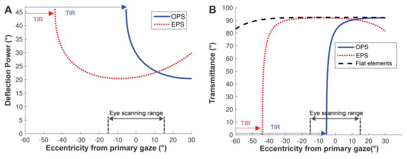
The high power multiplexing prisms (more than 40Δ, desired for most field-expansion applications) result in the same prism deflection power and transmittance variations as a function of the angle of incidence that affect conventional or Fresnel prisms.14 As the angle of incidence is increased toward the base side, the prism power is increased (causing wider field of view expansion with distortion/minification) until it is blocked by total internal reflection beyond the critical angle of incidence. We define the critical angle of incidence (Eq. 4 in Jung & Peli22) as the angle of incidence at the eyeward surface of the prism that first results in total internal reflection (critical angle) at the second surface of the prism. As shown in Fig. 4, both the deflection power and transmittance in the prism elements vary with the eccentricity from primary gaze (and thus angle of incidence) and by prism configuration: outward prism serrations and eyeward prism serrations.14 In both configurations, the optical transmittance and the prism deflection power variations trade off with each other and affect the usable eye scanning range and the contrast of the scene.
Figure 4.
Variation of deflection power (in degrees) and transmittance of the prism elements in 57Δ PMMA MxP (39° apex angle with n = 1.49).14 A negative sign indicates an angle toward the base side of the prism. (A) The prism deflection power (proportional to field of view expansion) varies with the angle of incidence much more in the outward prism serrations (OPS) configuration. Due to total internal reflection (blue dotted arrows), the OPS prism cannot deflect light beyond the −5.3° critical angle of incidence. In the eyeward prism serrations (EPS) configuration, the angle of incidence is reduced, which reduces the prism deflection power. However, the reduction avoids total internal reflection and provides more constant prism power over the practical eye scanning range (±15°). total internal reflection is eventually encountered at about −44° (red dotted arrows). (B) The transmittance in the flat elements of the MxP is constant at 92% (and starts to drop at about 50° eccentricity) and the EPS prism elements have almost the same transmittance within the practical eye scanning range. In both configurations, the transmittance varies with the angle of incidence and reduces sharply when approaching the critical angle of incidence, which in the OPS configuration is well within the eye scanning range, while in the EPS configuration it is at the far limit of eye scanning.
In the eyeward prism serrations multiplexing prism configuration, the prism elements maintain relatively constant power and optical transmittance (almost as high transmittance as in the flat elements) over a wide and practical eye scanning range eccentricities (about ±15°)18 and total internal reflection starts at farther eccentricity (about 44°), though the prism deflection power is lower than the rated power. In the outward prism serrations multiplexing prism configuration the prism elements have higher deflection power (wider field of view expansion) than the nominal rated power but with lower transmittance, and with limited eye scanning range in the direction of field expansion (about −5.3° in 57Δ prisms) due to total internal reflection.14
Calculated Contrast Attenuation in Multiplexing Prisms
Superimposing the see-through and shifted views in the multiplexing prism causes the contrast of each view to be affected by the other view’s brightness. The local image brightness perceived by the user is not only controlled by the luminance of the scene, which is spatially variable and independent of the device, but is also affected by the prism transmittance and by the aperture ratio.
Dividing the multiplexing prism segment into the prism and flat elements reduces total apertures for each type of element and splits the available luminous flux between them. We define the aperture ratio (r) as the ratio of the area of a prism element to the sum of the prism and the flat element areas. Only r of the total luminous flux will be passed through the prism element and that results in a reduction of the retinal illuminance by a factor of r in the shifted prism view and by (1 − r) in the see-through view. The aperture ratio also affects the contrast of the views.
Where the luminance of the see-through view is about the same as the luminance of the background seen in the shifted view, the contrast reduction factor (CR), the contrast of the target seen through the multiplexing prism over the original contrast of the target, is approximately the same as the aperture ratio (r) of the multiplexing prism (see the Appendix, available at [LWW insert link]).
In addition to the flux attenuation effect (caused by the aperture ratio), the luminance through the prism or flat elements is also affected and reduced by the optical transmittance of each element. The flat elements always have fixed (and high) transmittance regardless of the angle of incidence (Fig. 4B), whereas the optical transmittance of the prism elements varies with the angle of incidence14 and is mostly lower than the optical transmittance of the flat elements. Therefore, the contrast reduction factor of a target in the shifted view is lower than the aperture ratio (r), further reducing the target contrast. If the transmittance in the prism elements is close to that of the flat elements, as in the eyeward prism serrations configuration (Fig. 4B), the contrast reduction is approximately the same as the aperture ratio (CR ≈ r). However, around the critical angle of incidence, the contrast of the shifted view is highly reduced by the much smaller transmittance in the prism elements than the flat elements (see the Appendix, available at [LWW insert link]).
Measuring Contrast Attenuation in Multiplexing Prisms
To measure the contrast reduction factor of the shifted and see-through views with different aperture ratios, we compared the contrast sensitivity of 7 normally-sighted subjects (aged 23 to 35 years) through multiplexing prisms with aperture ratios of 40%, 54%, and 68% to their sensitivity without prisms.
The subjects wore monocular 57Δ multiplexing prism glasses centrally over one eye, with the fellow eye patched. We used the eyeward prism serrations configuration to achieve almost uniform contrast reduction. The subjects’ head was positioned with a chin rest 40 cm from a linearized LCD monitor displaying a mean luminance of 219 cd/m2 as the background. A fixation cross was displayed at the center of the screen, and Gabor (sine phase) patches at different contrast levels were positioned 21° from the screen center (the prism power of an eyeward prism serrations 57Δ prism). The Gabor patches could not be seen through the see-through view (visual field toward base side was limited to 15° by masking tape) and could only be observed in the shifted view. A horizontal Gabor patch (to limit effects of horizontal prism magnification) of 10° diameter at a spatial frequency of 3 cycles/deg was used. Subjects adjusted their head/spectacles position to superimpose the shifted view of the patch over the fixation cross.
Two randomly interleaved 60-trial staircases varied patch contrast with a two-down/one-up rule in each aperture ratio condition. The ratio of a step-down/step-up was 0.5488 (that converges to 80%-correct), as recommended by Garcia-Perez.19 A beep signaled the start of each one-second trial, with the patch randomly displayed in the first or second half-second interval, with another beep to indicate the start of the second interval. The subject provided a two-alternative-forced-choice response by pressing one of two buttons to indicate whether the target was shown during the first or second interval. The condition order was counterbalanced and randomized. Trial data were fitted through maximum likelihood estimation to a Weibull psychometric function to calculate a contrast detection threshold.
All procedures were approved by the Mass. Eye & Ear Human Studies Committee in accordance with the Declaration of Helsinki and all subjects provided informed consent.
RESULTS
Views through High Power Multiplexing Prisms
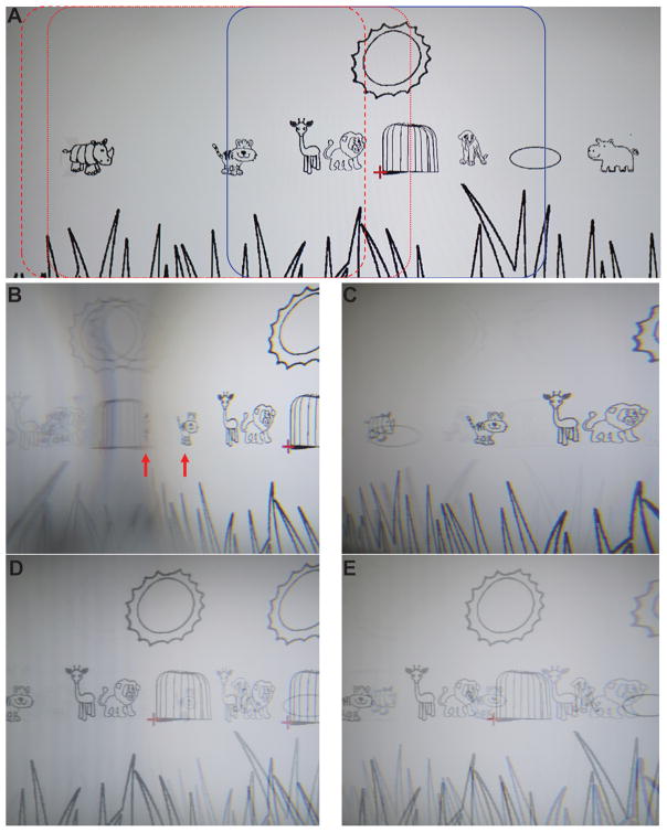
Fig. 5 compares photos taken through the highest power (57Δ) conventional Fresnel prism and multiplexing prism in outward prism serrations and eyeward prism serrations configurations. The photos were taken with the various prisms placed base left 20 mm in front of a nodal point of the 16 mm lens of a Sony α6000 camera, covering the lens fully. These photos represent the views as might be experienced by a monocular subject wearing a full prism of each configuration in front of his functioning eye.
Figure 5.
Photographs of the views through conventional Fresnel and multiplexing prisms with the prism in OPS and EPS configurations (base-left 57Δ flat-top MxP with 50% aperture ratio). The camera exposure and aperture settings were fixed so that the contrast differences can be compared among the various conditions. (A) An image of the savannah cartoon (Fig. 1A in Apfelbaum & Peli2) without the prisms. Blue rectangle indicates the portion of the scene within the see-through view, spanning 48° horizontally. Red dotted and dashed rectangles outline the portion of the scene within the shifted view in the OPS and EPS configurations, respectively. (B) Photo through a conventional OPS Fresnel prism shows a right shifted view with minification (horizontally compressed tiger and highly compressed rhinoceros at the red arrows). Dimming of the shifted view left of the rhinoceros due to total internal reflection results in only the spurious reflections from the right being seen. Note mirror reversal reflections of objects in this area. (C) Conventional EPS Fresnel prism shows less shifted view. The rhinoceros and the tiger in (B) are farther to the right than in (C), with magnification on the right (see the magnified lion) and there is no total internal reflection (within the range seen). Weak spurious reflections are everywhere (but more visible on the left; see the horizontally flipped elliptical pool and grass blades). (D) OPS MxP shows both shifted and see-through views. Note the doubled sun and animals. The contrast of both views is reduced to 50% by the aperture ratio. The transmittance reduction of the shifted view around the area of total internal reflection results in lower contrast (see a much fainter tiger in the cage). In the total internal reflection range, the shifted view is dimmed. As a result, the see-through view is seen with higher contrast (higher contrast lion, giraffe, and tiger). In addition, the spurious reflections in the total internal reflection area are suppressed by the see-through luminance. (E) EPS MxP shows both the shifted and see-through views (doubled animals). On the right (apex side), the slightly reduced transmittance of the shifted view lowers its contrast (lion). In other areas, the contrast is higher and equal in both shifted and see-through views (50% aperture ratio). The spurious reflections across the visual field are low contrast and hardly visible.
The conventional prism images (Figs. 5B & C) show a single shifted view (to the right), with slightly reduced contrast and sharpness due to the color dispersion of the high power prisms. Spurious reflections from the right side are visible in some cases on the left side. The images from the multiplexing prisms show both the shifted and see-through views superimposed and, as expected, at reduced contrast (Figs. 5D & E). Note that in these full-field images, both visual confusion and diplopia (seeing the same object in two different directions) are apparent. As pointed out by Apfelbaum and Peli1 visual confusion is the mechanism for achieving field of view expansion, but diplopia has no useful purpose in this application and it should be avoided. As will be seen in the examples below, avoiding diplopia is possible and practical. If such prisms were applied to a monocular patient with left hemianopic field loss, objects imaged to the left of the center would not be visible to the patient when in primary gaze. Therefore, most of the spurious reflections seen here will not have an effect most of the time.
The images also show the different effects of the two prism configurations.14 With a conventional outward prism serrations prism (Fig. 5B), due to the rapid change in prism power and transmittance with eccentricity to the base side (Fig. 4A), there is strong spatial compression (minification) and contrast reduction of the shifted view. These effects are greater near the critical angle of incidence (just left of the center). Farther left, past the critical angle of incidence, total internal reflection (darker area to the left of the highly compressed rhinoceros) blocks the light from the desired shifted view and thus enables high visibility of multiple spurious reflections (the horizontally flipped sun, cage, and giraffe and the second faint sun and lion, including their background luminance). Due to the tradeoff between prism power and transmittance, the more minified portions of the scene are imaged through lower transmittance.
In the outward prism serrations multiplexing prisms (Fig. 5D), contrast reduction caused by the multiplexing is apparent for both shifted and see-through views (on the right half). In the total internal reflection range (left of the center), the see-through view shows at higher contrast (giraffe and tiger) due to the dark background caused by total internal reflection of the shifted view. Because of the bright see-through background, the contrast of the spurious reflections is reduced and they are not visible (flipped sun, cage, giraffe, and lion in Fig. 6B).
Figure 6.
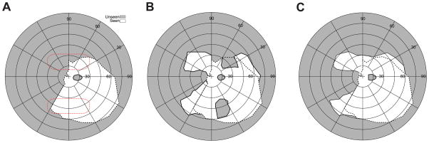
Field expansion for a monocular patient with left (incomplete) hemianopic field loss. (A) Goldmann perimetry without prisms showing a residual field in the lower left quadrant. The red dotted lines indicate the presumed fitting position of the prisms (note the prism position relative to the field varies with head posture). (B) Goldmann perimetry (field of view) with conventional OPS peripheral prisms (57Δ, base left), showing field substitution with apical scotomas. Expansion of the lower field is about the same as the upper field, despite the lower residual field, because of the field of view limitation imposed by total internal reflection (left 5°). (C) With OPS MxPs (57Δ), the apical scotomas are eliminated, providing true field of view expansion. The dashed line on each plot represents the boundary of the seeing field without prisms. The scotoma at the horizontal meridian to the right of the fovea is the patient’s enlarged physiological blind spot.
With conventional eyeward prism serrations prisms (Fig. 5C), the right end of the shifted scene is magnified as the prism power is lower than in the outward prism serrations configuration (narrower field of view expansion) and there is no total internal reflection (within the range shown). The transmittance is a little lower on the apex side (see Fig. 4B) but that effect is too small to be appreciated in the image. Weak spurious reflections (reversed grass blades and elliptical pool) are visible on the left. In the eyeward prism serrations multiplexing prism (Fig. 5E), the shifted and see-through views are multiplexed across the whole scene without total internal reflection. Due to the lower transmittance of the (magnified) shifted view near the apex side, the contrast of the see-through view around the apex side is little higher than in the outward prism serrations configuration (elliptical pool) while the contrast of the shifted view is lower (lion). Across most of the scene, the contrast is quite constant. The spurious reflections are suppressed by the bright see-through view.
Monocular Patient with Hemianopic Field Loss
Fig. 6A shows measured Goldmann perimetry for a monocular patient with incomplete left hemianopic field loss (some residual vision in the lower left quadrant). Conventional peripheral outward prism serrations prisms (57Δ) provide mere field substitution with corresponding apical scotomas (Fig. 6B), as illustrated in Fig. 3A. Note that the apical scotoma width is narrower than the prism power due to the reduced prism power at the apex.14 With outward prism serrations multiplexing prisms (Fig. 6C), there is no loss to apical scotomas. Due to the multiplexing, there is visual confusion (not shown in the figure) of the shifted and see-through views. True monocular field expansion was hitherto impossible with conventional prisms.
Monocular Patient with Peripheral Field Loss
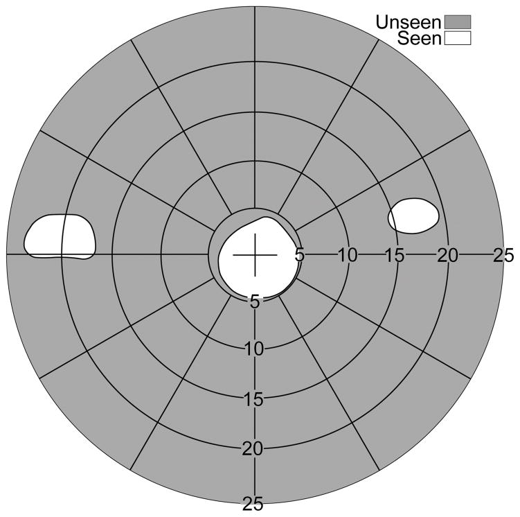
While a person with hemianopic field loss has 50% of the normal visual field remaining, a peripheral field loss patient with 20° of residual central field (qualifying as legally blind in most countries) has only about 1.5% of a normal visual field area, making any interference of a prism with the precious residual field difficult to tolerate. No solution using conventional prisms has met lasting acceptance (as reviewed in Apfelbaum & Peli2). If the peripheral field loss patient has only one functional eye, the apical scotomas associated with conventional prisms are a poor tradeoff for field expansion. The challenges are further complicated by the need for expansion to both the right and left side. Fig. 7 illustrates a possible solution using multiplexing prisms for monocular peripheral field loss patients.
Figure 7.
Field of view expansion glasses (57Δ) for a monocular patient (left eye blind) with severe peripheral field loss. (A) MxP spectacles provide scotoma-free views from the left (base-in upper prism) and right (base-out lower prism) field. For a patient with 20° diameter residual central field, the prisms are separated vertically by 3.5mm (~10° of visual angle), affecting the upper and lower 5° of the residual field. The shifted partial iris and eyelid views (seen in the upper and lower prisms) are superimposed on the eye’s see-through view. Calculated perimetry for (B), the effect of conventional Fresnel prism glasses, and (C), the MxP spectacles shown in (A) with OPS MxPs, illustrates the benefit of MxPs. While the conventional Fresnel prisms just substitute fields due to the apical scotoma (split residual central field), the narrow central field is expanded to both sides by the MxPs. The peripheral islands are wider than the residual field they are imaged upon due to the minification effect in the OPS configuration.
If the vertical prism separation is set to 50% of the residual central field, the width of the residual island taken halfway up the island image (3/4 of the visual field radius from primary gaze) is about 2/3 of the residual field island. The size of the residual island covered by the prism segment is expanded due to the prism distortion effect of the high power prisms used.
The narrow vertical separation between the upper and lower prisms is necessary for the prisms to be even partially in view while at primary gaze.13 However, natural vertical head bobbing while walking can move the prisms in and out of the central view (as the patient’s vestibular system automatically rotates the eyes to maintain a steady gaze) and thus provide intermittent increases in the vertical extent of the expanded field of view section. When the movements bring the fovea into the field of the prism, the see-through views in the multiplexing prisms preserve the important central view with brief central visual confusion.
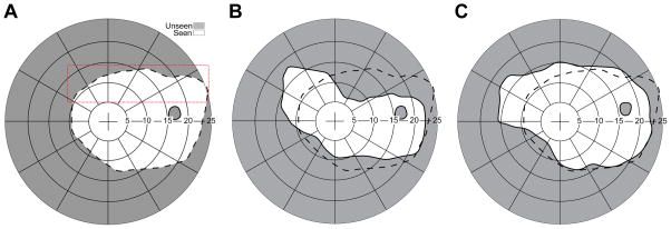
A right eye monocular patient with peripheral field loss due to optic atrophy (Fig. 8A) was tested with a conventional Press-On™ (3M, Minneapolis, MN) peripheral prism (40Δ) in eyeward prism serrations configuration in the upper position (Fig. 8B) and an eyeward prism serrations multiplexing prism 40Δ (as shown in Fig. 2A) in the same position (Fig. 8C). Note that the eyeward prism serrations configuration reduced the nominal prism power from 40Δ to ~32Δ but is necessary to provide expansion at the higher angle of incidence at the lateral left edge of the scotoma. The shifted expanded views to the left in both cases are similar, but the apical scotoma is absent with the multiplexing prism. The magnitude of the expansion is smaller than expected, presumably due to the reduced peripheral sensitivity in this eye with 20/500 visual acuity.
Figure 8.
Field of view expansion of a monocular (right eye) patient with peripheral field loss and poor visual acuity (20/500). (A) PC-based perimetry without the prism. The red dotted outline represents the presumed prism position. The actual prism position varies with head posture. (B) Field of view with an EPS Press-On prism (40Δ). The field is shifted as well as the accompanying apical scotoma. Due to the upper prism position that covers the upper boundary of the visual field, the apical scotoma is connected all the way to the upper boundary of the visual field. (C) With an MxP in EPS, the apical scotoma is eliminated and there is true field expansion, not a just substitution. Black dashed line on each plot represents the boundary of the seeing field without prisms.
Binocular Peripheral Field Loss
Patients with peripheral field loss need to detect hazards from both the left and right sides. As with monocular peripheral field loss, head bobbing can periodically move the prisms into foveal view during walking, but the flat elements of the multiplexing prisms ensure that fixated objects are not completely lost from view, and likely mitigate the effects of the abrupt foveal appearance of the shifted views. With two (partially) functional eyes, more prism configuration options are possible. Further testing is needed (and planned) to determine which design will prove to be most effective and comfortable in terms of binocular rivalry and contrast reduction. Fig. 9 shows binocular perimetry for a patient with severe retinitis pigmentosa and less than 10° of residual central vision. We fitted 40Δ outward prism serrations multiplexing prisms in the horizontal configuration (base out ) in the upper segment on the right lens and in the oblique configuration15 (base out and down) in the upper segment of the left lens. Oblique prisms tilt the base of the prismatic elements, creating vertical as well as lateral prismatic effects, so that the view provided is closer to the horizontal midline, with slight loss of expansion extent.15, 20, 21 However, the efficacy of the oblique configuration in this narrow area of central vision is questionable.
Figure 9.
Binocular perimetry for a patient with severe field loss due to retinitis pigmentosa, wearing upper MxPs 40Δ base out on each carrier lens. There are two expansion areas (seen monocularly) and no apical scotomas. The left eye prism, base left, was tilted obliquely down bringing the expansion area on that side closer to the horizontal midline.
This example also illustrates that the expansion “islands” need not be adjacent to the residual central field. Just where the island should be targeted for optimal hazard detection has been recently investigated, for the case of collision between two pedestrians walking in an open environment, and higher eccentricities up to 45° have been recommended.22 In this example, the prisms provide a view of an area at about 20° eccentricity. Prism powers less than the residual field diameter would cause the island to overlap with the central field and result in diplopia. Due to the fitting of a prism in front of each eye with the bases in opposite lateral directions, the patient experienced both monocular and binocular visual confusion, with both expanded views and the upper central view perceived in the same direction. Other configurations may be preferred in such a case.
Acquired Monocular Vision
After losing vision in one eye (acquired monocular vision, AMV), an otherwise normally-sighted person has only about 55° to 60° of nasal visual field.23 Despite a total remaining field of about 150°, AMV patients do report difficulties with the loss of the temporal field of their blind eye, such as bumping into people alongside them, especially in crowded environments such as school corridors or shopping malls. Duke Federico da Montefeltro (a 15th-century Italian warrior, https://en.wikipedia.org/wiki/Federico_da_Montefeltro) had the bridge of his nose removed surgically after losing the right eye. This drastic treatment approach has limited value as it only overcomes the impact of the nose bridge on the field of view. That field of view expansion is only about 10º in the primary position of gaze, though it may be more meaningful when gazing to the side of the blind eye, of course with similar loss of field on the temporal side of the other eye. Therefore, the large gaze shift also constitutes field substitution rather than expansion.
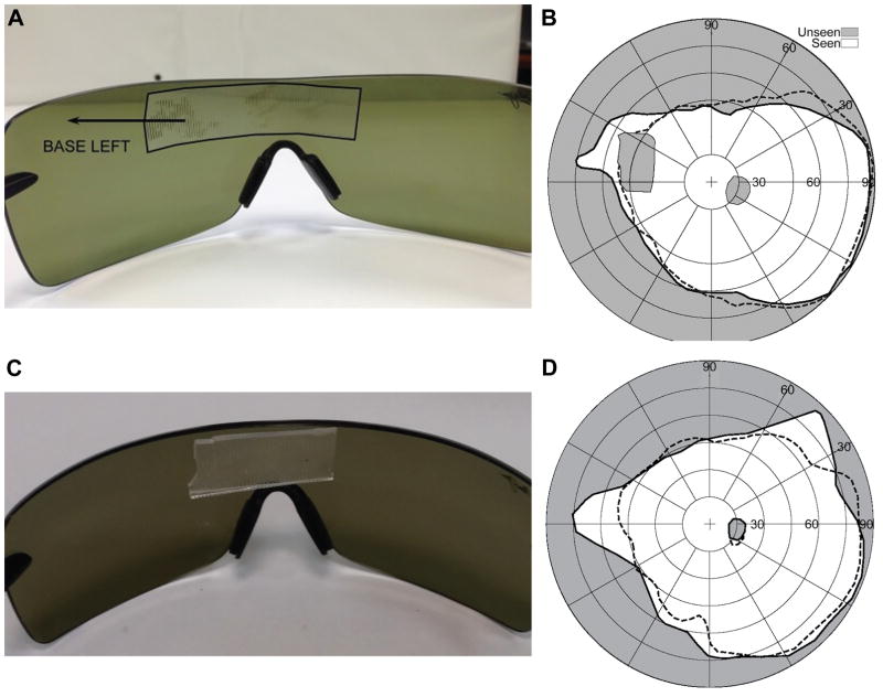
The multiplexing prism offers a way to provide access to portions of the lost field (even in primary gaze) without losing residual field to an apical scotoma. We first attached an multiplexing prism segment inside wraparound sunglasses for field expansion for an AMV patient (Fig. 10). The wide space between the spectacles and the eye in the wraparound sunglasses is suitable to hold the multiplexing prism segment and optimal from a cosmetic point of view. The prism was fitted in front of the nasal field of the functioning eye with base in to expand the field toward the patient’s blind side, as shown in Fig. 10C. Fig. 10D shows expansion of about 15° achieved by placing a 40Δ eyeward prism serrations multiplexing prism base left at the bridge of the sunglasses. The prism was placed in eyeward prism serrations configuration to move the critical angle of incidence to the needed higher eccentricity, as in Fig. 4A. The prism power is reduced in eyeward prism serrations configuration but total internal reflection would be prohibitive with a 57Δ prism, even in eyeward prism serrations configuration.
Figure 10.
MxP glasses for a monocular patient with a blind left eye. (A) Wraparound sunglasses with a 40Δ EPS conventional Press-On prism mounted over the bridge. The left extent of the prism could be much shorter than used here, but is inconsequential as it is in front of the blind eye. (B) Field substitution and an apical scotoma of 20º result with this conventional prism design. The unaided monocular field is shown within the dashed line. (C) Wraparound sunglasses with a 40Δ EPS MxP attached. (D) Field expansion without an apical scotoma is achieved with the prototype MxP in the same position. Lower contrast and visual confusion due to the multiplexing is expected but not shown here. The edges of the prism in (A) were highlighted in black to improve the visibility of the illustration.
Expanding the Normal Temporal Field of View
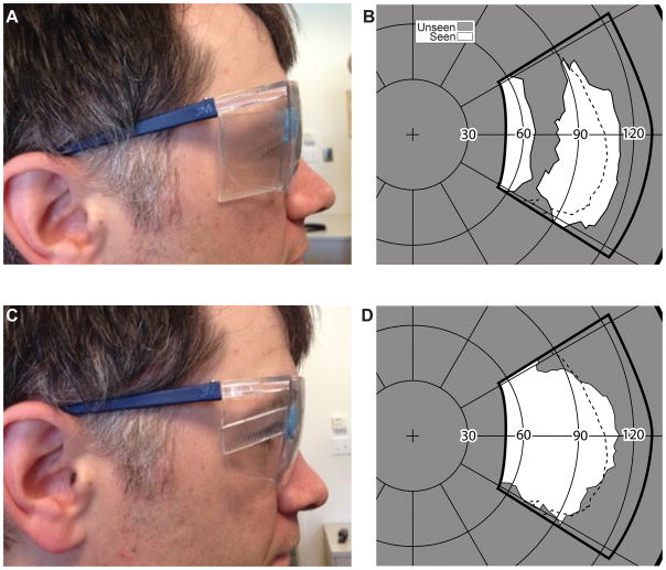
The expansion of the far-temporal periphery of the normal binocular field would be beneficial in many situations such as cyclists in heavy traffic and soldiers in urban warfare. Helmet or spectacles-mounted rear-view mirrors create scotomas and reverse the images, and they cover the space behind the cyclist and not to the temporal sides. A spectacle design incorporating Fresnel lenses (prisms) placed in the far periphery of wraparound spectacles to provide increased peripheral field for bicyclists was proposed on the Internet.24 The actual effect of those spectacles would be field substitution with apical scotoma gaps in the mid-periphery of the fields (Figs. 11A & B). The apical scotoma gap is not illustrated on the web page, presumably because the designer was not aware of the apical scotoma effect.
Figure 11.
Expanding the normal peripheral field. (A) A conventional PMMA 40Δ OPS Fresnel prism mounted base out on the lateral wing of a pair of safety glasses. (B) The field measured with the spectacles shown in (A). The subject was facing and fixating 90º from the center of the perimetry screen. The thick solid line illustrates the area covered by the perimetry screen, as projected on a Goldmann like polar graph. An expansion of about 10° with a corresponding apical scotoma of similar size was measured. The normal field, measured without the prisms, is indicated by the dashed line. (C) A segment of MxP OPS 40Δ is placed at the same position on the spectacles. (D) The field recorded with the MxP shows absence of any apical scotoma. The shorter (vertically) expanded area is due to the narrower prism segment used in this case.
Placing an multiplexing prism in the far periphery of wraparound glasses can expand the temporal field of view without blocking any portion of the view (Figs. 11C & D). To obtain the perimetry measurements the subject was facing approximately 90º and 1 m away from the center of the PC perimeter screen. The deviations from the expected 20° expansion and scotoma sizes are likely measurement errors in the far periphery or due to prism distortion at such wide angles (addressed below). With proper alignment of the prism, expansion of even more than 30° may be expected with a 57Δ nominal prism power.
Contrast Sensitivity Measurement with Various Aperture Ratios
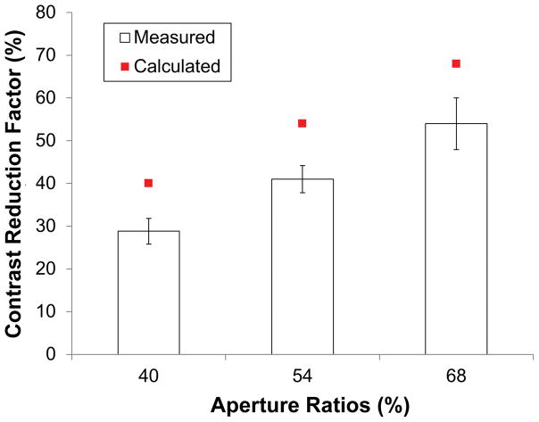
Contrast sensitivity of 7 normally-sighted subjects was measured in 4 conditions: with eyeward prism serrations multiplexing prisms of 40%, 54%, and 68% aperture ratio and without an multiplexing prism. The contrast reduction factor was computed as C/CM where C was the contrast threshold without the multiplexing prism and CM was the threshold with the multiplexing prism. Fig. 12 shows the mean contrast reduction factors for different multiplexing prism aperture ratios based on the measured contrast thresholds. The contrast reduction factor was expected to match the aperture ratio in the eyeward prism serrations multiplexing prism, and the results show that the perceived contrast reduction factor was indeed proportional to the aperture ratio. Therefore, the contrast reduction in the multiplexing prisms can be controlled by the aperture ratio. The lower contrast found in the measurement may be caused by imperfections of the ground and polished prototype samples used. Further testing comparing to a ground and polished flat optical material may resolve this difference.
Figure 12.
Mean measured contrast reduction factors for 40%, 54%, and 68% ratios of EPS MxPs (14% step of aperture ratio among samples) with 7 normal subjects. The measured contrast reduction factors are proportional to the aperture ratio though they are little lower than the calculated reduction factor. Note that each measured factor is 11%, 13%, and 14% smaller than the aperture ratio (40%, 54%, and 68%, respectively). Error bars represent the standard error of the mean.
DISCUSSION
We have developed and characterized a novel optical element, the multiplexing prism. We illustrated its potentially substantial benefits in expanding field of view for patients with various types of field loss as well for applications such as cycling or urban warfare that can benefit from a wider-than-normal field of view. The principal advantage the multiplexing prism offers is overcoming the apical scotoma limitation of conventional prisms. The main applications we envision are for monocular vision such as AMV, monocular hemianopic field loss and peripheral field loss, and even the monocular temporal crescents in the far periphery of normal vision. The monocular confusion from the multiplexing prism is the only way to expand the monocular field of view without an apical scotoma. Secondarily, this allows prisms to be placed closer to the primary line of sight, where they may intersect the foveal views due to eye movements, such as those that occur due to head bobbing when walking. The later effect may be particularly important when fitting the peripheral prisms for patients with binocular tunnel vision. Yet, much work is needed to determine optimal designs, preferred parameters for powers and contrast ratios, followed by real-world tests of efficacy, comfort, cosmetics, and acceptability by users.
The outcome of such research is likely to be affected by the side effects of the multiplexing prism s. While monocular visual confusion is the way the multiplexing prism provides field expansion, it is not clear how acceptable and comfortable it might be. Binocular confusion, especially in the periphery, is a common everyday experience and may be easier to adapt than the monocular confusion. The visual response to monocular visual confusion is not well known, except for the literature we cited about the lower likelihood of monocular rivalry.7–12 In particular the response to peripheral monocular confusion is yet to be determined.
The impact of the lower contrast of images through an multiplexing prism on detection or comfort/confidence also needs to be determined. The reduction of contrast has a positive effect on the reduction of spurious reflections. With conventional outward prism serrations Fresnel prisms most of the spurious reflections fall in the blind field of view,14 and so have little impact. In eyeward prism serrations configurations, the spurious reflections are widely spread over the visual field (Fig. 5). In multiplexing prism, the see-through brighter view masks the dim spurious reflections that may cause false alarms. This may be an important advantage for multiplexing prisms, at least in daylight conditions.
The high contrast Goldmann perimetry does not directly identify the contrast reduction caused by the monocular multiplexing. The perimetry also cannot detect or show the visual confusion associated with the multiplexing. Perimetry can detect diplopia if it exists, but that has to be explicitly tested for and was not included here since we have already shown that it can be avoided with proper designs.1, 14
While we have provided preliminary analyses of the impact of high power prisms on transmittance and magnification, the combined effects of these variables on the ability to detect hazards need to be determined experimentally. Such effects are particularly difficult to analyze in far peripheral vision, where reduced sensitivity and low-resolution sampling interact with the effects of low contrast, minification, and visual confusion. Evaluating the benefit of multiplexing prisms relative to conventional prisms in field of view expansion applications for monocular patients is likely to be challenging, as it requires comparing the impact of the lower contrast and monocular visual confusion with the impact of the apical scotoma, respectively. This difference has to be smaller than the difference between the effect of field expansion design and sham prisms. None of these is easy to measure.25, 26 Yet, determining the preferred designs and parameters for these treatment options is likely to be of value. The prevalence of monocular hemianopic field loss and of monocular peripheral field loss is substantially lower than the corresponding binocular conditions (though the conditions are not rare). This may impede recruitment for such studies. On the other hand, AMV is highly prevalent, which together with the expansion of the far peripheral field for normally-sighted individuals may represent possible future applications of multiplexing prisms.
Peripheral prisms for bilateral homonymous hemianopic field loss are generally fitted unilaterally so that the fellow eye can see the field in the region of the apical scotomas of the prism eye. This solution has been quite successful, with about 50% of patients accepting the prisms in our long-term community-based trials,21, 25 and even higher rates independently reported by others.27 Chadwick Optical has filled over 1,000 prescriptions for these glasses. In addition, many more peripheral prisms have likely been dispensed by practitioners using the less expensive Press-On™ prisms. Nonetheless, the unilateral fitting results in binocular visual confusion, which is susceptible to rivalry and suppression4–6 and may limit effectiveness or acceptance. Having different views in each eye can also be a source of discomfort. If multiplexing prisms are fitted and used bilaterally, an apical-scotoma-free solution is provided with within-eye (monocular) visual confusion rather than binocular rivalry. With no conflict between the eyes, this may be a more comfortable and acceptable solution. On the other hand, monocular confusion and lower contrast may result in suppression in place of the alternating binocular rivalry. Even if there is no binocular rivalry, inattentional blindness may be possible in monocular confusion (as it can exist with binocular confusion), and it, as well as the contrast reduction, may affect detection rates.28 With two (partially) functional eyes, more prism configuration options are possible.29 Further testing is needed to determine which design will prove to be most effective and comfortable.
Acknowledgments
Supported in part by NIH grant R01EY023385. Dr. Peli has a patent application for the Multiplexing Prism and its applications, assigned to the Schepens Eye Research Institute.\
We thank Henry Apfelbaum for help with the manuscript and figures generation, and Amy Doherty and Kassandra Lee for help with subject tests.
APPENDIX
To analyze the contrast reduction in the MxP, we assume that users see the multiplexed scene of a target image, a Gabor patch with maximum (M) and minimum (m) luminance, over a uniform background luminance of (M+ m)/2, in the shifted view. The see-through view is the view of a blank area through the flat elements with uniform luminance B (which may be different from the background of the Gabor patch). The Michelson contrast of the target (C) observed without the MxP is (M − m )/(M +m ).
The luminance of the target in the shifted view is reduced by the factor of the aperture ratio, r. Similarly, the luminance of the blank image seen through the flat elements (BF) is reduced by (1 − r). As a result, the contrast of the target in the multiplexed scene (CM) is
| (1) |
where MP= rM, mP= rm, and BF= (1 − r) B. The contrast of the target seen through the MxP is reduced by CR, the contrast reduction factor,
| (2) |
The contrast reduction factor (CR) is highly affected by the luminance of the see-through view (BF) that in turn is controlled by the uniform background (B) and the aperture ratio (r). If the see-through view is dark (B ≪m), there is little contrast reduction (CR ≈ 1). Similarly, if the aperture ratio is such that the width of the prism elements is much wider than the width of the flat elements (r ≈ 1), as is the case with a conventional prism, the contrast is not reduced. However, a more likely situation is where the luminance of the see-through view is about the same as the luminance of the background seen in the shifted view. In this situation, B ≈ (M + m)/2 and BF= (1 − r)(M + m)/2. Therefore, the contrast reduction factor (CR) is approximately the same as the aperture ratio (r) of the MxP.
In addition to the flux attenuation effect (caused by the aperture ratio, r), the luminance through the prism or flat elements is also affected and reduced by the optical transmittance of each element (tP for the prism elements and tF for the flat elements). The optical transmittance of the prism elements is not a constant but a function of the angle of incidence, as shown in Fig. 4B. When the luminance of the background in the see-through view is the same as the shifted views, the contrast reduction factor (CR) will be modified by the optical transmittance:
| (3) |
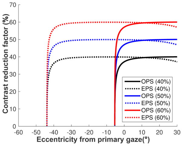
The flat elements always have fixed (and high) transmittance (tF) regardless of the angle of incidence (Fig. 4B), whereas the optical transmittance of the prism elements (tP) varies with the angle of incidence14 and is mostly lower than the optical transmittance of the flat elements (tF). Therefore, the contrast reduction factor of the target in the shifted view may be lower than the aperture ratio(r), further reducing the target contrast. If the transmittance in the prism elements is close to that of the flat elements (tP ≈ tF), as in the EPS configuration (Fig. 4B), the contrast reduction is approximately the same as the aperture ratio (CR ≈ r) as shown in Fig. A1.
To compensate for the contrast reduction caused by the transmittance difference, the aperture ratio should be higher than the desired contrast reduction factor. At normal incidence, for example, the transmittance of a flat element of 57Δ PMMA MxP is 92 % but a 57Δ OPS prism element has only 82% transmittance, which results in 47% of the original contrast with MxP aperture ratio of 50%. An aperture ratio of 53% MxP would result in the intended 50% contrast reduction. This difference is too small to be meaningful. Although an angle of incidence close to the critical angle of incidence results in highly reduced transmittance and contrast, for most of the angular range, the aperture ratio is the main factor in the contras t reduction in the OPS configuration.
If the target/object-of-interest is in the see-through view and the shifted view has a blank image of the same background luminance, the contrast reduction factor of the see-through view is 1 − CR. Due to the optical transmittance reduction in the prism elements (blank background), the contrast of the target in the see-through view is little higher than the aperture ratio.
Figure A1.
Contrast reduction of the target in the shifted view of a 57Δ MxP with various aperture ratios ( r= 40%, 50%, and 60%). Due to the variation of the transmittance in the prism elements and fixed transmittance in the flat elements, the contrast reduction in the MxP is controlled by the transmittance variations in the prism elements. In the EPS configuration, the contrast is almost the same as the aperture ratio, though it drops close to zero near TIR in higher eccentricities. In the OPS configuration, however, the wide variation in transmittance with gaze angle results in highly reduced contrast, especially when approaching the critical angle of incidence.
Footnotes
Contrast reduction of the see-through and shifted views in multiplexing prism is analyzed for different aperture ratios and angles of incidence in the Appendix, available at [LWW insert link]. This contrast reduction is the main side effect of the multiplexing prism and is affected by the two variables analyzed.
References
- 1.Apfelbaum HL, Ross NC, Bowers AB, Peli E. Considering apical scotomas, confusion, and diplopia when prescribing prisms for homonymous hemianopia. Transl Vis Sci Technol. 2013;2:1–18. doi: 10.1167/tvst.2.4.2. [DOI] [PMC free article] [PubMed] [Google Scholar]
- 2.Apfelbaum H, Peli E. Tunnel vision prismatic field expansion: Challenges and requirements. Transl Vis Sci Technol. 2015:4. doi: 10.1167/tvst.4.6.8. [DOI] [PMC free article] [PubMed] [Google Scholar]
- 3.Bishop PO. Binocular vision. In: Moses RA, editor. Adler’s Physiology of the Eye: Clinical Applications. St. Louis: C.V. Mosby; 1981. pp. 575–649. [Google Scholar]
- 4.Ross NC, Bowers AR, Peli E. Peripheral prism glasses: Effects of dominance, suppression, and background. Optom Vis Sci. 2012;89:1343–52. doi: 10.1097/OPX.0b013e3182678d99. [DOI] [PMC free article] [PubMed] [Google Scholar]
- 5.Haun AM, Peli E. Binocular rivalry with peripheral prisms used for hemianopia rehabilitation. Ophthalmic Physiol Opt. 2014;34:573–9. doi: 10.1111/opo.12143. [DOI] [PubMed] [Google Scholar]
- 6.Shen J, Peli E, Bowers AR. Peripheral prism glasses: Effects of moving and stationary backgrounds. Optom Vis Sci. 2015;92:412–20. doi: 10.1097/OPX.0000000000000552. [DOI] [PMC free article] [PubMed] [Google Scholar]
- 7.Campbell FW, Howell ER. Monocular alternation: a method for the investigation of pattern vision. J Physiol (Lond) 1972;225:19P–21P. [PubMed] [Google Scholar]
- 8.Breese BB. On inhibition. Psychol Monogr. 1899;3:i–65. [Google Scholar]
- 9.Crassini B, Broerse J. Monocular rivalry occurs without eye movements. Vision Res. 1981;22:203–4. doi: 10.1016/0042-6989(82)90184-5. [DOI] [PubMed] [Google Scholar]
- 10.Bradley A, Schor C. The role of eye movements and masking in monocular rivalry. Vision Res. 1988;28:1129–37. doi: 10.1016/0042-6989(88)90139-3. [DOI] [PubMed] [Google Scholar]
- 11.Andrews TJ, Purves D. Similarities in normal and binocularly rivalrous viewing. Proc Nat Acad Sci USA. 1997;94:9905–8. doi: 10.1073/pnas.94.18.9905. [DOI] [PMC free article] [PubMed] [Google Scholar]
- 12.Sindermann F, Lüddeke H. Monocular analogues to binocular contour rivalry. Vision Res. 1972;12:763–72. doi: 10.1016/0042-6989(72)90002-8. [DOI] [PubMed] [Google Scholar]
- 13.Peli E. Field expansion for homonymous hemianopia by optically-induced peripheral exotropia. Optom Vis Sci. 2000;77:453–64. doi: 10.1097/00006324-200009000-00006. [DOI] [PubMed] [Google Scholar]
- 14.Jung JH, Peli E. Impact of high power and angle of incidence on prism corrections for visual field loss. Opt Eng. 2014;53:061707. doi: 10.1117/1.OE.53.6.061707. [DOI] [PMC free article] [PubMed] [Google Scholar]
- 15.Peli E, Bowers AR, Keeney K, Jung JH. High-power prismatic devices for oblique peripheral prisms. Optom Vis Sci. 2016;93:521–33. doi: 10.1097/OPX.0000000000000820. [DOI] [PMC free article] [PubMed] [Google Scholar]
- 16.Fannin TE, Grosvenor T. Clinical Optics. 2. Boston: Butterworth-Heinemann; 1996. [Google Scholar]
- 17.Woods RL, Apfelbaum HL, Peli E. DLP-based dichoptic vision test system. J Biomed Optics. 2010;15:1–13. doi: 10.1117/1.3292015. [DOI] [PMC free article] [PubMed] [Google Scholar]
- 18.Luo G, Vargas-Martin F, Peli E. The role of peripheral vision in saccade planning: Learning from people with tunnel vision. J Vis. 2008;8:1–8. doi: 10.1167/8.14.25. [DOI] [PMC free article] [PubMed] [Google Scholar]
- 19.Garcia-Perez M. Forced-choice staircases with fixed step sizes: asymptotic and small-sample properties. Vision Res. 1998;38:1861–81. doi: 10.1016/s0042-6989(97)00340-4. [DOI] [PubMed] [Google Scholar]
- 20.Peli E. Peripheral field expansion device. 7,374,284 B2. United States Patent US. 2008 May 20;
- 21.Bowers A, Keeney K, Peli E. Randomized crossover clinical trial of real and sham peripheral prism glasses for hemianopia. JAMA Ophthalmol. 2014;132:214–22. doi: 10.1001/jamaophthalmol.2013.5636. [DOI] [PMC free article] [PubMed] [Google Scholar]
- 22.Peli E, Apfelbaum H, Berson EL, Goldstein RB. The risk of pedestrian collisions with peripheral visual field loss. J Vis. 2016;16:1–5. doi: 10.1167/16.15.5. [DOI] [PMC free article] [PubMed] [Google Scholar]
- 23.Good GW, Fogt N, Daum KM, Mitchell GL. Dynamic visual fields of one-eyed observers. Optometry. 2005;76:285–92. doi: 10.1016/s1529-1839(05)70311-0. [DOI] [PubMed] [Google Scholar]
- 24.May B. [Accessed: April 10, 2017];Nike Hindsight. http://www.coroflot.com/billymay/Nike-Hindsight.
- 25.Bowers AR, Keeney K, Peli E. Community-based trial of a peripheral prism visual field expansion device for hemianopia. Arch Ophthalmol. 2008;126:657–64. doi: 10.1001/archopht.126.5.657. [DOI] [PMC free article] [PubMed] [Google Scholar]
- 26.Bowers AR, Tant M, Peli E. A pilot evaluation of on-road detection performance by drivers with hemianopia using oblique peripheral prisms. Stroke Res Treat. 2012;2012:1–10. doi: 10.1155/2012/176806. [DOI] [PMC free article] [PubMed] [Google Scholar]
- 27.O’Neill EC, Connell PP, O’Connor JC, Brady J, Reid I, Logan P. Prism therapy and visual rehabilitation in homonymous visual field loss. Optom Vis Sci. 2011;88:263–8. doi: 10.1097/OPX.0b013e318205a3b8. [DOI] [PubMed] [Google Scholar]
- 28.Apfelbaum HL, Apfelbaum DH, Woods RL, Peli E. Inattentional blindness and augmented-vision displays: Effects of cartoon-like filtering and attended scene. Ophthalmic Physiol Opt. 2008;28:204–17. doi: 10.1111/j.1475-1313.2008.00537.x. [DOI] [PMC free article] [PubMed] [Google Scholar]
- 29.Peli E. Vision modification based on a multiplexing prism. PCT/US2014/017351. United States Patent Application. 2014 Aug 28;


