

Abstract
To accurately mimic the native tissue environment, tissue engineered scaffolds often need to have a highly controlled and varied display of three-dimensional (3D) architecture and geometrical cues. Additive manufacturing in tissue engineering has made possible the development of complex scaffolds that mimic the native tissue architectures. As such, architectural details that were previously unattainable or irreproducible can now be incorporated in an ordered and organized approach, further advancing the structural and chemical cues delivered to cells interacting with the scaffold. This control over the environment has given engineers the ability to unlock cellular machinery that is highly dependent upon the intricate heterogeneous environment of native tissue. Recent research into the incorporation of physical and chemical gradients within scaffolds indicates that integrating these features improves the function of a tissue engineered construct. This review covers recent advances on techniques to incorporate gradients into polymer scaffolds through additive manufacturing and evaluate the success of these techniques. As covered here, to best replicate different tissue types, one must be cognizant of the vastly different types of manufacturing techniques available to create these gradient scaffolds. We review the various types of additive manufacturing techniques that can be leveraged to fabricate scaffolds with heterogeneous properties and discuss methods to successfully characterize them.
Keywords: Gradient scaffolds, additive manufacturing, scaffold fabrication, tissue engineering, regenerative medicine
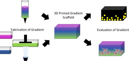
Graphical abstract
1. Introduction
Consideration of a tissue-engineered scaffold’s architecture on the macro-, micro- and nanoscale is crucial for proper nutrient and waste transport, cellular interactions, mechanical stability, and ultimately functional tissue formation [1]. Despite developments in material selection and scaffold design, it can still be difficult to achieve tissue biomimicry in these scaffolds, which significantly affects the resulting tissue regeneration [2]. As observed by Zhang et al., a scaffold carefully designed to mimic the architecture of the extracellular matrix (ECM) of native tissue can be expected to induce and direct cells to develop towards functional tissue [3]. In addition to the importance of material selection, inclusion of proper biochemical or biophysical stimuli could contribute to appropriate development. ECM can have specific spatial arrangement or be haphazardly organized depending on the type of tissue. Specific properties of the scaffold, if made to carefully mimic the native tissue, contribute to functional tissue formation. For example, scaffolds with uniform pore size and porosity similar to that of natural bone can lead to bone tissue formation [4]. Similarly, electrospun scaffolds with areas of poly(lactic-co-glycolic acid) (PLGA) fibers in an aligned or random orientation, designed to mimic collagen type I fibril orientation found in tendons, were created and seeded with fibroblasts [5]. Cells on aligned fibers elongated along the direction of the fibers and produced collagen type 1 in an organized fashion, as seen in native tendon fibroblasts. This approach, biomimicry of a component of the native environment, could be improved as research moves past biomaterial scaffolds with homogenously distributed composition or structural properties [6]. Native tissue often exists as a series of connected and graded transitional zones to build distinct functional regions. The lack of heterogeneity within previous scaffolds does not support the diverse populations of cells and surrounding environment of the native tissue. Thus, it is critical that the engineer incorporates graded properties within scaffolds to properly guide the development of new tissue. The advent of 3D printing and additive manufacturing has enabled the design of tissue scaffolds with precise designs incorporating graded properties that support the heterogeneous population of cells and matrix components that will eventually populate them.
3D printing, also referred to as additive manufacturing, rapid prototyping, or solid-freeform technology, emerged in a few fields in the mid 1980s, and today has found industrial applications in the automotive, aerospace, construction, and even the cosmetic industry [7]. This technology has swept through the commercial world, transforming established practices and disrupting manufacturing techniques much like an industrial revolution, and has contributed to numerous biomedical applications within the research setting [8]. Specifically in the field of tissue engineering, 3D printing has been applied to virtually all tissues in the body and has even been utilized to fabricate whole organs [9].
Before the development of additive manufacturing techniques, tissue engineers used traditional scaffold fabrication techniques such as particulate leaching, electrospinning, phase separation, and gas foaming to achieve architectural variety in fabricated scaffolds [10]. While each of these methods have been extensively studied and optimized, they have inherent limitations. For example, these conventional methods are incapable of precisely controlling pore geometry, interconnectivity, and pore size, and especially of creating regions of variance within a single scaffold [11]. In addition, several of these techniques are contingent upon using organic solvents with inherent biocompatibility [12]. Additive manufacturing techniques allow the tissue engineers to circumvent these limitations through precise control over the design of the scaffold. This results in greater reproducibility, higher level details, and even patient-specific constructs [13].
This review focuses on additive manufacturing techniques that are being used to fabricate polymer-based, gradient scaffolds for tissue engineering. While these technologies are already being used to fabricate homogenous and patient-specific scaffolds, the true utility of these technologies is the level of architectural engineering they bring to the field of tissue engineering.
2. 3D Printing Techniques
There is a vast assortment of 3D printing techniques developed and applied to the field of tissue engineering, with different approaches to reproducing a computer generated model. Within the constraints of the manufacturing method, the engineer can design the external and internal architecture that is to be built utilizing computer-aided design (CAD) software, informed through mathematical equations or values derived from clinical data [14]. CAD-based methods are the most widely used in the field [15]. In these methods, the design of complex structures is achieved by combining simple geometries (prisms, cones, cubes, spheres or cylinders). As the models become very large and intricate the file size increases exponentially leading to difficultly to manipulating them further. In order to reduce these file sizes and improve the efficiency of generating models, several groups have developed a scaffold library, computer-aided system for tissue scaffolds (CASTS), composed of unit cells that can be combined to match anatomical architectures [16, 17]. By changing a few structural characteristics, one can easily alter such factors such as porosity or the mechanical properties of the design to tailor it to the targeted native tissue. Increased control over shape and structure was achieved recently, using implicit surface modeling (ISM) a tool that uses a single mathematical equation to easily model cellular structures [15]. While each of these design methods allows the engineer to easily introduce physical gradients and location-specific materials within the constructs, it is important to consider which fabrication is best suited for the design and material parameters.
2.1 Stereolithography
Stereolithography (SLA), offers a high degree of spatial control but is limited by the necessity of a photocrosslinkable material. SLA utilizes a single beam laser to scan back and forth to spatially control the crosslinking and/or polymerization of a photocurable resin [14]. After the 2D cross-section is completed, the base lowers and the laser begins crosslinking and/or polymerizing the next layer on top of the previous layer [14]. While SLA traditionally generates structures from a bottom-up approach, top-down SLA is gaining traction due to a smaller amount of resin needed, decreased oxygen inhibition, and smoother final surface finish [18]. Once the structure is fabricated, the uncrosslinked polymer and/or unreacted monomer must be removed. The scaffold can then be post-cured in a light box to convert any remaining monomer and strengthen the structure. In SLA, the kinetics of the curing reaction determines the curing time and thickness of each layer. By altering several parameters such as the scanning speed, the power of the laser, and the ratio of monomer to photoinitiator, one can fine-tune the reaction kinetics [12]. While there are numerous materials that can be utilized with SLA, there are only a few biocompatible biomaterials that can be used [14]. Specifically in the field of tissue engineering, poly(propylene fumarate) (PPF) has been considerably used with SLA [19, 20]. In recent years, several groups have developed new biocompatible resins, such as poly(D,L-lactide) (PDLLA) and poly(ε-caprolactone) (PCL), that can be used with SLA techniques [21, 22]. In addition to selecting a biocompatible polymer, one must consider that the leaching of unreacted monomer and photointiator could also result in cytotoxic damage. SLA allows the engineer to create scaffolds with a tremendously high resolution (<2 µm) and thus produce a complex internal architecture [23]. This specificity, however, can be limited to the z direction, making compositional gradients of this magnitude difficult in the horizontal direction [24]. Furthermore, the vertical print speed can range between 10–50 mm/h depending on the specific crosslink time of the photopolymer [25]. Thus, SLA is a technique that should be utilized when fabricating scaffolds that are acellular, contain intricate architectures, and a single direction gradient is desired.
2.2 Fused Deposition Modeling
Instead of photocurable properties, the success of fused deposition modeling (FDM) is highly dependent upon the rheological properties of the thermoplastic being extruded. FDM is the process by which a thermoplastic is melted in a heated head and extruded through a small orifice onto a stage layer. The deposited material fuses to the previous laid layer and eventually generates a scaffold in a layer-by-layer fashion [26]. The temperature of the extrusion head can be adjusted depending upon the properties of the thermoplastic being used. Typically, the extrusion head is heated to 100–140°C to achieve proper flow and layer fusion [23]. These temperatures are generally too high for the inclusion of cells or bioactive molecules [27]. Thus, FDM is not suitable for inclusion of proteins and biological molecules, and is best used for structural gradients within scaffolds. For example, pore size, morphology, and interconnectivity can be controlled through parameters such as raster thickness and angle, the space between rasters, the height of the layer, and the extrusion pressure of the plastic [26]. Despite this level of control, the attainable range of these parameters constrain the complexity of the scaffolds that can be generated to relatively simple and regular architectures [28]. However, the true benefit of FDM is the ability for the engineer to fabricate multidirectional physical gradients within scaffolds. Depending on the desired resolution, the print speed can be varied between 10–50 mm/s [25]. Multiple extrusion heads can be added to the system in order to generate compositional gradients within the scaffolds. Thus, if one is trying to create a scaffold without cells or bioactive molecules that contains gradients in the X,Y and/or Z direction FDM is a suitable technique.
2.3 Selective Laser Sintering
Selective laser sintering (SLS) also utilizes the rheological and thermal properties of polymers. In this technique, a high power laser, such as CO2 or Nd:YAG, selectively scans the surface of polymer particles, raising the local temperature to the powder’s melting point and fusing the particles together. This fusion binds the polymer powder into thin layers [29], creating a 2D sintered cross-section of the scaffold. After each cross-section is complete, a fresh layer of powder is laid across the surface and the process is repeated creating a 3D model [30]. It has been shown that the resolution of this 3D construct is dependent upon the powder microstructure [23]. For instance, powders with a narrow size distribution around 60 µm in diameter and few particles below 10 µm minimize inaccuracies by improving flowability [31]. While the resolution of SLS is highly dependent upon the spot size of the laser and the size of the powder particles, most features should have a minimum size of 400 µm [25]. One of the major advantages to SLS is the vast range of materials that can be used. Specifically within the field of tissue engineering, SLS has been used to fabricate scaffolds composed of poly(etheretherketone) (PEEK), poly(vinyl alcohol) (PVA), PDLLA, and PLGA [30]. Additionally, while other techniques use organic solvents or risk leaching of unreacted monomer, SLS can be processed without any solvents. Compositional gradients in the vertical direction can be easily achieved by rolling out different powders between layers; however, material gradients in the horizontal direction are more difficult.
2.4 Bioprinting
Despite the advantages to structural control, the additive manufacturing techniques covered so far share challenges related to incorporating multiple cell types, bioactive molecules, and biomaterials within scaffolds [32]. In response to some of these challenges, 3D bioprinting has rapidly become an attractive alternate fabrication approach. In this technique, most often, prepolymer solutions loaded with cells or bioactive molecules are laid onto a substrate creating 3D structures with a precisely designed physical and chemical architecture [33]. This process can be achieved by two basic techniques: inkjet and extrusion.
2.4.1 Inkjet Bioprinting
Similar to inkjet printers, a liquid prepolymer solution is deposited in one continuous strand or single dots to generate the desired structure [9]. The stage then lowers, building up a 3D scaffold in a layer-by-layer approach [34]. The dispersion can be achieved through two main methods that eject the bio-ink from a nozzle. Thermal inkjet printers use localized heat within the nozzle to create a vapor bubble. The formation of the vapor bubble causes the ejection of a small droplet from the nozzle. While studies have shown that this transient increase in temperature does not impact the viability of bioactive molecules or cells, the potential risk of thermal stress has limited the use of these printers in the biomedical field [32]. One can circumvent this concern by using a piezoelectric actuator to eject small droplets from the nozzle [9]. Overall, inkjet bioprinters are inexpensive, create high-resolution patterns in the range of 20–100 µm at speeds in the range of 1–10,000 droplets/s and can introduce concentration gradients of cells and/or bioactive molecules throughout the 3D construct [9, 25].
2.4.2 Extrusion Bioprinting
In extrusion bioprinting, the biomaterial is extruded onto a substrate through a nozzle to generate a pre-designed structure. Rather than droplets being ejected from the nozzle (as in inkjet bioprinting), extrusion bioprinting generates a continuous strand of material [33]. After which, the layer can be polymerized using a UV light source, chemical crosslinking solution, or other method. This method of bioprinting can use highly viscous materials, unlike inkjet printers, allowing the engineer to fabricate scaffolds out of a wide variety of biomaterials. Though not as fast as inkjet bioprinting, extrusion bioprinting can be easier on cells [32]. Based on the similarities of this extrusion method to FDM, achievable parameters of layer thickness and strand or fiber diameter limit the architectural complexity of scaffolds.
In summary, there is an extensive collection of additive manufacturing techniques each with its advantages and disadvantages for the fabrication of gradient scaffolds. Table 1 summarizes a few selected techniques and materials used for the generation of gradient scaffolds. Additionally, in Figure 1, a flow chart depicts a potential decision tree to select a 3D printing approach based on desired material and gradient characteristics.
Table 1.
Table of additive manufacturing techniques for the fabrication of gradients.
| Technique | Common Materials |
Cells (Y/N) |
Advantages/disadvantages |
|---|---|---|---|
|
| |||
| Stereolithography (SLA) [9,14,19–25] |
|
|
+ Can print with high resolution (<2 µm) |
| + Can vertically print at a speed of 10-50mm/h | |||
| + Can create complex internal structures | |||
| − Can only fabricate compositional gradients in the Z-direction | |||
|
| |||
| Fused Deposition Modeling (FDM) [24,26–29] |
|
|
+ Can easily fabricate compositional gradients |
| − Cannot incorporate cells or bioactive molecules | |||
| − Can have a linear print speed of 10-50 mm/s | |||
|
| |||
| Selective Laser Sintering (SLS) [24,30–32] |
|
|
+ Does not require support structures |
| + Can print without use of toxic solvents | |||
| − Does require use of powders with tight particle distributions (<60 µm) | |||
| − Cannot achieve horizontal compositional gradients | |||
|
| |||
| Inkjet Bioprinting [7,33,35] |
|
|
+ Can print droplets at a rate of 1-10K/s |
| + Can print with high resolution (20-100 µm) | |||
| + Can fabricate both physical and compositional gradients | |||
| − May affect cells and bioactive molecules | |||
|
| |||
| Extrusion Bioprinting [33.34] |
|
|
+ Can print a wide range of materials |
| + Utilizes mild conditions allowing for printing of cells/bioactive factors | |||
| + Can fabricate physical and compositional gradients | |||
| + Prints at a linear speed between 10-50 mm/s | |||
PPF-poly(propylene fumarate), PCL-poly(ε-caprolactone), PDLLA-poly(D,L-lactic acid), TCP-tricalcium phosphate, PEEK-polyetheretherketone, PVA-poly(vinyl alcohol), PLGA-poly(lactic-co-glycolic acid), HA-hyaluronic acid
Figure 1.

A flow chart depicting a decision tree to select a 3D printing approach based on desired scaffold and gradient characteristics based on literature data. For example, to build a scaffold with increasing porosity with depth, that is initially acellular, with less than 10 µm resolution, one may choose to use SLA printing with a PPF polymer resin. Images at the end of the flow chart represent achievable design parameters using the specified print approach and material. More information on PPF, GelMA, PCL, and keratin is available in recently published studies [97–99].
3. Incorporation of Gradients
As described, the human body is a complex multiphase system built from a dynamic interaction between 1) cells, 2) extracellular matrix, and 3) the resulting tissue architecture. In certain tissues, this system creates a microstructure that is highly graded in organization, chemical gradients, and mechanical properties [35]. These gradients contribute to critical processes such as embryogenesis, chemotaxis of polymorphonuclear leukocytes, and cell migration [36–38]. Additionally, physical property gradients are found in interface tissues like tendon-to-bone. These interfaces are associated with a gradient of cell phenotypes, and ultimately contribute to complex mechanical or physical functionality [39]. Thus, by incorporating these natural gradients into the design of biomaterials, tissue engineers could unlock cellular machinery, enhancing native tissue response and regeneration, contribute to function a healing of complex tissue. The types of gradients present within the body can be broken down into two broad categories, physical gradients and biochemical gradients.
3.1 Physical Gradients
3.1.1 Pore Gradients
The success of tissue ingrowth into a scaffold has been shown to be highly dependent upon the overall porosity and pore size [40]. Highly porous biomaterials aid in de novo tissue regeneration by 1) allowing mass transport of nutrients and wastes, 2) providing a large surface area for cellular attachment and growth, 3) permitting vascularization of the implant, and 4) facilitating mechanical interlocking with the adjacent tissue [41, 42]. While native tissue is naturally porous, it is not homogenously distributed. Rather, it is distributed in such a manner to maximize the overall tissue performance [42]. For example, in bone tissue there are four different levels of pore sizes that vary in function from topological cues to facilitating bone ingrowth [43]. Therefore a scaffold that only possesses a pore size from one of these levels would have functional limitations. Furthermore, it has been shown that scaffolds that contain pore gradients prolong static culturing by increasing the accessibility to nutrients and oxygen [44, 45]. An ideal scaffold should possess a graded porosity capturing pores from each level, maximizing the regenerative potential of the scaffold [46].
While solid freeform fabrication techniques are a rather new technology, several methods have been developed that allow the fabrication of functional gradient architectures [47–52]. Sobral et al. recently investigated the effect of pore size gradients on cell seeding efficiency [49]. In this study, scaffolds were fabricated by 3D plotting PCL with an alternating pore size of 100 and 750 µm. It was shown that a graded pore structure increased the seeding efficiency as compared to an ungraded architecture (30% for homogenous scaffolds vs. 70% for heterogeneous scaffolds). The authors hypothesized that this effect was due to more tortuous channels inside the heterogeneous scaffolds, thereby increasing the residence time of the cells and increasing the probability of contact between scaffold and cell. In addition to a higher seeding efficiency, Wendt et al. showed that perfusion through a random pore structure results in a better distribution of cells within the scaffold [53].
Although there are not many examples that focus on the creation of gradients, SLA or other light- or laser-based printing approaches may have potential to create scaffolds with gradient pore sizes and concentrations. The high resolution of this technique, which can achieve features as small at 20µm using some materials, could allow for the very specific and designed placement of pores within a scaffold construct [54].
3.1.2 Mechanical Gradients
While highly porous scaffolds permit the ingression of tissue within a construct, it has been shown that the substrate stiffness directs the differentiation and migration of mesenchymal stem cells into different cell types such as myoblasts, osteoblast, and neurons [55]. In fact, Lo et al. showed that cells migrate towards stiffer surfaces, a phenomenon since then termed durotaxis [56]. Mechanical gradients are not only present at boundaries between different tissue types but are also present with in a single tissue. For example, the heterogeneous mineral composition present within teeth establishes a microenvironment that is highly variable in stiffness [57]. Thus the development of tissues scaffolds with heterogeneous mechanical properties would only serve to better mimic the native cellular environment. In addition, incorporation of heterogeneous mechanical properties allows the engineer to create scaffolds that further support the cellular population.
Recently, the field of interface tissue engineering has adopted mechanical gradients to facilitate the regeneration at tissue interfaces. Luca et al. investigated the effect of stiffness gradients on osteochondral regeneration [58]. Scaffolds were fabricated by bioprinting PLA, PCL, and poly(ethylene oxide terephthalate)/poly(butylene terephthalate) (PEOT/PBT) copolymers in different ratios to achieve constructs with stiffness gradients. It was shown that while cells on gradient scaffolds had a lower alkaline phosphatase (ALP) activity compared to cells on the homogenous scaffolds, microenvironments were established within the scaffolds that showed regions of high ALP activity. The authors hypothesized that these regions of high activity were due to surface energy gradients established by the different materials within the constructs. Though there are a limited number of studies that utilized 3D printing as a means to investigate the influence of mechanical gradients on tissue formation, there is still an appreciation for the role that this variable could play in future scaffold fabrication. Other approaches to achieve altered mechanical properties could utilize changes to crosslinking density using SLA or other light based approaches, or changes to extrusion parameters to alter fiber or layer thickness. In addition, most tissues have some level of anisotropy which further complicates the physical demands of scaffolds [59]. Previously, producing anisotropic materials was an extremely difficult task with classical biomaterial fabrication techniques. However, additive manufacturing allows one to precisely control the scaffold design allowing the engineer to reliably fabricate anisotropic materials. Recently, Cox et al. fabricated hydroxyapatite-based scaffolds by utilizing powder-fusion printing [60]. In this study, it was demonstrated that the anisotropic behavior of the scaffolds could be easily controlled by altering the architectural design [60]. While there is a limited amount of research into the effects of anisotropic materials on tissue regenerative, it is an area that shows great promise to better recapitulate the in vivo tissue environment.
3.2 Biochemical Gradients
In addition to mechanical cues, biochemical cues provided by the ECM or neighboring tissues and cells act in vivo to regulate and control cell fate [61–65]. To better recapitulate the native cellular environment, it is important to design systems where cells can be exposed to an engineered presentation of bioactive molecules in a 3D microenvironment. The creation of precise patterns of bioactive molecules can be achieved by several methods such as layer-by-layer, prepolymer mixing, or modular assembly [66]. However, this review will focus on studies that have used additive manufacturing techniques to create spatial gradients of bioactive molecules.
Most regularly, scaffolds that will rely on cell-based remodeling combine biochemical cues with degradable polymer carriers or hydrogels [3]. To form the degradable or hydrogel platform, the materials most popular are natural proteins such as collagen, gelatin, alginate or synthetic polymers such as PLGA, PCL, and poly(glycerol-sebacate). These materials are all able to support the functional inclusion of minerals, growth factors, cytokines, and other biologically active material that can direct cell response. For example, spatial gradients of mineral content along a nanofiber scaffold resulted in correlations to ALP, Runx2, and Osteocalcin expression and associated cell phenotypes. The cell phenotypes mimic the cellular community of the native enthesis and therefore the graded scaffold shows promise for the regeneration of the tendon-to-bone interface [39].
As previously discussed, several of the 3D printing techniques utilize harsh organic solvents which hinder the bioactivity of bioactive molecules [66]. However, the development of aqueous bioinks has allowed for the successful incorporation of bioactive molecules and cells within 3D printed scaffolds. Ilkhanizadeh et al. studied the effect of several bioactive factors on the differentiation of rat embryo neural stem cells. In this study, they fabricated hydrogel scaffolds that contained gradients of fibroblast growth factor-2 (FGF) and ciliary neurotrophic factor (CNTF) by using inkjet bioprinting [67]. The studies showed that the concentration of neural stem cells increased in a manner that correlated to the concentration gradient of CNTF [67]. This study was one of the first to underscore the significant impact of bioprinting bioactive molecules on scaffold performance.
In a recent proof-of-concept study, Liu et al. describe a groundbreaking design that can be used build a hydrogel scaffold with simultaneous spatial control of up to 7 distinct bioinks [68]. In this novel design, 7 distinct capillaries are combined into a single point in a print head. Each capillary can have independently controlled pressure applied, allowing the user to print the bioinks independently or simultaneous in any desired combination. In this study, authors demonstrate a cylindrical scaffold with decreasing concentrations of hydroxyapaptite as one moves inward through 7 gelatin methacrylate and alginate concentric, circular rings. A technique is also shown that allows for various hydrogel concentrations, cell populations, or any other variety of bioink to be included in a controlled portion at different positons of a continuously printed fiber.
In addition to extrusion based techniques, other studies have utilized SLA as a means to incorporate bioactive gradients[67]. However, in order to achieve spatial control of more than one bioactive molecule by SLA, multiple resins that have been loaded with different bioactive molecules must be used. Incorporating two different resins requires a sequential photo-polymerization step, in addition to multiple washings in order to remove uncrosslinked monomer. Utilizing this technique, Gbureck et al. were able to fabricate calcium phosphate-based scaffolds with vascular endothelial growth factor (VEGF) and copper(II) ions. These factors were precisely placed at the end of closed pores within the implants to assess angiogenesis. It was shown that, both VEGF and copper enhanced vessel formation as compared to the unloaded controls [69]. This work showed that SLA could be used to fabricate scaffolds with multiple bioactive molecules in a precise architecture. Although SLA has the advantage of excellent resolution potential, it is difficult to print with more than one material, which could limit the scope of biochemical gradients achievable.
4. Evaluation of the Achieved Gradients
As described, gradient scaffolds are designed to meet a huge set of applications in tissue engineering. Looking collectively at the set described here, there are several analytical tools that are commonly used to investigate whether a gradient was achieved. Depending on the form of gradient, either biochemical or physical characteristic, different tools can provide information.
4.1 Evaluation of Physical Gradients
To first examine the scaffold for bulk geometrical properties, multiple imaging techniques provide a comprehensive view. Many studies begin with an overall scan of such scaffolds using micro computed tomography (µCT), allowing for visualization of bulk scaffold shape as well as describing features down to 1 µm [70]. This non-destructive technique can be used to image through whole scaffolds without staining, slicing, or drying out, which is beneficial to many biologically built materials [71–73]. Although µCT is broadly used, a more simplistic technique recently described by Rhee et al. could be beneficial in cases where the overall scan size is too large and time consuming to acquire on a µCT [74]. In this technique, a hydrogel construct was lightly coated with charcoal powder to provide optical contrast before being imaged with a high-resolution, digitizing color scanner (3D Cyberware scanner) [74]. This technique provides lower resolution and lacks the internal scaffold view of a µCT scanner, but allows for a quick measurement of the geometry of a ~10 cm printed meniscus model down to 2 mm details. Using this technique, the investigators were able to determine the accuracy of print as a function of collagen density as indicated by the percentage of scanned positions that were within 2 mm of target height [74].
In order to visualize smaller features, such as pores or fiber structure, we require a technique with higher resolution. Scanning electron microscopy (SEM) is another popular option if the scaffold can be dried effectively and if the structure can resist vacuum pressure [58, 75–82]. Using SEM to image sections from each of the four layers of chitosan/silk fibroin (SF)/hyaluronic acid (HA) scaffolds, Zhou et al. were able to both see significant differences in pore sizes between the four different regions of their composite scaffold (100 µm – 300 µm) by measuring the diameter of 100 pores per region in an image analysis software (ImageJ) [75].
Perhaps a more easily quantified method to assess porosity is to use specific gravity bottles, as described by Zhou et al. [75]. In this study, the porosity of the chitosan/SF/HA scaffolds was determined by first taking the dry mass of the scaffold (Ws) and then submerging the scaffold in a specific gravity bottle filled with a known amount of ethanol (W2). The porosity was calculated using the following equation [75]:
where W1 is the weight of the specific gravity bottle filled with ethanol and W3 is the weight of the specific gravity bottle without the ethanol-saturated scaffold from W2. By directly calculating a porosity percent for different specimens, sample variation between scaffolds or region variation within scaffolds can be accurately quantified and compared.
Ideally, approaches to both visualize and quantify the structural gradients should be applied to fully understand the impact of the structural changes. With this in mind, comparisons using specific gravity tests may not be informative if total porosity is not the varied factor. The existence of such a gradient can be indirectly quantified through functional mechanical testing [75, 78, 80, 81, 83]. To evaluate porosity from sodium chloride leaching, Sherwood et al. demonstrated decreased elastic modulus, tensile strength, and yield strength with increasing porosity in each region of the independently tested construct [83]. In addition to proving the existence of significant material differences, the authors were able to justify the selection of the lower porosity material for the bone portion of the graft (55% porous), and higher porosity for the cartilage region (90%) by matching mechanical properties of the scaffold to the tissue [83]. Another study showed that as sample sections move towards the “bone end” of the bone-ligament interface scaffold, ultimate stress, ultimate strain, and Young’s modulus all increase to match in vivo strength gradients [81]. In recent years, the field of digital image correlation has developed robust tools for full-field kinematic measurements [84]. Previously, this technique has been limited to thin tissue samples. However, Moerman et al. has shown that digital image correlation can be utilized to non-invasively determine the bulk material properties [85]. In addition, it can allow one to easily quantify local variations in the mechanical properties.
4.2 Evaluation of Biochemical Gradients
Biochemical gradients are achieved either through a designed change to the composition of the scaffold, or in an engineered presentation of bioactive components. By nature, these changes may not be detectable visually or produce any measurable change structurally. However, methods that can visualize as well as quantify the existence of the gradient are still of importance. In cases where the chemical composition of a scaffold is varied spatially, thermogravimetric analysis (TGA) [77] or Fourier transform infrared spectroscopy (FTIR) has been used to successfully compare chemical constituents [75, 76]. TGA was used to effectively quantify the gradient of bioactive glass (BG) present in the BG PCL fibers incorporated into the single scaffold to support hyaline and mineralized cartilage. Using thermogravimetric analysis-differential thermal analysis (TGA–DTA), the percentage of weight remaining after complete thermal decomposition of PCL was assigned as the BG content. Similarly, in a study by Kim et al., FTIR was used to confirm increasing concentration of amide bonds along the extruded PCL fibers, matching the intended gradient of surface immobilized adhesion factors [76]. In these applications, where chemical changes are perceptible, chemical composition analysis seems to be the most accurate approach to determine the biochemical gradient. Although fluorescent tagging, which is described below, does provide relevant spatial information, multiple points of error and changes to the system are introduced through the incorporation of the dye.
In the situation where biochemical factors may be more difficult to distinguish chemically from the bulk scaffold, such as a protein in a protein-based hydrogel, chemical analysis may not provide any relevant information. Additionally, if encapsulation or tethering of the graded protein is employed, traditional soluble protein quantification assays may not be suitable. Many of these gradients therefore must be observed optically, using fluorescent tagging or a specific stain for the biochemical components. Utilizing one such optical technique to verify the gradient distribution of growth factors, connective tissue growth factor (CTGF) and transforming growth factor beta-3 (TGF-β3), infused within fibrin gels, Lee et al. replaced the growth factors with fluorescently labeled dextran of similar size within the microsphere vehicles (fluorescein-conjugated dextran (40 kD) for CTGF and Alexa Fluor 546 dextran (10 kD) for TGFβ3) [86]. A similar technique was used to verify that the release of growth factors from the top of the scaffold created a concentration of the growth factor within the scaffold [87]. This result was easily verified by conjugating a homodimer of platelet-derived growth factor BB (PDGF-BB) with a fluorescent dye (IRDye 800) before encapsulation into the PLGA sphere vehicle [87]. The PLGA spheres were incorporated into the top of the scaffold, which were then implanted subcutaneously. The scaffolds were imaged in vivo at multiple time points and a gradient distribution of the labeled growth factor was observed at all time points [87].
As discussed earlier, techniques to quantify in addition to visualize gradients help to most accurately describe these scaffolds. Targeted at applications utilizing fluorescently labeled molecules or polymer vehicles, Caruso et al. described a rapid particle counting technique that could help define particle arrangement in a uniform way [88]. As written, the method can be used to quantify particles as they are made by encapsulating a known volume of particles in a larger matrix that can immobilize them, such as agarose or acrylate, or within an optically transparent scaffold. Using standard microscopic techniques to image a defined volume of the solid (confocal laser scanning microscopy or stimulated emission depletion microscopy), common particle counting software can be used to determine the count per volume or per region of the scaffold. The approach was compared closely to high-sensitivity flow cytometry (100–1000 nm particles) and theoretical calculations (~50 nm particles), and produced similar particle counts. [88]. It is critical to know the exact particle concentration to accurately describe the possible molecular delivery achieved or environment created, and the use of this method could provide additional or easier insight into this measurement.
Fluorescent tagging can be a useful technique to visualize or compare the concentration of factors not encapsulated as well. To mark the patterns of bone morphogenetic protein 2 (BMP-2) printed into an osteogenic scaffold, the fluorescently tagged molecule Cy5-BMP-2 was printed in the same manner, and measured for retention and position over time [89]. In another example, to ensure the printing of distinct bioinks of increasing collagen concentration, a group was able to encapsulate small fluorescent microbeads of different colors (FITC- and rhodamine-labeled 5 µm microbeads (Sigma) 107 particles/mL) within the inks [74]. After printing the composite construct, distinct collagen domains between 10–17.5 mg/mL were visualized using confocal fluorescent imaging, showing very little mixing of the inks and describing the interface of the gradient gels [74].
4.3 Functional Testing: Ultimate Evaluation of Gradients
The final test of the gradient appearance for these scaffolds should be through functionalized testing with cells and tissues to measure the heterogeneity influenced by the gradient scaffold. As pointed out by Lee et al., despite precise and reproducible in vitro testing and imaging to determine the gradient achieved, ultimately the cellular and tissue response in vivo is what will determine the success or failure of the designed gradient [86]. Depending on the intended application, this is best tested through cell migration [76, 90], invasion or adherence of cells to the scaffold [83, 87, 91], differentiation or matrix production [58, 76, 81, 86, 87].
Cell adhesion and matrix production can be the first and easiest indicators of a successful gradient surface or volume. In several studies, a comparison of the number and density of cells over varied regions of the scaffold is used to demonstrate cell preference for some region over another due to engineered differences [76, 89, 91–94].
Cell migration is of particular interest when scaffolds are designed for wound healing, since cell migration is critical to wound closure. To encourage migration, scaffolds are built with either a biochemical gradient encouraging a chemotactic migration [76], or a stiffness/substrate gradient directing a mechanotactic migration [90]. In one study, epithelial cells are deposited at the low-stiffness end of a hybrid material with a stiffness gradient. The cells are assessed for migration over 720 hours in the direction of increasing stiffness, and migration was compared to a non-textured control material [90]. Both migration speed and total distance from cells on the gradient scaffold were substantially greater than the flat control due to the hypothesized support of traction-mediated mechanotaxis on the gradient scaffold compared to the random walk on the flat material [90].
On the other hand, scaffolds developed for tissue development in a critical size defect model or in organ development typically have gradients to encourage heterogeneous cell or tissue formation. Assays to assess the gradient should measure these specific outcomes in order to form conclusions on the added value of the scaffold. For example, one study in osteochondral regeneration developed agarose-gelatin hydrogel scaffolds with a gradient concentration of chondroitin sulfate (CS) (chondrogenic signal) and BG (bone mineralization signal) incorporated into PCL fiber mats [77]. Chondrocytes seeded onto these scaffolds secreted a hyaline like matrix with higher amount sulfated glycosaminoglycans (sGAG), collagen type II, and aggrecan CS fibers than on BG fibers. Conversely, mineralization was observed on BG fibers. The observation of continuous, opposing gradients of sGAG enriched (chondrogenic) and mineralized ECM (osteoblastic) was observed surrounding each cell clusters on gradient hydrogel after 14 days of culture, in response to the physical gradients of raw materials CS and BG [77]. This is an example of how cellular response can act as a bioassay to help prove the existence of a biochemical gradient. In a similar approach, Di Luca et al. showed enhanced chondrogenic and osteogenic differentiation markers from cells seeded on the gradient scaffolds. These markers were supported with staining of matrix molecules such as ALP, glycosaminoglycans (GAGs), and collagen I and II [58].
A more complex analysis conducted by Brey et al. shows increased tissue invasion into the pores of a PDGF-BB enriched scaffold in a subcutaneous implantation. In this scaffold, the PDGF-BB concentration existed in a gradient, starting from the top reservoir on the scaffold. This gradient increased the depth of tissue invasion and density of blood vessels in a dose-dependent manner as seen with ex vivo histological staining [87]. Similarly, printed conduit scaffolds with either VEGF or copper surface gradients implanted peritoneally in mice showed significantly further vessel penetration (7 mm compared to 2 mm in 15 days) into the scaffold compared to factor-free scaffolds [95]. This type of result was also seen utilizing a different gradient scaffold. In another study, poly(ethylene glycol)/poly(butylene terephthalate) (PEG/PBT) scaffolds with a gradient of pore size in the x-y plane showed tissue that exhibited cartilage morphology when implanted subcutaneously [82]. These scaffolds were stained for tissue formation using immunohistochemistry for specific matrix molecules, including collagen I and collagen II [82].
Site-specific observations further increase the accuracy of results of scaffold and cellular interaction. In a site-specific study, semicircular patterns of BMP-2 were printed in DermaMatrix™ human allograft scaffold constructs [89]. Beginning with in vitro work, mouse C2C12 progenitor cells differentiated in a dose-dependent fashion toward an osteoblastic fate spatially located along BMP-2 patterns. The printed scaffolds were then implanted into a mouse calvarial defect model, and showed comparable bone formation patterns to the in vitro results.
In a large scale animal study, Lee et al, presented regeneration of an inhomogeneous, functional knee meniscus using their scaffold printed with a gradient of collagen densities and dual delivery of growth factors [86]. This step is significantly closer to an accurate biomimetic meniscus scaffold than previous work using a homogenous, uniform fibrous tissue [86].
5. Challenges and Perspectives of 3D Printing for Gradient Scaffolds
The advent of additive manufacturing techniques within the field of tissue engineering has aided in the development of sophisticated biomaterials that better recapitulate the native tissue architecture. The complex heterogeneous microarchitecture of tissue plays a significant role in the differentiation and recruitment of diverse populations of cells. Thus, it is unsurprising that for successful tissue integration one would need to optimize the scaffold architecture to mimic this organized and graded nature. Currently, there are numerous techniques that can be used to generate scaffolds that have graded properties. Based on achievable resolution and availability of printing inks, different approaches are more suited for either biochemical or physical gradient objectives. Spatial resolution appears to be maximized using non-hydrogel polymers in either extrusion, SLA or other light projection approach [25]. The optimal spatial resolution is an ideal platform for engineering physical characteristics, but non-hydrogel-based polymers do not lend themselves easily to biochemical gradients. This challenge highlights one of the major limitations facing additive manufacturing: the identification of novel biomaterials that can be applied to these techniques. Materials and approaches need to be developed that can provide appropriate biological signals with the spatial resolution and control of a thermoplastic or synthetic polymer. While there is an abundance of newly developed biomaterials that show great promise, our understanding of the effect of incorporating graded properties needs further refinement. As such, it may be beneficial to continue to develop uniform scaffolds and fully understand the cell interaction in the interim.
As described by Zhang et al., an additional area of interest is “false ECM-mimicking” [3]. The authors point out that some successful tissue engineering scaffolds do not mimic necessarily a component of the ECM, but still provide cues to direct the desired tissue response. For example, fiber tracks for nerve cells contribute to or influence the outgrowth of nerve cells to close a wound gap, although they are not based on any existing ECM structure [96]. Additive manufacturing provides the control and consistency needed to evaluate original physical and possibly chemical gradients for positive effects in tissue growth. However, one major challenge for tissue engineers is assessing the cellular response in these heterogeneous scaffolds. Most cellular techniques discussed in this review provide insight in to the overall cellular response. Future techniques that analyses local cellular response are critical for further understanding gradient scaffolds.
Previously, tissue engineers were limited by their fabrication techniques. Today, the advent of sophisticated fabrication techniques has sparked a revolution that truly gives complete control over the scaffold design. Thus, the future of tissue engineering depends on our ability to design and fabricate heterogeneous scaffolds of varied compositions that will further improve tissue regeneration.
Figure 2.

A summary of various techniques that can be used to characterize and evaluate the designed gradient, including physical visualization (micro–computed tomography (µCT), scanning electron microscopy (SEM), and tagging or marking chemical groups), chemical analysis (Fourier transform infrared spectroscopy (FTIR) and thermogravimetric analysis (TGA)), and finally with functional assays.
Additive manufacturing techniques have given tissue engineers the ability to precisely recapitulate the native architecture present within tissue. In addition, these techniques can be leveraged to create scaffolds with both physical and chemical gradients. This work offers insight into several techniques that can be used to generate graded scaffolds, depending on the desired gradient. Furthermore, it outlines methods to determine if the designed gradient was achieved. This review will help to condense the abundance of information that has been published on the creation and characterization of gradient scaffolds and to provide a single review discussing both methods for manufacturing gradient scaffolds and evaluating the establishment of a gradient.
Acknowledgments
We acknowledge support by the National Institutes of Health (R01 AR068073 and the Armed Forces Institute of Regenerative Medicine (W81XWH-14-2-0004) for work in tissue engineering (A.G.M). J.P.F. acknowledges support from the Maryland Stem Cell Research Fund (Grant # 4300811), and LGB is supported by the National Heart, Lung, And Blood Institute of the National Institutes of Health (Award Number F31HL132541). We also acknowledge support from the Sheikh Zayed Institute for Pediatric Surgical Innovation, Children’s National Health System, Washington, DC.
List of abbreviations
- ALP
alkaline phosphatase
- BG
bioactive glass
- BMP-2
bone morphogenetic protein-2
- CAD
computer-aided design
- CASTS
computer-aided system for tissue scaffolds
- CNTF
ciliary neurotrophic factor
- CS
chondroitin sulfate
- CTGF
connective tissue growth factor
- FDM
fused deposition modeling
- FGF
fibroblast growth factor-2
- GAGs
glycosaminoglycans
- HA
hyaluronic acid
- ISM
implicit surface modeling
- PBT
poly(butylene terephthalate)
- PCL
poly(ε-caprolactone)
- PDGF
platelet-derived growth factor
- PDLLA
poly(D,L-lactide)
- PEEK
poly(etheretherketone)
- PEG
poly(ethylene glycol)
- PEOT
poly(ethylene oxide terephthalate)
- PLGA
poly(lactic-co-glycolic acid)
- PPF
poly(propylene fumarate)
- PVA
poly(vinyl alcohol)
- SEM
scanning electron microscopy
- sGAG
sulfated glycosaminoglycans
- SLA
stereolithography
- SLS
selective laser sintering
- TCP
tricalcium phosphate
- TGA
thermogravimetric analysis
- TGA-DTA
thermogravimetric analysis - differential thermal analysis
- TGFβ3
transforming growth factor beta-3
- VEGF
vascular endothelial growth factor
- µCT
micro computed tomography
Footnotes
Publisher's Disclaimer: This is a PDF file of an unedited manuscript that has been accepted for publication. As a service to our customers we are providing this early version of the manuscript. The manuscript will undergo copyediting, typesetting, and review of the resulting proof before it is published in its final citable form. Please note that during the production process errors may be discovered which could affect the content, and all legal disclaimers that apply to the journal pertain.
References
- 1.Hollister SJ. Porous scaffold design for tissue engineering. Nature materials. 2005;4(7):518–524. doi: 10.1038/nmat1421. [DOI] [PubMed] [Google Scholar]
- 2.Lohmander L, Östenberg A, Englund M, Roos H. High prevalence of knee osteoarthritis pain, and functional limitations in female soccer players twelve years after anterior cruciate ligament injury. Arthritis & Rheumatism. 2004;50(10):3145–3152. doi: 10.1002/art.20589. [DOI] [PubMed] [Google Scholar]
- 3.Zhang YS, Xia Y. Multiple facets for extracellular matrix mimicking in regenerative medicine. Nanomedicine. 2015;10(5):689–692. doi: 10.2217/nnm.15.10. [DOI] [PubMed] [Google Scholar]
- 4.Zhang YS, Choi S-W, Xia Y. Inverse opal scaffolds for applications in regenerative medicine. Soft Matter. 2013;9(41):9747–9754. [Google Scholar]
- 5.Xie J, Li X, Lipner J, Manning CN, Schwartz AG, Thomopoulos S, Xia Y. “Aligned-to-random” nanofiber scaffolds for mimicking the structure of the tendon-to-bone insertion site. Nanoscale. 2010;2(6):923–926. doi: 10.1039/c0nr00192a. [DOI] [PMC free article] [PubMed] [Google Scholar]
- 6.Seidi A, Ramalingam M, Elloumi-Hannachi I, Ostrovidov S, Khademhosseini A. Gradient biomaterials for soft-to-hard interface tissue engineering. Acta biomaterialia. 2011;7(4):1441–1451. doi: 10.1016/j.actbio.2011.01.011. [DOI] [PubMed] [Google Scholar]
- 7.Gross BC, Erkal JL, Lockwood SY, Chen C, Spence DM. Evaluation of 3D printing and its potential impact on biotechnology and the chemical sciences. Analytical chemistry. 2014;86(7):3240–3253. doi: 10.1021/ac403397r. [DOI] [PubMed] [Google Scholar]
- 8.Petrick IJ, Simpson TW. 3D printing disrupts manufacturing: how economies of one create new rules of competition. Research-Technology Management. 2013;56(6):12–16. [Google Scholar]
- 9.Murphy SV, Atala A. 3D bioprinting of tissues and organs. Nature biotechnology. 2014;32(8):773–785. doi: 10.1038/nbt.2958. [DOI] [PubMed] [Google Scholar]
- 10.Hutmacher DW. Scaffold design fabrication technologies for engineering tissues—state of the art, future perspectives, Journal of Biomaterials Science. Polymer Edition. 2001;12(1):107–124. doi: 10.1163/156856201744489. [DOI] [PubMed] [Google Scholar]
- 11.Peltola SM, Melchels FP, Grijpma DW, Kellomäki M. A review of rapid prototyping techniques for tissue engineering purposes. Annals of medicine. 2008;40(4):268–280. doi: 10.1080/07853890701881788. [DOI] [PubMed] [Google Scholar]
- 12.Sachlos E, Czernuszka J. Making tissue engineering scaffolds work. Review: the application of solid freeform fabrication technology to the production of tissue engineering scaffolds. Eur Cell Mater. 2003;5(29):39–40. doi: 10.22203/ecm.v005a03. [DOI] [PubMed] [Google Scholar]
- 13.Wu G-H, Hsu S-h. Review: polymeric-based 3D printing for tissue engineering. Journal of medical and biological engineering. 2015;35(3):285–292. doi: 10.1007/s40846-015-0038-3. [DOI] [PMC free article] [PubMed] [Google Scholar]
- 14.Melchels FP, Feijen J, Grijpma DW. A review on stereolithography and its applications in biomedical engineering. Biomaterials. 2010;31(24):6121–6130. doi: 10.1016/j.biomaterials.2010.04.050. [DOI] [PubMed] [Google Scholar]
- 15.Giannitelli S, Accoto D, Trombetta M, Rainer A. Current trends in the design of scaffolds for computer-aided tissue engineering. Acta biomaterialia. 2014;10(2):580–594. doi: 10.1016/j.actbio.2013.10.024. [DOI] [PubMed] [Google Scholar]
- 16.Cheah C, Chua C, Leong K, Chua S. Development of a tissue engineering scaffold structure library for rapid prototyping. Part 2: parametric library and assembly program. The International Journal of Advanced Manufacturing Technology. 2003;21(4):302–312. [Google Scholar]
- 17.Cheah C, Chua C, Leong K, Chua S. Development of a tissue engineering scaffold structure library for rapid prototyping. Part 1: investigation and classification. The International Journal of Advanced Manufacturing Technology. 2003;21(4):291–301. [Google Scholar]
- 18.Chan B, Leong K. Scaffolding in tissue engineering: general approaches and tissue-specific considerations. European spine journal. 2008;17(4):467–479. doi: 10.1007/s00586-008-0745-3. [DOI] [PMC free article] [PubMed] [Google Scholar]
- 19.Lee K-W, Wang S, Fox BC, Ritman EL, Yaszemski MJ, Lu L. Poly (propylene fumarate) bone tissue engineering scaffold fabrication using stereolithography: effects of resin formulations and laser parameters. Biomacromolecules. 2007;8(4):1077–1084. doi: 10.1021/bm060834v. [DOI] [PubMed] [Google Scholar]
- 20.Cooke MN, Fisher JP, Dean D, Rimnac C, Mikos AG. Use of stereolithography to manufacture critical - sized 3D biodegradable scaffolds for bone ingrowth. Journal of Biomedical Materials Research Part B: Applied Biomaterials. 2003;64(2):65–69. doi: 10.1002/jbm.b.10485. [DOI] [PubMed] [Google Scholar]
- 21.Elomaa L, Kokkari A, Närhi T, Seppälä JV. Porous 3D modeled scaffolds of bioactive glass and photocrosslinkable poly (ε-caprolactone) by stereolithography. Composites Science and Technology. 2013;74:99–106. [Google Scholar]
- 22.Melchels FP, Feijen J, Grijpma DW. A poly (DL-lactide) resin for the preparation of tissue engineering scaffolds by stereolithography. Biomaterials. 2009;30(23):3801–3809. doi: 10.1016/j.biomaterials.2009.03.055. [DOI] [PubMed] [Google Scholar]
- 23.Chia HN, Wu BM. Recent advances in 3D printing of biomaterials. Journal of biological engineering. 2015;9(1):1. doi: 10.1186/s13036-015-0001-4. [DOI] [PMC free article] [PubMed] [Google Scholar]
- 24.Liu C, Xia Z, Czernuszka J. Design and development of three-dimensional scaffolds for tissue engineering. Chemical Engineering Research and Design. 2007;85(7):1051–1064. [Google Scholar]
- 25.Sears NA, Seshadri DR, Dhavalikar PS, Cosgriff-Hernandez E. A review of three-dimensional printing in tissue engineering. Tissue Engineering Part B: Reviews. 2016;22(4):298–310. doi: 10.1089/ten.TEB.2015.0464. [DOI] [PubMed] [Google Scholar]
- 26.Zein I, Hutmacher DW, Tan KC, Teoh SH. Fused deposition modeling of novel scaffold architectures for tissue engineering applications. Biomaterials. 2002;23(4):1169–1185. doi: 10.1016/s0142-9612(01)00232-0. [DOI] [PubMed] [Google Scholar]
- 27.Tsang VL, Bhatia SN. Three-dimensional tissue fabrication. Advanced drug delivery reviews. 2004;56(11):1635–1647. doi: 10.1016/j.addr.2004.05.001. [DOI] [PubMed] [Google Scholar]
- 28.Mohamed OA, Masood SH, Bhowmik JL. Optimization of fused deposition modeling process parameters: a review of current research and future prospects. Advances in Manufacturing. 2015;3(1):42–53. [Google Scholar]
- 29.Kumar S. Selective laser sintering: a qualitative and objective approach. Jom. 2003;55(10):43–47. [Google Scholar]
- 30.Mazzoli A. Selective laser sintering in biomedical engineering. Medical & biological engineering & computing. 2013;51(3):245–256. doi: 10.1007/s11517-012-1001-x. [DOI] [PubMed] [Google Scholar]
- 31.Kruth J-P, Wang X, Laoui T, Froyen L. Lasers and materials in selective laser sintering. Assembly Automation. 2003;23(4):357–371. [Google Scholar]
- 32.Seol Y-J, Kang H-W, Lee SJ, Atala A, Yoo JJ. Bioprinting technology and its applications. European Journal of Cardio-Thoracic Surgery. 2014:ezu148. doi: 10.1093/ejcts/ezu148. [DOI] [PubMed] [Google Scholar]
- 33.Bajaj P, Schweller RM, Khademhosseini A, West JL, Bashir R. 3D biofabrication strategies for tissue engineering and regenerative medicine. Annual review of biomedical engineering. 2014;16:247. doi: 10.1146/annurev-bioeng-071813-105155. [DOI] [PMC free article] [PubMed] [Google Scholar]
- 34.Binder KW, Allen AJ, Yoo JJ, Atala A. Drop-on-demand inkjet bioprinting: a primer. Gene Therapy and Regulation. 2011;6(01):33–49. [Google Scholar]
- 35.Yang S, Leong K-F, Du Z, Chua C-K. The design of scaffolds for use in tissue engineering. Part I. Traditional factors. Tissue engineering. 2001;7(6):679–689. doi: 10.1089/107632701753337645. [DOI] [PubMed] [Google Scholar]
- 36.Nusslein-Volhard C. Gradients that organize embryo development. Scientific American. 1996;275(2):38–43. doi: 10.1038/scientificamerican0896-54. [DOI] [PubMed] [Google Scholar]
- 37.Zigmond SH. Ability of polymorphonuclear leukocytes to orient in gradients of chemotactic factors. The Journal of cell biology. 1977;75(2):606–616. doi: 10.1083/jcb.75.2.606. [DOI] [PMC free article] [PubMed] [Google Scholar]
- 38.Cai H, Devreotes PN. Moving in the right direction: how eukaryotic cells migrate along chemical gradients, Seminars in cell & developmental biology. Elsevier. 2011:834–841. doi: 10.1016/j.semcdb.2011.07.020. [DOI] [PMC free article] [PubMed] [Google Scholar]
- 39.Liu W, Lipner J, Xie J, Manning CN, Thomopoulos S, Xia Y. Nanofiber scaffolds with gradients in mineral content for spatial control of osteogenesis. ACS Appl Mater Interfaces. 2014;6(4):2842–9. doi: 10.1021/am405418g. [DOI] [PMC free article] [PubMed] [Google Scholar]
- 40.Cima L, Vacanti J, Vacanti C, Ingber D, Mooney D, Langer R. Tissue engineering by cell transplantation using degradable polymer substrates. Journal of biomechanical engineering. 1991;113(2):143–151. doi: 10.1115/1.2891228. [DOI] [PubMed] [Google Scholar]
- 41.Hutmacher DW. Scaffolds in tissue engineering bone and cartilage. Biomaterials. 2000;21(24):2529–2543. doi: 10.1016/s0142-9612(00)00121-6. [DOI] [PubMed] [Google Scholar]
- 42.Loh QL, Choong C. Three-dimensional scaffolds for tissue engineering applications: role of porosity and pore size. Tissue Engineering Part B: Reviews. 2013;19(6):485–502. doi: 10.1089/ten.teb.2012.0437. [DOI] [PMC free article] [PubMed] [Google Scholar]
- 43.Miao X, Sun D. Graded/gradient porous biomaterials. Materials. 2009;3(1):26–47. [Google Scholar]
- 44.Melchels FP, Tonnarelli B, Olivares AL, Martin I, Lacroix D, Feijen J, Wendt DJ, Grijpma DW. The influence of the scaffold design on the distribution of adhering cells after perfusion cell seeding. Biomaterials. 2011;32(11):2878–2884. doi: 10.1016/j.biomaterials.2011.01.023. [DOI] [PubMed] [Google Scholar]
- 45.Melchels FP, Barradas AM, Van Blitterswijk CA, De Boer J, Feijen J, Grijpma DW. Effects of the architecture of tissue engineering scaffolds on cell seeding and culturing. Acta biomaterialia. 2010;6(11):4208–4217. doi: 10.1016/j.actbio.2010.06.012. [DOI] [PubMed] [Google Scholar]
- 46.Singh M, Berkland C, Detamore MS. Strategies and applications for incorporating physical and chemical signal gradients in tissue engineering. Tissue Engineering Part B: Reviews. 2008;14(4):341–366. doi: 10.1089/ten.teb.2008.0304. [DOI] [PMC free article] [PubMed] [Google Scholar]
- 47.Woodfield TB, Malda J, De Wijn J, Peters F, Riesle J, van Blitterswijk CA. Design of porous scaffolds for cartilage tissue engineering using a three-dimensional fiber-deposition technique. Biomaterials. 2004;25(18):4149–4161. doi: 10.1016/j.biomaterials.2003.10.056. [DOI] [PubMed] [Google Scholar]
- 48.Moroni L, De Wijn J, Van Blitterswijk C. 3D fiber-deposited scaffolds for tissue engineering: influence of pores geometry and architecture on dynamic mechanical properties. Biomaterials. 2006;27(7):974–985. doi: 10.1016/j.biomaterials.2005.07.023. [DOI] [PubMed] [Google Scholar]
- 49.Sobral JM, Caridade SG, Sousa RA, Mano JF, Reis RL. Three-dimensional plotted scaffolds with controlled pore size gradients: effect of scaffold geometry on mechanical performance and cell seeding efficiency. Acta Biomaterialia. 2011;7(3):1009–1018. doi: 10.1016/j.actbio.2010.11.003. [DOI] [PubMed] [Google Scholar]
- 50.Ahn H, Kim KJ, Park SY, Huh JE, Kim HJ, Yu WR. 3D braid scaffolds for regeneration of articular cartilage. J Mech Behav Biomed Mater. 2014;34:37–46. doi: 10.1016/j.jmbbm.2014.01.004. [DOI] [PubMed] [Google Scholar]
- 51.Trachtenberg JE, Mountziaris PM, Miller JS, Wettergreen M, Kasper FK, Mikos AG. Open - source three - dimensional printing of biodegradable polymer scaffolds for tissue engineering. Journal of Biomedical Materials Research Part A. 2014;102(12):4326–4335. doi: 10.1002/jbm.a.35108. [DOI] [PMC free article] [PubMed] [Google Scholar]
- 52.Trachtenberg JE, Placone JK, Smith BT, Piard CM, Santoro M, Scott DW, Fisher JP, Mikos AG. Extrusion-based 3D printing of poly (propylene fumarate) in a full-factorial design. ACS Biomaterials Science & Engineering. 2016 doi: 10.1021/acsbiomaterials.6b00026. [DOI] [PubMed] [Google Scholar]
- 53.Wendt D, Marsano A, Jakob M, Heberer M, Martin I. Oscillating perfusion of cell suspensions through three - dimensional scaffolds enhances cell seeding efficiency and uniformity. Biotechnology and bioengineering. 2003;84(2):205–214. doi: 10.1002/bit.10759. [DOI] [PubMed] [Google Scholar]
- 54.Yang S, Leong K-F, Du Z, Chua C-K. The design of scaffolds for use in tissue engineering. Part II. Rapid prototyping techniques. Tissue engineering. 2002;8(1):1–11. doi: 10.1089/107632702753503009. [DOI] [PubMed] [Google Scholar]
- 55.Engler AJ, Sen S, Sweeney HL, Discher DE. Matrix elasticity directs stem cell lineage specification. Cell. 2006;126(4):677–689. doi: 10.1016/j.cell.2006.06.044. [DOI] [PubMed] [Google Scholar]
- 56.Hadjipanayi E, Mudera V, Brown RA. Guiding cell migration in 3D: a collagen matrix with graded directional stiffness. Cell motility and the cytoskeleton. 2009;66(3):121–128. doi: 10.1002/cm.20331. [DOI] [PubMed] [Google Scholar]
- 57.Sant S, Hancock MJ, Donnelly JP, Iyer D, Khademhosseini A. Biomimetic gradient hydrogels for tissue engineering. The Canadian journal of chemical engineering. 2010;88(6):899–911. doi: 10.1002/cjce.20411. [DOI] [PMC free article] [PubMed] [Google Scholar]
- 58.Di Luca A, Longoni A, Criscenti G, Lorenzo-Moldero I, Klein-Gunnewiek M, Vancso J, van Blitterswijk C, Mota C, Moroni L. Surface energy and stiffness discrete gradients in additive manufactured scaffolds for osteochondral regeneration. Biofabrication. 2016;8(1):015014. doi: 10.1088/1758-5090/8/1/015014. [DOI] [PubMed] [Google Scholar]
- 59.Place ES, Evans ND, Stevens MM. Complexity in biomaterials for tissue engineering. Nature materials. 2009;8(6):457–470. doi: 10.1038/nmat2441. [DOI] [PubMed] [Google Scholar]
- 60.Cox SC, Thornby JA, Gibbons GJ, Williams MA, Mallick KK. 3D printing of porous hydroxyapatite scaffolds intended for use in bone tissue engineering applications. Materials Science and Engineering: C. 2015;47:237–247. doi: 10.1016/j.msec.2014.11.024. [DOI] [PubMed] [Google Scholar]
- 61.Miller ED, Fisher GW, Weiss LE, Walker LM, Campbell PG. Dose-dependent cell growth in response to concentration modulated patterns of FGF-2 printed on fibrin. Biomaterials. 2006;27(10):2213–2221. doi: 10.1016/j.biomaterials.2005.10.021. [DOI] [PubMed] [Google Scholar]
- 62.Phillippi JA, Miller E, Weiss L, Huard J, Waggoner A, Campbell P. Microenvironments Engineered by Inkjet Bioprinting Spatially Direct Adult Stem Cells Toward Muscle - and Bone - Like Subpopulations. Stem cells. 2008;26(1):127–134. doi: 10.1634/stemcells.2007-0520. [DOI] [PubMed] [Google Scholar]
- 63.Ker ED, Chu B, Phillippi JA, Gharaibeh B, Huard J, Weiss LE, Campbell PG. Engineering spatial control of multiple differentiation fates within a stem cell population. Biomaterials. 2011;32(13):3413–3422. doi: 10.1016/j.biomaterials.2011.01.036. [DOI] [PMC free article] [PubMed] [Google Scholar]
- 64.Cooper GM, Miller ED, DeCesare GE, Usas A, Lensie EL, Bykowski MR, Huard J, Weiss LE, Losee JE, Campbell PG. Inkjet-based biopatterning of bone morphogenetic protein-2 to spatially control calvarial bone formation. Tissue Engineering Part A. 2010;16(5):1749–1759. doi: 10.1089/ten.tea.2009.0650. [DOI] [PMC free article] [PubMed] [Google Scholar]
- 65.Herberg S, Kondrikova G, Periyasamy-Thandavan S, Howie RN, Elsalanty ME, Weiss L, Campbell P, Hill WD, Cray JJ. Inkjet-based biopatterning of SDF-1β augments BMP-2-induced repair of critical size calvarial bone defects in mice. Bone. 2014;67:95–103. doi: 10.1016/j.bone.2014.07.007. [DOI] [PMC free article] [PubMed] [Google Scholar]
- 66.Samorezov JE, Alsberg E. Spatial regulation of controlled bioactive factor delivery for bone tissue engineering. Advanced drug delivery reviews. 2015;84:45–67. doi: 10.1016/j.addr.2014.11.018. [DOI] [PMC free article] [PubMed] [Google Scholar]
- 67.Ilkhanizadeh S, Teixeira AI, Hermanson O. Inkjet printing of macromolecules on hydrogels to steer neural stem cell differentiation. Biomaterials. 2007;28(27):3936–3943. doi: 10.1016/j.biomaterials.2007.05.018. [DOI] [PubMed] [Google Scholar]
- 68.Liu W, Zhang YS, Heinrich MA, De Ferrari F, Jang HL, Bakht SM, Alvarez MM, Yang J, Li YC, Trujillo - de Santiago G. Rapid Continuous Multimaterial Extrusion Bioprinting. Advanced Materials. 2016 doi: 10.1002/adma.201604630. [DOI] [PMC free article] [PubMed] [Google Scholar]
- 69.Gbureck U, Hölzel T, Doillon CJ, Mueller FA, Barralet JE. Direct printing of bioceramic implants with spatially localized angiogenic factors. Advanced materials. 2007;19(6):795–800. [Google Scholar]
- 70.Rowland CR, Colucci LA, Guilak F. Fabrication of anatomically-shaped cartilage constructs using decellularized cartilage-derived matrix scaffolds. Biomaterials. 2016;91:57–72. doi: 10.1016/j.biomaterials.2016.03.012. [DOI] [PMC free article] [PubMed] [Google Scholar]
- 71.Wang MO, Bracaglia L, Thompson JA, Fisher JP. Hydroxyapatite - doped alginate beads as scaffolds for the osteoblastic differentiation of mesenchymal stem cells. Journal of Biomedical Materials Research Part A. 2016 doi: 10.1002/jbm.a.35768. [DOI] [PubMed] [Google Scholar]
- 72.Hockaday L, Kang K, Colangelo N, Cheung P, Duan B, Malone E, Wu J, Girardi L, Bonassar L, Lipson H. Rapid 3D printing of anatomically accurate and mechanically heterogeneous aortic valve hydrogel scaffolds. Biofabrication. 2012;4(3):035005. doi: 10.1088/1758-5082/4/3/035005. [DOI] [PMC free article] [PubMed] [Google Scholar]
- 73.Poser L, Matthys R, Schawalder P, Pearce S, Alini M, Zeiter S. A standardized critical size defect model in normal and osteoporotic rats to evaluate bone tissue engineered constructs. BioMed research international 2014. 2014 doi: 10.1155/2014/348635. [DOI] [PMC free article] [PubMed] [Google Scholar]
- 74.Rhee S, Puetzer JL, Mason BN, Reinhart-King CA, Bonassar LJ. 3D Bioprinting of Spatially Heterogeneous Collagen Constructs for Cartilage Tissue Engineering. ACS Biomaterials Science & Engineering. 2016;2(10):1800–1805. doi: 10.1021/acsbiomaterials.6b00288. [DOI] [PubMed] [Google Scholar]
- 75.Zhou T, Wu J, Liu J, Luo Y, Wan Y. Fabrication and characterization of layered chitosan/silk fibroin/nano-hydroxyapatite scaffolds with designed composition and mechanical properties. Biomed Mater. 2015;10(4):045013. doi: 10.1088/1748-6041/10/4/045013. [DOI] [PubMed] [Google Scholar]
- 76.Kim SE, Harker EC, De Leon AC, Advincula RC, Pokorski JK. Coextruded aligned, and gradient-modified poly(ε-caprolactone) fibers as platforms for neural growth. Biomacromolecules. 2015;16(3):860–7. doi: 10.1021/bm501767x. [DOI] [PMC free article] [PubMed] [Google Scholar]
- 77.Mohan N, Wilson J, Joseph D, Vaikkath D, Nair PD. Biomimetic fiber assembled gradient hydrogel to engineer glycosaminoglycan enriched and mineralized cartilage: An in vitro study. J Biomed Mater Res A. 2015;103(12):3896–906. doi: 10.1002/jbm.a.35506. [DOI] [PubMed] [Google Scholar]
- 78.Afshar M, Anaraki AP, Montazerian H, Kadkhodapour J. Additive manufacturing and mechanical characterization of graded porosity scaffolds designed based on triply periodic minimal surface architectures. J Mech Behav Biomed Mater. 2016;62:481–94. doi: 10.1016/j.jmbbm.2016.05.027. [DOI] [PubMed] [Google Scholar]
- 79.Liu L, Xiong Z, Yan Y, Zhang R, Wang X, Jin L. Multinozzle low-temperature deposition system for construction of gradient tissue engineering scaffolds. J Biomed Mater Res B Appl Biomater. 2009;88(1):254–63. doi: 10.1002/jbm.b.31176. [DOI] [PubMed] [Google Scholar]
- 80.Ott LM, Zabel TA, Walker NK, Farris AL, Chakroff JT, Ohst DG, Johnson JK, Gehrke SH, Weatherly RA, Detamore MS. Mechanical evaluation of gradient electrospun scaffolds with 3D printed ring reinforcements for tracheal defect repair. Biomed Mater. 2016;11(2):025020. doi: 10.1088/1748-6041/11/2/025020. [DOI] [PubMed] [Google Scholar]
- 81.Criscenti G, Longoni A, Di Luca A, De Maria C, van Blitterswijk CA, Vozzi G, Moroni L. Triphasic scaffolds for the regeneration of the bone-ligament interface. Biofabrication. 2016;8(1):015009. doi: 10.1088/1758-5090/8/1/015009. [DOI] [PubMed] [Google Scholar]
- 82.Woodfield TB, Malda J, de Wijn J, Péters F, Riesle J, van Blitterswijk CA. Design of porous scaffolds for cartilage tissue engineering using a three-dimensional fiber-deposition technique. Biomaterials. 2004;25(18):4149–61. doi: 10.1016/j.biomaterials.2003.10.056. [DOI] [PubMed] [Google Scholar]
- 83.Sherwood JK, Riley SL, Palazzolo R, Brown SC, Monkhouse DC, Coates M, Griffith LG, Landeen LK, Ratcliffe A. A three-dimensional osteochondral composite scaffold for articular cartilage repair. Biomaterials. 2002;23(24):4739–51. doi: 10.1016/s0142-9612(02)00223-5. [DOI] [PubMed] [Google Scholar]
- 84.Hild F, Roux S. Digital image correlation: from displacement measurement to identification of elastic properties-a review. Strain. 2006;42(2):69. [Google Scholar]
- 85.Moerman KM, Holt CA, Evans SL, Simms CK. Digital image correla tion and finite element modelling as a method to determine mechanical properties of human soft tissue in vivo. Journal of biomechanics. 2009;42(8):1150–1153. doi: 10.1016/j.jbiomech.2009.02.016. [DOI] [PubMed] [Google Scholar]
- 86.Lee CH, Rodeo SA, Fortier LA, Lu C, Erisken C, Mao JJ. Protein-releasing polymeric scaffolds induce fibrochondrocytic differentiation of endogenous cells for knee meniscus regeneration in sheep. Sci Transl Med. 2014;6(266):266ra171. doi: 10.1126/scitranslmed.3009696. [DOI] [PMC free article] [PubMed] [Google Scholar]
- 87.Akar B, Jiang B, Somo SI, Appel AA, Larson JC, Tichauer KM, Brey EM. Biomaterials with persistent growth factor gradients in vivo accelerate vascularized tissue formation. Biomaterials. 2015;72:61–73. doi: 10.1016/j.biomaterials.2015.08.049. [DOI] [PubMed] [Google Scholar]
- 88.Cui J, Hibbs B, Gunawan ST, Braunger JA, Chen X, Richardson JJ, Hanssen E, Caruso F. Immobilized Particle Imaging for Quantification of Nano- and Microparticles. Langmuir. 2016;32(14):3532–40. doi: 10.1021/acs.langmuir.6b00229. [DOI] [PubMed] [Google Scholar]
- 89.Cooper GM, Miller ED, Decesare GE, Usas A, Lensie EL, Bykowski MR, Huard J, Weiss LE, Losee JE, Campbell PG. Inkjet-based biopatterning of bone morphogenetic protein-2 to spatially control calvarial bone formation. Tissue Eng Part A. 2010;16(5):1749–59. doi: 10.1089/ten.tea.2009.0650. [DOI] [PMC free article] [PubMed] [Google Scholar]
- 90.Cai P, Layani M, Leow WR, Amini S, Liu Z, Qi D, Hu B, Wu YL, Miserez A, Magdassi S, Chen X. Bio-Inspired Mechanotactic Hybrids for Orchestrating Traction-Mediated Epithelial Migration. Adv Mater. 2016;28(16):3102–10. doi: 10.1002/adma.201505300. [DOI] [PubMed] [Google Scholar]
- 91.Ker ED, Chu B, Phillippi JA, Gharaibeh B, Huard J, Weiss LE, Campbell PG. Engineering spatial control of multiple differentiation fates within a stem cell population. Biomaterials. 2011;32(13):3413–22. doi: 10.1016/j.biomaterials.2011.01.036. [DOI] [PMC free article] [PubMed] [Google Scholar]
- 92.Miller ED, Fisher GW, Weiss LE, Walker LM, Campbell PG. Dose-dependent cell growth in response to concentration modulated patterns of FGF-2 printed on fibrin. Biomaterials. 2006;27(10):2213–21. doi: 10.1016/j.biomaterials.2005.10.021. [DOI] [PubMed] [Google Scholar]
- 93.Sobral JM, Caridade SG, Sousa RA, Mano JF, Reis RL. Three-dimensional plotted scaffolds with controlled pore size gradients: Effect of scaffold geometry on mechanical performance and cell seeding efficiency. Acta Biomater. 2011;7(3):1009–18. doi: 10.1016/j.actbio.2010.11.003. [DOI] [PubMed] [Google Scholar]
- 94.Ilkhanizadeh S, Teixeira AI, Hermanson O. Inkjet printing of macromolecules on hydrogels to steer neural stem cell differentiation. Biomaterials. 2007;28(27):3936–43. doi: 10.1016/j.biomaterials.2007.05.018. [DOI] [PubMed] [Google Scholar]
- 95.Gbureck U, Hölzel T, Doillon CJ, Müller FA, Barralet JE. Direct Printing of Bioceramic Implants with Spatially Localized Angiogenic Factors. Advanced Materials. 2007;19(6):795–800. [Google Scholar]
- 96.Xie J, MacEwan MR, Liu W, Jesuraj N, Li X, Hunter D, Xia Y. Nerve guidance conduits based on double-layered scaffolds of electrospun nanofibers for repairing the peripheral nervous system. ACS applied materials & interfaces. 2014;6(12):9472–9480. doi: 10.1021/am5018557. [DOI] [PMC free article] [PubMed] [Google Scholar]
- 97.Placone JK, Navarro J, Laslo GW, Lerman MJ, Gabard AR, Herendeen GJ, Falco EE, Tomblyn S, Burnett L, Fisher JP. Development characterization of a 3D printed, keratin-based hydrogel. Annals of biomedical engineering. 2017;45(1):237–248. doi: 10.1007/s10439-016-1621-7. [DOI] [PubMed] [Google Scholar]
- 98.Kuo C-Y, Eranki A, Placone JK, Rhodes KR, Aranda-Espinoza H, Fernandes R, Fisher JP, Kim PC. Development of a 3D Printed, Bioengineered Placenta Model to Evaluate the Role of Trophoblast Migration in Preeclampsia. ACS Biomaterials Science & Engineering. 2016;2(10):1817–1826. doi: 10.1021/acsbiomaterials.6b00031. [DOI] [PubMed] [Google Scholar]
- 99.Melchiorri AJ, Hibino N, Best C, Yi T, Lee Y, Kraynak C, Kimerer LK, Krieger A, Kim P, Breuer CK. 3D - Printed Biodegradable Polymeric Vascular Grafts. Advanced healthcare materials. 2016;5(3):319–325. doi: 10.1002/adhm.201500725. [DOI] [PMC free article] [PubMed] [Google Scholar]