

Abstract
Background and Purpose:
Compared to cone-beam computed tomography, digital tomosynthesis imaging has the benefits of shorter scanning time, less imaging dose, and better mechanical clearance for tumor localization in radiation therapy. However, for lung tumors, the localization accuracy of the conventional digital tomosynthesis technique is affected by the lack of depth information and the existence of lung tumor motion. This study investigates the clinical feasibility of using an orthogonal-view phase-matched digital tomosynthesis technique to improve the accuracy of lung tumor localization.
Materials and Methods:
The proposed orthogonal-view phase-matched digital tomosynthesis technique benefits from 2 major features: (1) it acquires orthogonal-view projections to improve the depth information in reconstructed digital tomosynthesis images and (2) it applies respiratory phase-matching to incorporate patient motion information into the synthesized reference digital tomosynthesis sets, which helps to improve the localization accuracy of moving lung tumors. A retrospective study enrolling 14 patients was performed to evaluate the accuracy of the orthogonal-view phase-matched digital tomosynthesis technique. Phantom studies were also performed using an anthropomorphic phantom to investigate the feasibility of using intratreatment aggregated kV and beams’ eye view cine MV projections for orthogonal-view phase-matched digital tomosynthesis imaging. The localization accuracy of the orthogonal-view phase-matched digital tomosynthesis technique was compared to that of the single-view digital tomosynthesis techniques and the digital tomosynthesis techniques without phase-matching.
Results:
The orthogonal-view phase-matched digital tomosynthesis technique outperforms the other digital tomosynthesis techniques in tumor localization accuracy for both the patient study and the phantom study. For the patient study, the orthogonal-view phase-matched digital tomosynthesis technique localizes the tumor to an average (± standard deviation) error of 1.8 (0.7) mm for a 30° total scan angle. For the phantom study using aggregated kV–MV projections, the orthogonal-view phase-matched digital tomosynthesis localizes the tumor to an average error within 1 mm for varying magnitudes of scan angles.
Conclusion:
The pilot clinical study shows that the orthogonal-view phase-matched digital tomosynthesis technique enables fast and accurate localization of moving lung tumors.
Keywords: tumor localization, digital tomosynthesis, orthogonal-view, phase-matched DTS, MV imaging
Introduction
Onboard tumor localization is an essential component of image-guided radiation therapy. Accurate tumor localization allows adequate dose coverage of the tumor and better spares normal tissues from the radiation. Tumor localization can generally be categorized into 2 categories: pretreatment localization for patient setup correction and intratreatment localization for continuous tumor monitoring. Currently, there are multiple techniques that enable onboard localization, including 2D radiography imaging,1 cone-beam computed tomography (CBCT) imaging,2,3 digital tomosynthesis (DTS) imaging,4–7 and electromagnetic transponder-based global positioning system (GPS)-tracking.8,9 Among these techniques, the transponder-based GPS-tracking can provide fast and continuous tumor localization. However, the transponder needs to be implanted into the patient for tracking, which is invasive and potentially subject to the problem of transponder migration. Two-dimensional radiography–based localization uses a planar image acquired from a single angle with overlaying anatomical structures. The lack of 3D information limits its accuracy in localizing anatomical structures, especially soft tissues that include the tumors. In contrast, CBCT images provide fully 3D volumetric information of anatomical structures and are often treated as the standard of practice for pretreatment tumor localization. However, CBCT is not suitable for intratreatment verification due to its long scanning time, limited mechanical clearance, and high imaging dose. Specifically, CBCT acquisition takes around 1 minute. Taking multiple CBCTs for intratreatment tumor localization will increase the total treatment time substantially. Studies showed that intratreatment motion increases with treatment time.10 Therefore, the increase of treatment time caused by CBCT scans leads to more intratreatment motion, which defeats the purpose of intratreatment localization. The long acquisition time also prohibits the use of CBCT imaging to continuously localize the tumor with high temporal resolution (preferably within seconds). In addition, CBCT requires a full scan angle, which may not be mechanically cleared when treating a tumor in the peripheral region.4 Last, as CBCT imaging introduces much higher dose than traditional radiography (can be as high as ∼3 cGy),11 frequent CBCT imaging may increase the risk of secondary cancers with accumulated imaging dose.12
Digital tomosynthesis is a technique13–15 revitalized in recent years that reconstructs quasi 3D images from a limited-angle only scan (Figure 1). Compared to 2D radiography, DTS contains 3D anatomical information for better soft tissue localization. Compared to CBCT, DTS enjoys several major advantages for intratreatment tumor localization16: (1) DTS acquisition may only take around 5 seconds for a 30° scan. Therefore, DTS imaging can be used multiple times throughout the treatment for intratreatment localization with minimal interruption of the treatment; (2) DTS can be reconstructed from limited-angle projections acquired during an arc treatment delivery to provide real-time intra-arc tumor localization. This allows continuous monitoring of potential tumor drift with a high temporal resolution to minimize the treatment errors; and (3) since DTS imaging only requires a very limited scan angle, it is less prone to mechanical clearance issues for intratreatment verification as compared to CBCT imaging. In addition to the 3 main advantages listed above, DTS also has less imaging dose than CBCT due to the less number of projections acquired for reconstruction.
Figure 1.

The acquisition scheme for CBCT and DTS. The CBCT is reconstructed from projections covering a full scan angle. The DTS image is reconstructed from limited-angle projections. CBCT indicates cone-beam computed tomography; DTS, digital tomosynthesis.
In this study, we developed a DTS technique that enables pretreatment and intratreatment localization of lung tumors. For lung cancer treatment, tumor localization is challenging due to the lung respiratory motion. Respiratory motion–induced blurriness in DTS images can potentially increase tumor localization errors. Recently, there are studies developing respiratory-correlated 4D-DTS to capture the tumor motion trajectory, which can improve the localization accuracy for moving tumors.17–20 However, the acquisition of 4D-DTS requires longer scan time and higher imaging dose. In addition, under limited-angle sampling, the DTS images usually lack sufficient depth information along the direction perpendicular to gantry rotation, which also limits the tumor localization accuracy . To address both issues, this study investigates the clinical feasibility of an orthogonal-view phase-matched digital tomosynthesis (OV-PMDTS) technique for lung tumor localization. The OV-PMDTS technique proposes to acquire projections from orthogonally arranged scan angles to improve the depth information in reconstructed DTS images, an idea that also has been explored in our previous studies developing an advanced deformation-based CBCT estimation technique.16,21 In addition, it incorporates phase-matching, a technique7 recently developed to improve moving tumor localization accuracy, which was preliminarily validated by phantom studies.
This article presents the first clinical study to evaluate the tumor localization accuracy of OV-PMDTS. The accuracy of single-view and conventional DTS without phase-matching was also evaluated for comparison. In addition, a preliminary study that uses aggregated intratreatment kV and MV projections for OV-PMDTS imaging was also performed to evaluate its clinical feasibility for intratreatment verification during the treatment delivery.
Materials and Methods
Single-View DTS and Orthogonal-View DTS
Due to limited-angle sampling, DTS images usually lack sufficient depth information, which can potentially lead to tumor localization errors in the depth direction.22 In this study, we evaluated an orthogonal-view projection acquisition scheme for DTS. In contrast to the single-view acquisition (where all projections are acquired around a single direction), the orthogonal-view acquisition splits the total DTS scan angle into 2 orthogonally arranged directions (Figure 2). With this approach, the total scan angle remains the same for similar imaging dose. However, the complementary information from the orthogonal directions can potentially contribute to better tumor localization accuracy.
Figure 2.

A, The single-view DTS that is reconstructed by limited-angle projections from a single direction. B, The proposed orthogonal-view DTS that acquires complementary projections from orthogonal directions for reconstruction to improve the depth information. Note that the scan angle in (B) is halved at each scan direction to achieve the same total scan angle as (A). DTS indicates digital tomosynthesis.
Conventional DTS and PMDTS
General DTS localization scheme
The conventional DTS and the PMDTS are different in their DTS localization schemes. Before introducing the details of their differences, the general DTS localization scheme is briefly introduced below.
For DTS-based tumor localization, 2 DTS sets are needed: onboard digital tomosynthesis (OBDTS) and reference digital tomosynthesis (RDTS). Onboard digital tomosynthesis is the DTS acquired after setting the patient up on the treatment couch, thus it represents the patient setup position. Reference digital tomosynthesis is the DTS synthesized from the reference computed tomography (RCT), which represents the patient planning position. A rigid registration between OBDTS and RDTS will localize the tumor and identify the tumor’s onboard misalignment for setup correction (Figure 3). Note that the direct registration between the OBDTS and RCT images is not recommended for tumor localization. It is because the structure distortions in OBDTS from limited-angle sampling do not exist in RCT images and this mismatch leads to errors in RCT-to-OBDTS registration.23
Figure 3.

Localization scheme of DTS: a RDTS is synthesized from the RCT and registered to the onboard DTS for tumor localization. Each DRR is projected to match the corresponding OBP based on the same imaging geometry. DRR indicates digitally reconstructed radiograph; RDTS, reference digital tomosynthesis; OBP, onboard projection; RCT, reference computed tomography.
In detail, RDTS is synthesized from RCT through a 2-step approach: first, the RCT image is used to project the digitally reconstructed radiographs (DRRs) using Siddon’s ray-casting algorithm,24 to match the onboard projection (OBP) acquisition process. For each OBP, a DRR image is projected with the same imaging geometry as the OBP; second, the projected limited-angle DRRs are reconstructed to the RDTS image, which is equivalent to reconstructing the limited-angle OBPs to the OBDTS image. As a result, the synthesized RDTS image contains the same anisotropic resolution feature (structure distortion) as the OBDTS image from limited-angle sampling. The matched structure distortion renders the registration between RDTS and OBDTS easier and more accurate for tumor localization.23
Differences between conventional DTS and PMDTS
The PMDTS technique was developed to improve the localization of mobile lung tumors. Compared to the localization of static tumors, the localization of lung tumors is more challenging due to the respiration-associated motion. The periodic respiratory motion can be viewed as a combination of respiratory phases during each breathing cycle. Each phase is semistatic, and motion exists in between the phases. The acquired lung OBDTS is usually blurred by the respiratory motion occurred during imaging, as the image acquisition process contains multiple respiratory phases. Consequently, it is preferable to synthesize a corresponding RDTS containing the same respiratory phases, to match with the motion blurriness in OBDTS to improve the registration accuracy for better tumor localization. However, conventional DTS technique5,22 only synthesizes a conventional RDTS from a 3D RCT set such as the average intensity projection (AIP) or the maximum intensity projection (MIP)25 to register with the OBDTS. Since 3D RCT sets do not preserve the detailed motion information, the synthesized RDTS will lose respiratory phase information contained in the OBDTS. The unmatched respiratory phase information causes potential tumor appearance mismatches between OBDTS and RDTS, leading to registration errors.
In contrast, the proposed phase-matching technique7 manages to solve this issue through matching the phase information between RDTS and OBDTS. Instead of using conventional 3D RCT sets such as AIP and MIP, it uses the respiratory-phase-resolved 4-dimensional reference computed tomography (4D-RCT)26–28 set for RDTS synthesis. The synthesized RDTS, called phase-matched RDTS (PMRDTS), is reconstructed from DRRs with phases matched to OBPs. In detail, the phase-matching technique first identifies the respiratory phases of all OBPs acquired for OBDTS reconstruction. According to the identified respiratory phase, a corresponding subvolume of 4D-RCT at the same respiratory phase is selected. This specific phase volume of 4D-RCT is then used to project a corresponding DRR (phase-matched DRR) to the OBP, at the same respiratory phase and with the same imaging geometry (Figure 4). Through this process, the OBPs’ motion information, represented by varying respiratory phases, is preserved in the phase-matched DRRs. Reference digital tomosynthesis reconstructed from the phase-matched DRRs, called PMRDTS, thus contains the same phase information as the OBDTS reconstructed from the OBPs. The matched phase information leads to similar motion blurriness in both images. As a result, the registration between PMRDTS and OBDTS will be less affected by the motion blurriness, potentially leading to higher tumor localization accuracy.
Figure 4.

Localization scheme of phase-matched DTS: a RDTS is synthesized from the 4D-RCT and registered to the onboard DTS for tumor localization. Each DRR is projected to match the corresponding OBP based on the same respiratory phase and imaging geometry. 4D-RCT indicates 4-dimensional reference computed tomography; DRR, digitally reconstructed radiograph; RDTS, reference digital tomosynthesis; OBP, onboard projection.
Combined with the single-view/orthogonal-view setting, in this study, 4 different DTS sets were evaluated and compared for lung tumor localization: single-view conventional digital tomosynthesis (SV-CDTS) without phase-matching, single-view phase-matched digital tomosynthesis (SV-PMDTS), orthogonal-view conventional digital tomosynthesis (OV-CDTS) without phase-matching, and OV-PMDTS. For the conventional DTS technique, the AIP was selected to synthesize conventional RDTS because it provides higher tumor localization accuracy than other 3D RCT sets as evidenced in previous studies.7
Retrospective Patient Study
Fourteen patients with lung cancer were retrospectively enrolled in this study, under a protocol (Pro00058148) approved by the institutional review board at Duke University. No written or verbal consents were needed from the patients since it is a retrospective study with no changes to the clinical workflow. Each patient has one 4D-RCT set, one AIP volume, and one or multiple daily CBCT OBP sets. In total, there are 30 daily CBCT projection sets from the 14 patients. Each OBP contains 512 × 384 pixels (downsampled from 1024 × 768), with each pixel measuring 0.776 × 0.776 mm. The projections were acquired using a gantry rotation speed of 6°/s, with frame rates ranging from 11 to 15 fps. Since it is a retrospective study, no respiratory phases were collected during the acquisitions of these OBPs. For the purpose of phase-matching, we manually tracked the respiratory phases of the OBPs based on the observed respiratory motion peaks.
Onboard digital tomosynthesis images were retrospectively reconstructed by limited-angle projections extracted from these CBCT projection sets, using the clinical gold standard Feldkamp-Davis-Kress (FDK) algorithm.29 For single-view DTS, the projections were extracted from a single direction. For orthogonal-view DTS, the projections were extracted from orthogonal directions and combined together. Conventional RDTS and PMRDTS images were reconstructed using the conventional DRRs projected from the AIP images and using phase-matched DRRs projected from the 4D-RCT sets, respectively.
The 4 different methods: SV-CDTS, SV-PMDTS, OV-CDTS, and OV-PMDTS were evaluated and compared for their tumor localization accuracy, using various total scan angles of 0°, 8°, 15°, and 30°, respectively (Figure 5).
Figure 5.

Different scan angle schemes evaluated in this study: the first row is for single-view DTS and the second row is for orthogonal-view DTS. Note that for the 0° scan, only one projection was acquired. DTS indicates digital tomosynthesis.
Preliminary Study of OV-PMDTS Using Intratreatment Aggregated kV and MV Projections
In current clinical settings, the orthogonal-view projections can be sequentially acquired using a single detector. However, the sequential acquisition requires a gantry rotation between the orthogonal directions, which increases the total scan time. An ideal scenario would be acquiring the orthogonally arranged projections concurrently using a dual-source system. Kilovolt energy–based dual-source systems have been proposed with prototypes built,30,31 which are not clinically available yet. However, the dual-source acquisition can still be realized in the current clinical setting, through aggregating kV and MV projections,32 which are naturally orthogonal to each other in current mainstream linear accelerator (LINAC) setting.
In this work, we performed a preliminary study to investigate the feasibility of generating OV-PMDTS using intratreatment aggregated kV and MV projections for target verification during the treatment delivery. As a preliminary study, we used an anthropomorphic thoracic phantom (CIRS 008A, Computerized Imaging Reference Systems, Norfolk, Virginia) to simulate a patient with lung cancer. A 3-cm diameter spherical insert with soft tissue-equivalent density was inserted into the phantom to mimic a lung tumor. The tumor was driven by a motor connected to the phantom to enable sinusoidal respiratory motion of 2-cm amplitude and 5-second period. The 4D-RCT and AIP were acquired for the phantom using a PET-CT scanner (Siemens Biograph mCT, Siemens Medical Solutions, Malvern, Pennsylvania). Based on the AIP image, a 150° dynamic conformal arc plan was designed in Eclipse (Varian Medical Systems, Palo Alto, California; Figure 6).
Figure 6.
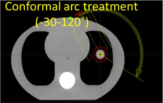
The axial CT slice image of the CIRS phantom and the 150° dynamic conformal arc plan designed for treating the target. CIRS indicates computerized imaging reference systems; CT, computed tomography.
The DICOM file of the arc plan was exported and converted into extensible markup language (XML), which was readable by the Varian TrueBeam research mode for beam delivery. Both kV and MV imaging sequences were written into the XML file to enable intratreatment imaging. The MV imaging was realized through acquiring beam’s eye view (BEV) cine images using the treatment beam’s exit fluence during the arc delivery. So no additional imaging dose was introduced by the BEV MV projections.
After treatment planning and XML file programming, the CIRS phantom was placed on the treatment couch and aligned to the planned position using pretreatment CBCT localization. After the alignment, the treatment couch was shifted by known magnitudes (5 mm) along 3 spatial directions, either individually or in combination, to create different intratreatment target positioning deviations. After each couch shift, the planned arc treatment was delivered to the phantom in Varian TrueBeam research mode using the imaging-enabled XML file. The acquired kV and BEV MV projections from each delivery were exported. Similar to the retrospective patient study, each onboard kV projection was downsampled to 512 × 384 pixels, with each pixel measuring 0.776 × 0.776 mm. The BEV MV projections were similarly downsampled to 512 × 384 pixels, with each pixel measuring 0.784 mm × 0.784 mm. The BEV MV projections were subsequently interpolated to the kV projection grids with the same 0.776 mm resolution so they could be aggregated for reconstruction. Similar to the retrospective patient study, manual phase sorting was used to identify the respiratory phase of each projection for the phase-matching purpose.
Due to the energy discrepancy between kV (120 kVp) and MV (6 MV) projections, the intensity range of BEV MV projections was different from that of kV projections. The BEV MV projections cannot be aggregated directly with kV projections for DTS reconstruction. To correct the intensity differences, the BEV MV projections were converted33 to synthesize corresponding kV projections through a fitted linear relationship between kV and MV projection intensity maps. As shown in Figure 7, pretreatment kV and MV projections were acquired for the phantom at the same imaging angle. A region of interest surrounding the target was selected, and its corresponding pixel values within kV and MV projections were used as y- and x-axis values to derive a linear relationship. The BEV cine MV projections acquired during the arc were then converted to the synthetic kV projections based on the derived linear function.
Figure 7.

Generation of the synthetic kV projections based on a linear relationship derived between kV and MV projection intensities using pretreatment projection pairs. Note that the synthetic kV projection is slightly truncated at the boundary to remove the leakage signal from the multileaf collimator leaves.
Detailed image acquisition and OV-PMDTS reconstruction workflow is shown in Figure 8. Similar to the patient study, the 4 different methods: SV-CDTS, SV-PMDTS, OV-CDTS, and OV-PMDTS were evaluated and compared for their tumor localization accuracy, under various total scan angles.
Figure 8.

A, Scheme of incorporating kV imaging and BEV cine MV imaging into plan delivery through the Varian TrueBeam research mode. B, Flowchart of using the aggregated kV and BEV cine MV projections to reconstruct OV-PMDTS for tumor localization. Pretreatment is the stage at which a linear correlation between kV and MV projection intensities is derived using pretreatment kV and MV projections. The linear correlation is then applied to intratreatment BEV cine MV projections to synthesize kV projections. Note that the 2 intratreatment kV projection sets marked by stars are the same projection set duplicated to facilitate scheme drawing. BEV indicates beams’ eye view; OV-PMDTS, orthogonal-view phase-matched digital tomosynthesis.
In the kV–MV study, the feasibility of continuous tumor tracking by OV-PMDTS is also evaluated. In detail, continuous tumor localizations were performed using DTS images reconstructed by consecutive 10° scan angles throughout the treatment (Figure 9), for the scenario when the tumor was shifted by 5 cm along each of the 3 spatial directions. The OV-PMDTS localization results were compared against those by the SV-PMDTS, the OV-CDTS, and the SV-CDTS techniques. The single-view DTS scans were reconstructed using a 20° scan angle with 10° overlap between consecutive scan angles. A total of 14 consecutive localizations were performed through the 150° arc treatment (Figure 6).
Figure 9.

The scheme for continuous DTS localization in the kV–MV study. A verification point is assessed when the gantry rotates every 10°. For each verification point, the orthogonal-view DTS is reconstructed using 10° kV projections and 10° BEV cine MV projections for tumor localization. BEV indicates beams’ eye view; DTS, digital tomosynthesis.
Tumor Localization Through Image Registration
Tumor localization requires registrations between the RDTS and OBDTS images. Manual registrations between RDTS and OBDTS for tumor localization are subjective and challenging due to the image blurriness and structure distortions. We used an automatic registration algorithm to register the tumors in RDTS to OBDTS. Specifically, the open-source package-Elastix34 was used for image registration. Elastix is a highly customizable registration package and has been extensively used in many research projects.35–37
Using Elastix, shift-only rigid registration was performed for tumor localization based on the mutual information similarity metric. Specifically, we first performed a coarse registration of the whole 3D image volume. Based on the coarse registration, a second registration using a region of interest encompassing the tumor was further performed to fine tune the results.
Evaluation of Tumor Localization Accuracy
For the retrospective patient study, we defined the registered tumor shifts between RCT and onboard CBCT images as the “standard” tumor localization results for reference. A localization error metric was defined to quantitatively compare the registered tumor shifts of each DTS technique to the “standard” localization results of CBCT:
| 1 |
where x, y, and z are the registered tumor shifts by each DTS technique along the 3 spatial directions; xs, ys and zs are the corresponding registered tumor shifts by the CBCT technique.
For the kV–MV study, the couch was moved with known shifts to create onboard tumor positioning deviations. Digital tomosynthesis localization errors were calculated as the differences between the registered tumor shifts by the DTS techniques and the known shifts.
Results
Patient Study Using Limited-Angle kV Projections
Figure 10 shows the OBDTS images reconstructed from single-view and orthogonal-view projections for the retrospective patient study. It is evident that the orthogonal-view acquisition substantially improved the depth information, adding valuable information in the coronal view for tumor localization (Figure 10B vs D).
Figure 10.

Patient OBDTS images reconstructed from single-view projections (A and B) and orthogonal-view projections (C and D). The total scan angle (15°) is preserved through splitting it into equal halves (7.5°) for the orthogonal-view acquisition. OBDTS indicates onboard digital tomosynthesis.
Figure 11 compares the OBDTS with the conventional RDTS and the PMRDTS. Through respiratory phase-matching, the PMRDTS images showed motion blurriness patterns similar to those of the OBDTS images. In comparison, the respiratory motion information was not preserved during the conventional RDTS synthesis. The tumor regions of the resulting conventional RDTS images mismatched with those of the OBDTS images, introducing additional localization errors. Note that although the scan angle (30°) is relatively large, the OBDTS on the second row only contains 5 respiratory phases around the end-of-expiration phase and presents less motion blurriness. It is caused by the extended breathing cycle length of the patient during the OBDTS acquisition.
Figure 11.

Visual comparison between the OBDTS images, the RDTS images synthesized by the conventional DTS technique, and the RDTS images synthesized by the phase-matched DTS technique. The OBDTS images are reconstructed from single-view 30° projections. Each row shows image sets of a different patient. The left column shows the OBDTS images. The middle column shows the RDTS images synthesized using the conventional DTS technique. The right column shows the RDTS images synthesized using the phase-matched DTS technique. OBDTS indicates onboard digital tomosynthesis; RDTS, reference digital tomosynthesis.
Figure 12 compares the tumor localization accuracy (shown as the localization errors relative to CBCT, which were defined in Equation 1) between the SV-CDTS, SV-PMDTS, OV-CDTS, and OV-PMDTS techniques for different scan angles. For 0° total scan angle, the average (± standard deviation [SD]) localization errors of SV-CDTS, SV-PMDTS, OV-CDTS, and OV-PMDTS were 9.0 (7.7) mm, 7.2 (7.8) mm, 4.7 (2.1) mm, and 3.6 (1.9) mm, respectively. For 8° total scan angle, the corresponding results were 7.0 (6.3) mm, 4.8 (6.5) mm, 4.1 (3.8) mm, and 2.7 (1.4) mm, respectively. For 15° total scan angle, the results were 5.2 (4.1) mm, 2.6 (1.2) mm, 4.0 (6.0) mm and 2.2 (0.9) mm, respectively. For 30° total scan angle, the results were 3.1 (1.4) mm, 2.1 (0.8) mm, 3.0 (3.0) mm, and 1.8 (0.7) mm, respectively.
Figure 12.

Comparison of tumor localization accuracy (relative to CBCT) between different DTS techniques for the retrospective patient study. Each boxplot contained 30 localization results corresponding to the 30 cone-beam projection sets studied for the 14 patients. The localization errors of the DTS techniques were calculated relative to the localization results of CBCT, which were treated as the “standard” for reference. The scan angle shown beside each DTS technique label is either the total scan angle (for single-view DTS) or the halved total scan angle at each orthogonal direction (for orthogonal-view DTS). In each boxplot, the upper edge, the central line, and the lower edge of the box represent the 75 percentile (Q3), median, and 25 percentile (Q1) of the data, respectively. The lower whisker extends to the datum no smaller than Q1−1.5×(Q3−Q1), and the upper whisker extends to the datum no larger than Q3+1.5×(Q3−Q1). The “+” in the plots are outliers outside the whiskers. The boxplots make no assumptions of the data distribution and are nonparametric. CBCT indicates cone-beam computed tomography; DTS, digital tomosynthesis.
In general, orthogonal-view DTS techniques generated smaller localization errors than single-view DTS techniques. The superiority of orthogonal-view DTS became more evident when the scan angle decreases (Figure 12D vs C). In addition, the DTS techniques with phase-matching provided better tumor localization than conventional DTS techniques without phase-matching. Among the 4 techniques, OV-PMDTS offered the best localization accuracy as it combined the benefits of orthogonal-view acquisition and phase-matching.
Phantom Study Using Intratreatment kV and BEV MV Projections
In Figure 13, the first column shows the orthogonal-view OBDTS, and the other 4 columns show the RDTS sets synthesized by different DTS techniques. The OV-PMDTS generated an RDTS image with the target region best matched with that of the OBDTS image. Without phase-matching, the target region generated by the OV-CDTS technique mismatched with that of the OBDTS image. Without the complementary information from the orthogonal-view acquisition, the target regions generated by the SV-PMDTS and SV-CDTS techniques displayed much worse resolution in the coronal view. Note that the RDTS sets generated by the single-view DTS techniques (SV-PMDTS and SV-CDTS) were registered to the single-view OBDTS sets for tumor localization not the orthogonal-view OBDTS shown in Figure 13.
Figure 13.

Comparison between onboard DTS and different RDTS sets generated by different techniques for the kV–MV study. RDTS indicates reference digital tomosynthesis.
Figure 14 shows the localization errors of different DTS techniques for the kV–MV study. Figure 14A shows the localization error boxplots of different DTS techniques with fixed scan directions but varying total scan angles (0°-60°). Combining orthogonal-view acquisition and phase-matching, the OV-PMDTS technique localized the tumor to an average error within 1 mm (0.7 (0.4) mm). On the other hand, Figure 14B shows the localization errors of different DTS techniques with fixed total scan angles (20°) but varying scan directions (for the continuous localization scheme shown in Figure 9). The 14 evaluated scan directions evenly spread across the whole treatment arc with 10° intervals. For all scan directions, the OV-PMDTS technique localized the tumor to an average (± SD) error of 1.2 (0.6) mm, as compared to 5.9 (3.1) mm of the OV-CDTS technique, 1.8 (0.9) mm of the SV-PMDTS technique, and 4.7 (2.0) mm of the SV-CDTS technique.
Figure 14.

A, Tumor localization error boxplots of different DTS techniques with fixed scan directions but varying total scan angles ranging from 0° to 60° (0°, 5°, 10°, 20°, 40°, and 60°). Each scan angle has 5 localization results, corresponding to 5 onboard tumor deviation scenarios created: no shift, 5 mm shift along the longitudinal direction, 5 mm shift along the vertical direction, 5 mm shift along the lateral direction, and 5 mm shifts along each of the 3 directions. Thus in each boxplots there are 30 data points. B, Tumor localization errors of different DTS techniques with fixed total scan angles (20°) but varying scan directions (each column shows results from a different scan direction). The tumor position was deviated onboard with 5 mm shifts along each of the 3 directions. DTS indicates digital tomosynthesis.
Discussion
Due to the lack of the “ground-truth” tumor localization results for the patient study, the localization results of CBCT were used as the “standard” for reference in our study. Cone-beam computed tomography was routinely used for lung tumor localization in clinical practice, of which the accuracy has been verified by multiple studies.38–40 The retrospective patient study demonstrated the accuracy of the OV-PMDTS technique in tumor localization, as compared to other DTS techniques (Figure 12). The orthogonal-view acquisition improved the depth information (Figure 10) to enable more accurate tumor localization. The phase-matching successfully incorporated the respiratory motion information into RDTS synthesis, generating PMRDTS images with tumor motion blurriness patterns similar to those of OBDTS images (Figure 11). As a result, the impacts of tumor motion were reduced to enable more accurate localization (Figure 12).
For PMDTS, its localization accuracy is dependent on the scan angle, rather than the number of phases contained.7 The phase-matching technique essentially minimizes the effects of number of phases on the registration accuracy by matching the phases between reference and onboard images. The tumor regions in the OBDTS and RDTS will show similar blurriness patterns, as long as the phases are correctly matched between these 2 DTS sets, regardless of the number of contained phases. In contrast, the magnitude of scan angle is more critical as it directly determines the amount of depth information DTS captures for tumor localization. In this study, we used different magnitudes of scan angles and summarized the results in Figure 12. The minimum arc length needed for accurate tumor localization is dependent on the complexity of the studied object. Real patients (Figure 12) are more complex than the anthropomorphic CIRS phantom (Figure 14), thus they generally require a larger arc length for accurate tumor localization. In general, a 30° arc length is mostly sufficient for accurate localization, which matches our previous findings.7
The preliminary intratreatment tumor localization study using aggregated kV and BEV cine MV projections demonstrated the feasibility of orthogonal-view acquisition using the current clinical LINACs. The use of BEV MV projections (Figures 7 –9) conveniently reduced the total scan time by more than half. It also reduced the total scan dose by half, as the BEV cine MV projections were by-products of the treatment beams and did not introduce additional imaging dose. It should be noted that stretching kV and MV imaging arms out together for orthogonal-view imaging may potentially decrease mechanical clearance as compared to single-view imaging. In this scenario, we can set the electronic portal imaging device and onboard imager at a larger distance from the isocenter, for example, 60 to 70 cm, during imaging acquisition to avoid the mechanical clearance issue. Same as the retrospective patient study, the kV–MV study proved the superiority of OV-PMDTS in tumor localization (Figure 14). As demonstrated by the results shown in Figure 14B, OV-PMDTS can be generated on-the-fly during the actual arc delivery for tumor localization once a limited-angle projection set is acquired, which enables continuous tumor localization throughout the treatment. In comparison, CBCT is incapable of this continuous, fast tumor localization during the treatment, due to the full rotation angle required. The intratreatment verification by DTS allows us to continuously monitor the tumor drift throughout the radiation delivery and interrupt the treatment when the tumor positioning error is larger than the planning target volume margin. This unique advantage of DTS helps us minimize the treatment errors, which is especially important for stereotactic body radiation therapy treatments.41,42 Due to the lack of kV–MV acquisition protocols in the clinical treatment mode, only phantom measurement was performed in our kV–MV study. Future comprehensive evaluations using real patient data are warranted. In addition to tumor localization in conformal arc treatments, the proposed kV–MV localization scheme can also be readily applied towards tumor localization between static 3D/intensity-modulated radiation therapy (IMRT) beams.16 For these scenarios, when the gantry rotates from one beam to another, DTS images can be quickly generated using the limited-angle projections acquired during the gantry rotation for tumor localization. Note that although each IMRT beam is modulated with truncated tumor views, the MV fields can be opened up to acquire untruncated views of the tumor during gantry rotation between consecutive IMRT beams. In contrast, for volumetric modulated arc therapy (VMAT) treatments, the views of the tumor will mostly be truncated in the MV projections, as the MV beam aperture is fully constrained by the plan at all gantry angles. In the current study, we evaluated the kV–MV technique on a conformal arc treatment, which is not affected by the issue of tumor view truncations. We conjecture the accuracy of the kV–MV DTS technique with truncated tumor views will be somewhere in between single-view DTS technique using kV projections only, and kV–MV DTS techniques without tumor view truncations, due to partially acquired MV image information. However, future evaluations based on VMAT treatments are warranted to quantitatively evaluate the effects of tumor view truncations. Note that for multiarc VMAT, we can still do kV–MV based DTS localization between consecutive arcs without view truncations.
The 4D-DTS17–20 is a technique that can capture trajectories of moving targets to potentially enable accurate lung tumor localization. However, the 4D-DTS technique needs to acquire over-sampled projections using a slow-gantry acquisition scheme, such that the respiratory-resolved 3D OBDTS images at each phase will not be severely affected by the under-sampling issue. In comparison, our PMDTS technique only needs to acquire a 3D OBDTS for localization using normal gantry rotation speed. Correspondingly, the 4D-DTS technique will take longer acquisition time and increase the scan dose, which is suboptimal as compared to the PMDTS technique, especially for intrafractional verification. Though there is a study20 which acquired 4D-DTS images by using normal gantry rotation speed, it only sorted the projections into 4 respiratory phase bins, instead of the common 10 bins used in other 4D-DTS studies,17,18 or in conventional 4D-CT/4D-CBCT. The 4 phases were used mainly to avoid effects from severe under-sampling in each phase bin, since very limited projections were acquired from the normal-gantry acquisition. However, reducing the number of phases from 10 to 4 will inevitably introduce more intraphase motion blurriness, and lead to potentially less accurate tumor trajectory delineation and tumor localization. To improve the localization accuracy of 4D-DTS, more projections will be needed to reconstruct more phases of 4D-DTS to minimize the effect of intraphase motion blurriness on the registration accuracy. Our previous publications17,18 studied the amount of projections needed in different scenarios. Nonetheless, we acknowledge that comprehensive evaluation and comparison between the PMDTS technique and the 4D-DTS technique are needed before any solid conclusion can be drawn. Such a study is beyond the scope of the current work and will be investigated in the future when sufficient 4D-DTS data become available.
In this pilot study, the DTS localization was performed in an off-line fashion. The whole DTS localization scheme needs to be further accelerated to enable online tumor localization. Currently, 3 factors have slowed the DTS localization process: (1) manual projection phase identification, (2) DTS image reconstruction, and (3) Elastix-based DTS registration. In this study, we manually tracked the diaphragms in the projections for phase-sorting, which was time-consuming. However, for real clinical practice, we can refer to existing phase-tracking techniques based on external surrogates tracking (such as the Varian real-time position management system, the Anzai Belt and the VisionRT system) for real-time phase tracking. Techniques based on internal anatomical features or landmarks can also be used for fast phase identification (such as the Fourier transform based technique,43 the Amsterdam shroud technique44, etc). These approaches can all substantially accelerate the phase-sorting process to enable real-time phase identification. Note that for scenarios where the kV and MV projections are not simultaneously acquired (so they won’t share the same phases), the phase identification of MV projections based on anatomical surrogates might be more challenging due to their low contrast. In these scenarios, the external marker-based tracking techniques can be readily applied. Currently, the DTS images were reconstructed using the central processing unit–based FDK algorithm. The DTS reconstruction using limited-angle projections was faster than the CBCT reconstruction but could still take up to 1 minute. Graphics processing unit (GPU)-based FDK reconstruction has already been developed, which enables clinical image reconstruction within 1 second.45 The GPU acceleration can be used to substantially reduce the DTS reconstruction time. The Elastix-based rigid registration currently takes around 3 to 5 minutes for each case. The potential speed-up factor has been reported by other GPU-based studies to be 100×,46 though for a more complicated deformable registration algorithm. Similarly, we can add GPU-based acceleration47 to the current Elastix package to achieve faster image registration. With these potential accelerations, it is promising that the DTS localization can be performed within seconds to meet the current clinical time constraint.
In this study, the Elastix-based registration is fully automatic. There are scenarios in which the registration is trapped at a local optimum, resulting in large errors classified as localization outliers (Figure 12). We also noticed similar issues in the phantom-based PMDTS study.7 One solution is to visually verify the results after the automatic registration and apply necessary corrections, however, at the cost of reduced registration efficiency. The registration accuracy may also be improved by using an initial guess, setting bounds on the possible shifts, or using more robust registration algorithms such as the simulated annealing. In addition, the tumor localization in this study was performed through shift-only registration without considering rotations, similar to what is routinely done in clinical practice. The registration of rotation is challenging for DTS image due to its anisotropic resolution distributions. From a dosimetric perspective,48 rotation is less of a concern as compared to translational shifts for radiotherapy of lung cancer. High-quality DTS images reconstructed using advanced techniques, especially those techniques incorporating prior information,6,21,49–51 can potentially be used for accurate registrations of rotations. However, these techniques have higher computational cost and longer reconstruction time.
In addition to the 3D–3D DTS registrations performed in this study, we can also perform 2D–2D image registrations using only DRR and OBP pairs (without DTS reconstruction) and combine their results to solve the 3D shifts between the reference 4D-CT and the onboard patient volume. However, the accuracy and efficiency of this approach are limited by several factors, including:
1. Single 2D projection image usually lacks sufficient soft tissue intensity variations and contrast for accurate registration, especially, when the tumor is overlapped with high-density structures such as bone in the projection image. The large inaccuracy associated with each 2D registration will be propagated and increase the overall registration errors. In contrast, DTS images are reconstructed from the collective information of 2D projections, which presents substantially improved soft tissue contrast to enable direct, more accurate 3D–3D tomographic registration.
2. When multiple 2D projection pairs are used for registration, triangulations are needed to convert the registered planar shifts into 3D shifts, which might introduce additional errors.
3. Due to the large errors associated with 2D–2D registrations, multiple iterations are potentially needed to refine the registration results to match with the multiple sets of 2D images overall, leading to an iterative 4D–2D registration problem (4D-CT to 2D projections registration). The DRR regeneration and 2D registration processes involved in each iteration will substantially increase the overall computation time, which is much less efficient than the 3D–3D registration approach.
4. In addition, for clinicians, the registration of two 3D DTS images will be more convenient and easier than registering multiple 2D image pairs, if manual registration is to be performed.
Conclusion
In conclusion, the retrospective patient study validated the superiority of the OV-PMDTS technique in lung tumor localization over single-view or conventional DTS techniques without phase-matching. The preliminary intratreatment tumor localization study using aggregated kV and BEV cine MV projections also demonstrated the potential of OV-PMDTS for real-time tumor tracking during the treatment delivery. Future studies enrolling a large patient cohort are warranted to further evaluate the robustness of the OV-PMDTS technique and explore its potential for intratreatment verification.
Abbreviations
- AIP
average intensity projection
- BEV
beam’s eye view
- CBCT
cone-beam computed tomography
- CIRS
computerized imaging reference systems
- DRR
digitally reconstructed radiograph
- DTS
digital tomosynthesis
- FDK
Feldkamp-Davis-Kress
- GPS
global positioning system
- GPU
graphics processing unit
- IMRT
intensity-modulated radiation therapy
- LINAC
linear accelerator
- MIP
maximum intensity projection
- OBDTS
onboard digital tomosynthesis
- OBP
onboard projection
- OV-CDTS
orthogonal-view conventional digital tomosynthesis
- OV-PMDTS
orthogonal-view phase-matched digital tomosynthesis
- PET-CT
positron emission tomography-computed tomography
- RCT
reference computed tomography
- RDTS
reference digital tomosynthesis
- SV-CDTS
single-view conventional digital tomosynthesis
- SV-PMDTS
single-view phase-matched digital tomosynthesis
- VMAT
volumetric modulated arc therapy
- XML
extensible markup language
- 4D-RCT
4-dimensional reference computed tomography
Footnotes
Author’s Note: Lei Ren is a co-first author with equal contribution.
Declaration of Conflicting Interests: The author(s) declared no potential conflicts of interest with respect to the research, authorship, and/or publication of this article.
Funding: The author(s) disclosed receipt of the following financial support for the research, authorship, and/or publication of this article: This work was supported by a NIH Grant No. R01-CA184173 and a research grant from Varian Medical Systems.
References
- 1. Dawson LA, Jaffray DA. Advances in image-guided radiation therapy. J Clin Oncol. 2007;25(8):938–946. [DOI] [PubMed] [Google Scholar]
- 2. Jaffray DA, Siewerdsen JH. Cone-beam computed tomography with a flat-panel imager: initial performance characterization. Med Phys. 2000;27(6):1311–1323. [DOI] [PubMed] [Google Scholar]
- 3. Letourneau D, Wong JW, Oldham M, et al. Cone-beam-CT guided radiation therapy: technical implementation. Radiother Oncol. 2005;75(3):279–286. [DOI] [PubMed] [Google Scholar]
- 4. Godfrey DJ, Yin FF, Oldham M, Yoo S, Willett C. Digital tomosynthesis with an on-board kilovoltage imaging device. Int J Radiat Oncol Biol Phys. 2006;65(1):8–15. [DOI] [PubMed] [Google Scholar]
- 5. Wu QJ, Godfrey DJ, Wang Z, et al. On-board patient positioning for head-and-neck IMRT: comparing digital tomosynthesis to kilovoltage radiography and cone-beam computed tomography. Int J Radiat Oncol Biol Phys. 2007;69(2):598–606. [DOI] [PubMed] [Google Scholar]
- 6. Ren L, Zhang J, Thongphiew D, et al. A novel digital tomosynthesis (DTS) reconstruction method using a deformation field map. Med Phys. 2008;35(7):3110–3115. [DOI] [PMC free article] [PubMed] [Google Scholar]
- 7. Zhang Y, Ren L, Ling CC, Yin FF. Respiration-phase-matched digital tomosynthesis imaging for moving target verification: a feasibility study. Med Phys. 2013;40(7):071723. [DOI] [PubMed] [Google Scholar]
- 8. Booth JT, Caillet V, Hardcastle N, et al. The first patient treatment of electromagnetic-guided real time adaptive radiotherapy using MLC tracking for lung SABR. Radiother Oncol. 2016;121(1):19–25. [DOI] [PubMed] [Google Scholar]
- 9. Shah AP, Kupelian PA, Willoughby TR, Langen KM, Meeks SL. An evaluation of intrafraction motion of the prostate in the prone and supine positions using electromagnetic tracking. Radiother Oncol. 2011;99(1):37–43. [DOI] [PubMed] [Google Scholar]
- 10. Purdie TG, Bissonnette JP, Franks K, et al. Cone-beam computed tomography for on-line image guidance of lung stereotactic radiotherapy: localization, verification, and intrafraction tumor position. Int J Radiat Oncol Biol Phys. 2007;68(1):243–252. [DOI] [PubMed] [Google Scholar]
- 11. Hyer DE, Serago CF, Kim S, Li JG, Hintenlang DE. An organ and effective dose study of XVI and OBI cone-beam CT systems. J Appl Clin Med Phys. 2010;11(2):3183. [DOI] [PMC free article] [PubMed] [Google Scholar]
- 12. Kim DW, Chung WK, Yoon M. Imaging doses and secondary cancer risk from kilovoltage cone-beam CT in radiation therapy. Health physics. 2013;104(5):499–503. [DOI] [PubMed] [Google Scholar]
- 13. Maravilla KR, Murry RC, Jr, Horner S. Digital tomosynthesis: technique for electronic reconstructive tomography. AJR Am J Roentgenol. 1983;141(3):497–502. [DOI] [PubMed] [Google Scholar]
- 14. Dobbins JT III, Godfrey DJ. Digital x-ray tomosynthesis: current state of the art and clinical potential. Phys Med Biol. 2003;48(19):R65–R106. [DOI] [PubMed] [Google Scholar]
- 15. Zhang P, Hunt M, Pham H, Tang G, Mageras G. Intrafractional 3D localization using kilovoltage digital tomosynthesis for sliding-window intensity modulated radiation therapy. Phys Med Biol. 2015;60(17):N335–N344. [DOI] [PMC free article] [PubMed] [Google Scholar]
- 16. Ren L, Zhang Y, Yin FF. A limited-angle intrafraction verification (LIVE) system for radiation therapy. Med Phys. 2014;41(2):020701. [DOI] [PubMed] [Google Scholar]
- 17. Maurer J, Godfrey D, Wang Z, Yin FF. On-board four-dimensional digital tomosynthesis: first experimental results. Med Phys. 2008;35(8):3574–3583. [DOI] [PubMed] [Google Scholar]
- 18. Maurer J, Pan T, Yin FF. Slow gantry rotation acquisition technique for on-board four-dimensional digital tomosynthesis. Med Phys. 2010;37(2):921–933. [DOI] [PubMed] [Google Scholar]
- 19. Park JC, Kim JS, Park SH, et al. Four dimensional digital tomosynthesis using on-board imager for the verification of respiratory motion. PLoS One. 2014;9(12):e115795. [DOI] [PMC free article] [PubMed] [Google Scholar]
- 20. Santoro J, Kriminski S, Lovelock DM, et al. Evaluation of respiration-correlated digital tomosynthesis in lung. Med Phys. 2010;37(3):1237–1245. [DOI] [PMC free article] [PubMed] [Google Scholar]
- 21. Zhang Y, Yin FF, Segars WP, Ren L. A technique for estimating 4D-CBCT using prior knowledge and limited-angle projections. Med Phys. 2013;40(12):121701. [DOI] [PubMed] [Google Scholar]
- 22. Yoo S, Wu QJ, Godfrey D, et al. Clinical evaluation of positioning verification using digital tomosynthesis and bony anatomy and soft tissues for prostate image-guided radiotherapy. Int J Radiat Oncol Biol Phys. 2009;73(1):296–305. [DOI] [PMC free article] [PubMed] [Google Scholar]
- 23. Godfrey DJ, Ren L, Yan H, et al. Evaluation of three types of reference image data for external beam radiotherapy target localization using digital tomosynthesis (DTS). Med Phys. 2007;34(8):3374–3384. [DOI] [PubMed] [Google Scholar]
- 24. Siddon RL. Fast calculation of the exact radiological path for a three-dimensional CT array. Med Phys. 1985;12(2):252–255. [DOI] [PubMed] [Google Scholar]
- 25. Huang L, Park K, Boike T, et al. A study on the dosimetric accuracy of treatment planning for stereotactic body radiation therapy of lung cancer using average and maximum intensity projection images. Radiother Oncol. 2010;96(1):48–54. [DOI] [PubMed] [Google Scholar]
- 26. Keall PJ, Starkschall G, Shukla H, et al. Acquiring 4D thoracic CT scans using a multislice helical method. Phys Med Biol. 2004;49(10):2053–2067. [DOI] [PubMed] [Google Scholar]
- 27. Pan T, Lee TY, Rietzel E, Chen GT. 4D-CT imaging of a volume influenced by respiratory motion on multi-slice CT. Med Phys. 2004;31(2):333–340. [DOI] [PubMed] [Google Scholar]
- 28. Hof H, Rhein B, Haering P, Kopp-Schneider A, Debus J, Herfarth K. 4D-CT-based target volume definition in stereotactic radiotherapy of lung tumours: comparison with a conventional technique using individual margins. Radiother Oncol. 2009;93(3):419–423. [DOI] [PubMed] [Google Scholar]
- 29. Feldkamp LA, Davis LC, Kress JW. Practical cone-beam algorithm. J Opt Soc Am A. 1984;1(6):612–619. [Google Scholar]
- 30. Giles W, Bowsher J, Li H, Yin FF. Interleaved acquisition for cross scatter avoidance in dual cone-beam CT. Med Phys. 2012;39(12):7719–7728. [DOI] [PubMed] [Google Scholar]
- 31. Li H, Giles W, Bowsher J, Yin FF. A dual cone-beam CT system for image guided radiotherapy: initial performance characterization. Med Phys. 2013;40(2):021912. [DOI] [PubMed] [Google Scholar]
- 32. Luo W, Yoo S, Wu QJ, Wang Z, Yin FF. Analysis of image quality for real-time target tracking using simultaneous kV-MV imaging. Med Phys. 2008;35(12):5501–5509. [DOI] [PubMed] [Google Scholar]
- 33. Yin FF, Guan H, Lu W. A technique for on-board CT reconstruction using both kilovoltage and megavoltage beam projections for 3D treatment verification. Med Phys. 2005;32(9):2819–2826. [DOI] [PubMed] [Google Scholar]
- 34. Klein S, Staring M, Murphy K, Viergever MA, Pluim JP. Elastix: a toolbox for intensity-based medical image registration. IEEE Trans Med Imaging. 2010;29(1):196–205. [DOI] [PubMed] [Google Scholar]
- 35. Kerkhof EM, van der Put RW, Raaymakers BW, van der Heide UA, Jurgenliemk-Schulz IM, Lagendijk JJ. Intrafraction motion in patients with cervical cancer: The benefit of soft tissue registration using MRI. Radiother Oncol. 2009;93(1):115–121. [DOI] [PubMed] [Google Scholar]
- 36. van Rikxoort EM, Prokop M, de Hoop B, Viergever MA, Pluim JP, van Ginneken B. Automatic segmentation of the pulmonary lobes from fissures, airways, and lung borders: evaluation of robustness against missing data. Med Image Comput Comput Assist Interv. 2009;12(pt 1):263–271. [DOI] [PubMed] [Google Scholar]
- 37. Ding K, Bayouth JE, Buatti JM, Christensen GE, Reinhardt JM. 4DCT-based measurement of changes in pulmonary function following a course of radiation therapy. Med Phys. 2010;37(3):1261–1272. [DOI] [PMC free article] [PubMed] [Google Scholar]
- 38. Hugo GD, Liang J, Campbell J, Yan D. On-line target position localization in the presence of respiration: a comparison of two methods. Int J Radiat Oncol Biol Phys. 2007;69(5):1634–1641. [DOI] [PMC free article] [PubMed] [Google Scholar]
- 39. Bissonnette JP, Purdie TG, Higgins JA, Li W, Bezjak A. Cone-beam computed tomographic image guidance for lung cancer radiation therapy. Int J Radiat Oncol Biol Phys. 2009;73(3):927–934. [DOI] [PubMed] [Google Scholar]
- 40. Kamomae T, Monzen H, Nakayama S, et al. Accuracy of image guidance using free-breathing cone-beam computed tomography for stereotactic lung radiotherapy. PLoS One. 2015;10(5):e0126152. [DOI] [PMC free article] [PubMed] [Google Scholar]
- 41. Li W, Purdie TG, Taremi M, et al. Effect of immobilization and performance status on intrafraction motion for stereotactic lung radiotherapy: analysis of 133 patients. Int J Radiat Oncol Biol Phys. 2011;81(5):1568–1575. [DOI] [PubMed] [Google Scholar]
- 42. Zhao B, Yang Y, Li T, Li X, Heron DE, Huq MS. Dosimetric effect of intrafraction tumor motion in phase gated lung stereotactic body radiotherapy. Med Phys. 2012;39(11):6629–6637. [DOI] [PubMed] [Google Scholar]
- 43. Vergalasova I, Cai J, Yin FF. A novel technique for markerless, self-sorted 4D-CBCT: feasibility study. Med Phys. 2012;39(3):1442–1451. [DOI] [PMC free article] [PubMed] [Google Scholar]
- 44. Sonke JJ, Zijp L, Remeijer P, van Herk M. Respiratory correlated cone beam CT. Med Phys. 2005;32(4):1176–1186. [DOI] [PubMed] [Google Scholar]
- 45. Park JC, Park SH, Kim JS, et al. Ultra-fast digital tomosynthesis reconstruction using general-purpose GPU programming for image-guided radiation therapy. Technol Cancer Res Treat. 2011;10(4):295–306. [DOI] [PubMed] [Google Scholar]
- 46. Gu X, Pan H, Liang Y, et al. Implementation and evaluation of various demons deformable image registration algorithms on a GPU. Phys Med Biol. 2010;55(1):207–219. [DOI] [PMC free article] [PubMed] [Google Scholar]
- 47. Shamonin DP, Bron EE, Lelieveldt BP, et al. Fast parallel image registration on CPU and GPU for diagnostic classification of Alzheimer’s disease. Front Neuroinform. 2013;7:50. [DOI] [PMC free article] [PubMed] [Google Scholar]
- 48. Yang Y, Catalano S, Kelsey CR, Yoo DS, Yin FF, Cai J. Dosimetric effects of rotational offsets in stereotactic body radiation therapy (SBRT) for lung cancer. Med Dosim. 2014;39(1):117–121. [DOI] [PubMed] [Google Scholar]
- 49. Zhang Y, Yin FF, Pan T, Vergalasova I, Ren L. Preliminary clinical evaluation of a 4D-CBCT estimation technique using prior information and limited-angle projections. Radiother Oncol. 2015;115(1):22–29. [DOI] [PMC free article] [PubMed] [Google Scholar]
- 50. Zhang Y, Yin FF, Ren L. Dosimetric verification of lung cancer treatment using the CBCTs estimated from limited-angle on-board projections. Med Phys. 2015;42(8):4783–4795. [DOI] [PMC free article] [PubMed] [Google Scholar]
- 51. Zhang Y, Tehrani JN, Wang J. A biomechanical modeling guided CBCT estimation technique. IEEE Trans Med Imaging. 2017;36(2):641–652. [DOI] [PMC free article] [PubMed] [Google Scholar]