Significance
The movement of immiscible fluids through permeable media occurs in many settings, including oil and water flow through rock. Here we present observations of a previously unidentified type of steady-state flow behavior that we term “dynamic connectivity.” We demonstrate that flow of the nonwetting phase occurs through a network of connections that continuously rearrange between filled pores. This observation suggests that we need to modify our models of two-phase flow that are fundamental to describing subsurface flow processes such as geologic CO2 storage and hydrocarbon recovery.
Keywords: steady state, pore-scale imaging, immiscible two-phase flow, dynamic connectivity, geologic CO2 storage
Abstract
The current conceptual picture of steady-state multiphase Darcy flow in porous media is that the fluid phases organize into separate flow pathways with stable interfaces. Here we demonstrate a previously unobserved type of steady-state flow behavior, which we term “dynamic connectivity,” using fast pore-scale X-ray imaging. We image the flow of N2 and brine through a permeable sandstone at subsurface reservoir conditions, and low capillary numbers, and at constant fluid saturation. At any instant, the network of pores filled with the nonwetting phase is not necessarily connected. Flow occurs along pathways that periodically reconnect, like cars controlled by traffic lights. This behavior is consistent with an energy balance, where some of the energy of the injected fluids is sporadically converted to create new interfaces.
The definition of relative permeability is based on a conceptual model where each phase occupies its own static, connected fraction of the pore space (1–3). Observations of two-phase flow in beadpacks and micromodels at low flow rates show that the wetting- and nonwetting-phase fluids flow through their own network of separate stable pathways. Increasing the saturation of one phase increases the number of channels occupied by one fluid and decreases the number occupied by the other. The nonwetting phase generally occupies the large pores, whereas the wetting phase occupies the small pores and indentations in the surface of the solid (4–7).
When the balance of capillary and viscous forces is modified such that viscous forces begin to dominate at the pore scale, the nonwetting phase can be pushed out of the pore space and flow can occur through the advection of disconnected ganglia (8, 9). The onset of ganglion motion is well understood, and this flow behavior has been observed during steady-state flow in model pore spaces (1–3, 7, 10–13).
The key observation during slow steady-state flow, typical of most displacements in natural settings, such as during hydrocarbon recovery or CO2 storage, is that the pathway, once established, remains stable (2, 4–7). Flow patterns for different wettabilities have also been quantified in micromodel studies (14). Again, once flow pathways were established, they were not observed to change. However, there are no studies thus far that have investigated this flow behavior in the pore space of natural rocks.
Developments in micro X-ray computed tomography (X-ray CT) mean that pore-scale phenomena can now be observed in rocks at reservoir conditions in both laboratory-based scanners and synchrotron beamlines (8, 9, 15–17). This technological advance has allowed, for instance, observations of residual trapping (18) and wetting behavior (19).
Fast synchrotron tomography allows the acquisition of images in under 60 s. Many unsteady-state, dynamic, pore-scale processes have been imaged, including Haines jumps (15), capillary pressure changes during reservoir condition CO2-brine drainage (20), ganglion dynamics during the capillary desaturation of oil (21), and reactive transport processes in complex carbonates (22).
These advances in imaging technology have also allowed new pore-scale mechanisms to be identified. At high flow rates, the fragmentation of large trapped ganglia has been observed in the pore space of a complex carbonate rock (23). At lower capillary numbers, the trapping of CO2 (20) and oil (21) in disconnected ganglia has been quantified in sandstones. The connection and reconnection of ganglia was observed as a result of the local advance and recession of the wetting phase. However, the implications for flow were not quantified, and it was implied that nonwetting-phase displacement occurred by the movement of trapped ganglia through the pore space (21).
Experimental Observations of Steady-State Two-Phase Flow at the Pore Scale
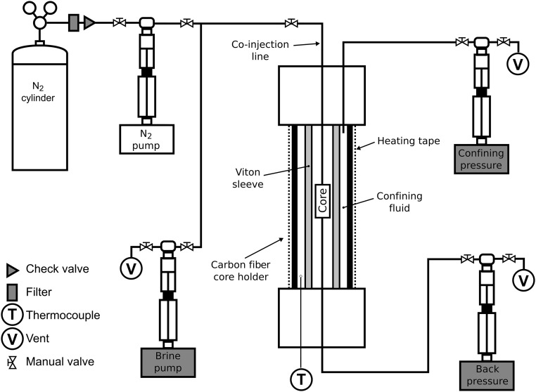
The work presented here is a pore-scale experimental investigation of macroscopic steady-state flow performed at reservoir conditions. We use fast synchrotron X-ray CT to investigate rate-dependent, steady-state two-phase flow behavior at low capillary numbers representative of subsurface flow conditions, well below the threshold for pore-scale ganglion motion, in the pore space of a sandstone. We injected N2 and brine at a constant fractional flow into a sample of Bentheimer sandstone (apparatus shown in Fig. S1). We altered the capillary–viscous force balance by increasing the total flow rate in a stepwise manner. We demonstrate that flow follows fixed flow paths, as in the traditional theory, but that these pathways have critical connections that are periodically filled with wetting phase, blocking flow.
Fig. S1.
Schematic of the flow rig and core holder used for the pore-scale coinjection experiments.
We define wetting- and nonwetting-phase capillary numbers (7, 10),
| [1] |
and
| [2] |
respectively, where the interstitial fluid velocity (in meters per second) is , is the Darcy flux, is the porosity, is the dynamic viscosity (in Pascal seconds), and is the interfacial tension between the wetting and nonwetting phases (in Newtons per meter).
Coinjection experiments were performed in two sets of increasing total flow rate corresponding to an increasing capillary number (experiments 1A to 1D and 2A to 2C, Table 1), each time starting with the pore space fully saturated with brine. Brine and N2 were injected at equal flow rates until an approximately constant saturation was established in the core, and then images were acquired over a period of 28 min to 45 min.
Table 1.
List of experiments
| Experiment | Flow Rate,* mLmin−1 | Caw | Canw | Scan time, min | Mean |
| 1A | 0.02 | 7.00 10−7 | 2.27 10−8 | 44 | 0.274 |
| 1B | 0.10 | 3.50 10−6 | 1.13 10−7 | 35 | 0.225 |
| 1C | 0.30 | 1.05 10−5 | 3.40 10−7 | 45 | 0.302 |
| 1D | 0.50 | 1.75 10−5 | 5.67 10−7 | 42 | 0.321 |
| 2A | 0.04 | 1.40 10−6 | 4.54 10−8 | 29 | 0.358 |
| 2B | 0.30 | 1.05 10−5 | 3.40 10−7 | 28 | 0.340 |
| 2C | 1.00 | 3.50 10−5 | 1.13 10−6 | 28 | 0.354 |
Total flow rate, Qt = Qnw + QW, Where Qnw = QW.
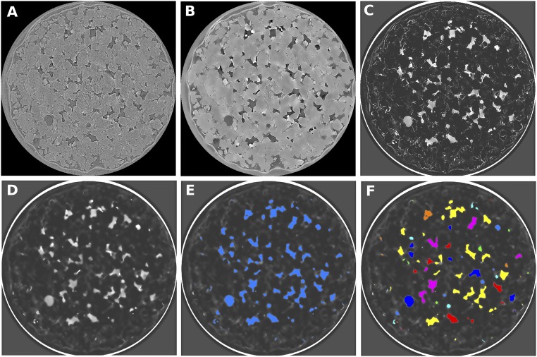
The images were processed using the techniques outlined in Materials and Methods, using Avizo 9.1 (www.vsg3d.com) to create 3D volumes of N2 that could be analyzed to assess their volume and connectivity (Figs. S2 and S3). The steady-state saturation of N2 (Mean ) and the calculated capillary numbers for the wetting and nonwetting phases are given in Table 1.
Fig. S2.
Examples of the steps used to process the synchrotron data and extract volumes of N2. Each image has dimensions 4 mm 4 mm. (A) Raw grayscale image. (B) Image after undergoing nonlocal means filtering, registration to a dry scan, and resampling to align the registered voxels. (C) Difference image created by subtracting a brine scan from the experimental scan. (D) Nonlocal means filtered difference image. (E) Image where watershed segmentation algorithm has been used to identify N2 in blue. (F) Image where individual volumes of N2 have been labeled and colored separately.
Fig. S3.
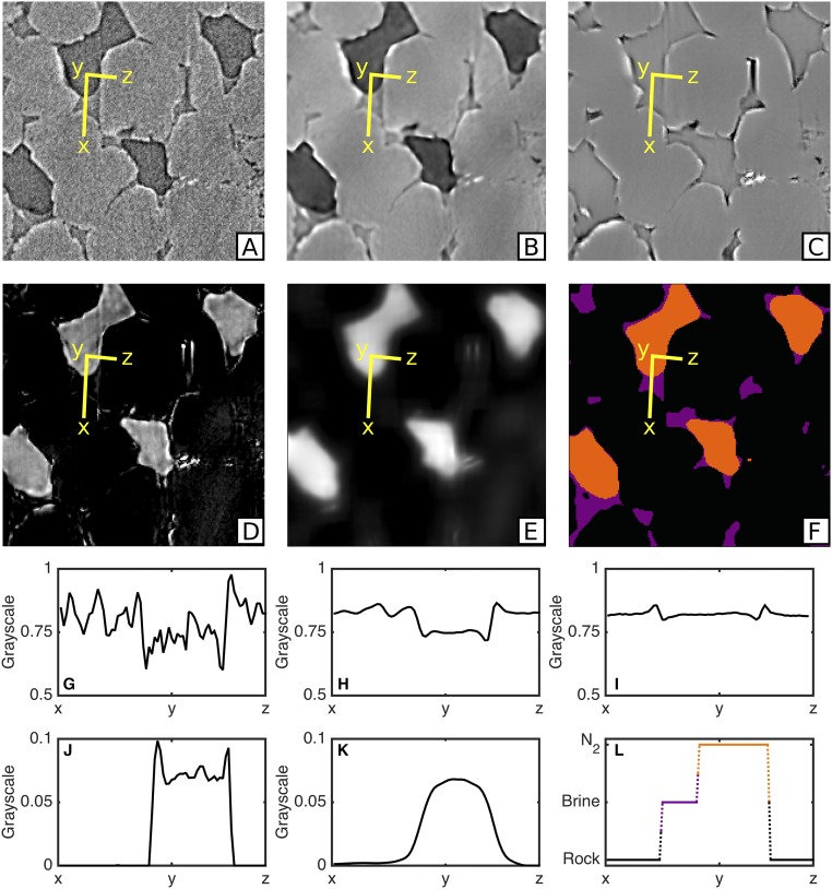
Images at six stages of processing (A–F) are shown along with scaled grayscale profiles across x–y–z (G–L) to illustrate the change in grayscale such that three different phases can be identified (F and L). Each image has dimensions 300 m 300 m (A and G) Raw reconstructed image. (B and H) Filtered image. (C and I) Filtered image (brine only). (D and J) Difference image between B and C. (E and K) Filtered difference image. (F and L) Segmented image.
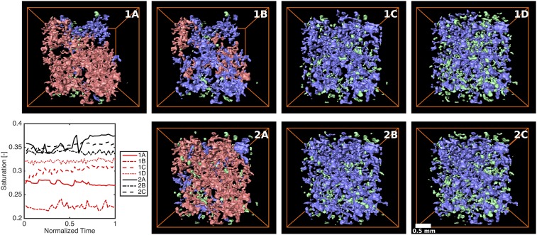
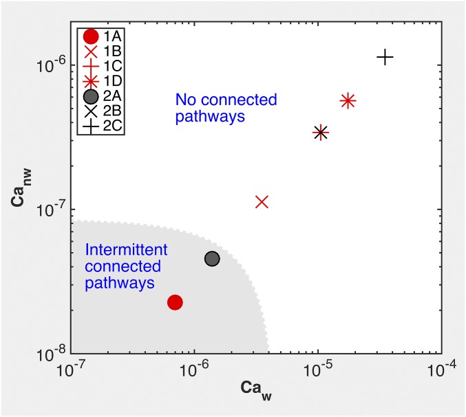
Connected volumes of N2 were observed in the low flow rate, low capillary number experiments (1A and 2A). There were no connected pathways of N2 in experiments 1B to 1D and 2B and 2C, and disconnected ganglia of N2 of various sizes were present in all of the experiments (Fig. 1).
Fig. 1.
Ganglia populations contributing to average saturation. Average saturation is plotted versus time, and volume renderings of ganglia at the end of the experiment are shown, for experiments 1A to 1D and 2A to 2C. Ganglia are subdivided by size: large (pink), medium (blue), and small (green). Flow is from top to bottom. Time from the beginning of the experiment is normalized by the total experimental time (Table 1).
The ganglia populations were subdivided to make visualizing the connectivity easier (Table S1): large ganglia, which typically contain thousands of pores and may be connected across the field of view (pink volumes, Fig. 1, containing more than voxels); medium ganglia, which may be connected over tens to hundreds of pores (blue volumes, Fig. 1, containing to voxels); and small ganglia, which may be isolated in a single pore or be simply connected over a few pores (green volumes, Fig. 1, containing to voxels; ganglia smaller than 5,000 voxels are ignored).
Table S1.
Classification of ganglia
| Size | Volume, voxels | Volume, μm3 | Equivalent spherical radius, μm | No. of pores |
| Small ganglion* | 5000 | 38 | 0.2 | |
| Medium ganglion* | 103 | 3 | ||
| Large ganglion* | 481 | 300 | ||
| Total pore volume | 1,222 | 5,000 | ||
| Mean pore volume | 69 | 1 |
Lower bound on volume.
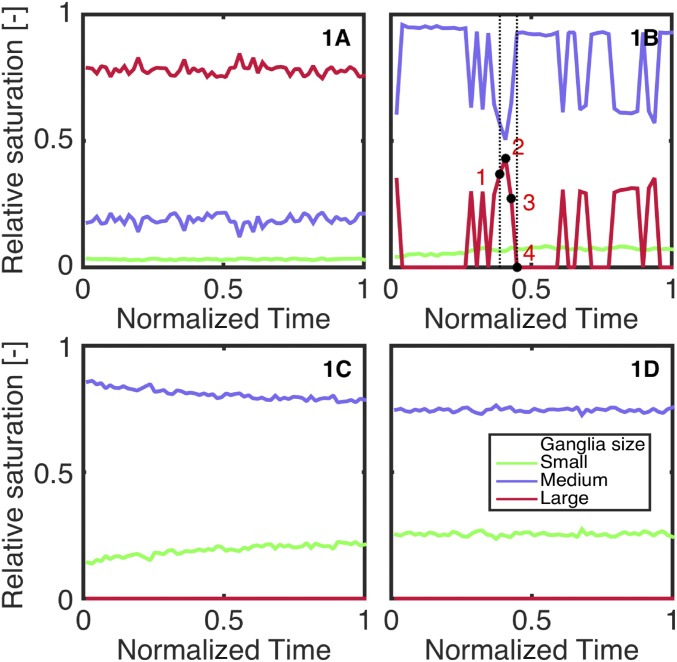
The total saturation throughout each experimental stage remained approximately constant, at a value close to the residual nonwetting phase saturation during imbibition, as measured on larger core samples (24). However, the amount contributed by the different ganglia populations changed with both time and flow rate (Figs. 2 and 3). All of the experiments contained medium and small ganglia, whereas the large ganglia are present only at low flow rates (experiments 1A, 1B, and 2A). As the flow rate rises, the proportion of small and medium ganglia increases, and the proportion of large ganglia decreases.
Fig. 2.
Interaction between ganglia populations. Plots show the relative saturation of small (green), medium (blue), and large (pink) N2 ganglia for experiments 1A to 1D.
Fig. 3.
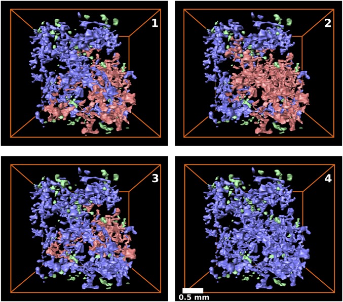
Interaction between ganglia populations. Volume renderings of ganglia from experiment 1B are shown, corresponding to the numbers in red on Fig. 2.
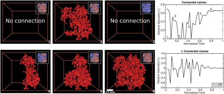
Large ganglia that are connected across the field of view are only observed for the lowest flow rate experiments (1A and 2A). However, the connected pathway is not stable and varies in both volume and position over time. Changes in connected pathway volume do not correspond to a change in total N2 saturation, but are the result of splitting the original connected ganglion into two separate large ganglia, or multiple medium ganglia (Fig. 4). Parts of the connected pathway repeatedly disconnect and reconnect, changing the position of the connected pathway in the pore space.
Fig. 4.
Volume of N2 instantaneously connected from inlet to outlet. In graphs, connected volume of N2 as a percent of total N2 saturation and the relative change in connected volume with time are plotted for experiment 2A. Images show volume rendering of N2 for experiment 2A (numbers 1 to 8). The connected volume of N2 is shown in red. (Insets) Ganglia split by size: small (green), medium (blue), and large (pink) ganglia. Flow is from top to bottom.
The pathway stability can be described in terms of the number of disconnection events that take place between each time step. A decrease in volume of the connected pathway requires a section to become disconnected, whereas an increase requires a connection with a neighboring ganglion to be made. Increasing the flow rate, or capillary number, results in more disconnection and reconnection events, and the pathway has an increasingly dynamic connectivity.
This dynamic connectivity also occurs in experiments without connected pathways, through the interaction between the ganglia populations (Fig. 2). At very low (experiment 1A) or high (experiments 1C and 1D) flow rates, the proportions of small, medium, and large ganglia stay constant over time. The volume of fluid transported through the pore space during the acquisition of a single image is greater than the total pore volume of the imaged core. Thus, the interfaces between ganglia in the pore space must change for the nonwetting phase to flow. Rearrangement of interfaces means the change in the number of ganglia could be due to the transport of individual ganglia wholesale through the pore space or due to the same dynamic connectivity behavior seen in the connected pathways, in which connections open briefly to create a pathway for fluid migration from one pore to another.
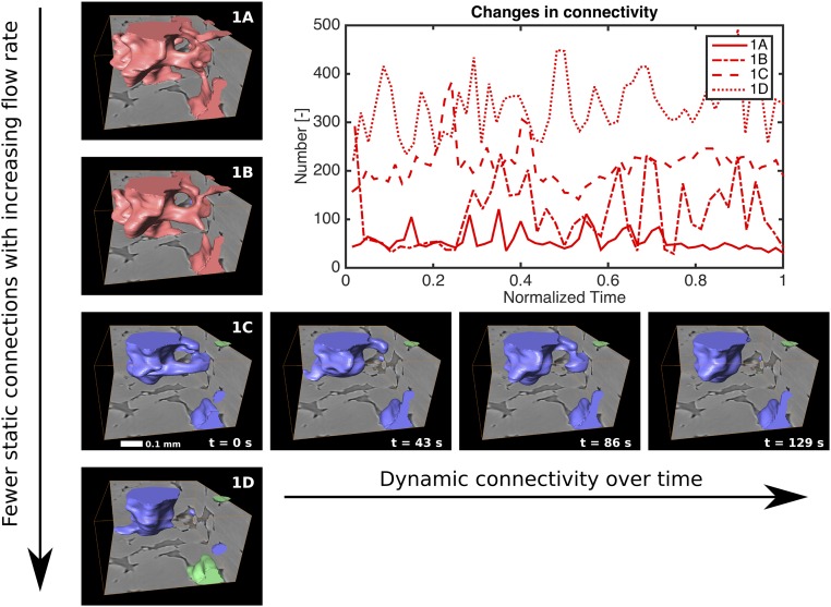
In the time sequence images shown in Fig. 3 (see also Movies S1–S9), individual ganglia moving progressively through the pore space cannot be identified. Instead, the positions of ganglia appear to be static, with some of the connectivity changing between neighboring ganglia. This change in connectivity is illustrated in the subvolume time sequence in Fig. 5. We observe that interaction between ganglia populations is the result of dynamic connectivity in the pore throats, whereas the pore bodies remain filled throughout.
Fig. 5.
Change in connectivity with flow rate and time. Volume renderings of N2 ganglia, colored by size, in a 720 720 360 m subvolume are shown for experiments 1A to 1D. Four consecutive time steps are shown for experiment 1C, illustrating two continuously filled pores and several transient branching connections. Also shown is the number of connections through pore throats in the whole imaged volume versus time. The volume of N2 shown in the images is connected both inside and outside the subvolume.
Dynamic Connectivity: A Single Flow Regime
We estimate that the transition from experiments containing some intermittent connected pathways to experiments containing no connected pathways occurs at critical wetting and critical nonwetting capillary numbers, and (Fig. 6). These are two to three orders of magnitude smaller than the transition identified in beadpack experiments (7); this is likely due to the difference in pore structure between beadpacks and the sandstone used in this study.
Fig. 6.
The arrangement of N2 (as transient connected pathways or as disconnected ganglia) is shown as a function of wetting and nonwetting phase capillary numbers for experiments 1A to 1D and 2A to 2C. We estimate that no connected pathways form above Caw,crit = 4.5 × 10⁻⁶ and Canw,crit = 8.5 × 10⁻⁸.
However, the dynamic connectivity shown is different from that assumed in the traditional conceptual picture of two-phase flow. Instead of a transition from connected pathways to the advection of discrete ganglia, we see transport of the nonwetting phase through pathways that are largely fixed, with some connections that periodically open and close. This novel flow behavior is separate from that reported by Datta et al. (7, 10), specifically, that the ganglia do not flow but instead rearrange their connectivity between filled pores. As capillary number increases, the frequency of connection and disconnection increases, and thus no connected pathway is ever observed.
Fundamentally, steady-state fluid displacement is controlled by an energy balance (25). Work is done to inject fluids: The power per unit volume expended through fluid movement for either phase is approximately given by , where is the effective permeability in multiphase flow and is the total Darcy velocity (26). The surface energy of the interface between the wetting and nonwetting phases per unit volume is ∼, where is a characteristic pore size. The time taken to provide sufficient energy to create the fluid interfaces is roughly . As there is no net displacement in the experiments, fluctuations in the position of the interfaces eventually dissipate the surface energy as heat. For an order of magnitude estimate, we consider m2, m, and m⋅s−1, with the brine viscosity corresponding to the lowest flow rate experiment in Table 1 (16). We find a timescale for interface creation of s or around 20 min. Thus, between two successive scans (43 s), there is sufficient energy provided by the injection to alter the fluid configuration in only around 3% or the pores, or 160 elements in a scan volume encompassing ∼5,000 pores. Our observations show that this leads to connected flow paths that are only sometimes stable across successive scans. However, at the highest flow rates studied, a 50-fold increase in , or a 2,500-fold change in energy, allows rearrangement in all of the pores between scans, leading to a much more dynamic flow pattern.
Reconciling Pore-Scale Flow Mechanisms with Continuum-Scale Properties
The dynamic connection and disconnection we have described is a previously unidentified type of ganglion dynamics. Although, instantaneously, we observe discrete ganglia, they are arranged in a pathway. This pathway is comparable to a road network with traffic lights. The flow of cars through the network can be stopped by a red traffic light, blocking a junction for a short time. When the light turns green—when the local energy balance favors movement again—the flow continues down the same road. On the pore scale, this stop and start process appears very different from the continuous pathway flow originally used to justify the extension of Darcy’s law to multiple fluid phases. Primary drainage in water-wet rocks is accurately modeled by pore-scale simulations (3). At the large scale, although the N2 is instantaneously arranged in separate ganglia, the behavior overall is that of a continuous pathway. Thus, when we make continuum-scale measurements such as relative permeability, we measure flow through the entire road network, not the stop and start of an individual car. The conductance of a phase is governed by the entire volume that it occupies, even intermittently, with a correction for the fraction of time that it occupies each pore.
There have been suggestions of dynamic connectivity in some of the earliest observations of two-phase flow in 2D. Chatenever and Calhoun (5) observed channel flow in a single layer of glass beads and noted that “In the case of temporary flow disturbances the flow channels exhibited an elasticity whereby they tended to resume almost their exact starting configurations with the reestablishment of the original steady conditions." In a recent 3D observation, Datta et al. (7) noted that “Intriguingly… sections of this connected 3D pathway intermittently break up into discrete ganglia, several pores in size - the observed break up process occurs irregularly, punctuated by intervals of continuous flow." It is likely that both these observations are the same disconnection and reconnection behavior observed in the pore-scale experiments presented here.
Conclusions
We have performed coinjection microcore floods using N2 and brine to investigate two-phase steady-state flow behavior at reservoir conditions and have identified a type of flow behavior we term “dynamic connectivity.” Connected flow paths of N2 exist only during low capillary number flow, but are not stable, interacting strongly with the ganglia population in the pore space. At the lowest capillary numbers used, there is sufficient power to reorganize fluid interfaces in up to 3% of the pores over the timescale of observation. This reorganization means connected flow pathways are only stable over tens to hundreds of seconds. The work input increases quadratically with flow rate such that the highest capillary numbers used provide sufficient power for dynamic connectivity to be observed in many of the pores. This intermittency is likely to be initiated by changes in local capillary pressure as fluid interfaces advance. These pressure changes can drive rapid movement and rearrangement of the fluid phases even in a steady-state flow.
Materials and Methods
Core floods were performed with 1.5 mol potassium iodide (KI) brine as the wetting phase and N2 as the nonwetting phase at 10 MPa and 50 °C. Under these conditions, the fluid viscosities were = 642.2 and = 20.8 , and the interfacial tension was 64 mN (27–30). The viscosity ratio of 31:1 used here is typical of gas/oil ratios for during gas injection (31). The viscosity ratio for CO2 injection in saline aquifers is typically 13:1 (32). The capillary number of observations, , ranged from those applicable to subsurface flows () to high values at which advective ganglia transport has been previously observed (7). Equal reservoir-condition volumes of brine and N2 were injected at a constant rate into a Bentheimer sandstone composite microcore composed of four short cores with a total length of 4 cm and each with a diameter of 4 mm. The core sample was contained in X-ray transparent core holder with a confining pressure of 2 MPa over the fluid pressure. The sample was imaged during fluid flow at the Diamond Lightsource Synchrotron. The 3D images with a voxel size of 3.6 m were acquired every 43 s to create a time series. The sample had a porosity of 0.19 and a pore volume of 0.0075 mL, calculated from images of the dry and brine-filled rock. Detailed methods are provided in Supporting Information.
Time Sequence Videos
Time sequence videos of the connected pathways, ganglia populations and subvolumes are provided for experiments 1A to 1D (Movies S1–S9). Ganglia are colored according to size, where large ganglia connected between inlet and outlet are red, large ganglia not connected to both outlets are pink, medium ganglia are blue, and small ganglia are green. Ganglia size definitions are given in Table S1.
Flow Apparatus
Pore-scale steady-state, two-phase coinjection experiments were performed in a purpose-built high-pressure high-temperature single-pass flow rig. A single-syringe pump for N2 and a single-syringe pump for brine (model 500D; Teledyne Isco) were used to coinject fluids (Fig. S1). Brine and N2 were injected into a single line, which delivered the fluids to a core holder. A back-pressure syringe pump (model 500D; Teledyne Isco) on the outlet side of the core was used to maintain the system pressure and collect the fluids once they passed through the core. A confining syringe pump (model 100DX; Teledyne Isco) applied an overburden of 2 MPa over the fluid pressure to the core. The pumps were constructed from a corrosion-resistant alloy (HC276 Hastelloy), and the flow lines were composed of high-pressure flexible polyether ether ketone tubing (Kinesis). The core and confining fluid were heated using a Kapton insulated heating mat (Omega Engineering) wrapped around the outside of the core holder and controlled via a thermocouple inserted into the confining fluid.
The core holder was constructed from carbon fiber (Airbourne Composites). Four sandstone core samples of 4-mm diameter and 8- to 12-mm length were placed in series, wrapped in aluminum foil, and then placed inside a fluoropolymer elastomer (Viton) sleeve. The sleeve was attached to metal fittings connecting the core to the inlet and outlet flow lines, and then the thermocouple was placed against the Viton sleeve, wrapped again in aluminum foil to keep the thermocouple in place and positioned inside the core holder. The core holder was attached to the rotation stage in a vertical orientation with the inlet at the top and outlet at the bottom. The tubing was arranged over a metal support such that the coinjection line was positioned vertically above the core and would not cause any lateral stress on the core holder during rotation.
The dead volume of the core holder was an order of magnitude larger than the pore volume of a single microcore. During single-phase flow, this dead volume is simply filled with the injected fluid as a continuous phase. However, during two-phase flow, the dead volume may be filled with one or both of the injected fluids, and, depending on the flow rate and tubing diameter, slugs of either fluid may sweep through the core (33), creating alternating drainage and imbibition, rather than both fluids entering the core concurrently as a true two-phase flow. To remove the possibility of slug flow, a diffuser was placed at the inlet. The diffuser was composed of three microcores of the same sandstone as the experimental core, creating a composite core 41 mm in length (diffuser length = 30 mm, experimental core length = 11 mm). Even if slugs entered the first core of the diffuser, by the time the fluids reached the final core, they were dispersed throughout the pore space and moving together; this was confirmed by visually examining a time series of 2D projections of the middle cores before starting the 3D imaging.
Image Acquisition
The polychromatic light of the I13 beamline at Diamond Light Source synchrotron in Didcot, UK, was used to image the core. The energy of the “Pink Beam” ranges from 8 KeV to 30 KeV. The low-energy X-rays were filtered out using 2 mm of aluminum and 0.1 mm of gold. Without the filters, the low-energy X-rays are absorbed by the sample as heat. The detector was composed of a 250-m-thick CdWO4 (cadmium tungstate) scintillator with a 1.25 objective lens and a PCO.EDGE sCMOS (scientific complementary metal-oxide-semiconductor) image sensor camera (20, 22).
Images were acquired using 1,200 projections with exposure time of 0.02 s. The total acquisition time for each image was 43 s: 23 s to take the projections and around 20 s to transfer the data from camera to computer and rotate the sample back to the starting position. The number of projections was chosen so as to optimize the resolution of the final images without significantly increasing the acquisition time. A large number of projections provides more information for reconstruction, resulting in a higher signal-to-noise ratio in the reconstructed images. However, the scan acquisition time is proportional to the number of projections used. Because the processes we imaged are dynamic, and fluid continues to flow during acquisition, the resultant images are averages rather than snapshots, with some interfaces blurring during the scan. It is not possible to image individual jumps in interface position in any available synchrotron, as this process occurs within a millisecond (15).
Consecutive images were taken over 28 min to 45 min during two-phase coinjection, providing datasets of 40 to 63 scans that could be stacked to show the step-by-step dynamic flow processes at a particular flow rate. Images were reconstructed using a filtered back-projection algorithm (34–36). The centers of reconstruction were found for the first and last image in each sequence, and a linear interpolation between the two was used to reconstruct each image to account for any drift in sample position between consecutive images. The field of view was mm, giving a reconstructed image of voxels. These images underwent a binning procedure to improve the signal to noise ratio and were cropped, giving a final image size of voxels with a size of 3.6 m.
Choice of Wetting and Nonwetting Fluids
Experimental fluids were chosen to represent the fluid properties of CO2 and brine in a reservoir, but also to optimize the contrast between phases and reduce any experimental artifacts. The low-energy part of the Pink Beam energy spectrum is absorbed by the core holder as heat. Although the beam was filtered, it is still likely that, over the course of an experiment (3 h to 4 h), there would be an appreciable increase in temperature in the core. If using CO2 and CO2-saturated brine, this would likely result in CO2 exsolving from solution over the duration of an experiment, creating extra bubbles of CO2 that would interfere with the interpretation of the flow processes being imaged. N2 was used as an analogue to CO2. The solubility of N2 in brine is around one thousandth that of CO2 in brine and thus will not be influenced by temperature fluctuations in the apparatus (37, 38). The density of N2 also changes little with heating.
The experimental brine was chosen to have the greatest contrast in X-ray attenuation with N2, as this would lead to a larger separation of the grayscale values of the two fluids in the reconstructed images, aiding their segmentation. Both NaCl brine and deionized water have similar linear attenuation coefficients to N2, meaning the contrast between the two is low, and thus the grayscale values of N2 and brine in the reconstructed images would overlap. KI brine has a similar linear attenuation coefficient to quartz, but a large contrast with N2. Thus, a 25 wt% (1.5 molkg−1) salinity of KI brine was chosen, as this resulted in the brine having a higher attenuation factor than N2 but lower than the sandstone sample, while still having a realistic reservoir brine salinity.
Image Processing
After the initial reconstruction and binning, all image processing was performed using commercial software (Avizo 9.1, www.vsg3d.com). Reconstructed images must undergo a number of processing steps before N2 can be segmented (Fig. S2). First, the raw images are filtered using a nonlocal means edge-preserving filter (39) to increase the signal to noise ratio and smooth the grayscale value of the images. All experimental scans were registered to a reference brine scan using normalized mutual information and were resampled using the robust Lanczos method (40). Registering and resampling meant the voxels were aligned between all images, and thus image arithmetic operations could be performed. Histograms of the grayscale in each image were compared to ensure that the linear attenuation coefficient did not vary between scans. The resampled data were then subtracted from the reference brine scan to highlight the position of N2. These difference images were filtered using a nonlocal means algorithm to increase signal to noise. The reference scan and filtered difference images were then segmented using a watershed algorithm (41, 42).
A key image processing step is the segmentation of the grayscale image into a labeled image denoting rock grains, brine, and N2. This step is achieved by manually thresholding the image and using a watershed segmentation algorithm to grow the seeds of each identified phase. Watershed segmentation (42) puts seeds at the local minima of a hypothetical 3D topography defined by the grayscale intensity of the images.
The seed values were selected manually using a 2D histogram of both the grayscale and the grayscale gradient images (43). Seed values were chosen in regions with a low gradient in grayscale, where a phase could be clearly identified (Fig. S3). The seeds were then grown up to the maxima in grayscale intensity toward areas of high grayscale gradient, which define the interfaces between phases. Although manual identification of seeds is prone to operator bias, automatic thresholding techniques have been found to be inconsistent in two-phase segmentation when dealing with multiple datasets (41), let alone three-phase segmentation in hundreds of separate images as is the case for the dataset presented here.
Fig. S3 shows grayscale intensity profiles across images that have undergone different processing steps. The brine and quartz have similar grayscale values, so a difference image between the brine-filled sample and the experimental sample was used to segment N2, whereas a dry scan of the rock with the pore space containing only air was used to segment the rock grains. Segmented images containing regions labeled as brine, N2, and rock grains were produced by adding separate labeled images for each phase. The “axis connectivity” module in Avizo was used to assess whether any connected pathways of N2 existed across the imaged section of the core.
Classification of Ganglia
Ganglia below 5,000 voxels in volume were discounted from the analysis, as these are much smaller than the mean pore diameter and contributed <2% of the total N2 volume. Volume cutoffs and the equivalent number of pores are given in Table S1.
Supplementary Material
Acknowledgments
The authors acknowledge Dr. Christoph Rau and Dr. Mirian Garcia-Fernandez for their assistance. We also thank the additional members of the experimental team from Imperial College who participated in the experiments. In particular, we recognize the contributions of Dr. Branko Bjeljic and Dr. Kamal Singh. We gratefully acknowledge Diamond Light Source for access to beamline I13, and funding from Qatar Petroleum, Shell, and the Qatar Science and Technology Park. C.A.R. was funded by Engineering and Physical Sciences Research Council Grant 1304506.
Footnotes
The authors declare no conflict of interest.
This article is a PNAS Direct Submission.
This article contains supporting information online at www.pnas.org/lookup/suppl/doi:10.1073/pnas.1702834114/-/DCSupplemental.
References
- 1.Muskat M, Meres MW. The flow of heterogeneous fluids through porous media. Physics. 1936;7:346–363. [Google Scholar]
- 2.Dullien FAL. Porous Media: Fluid Transport and Pore Structure. Academic; New York: 1991. [Google Scholar]
- 3.Blunt MJ. Multiphase Flow in Permeable Media: A Pore-Scale Perspective. Cambridge Univ Press; Cambridge, UK: 2017. [Google Scholar]
- 4.Lenormand R, Zarcone C, Sarr A. Mechanisms of the displacement of one fluid by another in a network of capillary ducts. J Fluid Mech. 1983;135:337–353. [Google Scholar]
- 5.Chatenever A, Calhoun JC. Visual examinations of fluid behaviour in porous media - Part I. J Pet Technol. 1952;4:149–156. [Google Scholar]
- 6.Scheidegger AE. The Physics of Flow Through Porous Media. University of Toronto Press; Toronto: 1958. [Google Scholar]
- 7.Datta SS, Dupin JB, Weitz DA. Fluid breakup during simultaneous two-phase flow through a three-dimensional porous medium. Phys Fluid. 2014;26:062004. [Google Scholar]
- 8.Taber JJ. Dynamic and static forces required to remove a discontinuous oil phase from porous media containing both oil and water. Soc Pet Eng J. 1969;9:3–12. [Google Scholar]
- 9.Avraam DG, Payatakes AC. Flow regimes and relative permeabilities during steady-state two-phase flow in porous media. J Fluid Mech. 1995;293:207–236. [Google Scholar]
- 10.Datta SS, Ramakrishnan T, Weitz DA. Mobilization of a trapped non-wetting fluid from a three-dimensional porous medium. Phys Fluid. 2014;26:022002. [Google Scholar]
- 11.Tallakstad KT, et al. Steady-state, simultaneous two-phase flow in porous media: An experimental study. Phys Rev E Stat Nonlin Soft Matter Phys. 2009;80:036308. doi: 10.1103/PhysRevE.80.036308. [DOI] [PubMed] [Google Scholar]
- 12.Erpelding M, et al. History independence of steady state in simultaneous two-phase flow through two-dimensional porous media. Phys Rev E Stat Nonlin Soft Matter Phys. 2013;88:053004. doi: 10.1103/PhysRevE.88.053004. [DOI] [PubMed] [Google Scholar]
- 13.Rassi EM, Codd SL, Seymour JD. Nuclear magnetic resonance characterization of the stationary dynamics of partially saturated media during steady-state infiltration flow. New J Phys. 2011;13:015007. [Google Scholar]
- 14.Zhao B, MacMinn C, Juanes R. Wettability control on multiphase flow in patterned microfluidics. Proc Natl Acad Sci USA. 2016;113:10251–10256. doi: 10.1073/pnas.1603387113. [DOI] [PMC free article] [PubMed] [Google Scholar]
- 15.Berg S, et al. Real-time 3D imaging of Haines jumps in porous media flow. Proc Natl Acad Sci USA. 2013;110:3755–3759. doi: 10.1073/pnas.1221373110. [DOI] [PMC free article] [PubMed] [Google Scholar]
- 16.Blunt MJ, et al. Pore-scale imaging and modelling. Adv Water Resour. 2013;51:197–216. [Google Scholar]
- 17.Wildenschild D, Sheppard AP. X-ray imaging and analysis techniques for quantifying pore-scale structure and processes in subsurface porous medium systems. Adv Water Resour. 2013;51:217–246. [Google Scholar]
- 18.Andrew M, Bijeljic B, Blunt MJ. Pore-scale imaging of trapped supercritical carbon dioxide in sandstones and carbonates. Int J Greenhouse Gas Control. 2014;22:1–14. [Google Scholar]
- 19.Singh K, Bijeljic B, Blunt MJ. Imaging of oil layers, curvature, and contact angle in a mixed-wet and a water-wet carbonate rock. Water Resour Res. 2016;52:1716–1728. [Google Scholar]
- 20.Andrew M, Menke H, Blunt MJ, Bijeljic B. The imaging of dynamic multiphase fluid flow using synchrotron-based X-ray microtomography at reservoir conditions. Transp Porous Media. 2015;110:1–24. [Google Scholar]
- 21.Rücker M, et al. From connected pathway flow to ganglion dynamics. Geophys Res Lett. 2015;42:3888–3894. [Google Scholar]
- 22.Menke HP, Andrew MG, Blunt MJ, Bijeljic B. Reservoir condition imaging of reactive transport in heterogeneous carbonates using fast synchrotron tomography - Effect of initial pore structure and flow conditions. Chem Geol. 2016;428:15–26. [Google Scholar]
- 23.Pak T, Butler IB, Geiger S, van Dijke MIJ, Sorbie KS. Droplet fragmentation: 3D imaging of a previously unidentified pore-scale process during multiphase flow in porous media. Proc Natl Acad Sci USA. 2015;112:1947–1952. doi: 10.1073/pnas.1420202112. [DOI] [PMC free article] [PubMed] [Google Scholar]
- 24.Reynolds CA, Krevor S. Characterizing flow behavior for gas injection: Relative permeability of CO2-brine and N2-water in heterogeneous rocks. Water Resour Res. 2015;51:9464–9489. [Google Scholar]
- 25.Cueto-Felgueroso L, Juanes R. A discrete-domain description of multiphase flow in porous media: Rugged energy landscapes and the origin of hysteresis. Geophys Res Lett. 2016;43:1615–1622. [Google Scholar]
- 26.Raeini AQ, Blunt MJ, Bijeljic B. Direct simulations of two-phase flow on micro-CT images of porous media and upscaling of pore-scale forces. Adv Water Resour. 2014;74:116–126. [Google Scholar]
- 27.Span R, W LE, Jacobsen RT, Wagner W, Yokozeki A. A reference equation of state for the thermodynamic properties of nitrogen for temperatures from 63.151 to 1000 K and pressures to 2200 MPa. J Phys Chem Ref Data. 2000;29:1361–1433. [Google Scholar]
- 28.Lemmon EW, McLinder MO, Friend DG. In: Thermophysical Properties of Fluid Systems. NIST Chemistry WebBook: NIST Standard Reference Database. Mallard PJ, W G, editors. vol 69 Natl Inst Standards Technol; Gaithersburg: 2016. [Google Scholar]
- 29.Yan W, Zhao GY, Chen GJ, Guo TM. Interfacial tension of (methane+ nitrogen)+ water and (carbon dioxide+ nitrogen)+ water systems. J Chem Eng Data. 2001;46:1544–1548. [Google Scholar]
- 30.Kestin J, Khalifa HE, Correia RJ. Tables of the dynamic and kinematic viscosity of aqueous NaCl solutions in the temperature range 20–150°C and the pressure range 0.1–35 MPa. J Phys Chem Ref Data. 1981;10:71–88. [Google Scholar]
- 31.Christie MA, Muggeridge AH, Barley JJ. 3D simulation of viscous fingering and wag schemes. SPE Reservoir Eng. 1993;8:19–26. [Google Scholar]
- 32.Boait FC, et al. Spatial and temporal evolution of injected co2 at the Sleipner field, North sea. J Geophys Res. 2012;117:B03309. [Google Scholar]
- 33.Taitel Y, Bornea D, Dukler AE. Modelling flow pattern transitions for steady upward gas-liquid flow in vertical tubes. AIChE J. 1980;26:345–354. [Google Scholar]
- 34.Titarenko V, Titarenko S, Withers PJ, De Carlo F, Xiao X. Improved tomographic reconstructions using adaptive time-dependent intensity normalization. J Synchrotron Radiat. 2010;17:689–699. doi: 10.1107/S0909049510024908. [DOI] [PMC free article] [PubMed] [Google Scholar]
- 35.Kyrieleis A, Ibison M, Titarenko V, Withers PJ. Image stitching strategies for tomographic imaging of large objects at high resolution at synchrotron sources. Nucl Instrum Methods Phys Res A. 2009;607:677–684. [Google Scholar]
- 36.Kyrieleis A, Titarenko V, Ibison M, Connolley T, Withers PJ. Region-of-interest tomography using filtered backprojection: Assessing the practical limits. J Microsc. 2011;241:69–82. doi: 10.1111/j.1365-2818.2010.03408.x. [DOI] [PubMed] [Google Scholar]
- 37.Søreide I, Whitson CH. Peng-Robinson predictions for hydrocarbons, CO2, N2, and H2S with pure water and NaCI brine. Fluid Phase Equilib. 1992;77:217–240. [Google Scholar]
- 38.O’Sullivan TD, Smith NO. Solubility and partial molar volume of nitrogen and methane in water and in aqueous sodium chloride from 50 to 125°C and 100 to 600 atm. J Phys Chem. 1970;74:1460–1466. [Google Scholar]
- 39.Buades A, Coll B, Morel JM. Nonlocal image and movie denoising. Int J Comput Vis. 2008;76:123–139. [Google Scholar]
- 40.Lanczos C. An iteration method for the solution of the eigenvalue problem of linear differential and integral operators. J Res Natl Bur Stand. 1950;45:255–282. [Google Scholar]
- 41.Schlüter S, Sheppard A, Brown K, Wildenschild D. Image processing of multiphase images obtained via X-ray microtomography: A review. Water Resour Res. 2014;50:3615–3639. [Google Scholar]
- 42.Beucher S. The watershed Transformation applied to image segmentation. Scanning Microsc Int Suppl. 1991;6:299–314. [Google Scholar]
- 43.Jones AC, et al. Assessment of bone ingrowth into porous biomaterials using MICRO-CT. Biomaterials. 2007;28:2491–2504. doi: 10.1016/j.biomaterials.2007.01.046. [DOI] [PubMed] [Google Scholar]
Associated Data
This section collects any data citations, data availability statements, or supplementary materials included in this article.


