

Abstract
OBJECTIVE
Preoperative magnetic resonance images (pMR) are typically coregistered to provide intraoperative navigation, the accuracy of which can be significantly compromised by brain deformation. In this study, the authors generated updated MR images (uMR) in the operating room (OR) to compensate for brain shift due to dural opening, and evaluated the accuracy and computational efficiency of the process.
METHODS
In 20 open cranial neurosurgical cases, a pair of intraoperative stereovision (iSV) images was acquired after dural opening to reconstruct a 3D profile of the exposed cortical surface. The iSV surface was registered with pMR to detect cortical displacements that were assimilated by a biomechanical model to estimate whole-brain nonrigid deformation and produce uMR in the OR. The uMR views were displayed on a commercial navigation system and compared side by side with the corresponding coregistered pMR. A tracked stylus was used to acquire coordinate locations of features on the cortical surface that served as independent positions for calculating target registration errors (TREs) for the coregistered uMR and pMR image volumes.
RESULTS
The uMR views were visually more accurate and well aligned with the iSV surface in terms of both geometry and texture compared with pMR where misalignment was evident. The average misfit between model estimates and measured displacements was 1.80 ± 0.35 mm, compared with the average initial misfit of 7.10 ± 2.78 mm between iSV and pMR, and the average TRE was 1.60 ± 0.43 mm across the 20 patients in the uMR image volume, compared with 7.31 ± 2.82 mm on average in the pMR cases. The iSV also proved to be accurate with an average error of 1.20 ± 0.37 mm. The overall computational time required to generate the uMR views was 7–8 minutes.
CONCLUSIONS
This study compensated for brain deformation caused by intraoperative dural opening using computational model–based assimilation of iSV cortical surface displacements. The uMR proved to be more accurate in terms of model-data misfit and TRE in the 20 patient cases evaluated relative to pMR. The computational time was acceptable (7–8 minutes) and the process caused minimal interruption of surgical workflow.
Keywords: image-guided neurosurgery, brain deformation, FEM model, sparse data, intraoperative stereovision, diagnostic and operative techniques
In image-guided neurosurgery, preoperative magnetic resonance images (pMR) are typically rigidly aligned with the patient’s head in the operating room (OR) using fiducial-based registration.1 Commercial image-guided systems provide real-time information on where surgical instruments (e.g., a stylus probe, an operating microscope, or an ultrasound scan head) are located relative to the coregistered preoperative scans. The accuracy of this form of navigation is typically between 2 and 5 mm10 when measured by fiducial registration error (FRE), although its validity relies on maintaining a rigid relationship between the patient’s brain tissue and pMR image data. Unfortunately, registration accuracy degrades during a procedure because of loss of blood and CSF, gravity, intracranial pressure, use of medications, tissue retraction/resection, etc. Thus, updating the navigational information intraoperatively to compensate for brain shift is needed to restore the accuracy of image coregistration and thereby improve image guidance, a technology that is shown to be associated with extent of resection, surgical outcomes, and patient survival.2,17,19,22
The use of an intraoperative magnetic resonance imaging scanner (iMR) appears to be the ideal method of augmenting conventional pMR neuronavigation, but the approach is costly, relatively time consuming, and not widely available. As a result, iMR is deployed primarily at larger academic medical centers, and even then, mostly at the presumed end of tumor resection to identify residual disease that could still be safely removed. Intraoperative ultrasound (iUS) is a low-cost, more facile alternative that can be coregistered to the surgical field and provides real-time image surveys as aids in guiding the surgeon during a procedure. Unfortunately, iUS has poor soft-tissue contrast and can be difficult to interpret relative to pMR. Thus, even though coregistered iUS is useful and practical, it is an incomplete solution to the problem of coregistration inaccuracies caused by brain shift.
We (and others)3,5,8,9,11,16,18,20,23,24,28 have developed image-guidance updating frameworks formulated around computational model–based assimilation of brain shift measurement data acquired intraoperatively with minimally disruptive imaging tools. The accuracy and performance of these approaches have been evaluated in clinical cases,16,21,24,28 but most analyses have been retrospective to surgery, and updated images have not routinely been generated in the OR. In recent work by Sun et al.,24 a brain shift compensation system involving intraoperative laser range scanning was described to perform brain shift correction intraoperatively. Its processing time was evaluated and found to require approximately 11–13 minutes to complete. Accuracy of the resulting updated magnetic resonance (uMR) images was reported in terms of percentage of shift corrected (i.e., the ratio between shift corrected and shift measured), but the updates were not evaluated with independent measurements of the coordinate locations of features in the surgical field whose corresponding positions in the coregistered (updated) image volume could also be found. The study focused on brain shift between postdural opening and postresection, whereas brain shift often occurs immediately after dural opening and correction is desirable even before resection begins. In previous work,7 we described a method to measure 3D brain shift due to dural opening by registering intraoperative stereovision (iSV) surfaces with pMR, but we used the data to generate uMR images retrospective to the surgical case and did not assess the target registration error (TRE) of the uMR results.
In this study, we present results from our image updating system in which uMRs were produced in the OR immediately after dural opening. Furthermore, the uMR views were displayed on a commercial navigation system for the first time and compared intraoperatively with the corresponding pMR image through side-by-side visualization. We assess the accuracy of uMR relative to pMR in terms of the TRE found by acquiring independent position measurements of cortical surface features with a tracked stylus. We also evaluate the performance of the image updating system in terms of the total computational time required to generate and display the uMR views.
Methods
Surgical Cases and Procedure
Twenty patients undergoing open cranial procedures were evaluated intraoperatively at Dartmouth-Hitchcock Medical Center. The study was approved by the Institutional Review Board at Dartmouth. Criteria for inclusion were availability of: 1) T1-weighted contrast-enhanced MRI head scans acquired prior to surgery and used for intraoperative image guidance; and 2) common features, such as blood vessels, visible on both the exposed cortical surface of the brain and MR scans. Patient sex, age, type of lesion, and location and size of craniotomy are summarized in Table 1.
TABLE 1.
Summary of patient information
| Case No. | Age (yrs), Sex | Lesion | Location | Craniotomy Size (cm) | Registration Accuracy (mm) |
|---|---|---|---|---|---|
| 1 | 60, M | Glioblastoma | Lt temporal | 4.6 × 3.6 | 1.49 |
| 2 | 83, M | Glioblastoma | Rt parietal | 4.4 × 4.0 | 2.32 |
| 3 | 61, F | Meningioma | Rt parietal | 7.3 × 5.3 | 2.84 |
| 4 | 68, F | Metastatic carcinoma | Rt frontal | 4.9 × 4.5 | 1.67 |
| 5 | 39, F | Arteriovenous malformation | Rt frontal | 4.9 × 4.8 | 1.72 |
| 6 | 69, M | Glioblastoma | Lt temporal | 4.7 × 3.8 | 1.91 |
| 7 | 62, F | Meningioma | Rt frontal | 10.2 × 3.1 | 0.97 |
| 8 | 35, M | Meningioma | Rt frontal | 4.9 × 4.7 | 1.64 |
| 9 | 78, F | Metastatic carcinoma | Rt frontal | 3.5 × 3.1 | 1.44 |
| 10 | 53, M | Anaplastic astrocytoma | Rt temporal | 4.7 × 3.1 | 1.85 |
| 11 | 61, M | Glioblastoma | Rt temporal | 6.0 × 3.4 | 1.47 |
| 12 | 58, M | Glioblastoma | Rt parietal | 5.8 × 4.0 | 1.99 |
| 13 | 78, F | Metastatic carcinoma | Rt temporal | 4.1 × 3.4 | 1.96 |
| 14 | 80, F | Glioblastoma | Rt temporal | 6.9 × 6.6 | 1.97 |
| 15 | 35, M | Fibrous meningioma | Lt parietal | 8.2 × 5.7 | 1.16 |
| 16 | 63, F | Glioblastoma | Rt parietal | 10.1 × 5.8 | 2.12 |
| 17 | 65, M | Glioblastoma | Lt frontal | 6.4 × 3.6 | 1.50 |
| 18 | 61, M | Anaplastic mixed oligoastrocytoma | Lt parietal | 4.2 × 3.5 | 2.35 |
| 19 | 44, F | Meningioma | Lt frontal | 2.3 × 2.2 | 1.52 |
| 20 | 68, F | Anaplastic oligodendroglioma | Rt frontal | 2.8 × 2.5 | 1.65 |
The T1-weighted contrast-enhanced pMR head scans were acquired before surgery (scan size 256 × 256, 120–144 slices, voxel size 0.9375 × 0.9375 × 1.5 mm) as part of standard of care. At the time of surgery, fiducial-based patient registration using pMR was performed on a commercial navigation system (StealthStation S7, Medtronic) to provide intraoperative navigation. The registration error metric provided by the navigation system at the time of surgery was 1.78 mm on average and is reported in Table 1. An operating microscope (OPMI Pentero, Carl Zeiss Surgical GmbH) was connected to the navigation unit for optical tracking. An iSV system that consisted of 2 charge-coupled device cameras (Flea2, Point Gray Research, Inc.) was attached to one of the binocular ports on the microscope and was precalibrated for 3D surgical surface reconstruction. The iSV system was draped together with the microscope at the beginning of surgery and remained within the sterile bag throughout the case to maintain sterility of the surgical field. After dural opening, an iSV image pair (1024 × 768 pixels) of the surgical field was acquired to produce a texture intensity–encoded 3D map of the cortical surface that was coregistered with MRI using tracking data obtained from the navigation system through the Medtronic Stealth-Link communications framework. The technical details of stereovision calibration and reconstruction have been published previously.13,14,23,25 A sterilized stylus tracked by the navigation system was used to obtain independent measurements of locations of features (such as arterial and venous blood vessel junctions) on the exposed cortical surface for accuracy assessment.
Model-Based MR Image Updating Procedure
The flowchart in Fig. 1 summarizes the model-based MR image updating process. Specifically, prior to the start of surgery, a subject-specific tetrahedral mesh was created based on the segmented brain.27 After dural opening, iSV images were acquired and the reconstructed iSV surface was registered with pMR to extract surface displacement data as described in detail previously7 and illustrated in Fig. 2.
FIG. 1.

Flowchart of the model-based image updating process. FEM = finite element method.
FIG. 2.
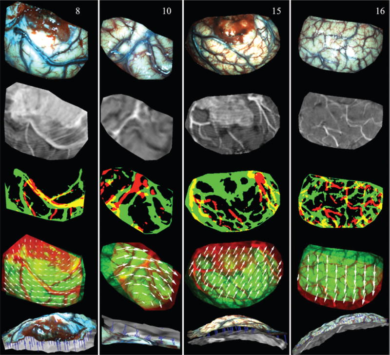
Illustration of surface registration between iSV and pMR for Cases 8, 10, 15, and 16 (columns left to right). The first and second rows show the iSV texture maps and pMR-encoded images, respectively. Thresholded binary iSV (green) and pMR (red) images are overlaid in the third row, and misalignment indicates lateral shift of the cortical surface. The fourth row presents an overlay of iSV (green) and pMR (red) images after registration, in which the 2D displacements appear as white vectors. The fifth row shows an overlay of the iSV (colored) and pMR (grayscale) brain surfaces where the extracted 3D displacements appear as blue vectors (pointing from pMR to iSV). Figure is available in color online only.
Briefly, the iSV surface was projected along the average direction normal to the surface onto the MR brain surface, and a pMR-encoded texture map was generated by replacing iSV pixel intensities with MR values interpolated at the projected locations from pMR. Then, the iSV- and pMR-encoded texture maps were automatically thresholded using Otsu’s method to produce two binary images of their dominant features, and a sum-of-squared-intensity difference rigid registration was applied to compensate for global lateral shift of the cortical surface. The rigidly aligned pMR-encoded image was then divided into small blocks with an average size of 100 × 100 pixels (depending on the size of the region of interest), each of which was registered with iSV using mutual information to account for local nonrigid displacements.
Appropriate boundary and interior forcing conditions were assigned to different regions of the brain, as described previously.15 For example, the iSV surface defined the size and location of the craniotomy, and the corresponding skull within this boundary was removed from pMR for deformation modeling. The inner surface of the skull was assumed to be rigid and tissue in contact was constrained to displace only laterally, if at all, whereas tissue within the opened cranial wall was allowed to move freely in any direction. A biomechanical brain deformation model minimized the misfit between sampled local displacements and model estimates. The resulting whole-brain deformation field was then used to deform pMR into the uMR to complete the process.
The uMR was transferred to the StealthStation as a DICOM image series in the same coordinate frame of reference as the pMR. Because uMR and pMR images were already coregistered, they were displayed on the navigation system simultaneously, which allowed the surgeon to compare uMR relative to pMR at the same location and visually validate the uMR results by navigating a surgical instrument (e.g., a stylus probe or the focal point of the microscope) to a known landmark in the surgical field. Figure 3 shows an intraoperative screenshot of the comparison views on the StealthStation, where the top and bottom rows show pMR and uMR, respectively. The operating microscope was focused on the cortical surface of the brain and tracked by the navigation system. The green crosshairs represent the corresponding position in MR image space, which correctly points to the brain surface in uMR but falls on the scalp in pMR. The green contours show boundaries of tumor, which was segmented based on pMR prior to the start of surgery. The large discrepancy between the contour lines and the contrast-enhanced region in uMR indicates that the contours were no longer accurate after dural opening due to brain deformation.
FIG. 3.

Intraoperative screenshot of the comparison views on the StealthStation from Case 16. Upper and lower rows show pMR and uMR, respectively. The green crosshairs represent the corresponding position in MR image space, which correctly points to the brain surface in uMR, but falls on the scalp in pMR. The green contours show boundaries of tumor, which was segmented prior to the start of surgery based on pMR. The large discrepancy between the contour lines and the contrast-enhanced region in uMR indicates that due to brain deformation the contours were no longer accurate after dural opening. Figure is available in color online only.
Data Analysis
We qualitatively assessed the accuracy of uMR by visually comparing it to reconstructed iSV surfaces after dural opening in terms of both geometry and texture. As a quantitative assessment of the accuracy of uMR, we computed the model-data misfit, measured as the root mean square (RMS) error between measured displacements (through surface registration) and model estimates, and compared it against the pMR misfit, i.e., the locally measured 3D displacements between iSV and pMR. We also evaluated the TRE at dominant features on the exposed cortical surface. Specifically, the neurosurgeon (D.W.R.) localized vessel junctions visible on both the exposed cortical surface and the MR-encoded texture map with a sterile stylus probe tracked by the navigation system, and the coordinate positions of these locations were recorded. Then, the same features were identified on both the pMR- and uMR-encoded texture maps, respectively, and their 3D coordinates in MR image space were extracted. TRE was computed as the distance between the tracked stylus positions of these features transformed into MR image space coordinates and their locations in the pMR and uMR image volumes. Figure 4 shows an example from Case 8, in which 3 feature points (vessel junctions) were touched on the cortical surface with a stylus probe (Fig. 4A–C), and the corresponding locations were identified in the uMR-encoded texture map (Fig. 4D).
FIG. 4.
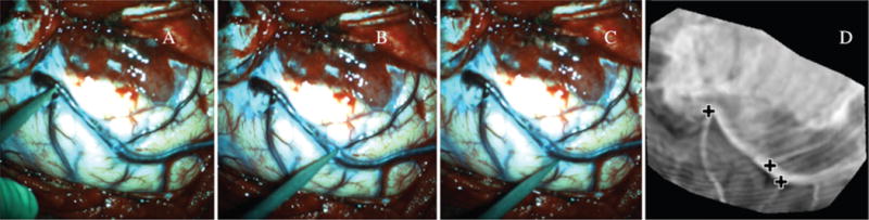
TRE was evaluated by comparing tracked locations of dominant features on the cortical surface against their corresponding positions in uMR. Three feature points (in A–C) were touched with a tracked stylus probe, and manually identified in the uMR-encoded texture map (crosses, D). Figure is available in color online only.
We also assessed the accuracy of the iSV system using the same approach of touching feature points on the cortical surface with the stylus to obtain their locations in the tracking coordinate system and comparing these values to their corresponding positions on the reconstructed iSV surface.
Results
Model-Updated MR Accuracy Evaluation
Figure 5 shows representative 2D slices and 3D views of uMR (second and fourth row, respectively) overlaid with the postdural opening iSV surfaces from Cases 8, 10, 15, and 16 (left to right columns), compared against pMR (first and third row). The favorable alignment between iSV and uMR in the 2D and 3D views indicates that the uMR was more accurate in terms of both geometry and texture, respectively, whereas pMR misalignment is evident.
FIG. 5.

Comparison of pMR and uMR in 2D and 3D views from Cases 8, 10, 15, and 16 (columns left to right). The first and second rows show representative pMR and uMR slices overlaid with iSV (yellow contour lines), respectively, whereas the third and fourth rows present 3D views of the same overlays. Arrows in the 3D views highlight features that align accurately in uMR but poorly in pMR. Figure is available in color online only.
To evaluate the accuracy of uMR quantitatively, we report the uMR misfit for the 20 patients in Table 2 (third column), along with the pMR misfit (second column; mean ± SD). The pMR misfit is the average measured displacement between pMR and iSV, which is essentially the average magnitude of brain surface shift. We also report the direction of cortical shift in terms of its outward/inward movement (“+” and “−” signs, respectively, in Table 2), which was determined by comparing the 3D iSV displacements relative to the normal direction of the original pMR brain surface. Figure 6 shows an example of a contour map of displacement magnitudes decomposed in the normal direction (contour lines highlight magnitudes from +1 mm to +9 mm representing outward shift). The results show that the initial pMR misfit before image updating ranged from 3.02 mm to 11.62 mm with an average of 7.10 mm across the 20 cases. The remaining misfit after image updating was 1.80 ± 0.35 mm on average (range 1.18–2.44 mm), which shows that the image updating process accounted for 71% ± 11% (calculated as [1 – uMR misfit/pMR misfit] × 100%; Table 2) of the brain shift. TRE of pMR and uMR at dominant vessel junctions on the cortical surface are reported in the fifth and sixth columns along with the number of feature points used for accuracy assessment in parentheses. The results show that the average TRE was 1.60 ± 0.43 mm (range 0.72–2.50 mm) for uMR relative to 7.31 ± 2.82 (range 2.67–11.95 mm) for pMR.
TABLE 2.
Summary of coregistered uMR and pMR accuracy in 20 patient cases
| Case No. | Mean pMR Misfit ± SD in mm (movement direction) | uMR Misfit (mm) | % Correction | Mean pMR TRE ± SD in mm (feature points) | Mean uMR TRE ± SD (mm) | Mean iSV error ± SD in mm (feature points) | FRE (mm) | Time (min) |
|---|---|---|---|---|---|---|---|---|
| 1 | 7.35 ± 2.52 (+) | 1.96 | 73 | 8.31 ± 0.58 (2) | 1.40 ± 0.06 | 1.72 ± 0.89 (5) | 2.85 | 5 |
| 2 | 4.97 ± 0.35 (−) | 1.18 | 76 | 4.93 (1)* | 1.26 | 1.77 ± 1.20 (5) | 6.16 | 7 |
| 3 | 5.59 ± 1.74 (+) | 2.44 | 56 | 6.72 ± 1.05 (2) | 1.68 ± 0.98 | 1.48 ± 0.69 (7) | 4.99 | 4 |
| 4 | 4.09 ± 2.15 (+) | 1.67 | 59 | 4.72 ± 1.99 (3) | 1.93 ± 0.46 | 0.88 ± 0.35 (7) | 2.11 | 9 |
| 5 | 4.80 ± 1.29 (−) | 1.89 | 61 | 5.83 ± 1.36 (2) | 1.94 ± 0.34 | 1.07 ± 0.56 (9) | 1.99 | 7 |
| 6 | 9.40 ± 1.96 (+) | 1.80 | 81 | 9.97 ± 1.22 (3) | 1.73 ± 0.14 | 0.70 ± 0.19 (6) | 2.53 | 11 |
| 7 | 10.19 ± 1.88 (+) | 1.37 | 87 | 10.46 ± 3.42 (3) | 1.85 ± 0.72 | 1.16 ± 0.64 (7) | 1.35 | 9 |
| 8 | 6.55 ± 2.37 (+) | 2.39 | 64 | 8.14 ± 2.99 (3) | 2.50 ± 1.89 | 1.64 ± 0.87 (6) | 2.96 | 7 |
| 9 | 3.97 ± 1.25 (+) | 1.70 | 57 | 3.91 (1)* | 0.72 | 0.36 ± 0.13 (5) | 1.92 | 9 |
| 10 | 8.26 ± 1.25 (−) | 1.65 | 80 | 6.78 ± 0.68 (4) | 1.46 ± 0.66 | 1.45 ± 0.25 (5) | 2.32 | 8 |
| 11 | 6.39 ± 1.85 (+) | 1.79 | 72 | 5.95 (1)* | 2.06 | 1.30 ± 0.51 (5) | 1.82 | 8 |
| 12 | 6.23 ± 2.09 (+) | 1.52 | 76 | 5.78 ± 2.23 (2) | 1.67 ± 0.61 | 1.31 ± 0.75 (7) | 3.67 | 6 |
| 13 | 6.04 ± 1.39 (+) | 1.51 | 75 | 6.15 ± 1.02 (2) | 1.59 ± 0.21 | 1.18 ± 1.25 (5) | 2.87 | 8 |
| 14 | 3.95 ± 1.24 (+) | 1.31 | 67 | 4.99 (1)* | 1.19 | 1.22 ± 0.31 (5) | 3.62 | 7 |
| 15 | 11.62 ± 2.12 (+) | 2.18 | 81 | 11.27 ± 0.06 (3) | 1.62 ± 0.22 | 1.03 ± 0.30 (4) | 2.57 | 7 |
| 16 | 10.72 ± 1.11 (+) | 1.93 | 82 | 11.92 ± 0.94 (5) | 1.64 ± 0.25 | 1.31 ± 0.64 (7) | 4.31 | 8 |
| 17 | 9.32 ± 2.26 (+) | 2.05 | 78 | 10.49 ± 2.12 (2) | 1.66 ± 1.40 | 1.36 ± 0.75 (6) | 2.96 | 5 |
| 18 | 12.75 ± 1.99 (+) | 1.96 | 85 | 11.95 ± 0.57 (3) | 0.77 ± 1.06 | 0.83 ± 0.54 (6) | 4.73 | 9 |
| 19 | 3.02 ± 1.08 (−) | 1.56 | 48 | 2.68 ± 0.55 (3) | 1.31 ± 0.89 | 1.51 ± 0.91 (6) | 1.94 | 11 |
| 20 | 6.83 ± 1.10 (−) | 2.22 | 67 | 5.15 ± 0.61 (3) | 2.08 ± 0.70 | 0.71 ± 0.15 (5) | 3.47 | 9 |
| Average ± SD | 7.10 ± 2.78 | 1.80 ± 0.35 | 71 ± 11 | 7.31 ± 2.82 | 1.60 ± 0.43 | 1.20 ± 0.37 | 3.06 ± 1.23 | 7.70 ± 1.84 |
+ = outward movement, − = inward movement.
In Cases 2, 9, 11, and 14, only 1 dominant feature was acquired.
FIG. 6.
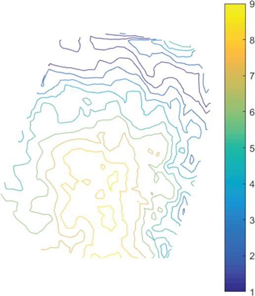
Contour map of displacement magnitude in the direction normal to the cortical surface from Case 8. Contour lines show outward displacements with magnitudes of 1–9 mm. Figure is available in color online only.
For the 5 meningiomas (Cases 3, 7, 8, 15, and 19), tumors in Cases 3, 8, and 15 were partially exposed within the craniotomy, but were not completely contained in the boundaries of the craniotomy, whereas tumors in Cases 7 and 19 were deeper and farther away from the exposed cortical surface.
The accuracy of iSV, measured as RMS error between tracked locations of feature points and their positions on the reconstructed iSV surface, is also reported in Table 2 (seventh column) along with the number of feature points used (in parentheses). The average error in the iSV surface location of these features relative to their stylus positions was 1.20 ± 0.37 mm (range 0.36–1.77 mm). The FRE is reported in the eighth column of Table 2. The FRE is calculated as the RMS error between tracked locations of the fiducial markers and their counterparts identified in the MR images, which differs from the error measure on the navigation system as reported in Table 1.
Computational Efficiency
Computationally intensive tasks were performed on a Linux computer (2.33 GHz, 16 GB RAM) using 12 CPU cores, while other processing such as iSV acquisition and reconstruction occurred on a Windows computer (3.30 GHz, 40 GB RAM). Brain segmentation and meshing were performed prior to craniotomy, typically as soon as pMR images became available. The automatic segmentation was completed within 2 minutes and meshing within 30 sesconds. After dural opening, the iSV image pair of the cortical surface was acquired within 1 second and included both the images and tracking data from Stealth-Link for coregistration with MRI. Reconstruction of the iSV surface was typically performed in less than 1 minute. The total computational time for pMR-iSV registration was 1–2 minutes, depending on the size of the region of interest and displacement magnitude. Whole-brain deformation was computed within 3 minutes, depending on mesh size. Updated MR was produced from the model estimates in less than 15 seconds. Thus, the total computational time to generate uMR for intraoperative use was typically within 7–8 minutes after the iSV images of the exposed cortical surface became available. In Table 2, we report the total computational time of all intraoperative steps (iSV reconstruction, pMR to iSV registration, boundary condition assignment, modeling, and uMR image formation), which was 7.7 minutes on average (range 4–11 minutes).
Discussion
Results from 20 clinical cases show that uMR was more accurate than pMR. Qualitatively, uMR results obtained intraoperatively by navigating to known landmarks and comparing views relative to pMR in the same orientation through simultaneous side-by-side displays on the StealthStation showed uMR was in agreement in all cases, whereas misalignment was evident in pMR in 14 of the 20 cases (in which brain shift > 5 mm was reported as pMR misfit; Table 2). Quantitatively, uMR resulted in TRE and misfits less than 2 mm (TRE = 1.60 ± 0.43 mm, misfit = 1.80 ± 0.35 mm) whereas these values were greater than 5 mm for pMR (TRE = 7.31 ± 2.82 mm, misfit = 7.10 ± 2.78 mm), and uMR accounted for approximately 71% of the observed brain shift, similarly to the percentage of shift corrected as reported by Sun et al.24 (60.7%–87.9% for the 5 cases).
The initial pMR misfit is a combination of brain deformation, FRE (3.06 ± 1.23 mm), and errors in surface registration itself (approximately 2 mm in a previous study,7 and includes inaccuracies in both registration algorithms and the iSV system). In this study, the average accuracy of the iSV system of 1.20 mm was consistent with errors reported previously (approximately 1 mm14). The pMR TRE of 7.31 ± 2.82 mm is on the same order as the initial misfit, and similarly, is a combination of brain deformation, FRE, errors in the iSV system, and feature identification errors. The uMR misfit does not include FRE or other system errors. Similarly, the uMR TRE does not include FRE, and is a combination of the uMR misfit, tracking errors, and feature identification errors. Both of these uMR accuracy assessments were approximately 1–2 mm, comparable to other errors expected in the navigation system and process.
The overall computational efficiency of the image updating process was approximately 7–8 minutes. Because pMR was available prior to surgery, brain segmentation and meshing were performed preoperatively or while the patient was being prepared for surgery, and therefore were not included in the efficiency assessment. Efficiency can be further improved through code optimization and graphics processing unit (GPU) acceleration. For example, by implementing the optical flow stereo-matching algorithm in the GPU, we reduced the iSV reconstruction time from approximately 1–2 minutes to about 5 seconds. Intra-operative data were transferred from the local computer to a remote host, and uMR was retrieved when the modeling process was finished. Data transfer between the local and remote workstations was manual, and required approximately 2 minutes of additional time depending on network speed. In addition, uMR was transferred to the StealthStation for intraoperative validation and comparison, which also increased the workflow time by approximately 1 minute. Thus, the actual time from iSV acquisition to visualization of uMR on the StealthStation was approximately 10 minutes. While the time spent on data transfer can be reduced through automation, or eliminated by performing all tasks on a local computer, the image updating process, including data acquisition, computations, and data transfer, did not alter or influence surgical workflow, as they were executed on a dedicated workstation while the surgeon was operating. In comparison, iMR acquisition interrupts surgery and requires additional time and personnel to reposition the patient and equipment in the OR. Furthermore, because iMR is not inherently coregistered with pMR, additional registration4,8 is required to align the two sets of imaging data if navigation is needed for the remainder of the case. Thus, the resulting total time for iMR acquisition is typically longer than 20 minutes.
Some limitations exist in this study. First, the surface registration technique only applies to cases in which common features such as blood vessels are visible in both iSV and pMR. Lighting can negatively influence iSV image quality due to specular reflections. Under these conditions, displacement data cannot be extracted from the iSV-to-pMR surface registration, and we have developed other methods that incorporate iUS,11,26 which is complementary to iSV for these situations, and also recovers data on brain shift below the surgical surface. Second, we only compensated for brain deformation due to dural opening in this study. As surgery progresses, the cortical surface may deform more significantly from retraction/removal of tissue, and a direct registration between pMR and iSV may not be possible. As an alternative, we have developed techniques to register iSV surfaces between different temporal stages of surgery, where we can track motion over time using optical flow.12 Furthermore, iUS can be combined with iSV for later-stage image updating,6,11 as shift deeper in the brain occurs and iSV alone is not able to capture these displacements. Here, image updating can be repeated multiple times throughout surgery, where uMR from the last update serves as input for the next stage. Effort is currently underway to compensate for later-stage brain deformation by combining iUS with iSV, and validate uMR results by comparing against the gold standard (iMR).
Conclusions
We have developed an image updating system to compensate for brain deformation caused by dural opening by incorporating cortical surface data from iSV. We applied the methods to 20 patients, produced uMRs in the OR, and displayed them side-by-side with pMR on a commercial navigation system within about 10 minutes after dural opening. To validate the results, we visually compared uMR against pMR by navigating to known landmarks, and overlaid iSV with uMR and pMR, respectively, to compare their alignment with respect to both geometry and texture. In addition, we quantified uMR accuracy in terms of the model-data misfit and compared uMR with pMR through TREs at feature points that were visible on the cortical surface and in the MR image volume. Our results show that these measurements of error were approximately 1–2 mm (misfit 1.80 ± 0.35 mm, TRE 1.60 ± 0.43 mm) for uMR versus approximately 7 mm on average (misfit 7.10 ± 0.78 mm, TRE 7.31 ± 2.82 mm) for pMR. The computational costs required to generate uMR intraoperatively were approximately 7–8 minutes and included the steps of image acquisition and reconstruction, surface registration, model computations, and image updating. These results indicate that compensation of brain shift from dural opening using a computational model to generate uMR views can be accomplished in the OR, and more importantly, they demonstrate that improved coregistration accuracy is obtained relative to continuing with pMR.
Acknowledgments
This research was supported by NIH grant no. R01 CA159324-03. We acknowledge the support of Medtronic Navigation for use of the StealthStation S7 and Carl Zeiss (Carl Zeiss Surgical GmbH) for use of the OPMI Pentero operating microscope.
ABBREVIATIONS
- FRE
fiducial registration error
- GPU
graphics processing unit
- iMR
intraoperative magnetic resonance imaging scanner
- iSV
intraoperative stereovision
- iUS
intraoperative ultrasound
- OR
operating room
- pMR
preoperative magnetic resonance images
- RMS
root mean square
- TRE
target registration error
- uMR
updated magnetic resonance images.
Footnotes
Disclosures
The authors report no conflict of interest concerning the materials or methods used in this study or the findings specified in this paper.
Author Contributions
Conception and design: Paulsen, Fan, Roberts, Simon. Acquisition of data: Fan, Roberts. Analysis and interpretation of data: Paulsen, Fan, Roberts. Drafting the article: Fan. Critically revising the article: Paulsen, Roberts. Reviewed submitted version of manuscript: all authors. Approved the final version of the manuscript on behalf of all authors: Paulsen. Administrative/technical/material support: Schaewe. Study supervision: Paulsen, Roberts.
References
- 1.Ammirati M, Gross JD, Ammirati G, Dugan S. Comparison of registration accuracy of skin- and bone-implanted fiducials for frameless stereotaxis of the brain: a prospective study. Skull Base. 2002;12:125–130. doi: 10.1055/s-2002-33458-1. [DOI] [PMC free article] [PubMed] [Google Scholar]
- 2.Buckner JC. Factors influencing survival in high-grade gliomas. Semin Oncol. 2003;30(6 Suppl 19):10–14. doi: 10.1053/j.seminoncol.2003.11.031. [DOI] [PubMed] [Google Scholar]
- 3.Carter TJ, Sermesant M, Cash DM, Barratt DC, Tanner C, Hawkes DJ. Application of soft tissue modelling to image-guided surgery. Med Eng Phys. 2005;27:893–909. doi: 10.1016/j.medengphy.2005.10.005. [DOI] [PubMed] [Google Scholar]
- 4.Clatz O, Delingette H, Talos IF, Golby AJ, Kikinis R, Jolesz FA, et al. Robust nonrigid registration to capture brain shift from intraoperative MRI. IEEE Trans Med Imaging. 2005;24:1417–1427. doi: 10.1109/TMI.2005.856734. [DOI] [PMC free article] [PubMed] [Google Scholar]
- 5.Ding S, Miga MI, Thompson RC, Dumpuri P, Cao A, Dawant BM. Estimation of intra-operative brain shift using a tracked laser range scanner. Conf Proc IEEE Eng Med Biol Soc. 2007;2007:848–851. doi: 10.1109/IEMBS.2007.4352423. [DOI] [PubMed] [Google Scholar]
- 6.Fan X, Ji S, Fontaine K, Hartov A, Roberts D, Paulsen K. Simulation of brain tumor resection in image-guided neurosurgery. Proc SPIE. 2011;7964:79640U. [Google Scholar]
- 7.Fan X, Ji S, Hartov A, Roberts DW, Paulsen KD. Stereovision to MR image registration for cortical surface displacement mapping to enhance image-guided neurosurgery. Med Phys. 2014;41:102302. doi: 10.1118/1.4894705. [DOI] [PMC free article] [PubMed] [Google Scholar]
- 8.Ferrant M, Nabavi A, Macq B, Jolesz FA, Kikinis R, Warfield SK. Registration of 3-D intraoperative MR images of the brain using a finite-element biomechanical model. IEEE Trans Med Imaging. 2001;20:1384–1397. doi: 10.1109/42.974933. [DOI] [PubMed] [Google Scholar]
- 9.Garlapati RR, Roy A, Joldes GR, Wittek A, Mostayed A, Doyle B, et al. More accurate neuronavigation data provided by biomechanical modeling instead of rigid registration. J Neurosurg. 2014;120:1477–1483. doi: 10.3171/2013.12.JNS131165. [DOI] [PMC free article] [PubMed] [Google Scholar]
- 10.Helm PA, Eckel TS. Accuracy of registration methods in frameless stereotaxis. Comput Aided Surg. 1998;3:51–56. doi: 10.1002/(SICI)1097-0150(1998)3:2<51::AID-IGS1>3.0.CO;2-J. [DOI] [PubMed] [Google Scholar]
- 11.Ji S, Fan X, Hartov A, Roberts D, Paulsen K. Estimation of intraoperative brain deformation. In: Payan Y, editor. Soft Tissue Biomechanical Modeling for Computer Assisted Surgery. Vol. 11. Berlin: Springer; 2012. pp. 97–133. [Google Scholar]
- 12.Ji S, Fan X, Roberts DW, Hartov A, Paulsen KD. Cortical surface shift estimation using stereovision and optical flow motion tracking via projection image registration. Med Image Anal. 2014;18:1169–1183. doi: 10.1016/j.media.2014.07.001. [DOI] [PMC free article] [PubMed] [Google Scholar]
- 13.Ji S, Fan X, Roberts DW, Hartov A, Paulsen KD. Flow-based correspondence matching in stereovision. In: Wu G, Zhang D, Shen D, et al., editors. Machine Learning in Medical Imaging: 4th International Workshop, MLMI 2013, Held in Conjunction with MICCAI 2013, Nagoya, Japan, September 22, 2013. Proceedings. Cham, Switzerland: Springer; 2013. pp. 106–113. [Google Scholar]
- 14.Ji S, Fan X, Roberts DW, Paulsen KD. Efficient stereo image geometrical reconstruction at arbitrary camera settings from a single calibration. Med Image Comput Comput Assist Interv. 2014;17:440–447. doi: 10.1007/978-3-319-10404-1_55. [DOI] [PMC free article] [PubMed] [Google Scholar]
- 15.Ji S, Roberts DW, Hartov A, Paulsen KD. Brain-skull contact boundary conditions in an inverse computational deformation model. Med Image Anal. 2009;13:659–672. doi: 10.1016/j.media.2009.05.007. [DOI] [PMC free article] [PubMed] [Google Scholar]
- 16.Joldes GR, Wittek A, Couton M, Warfield SK, Miller K. Real-time prediction of brain shift using nonlinear finite element algorithms. Med Image Comput Comput Assist Interv. 2009;12:300–307. doi: 10.1007/978-3-642-04271-3_37. [DOI] [PubMed] [Google Scholar]
- 17.Lacroix M, Abi-Said D, Fourney DR, Gokaslan ZL, Shi W, DeMonte F, et al. A multivariate analysis of 416 patients with glioblastoma multiforme: prognosis, extent of resection, and survival. J Neurosurg. 2001;95:190–198. doi: 10.3171/jns.2001.95.2.0190. [DOI] [PubMed] [Google Scholar]
- 18.Lunn KE, Paulsen KD, Lynch DR, Roberts DW, Kennedy FE, Hartov A. Assimilating intraoperative data with brain shift modeling using the adjoint equations. Med Image Anal. 2005;9:281–293. doi: 10.1016/j.media.2004.12.003. [DOI] [PubMed] [Google Scholar]
- 19.Nimsky C, Ganslandt O, Hastreiter P, Fahlbusch R. Intraoperative compensation for brain shift. Surg Neurol. 2001;56:357–365. doi: 10.1016/s0090-3019(01)00628-0. [DOI] [PubMed] [Google Scholar]
- 20.Paulsen KD, Miga MI, Kennedy FE, Hoopes PJ, Hartov A, Roberts DW. A computational model for tracking subsurface tissue deformation during stereotactic neurosurgery. IEEE Trans Biomed Eng. 1999;46:213–225. doi: 10.1109/10.740884. [DOI] [PubMed] [Google Scholar]
- 21.Roberts DW, Miga MI, Hartov A, Eisner S, Lemery JM, Kennedy FE, et al. Intraoperatively updated neuroimaging using brain modeling and sparse data. Neurosurgery. 1999;45:1199–1207. [PubMed] [Google Scholar]
- 22.Stummer W, Reulen HJ, Meinel T, Pichlmeier U, Schumacher W, Tonn JC, et al. Extent of resection and survival in glioblastoma multiforme: identification of and adjustment for bias. Neurosurgery. 2008;62:564–576. doi: 10.1227/01.neu.0000317304.31579.17. [DOI] [PubMed] [Google Scholar]
- 23.Sun H, Lunn KE, Farid H, Wu Z, Roberts DW, Hartov A, et al. Stereopsis-guided brain shift compensation. IEEE Trans Med Imaging. 2005;24:1039–1052. doi: 10.1109/TMI.2005.852075. [DOI] [PubMed] [Google Scholar]
- 24.Sun K, Pheiffer TS, Simpson AL, Weis JA, Thompson RC, Miga MI. Near real-time computer assisted surgery for brain shift correction using biomechanical models. IEEE J Transl Eng Health Med. 2(2):2014. doi: 10.1109/JTEHM.2014.2327628. [DOI] [PMC free article] [PubMed] [Google Scholar]
- 25.Tsai RY. A versatile camera calibration technique for high-accuracy 3D machine vision metrology using off-the-shelf TV cameras and lenses. IEEE J Robot Autom. 1987;3:323–344. [Google Scholar]
- 26.Valdés PA, Fan X, Ji S, Harris BT, Paulsen KD, Roberts DW. Estimation of brain deformation for volumetric image updating in protoporphyrin IX fluorescence-guided resection. Stereotact Funct Neurosurg. 2010;88:1–10. doi: 10.1159/000258143. [DOI] [PMC free article] [PubMed] [Google Scholar]
- 27.Wu Z, Paulsen KD, Sullivan JM., Jr Adaptive model initialization and deformation for automatic segmentation of T1-weighted brain MRI data. IEEE Trans Biomed Eng. 2005;52:1128–1131. doi: 10.1109/TBME.2005.846709. [DOI] [PubMed] [Google Scholar]
- 28.Zhuang DX, Liu YX, Wu JS, Yao CJ, Mao Y, Zhang CX, et al. A sparse intraoperative data-driven biomechanical model to compensate for brain shift during neuronavigation. AJNR Am J Neuroradiol. 2011;32:395–402. doi: 10.3174/ajnr.A2288. [DOI] [PMC free article] [PubMed] [Google Scholar]