

Abstract

Additive manufacturing (AM) alias 3D printing translates computer-aided design (CAD) virtual 3D models into physical objects. By digital slicing of CAD, 3D scan, or tomography data, AM builds objects layer by layer without the need for molds or machining. AM enables decentralized fabrication of customized objects on demand by exploiting digital information storage and retrieval via the Internet. The ongoing transition from rapid prototyping to rapid manufacturing prompts new challenges for mechanical engineers and materials scientists alike. Because polymers are by far the most utilized class of materials for AM, this Review focuses on polymer processing and the development of polymers and advanced polymer systems specifically for AM. AM techniques covered include vat photopolymerization (stereolithography), powder bed fusion (SLS), material and binder jetting (inkjet and aerosol 3D printing), sheet lamination (LOM), extrusion (FDM, 3D dispensing, 3D fiber deposition, and 3D plotting), and 3D bioprinting. The range of polymers used in AM encompasses thermoplastics, thermosets, elastomers, hydrogels, functional polymers, polymer blends, composites, and biological systems. Aspects of polymer design, additives, and processing parameters as they relate to enhancing build speed and improving accuracy, functionality, surface finish, stability, mechanical properties, and porosity are addressed. Selected applications demonstrate how polymer-based AM is being exploited in lightweight engineering, architecture, food processing, optics, energy technology, dentistry, drug delivery, and personalized medicine. Unparalleled by metals and ceramics, polymer-based AM plays a key role in the emerging AM of advanced multifunctional and multimaterial systems including living biological systems as well as life-like synthetic systems.
1. Introduction
First introduced during the 1980s to serve the highly specialized needs of model making and rapid prototyping (RP), additive manufacturing (AM) alias 3D printing has emerged as a versatile technology platform for computer-assisted design (CAD) and rapid manufacturing. AM allows the production of customized parts from metals, ceramics, and polymers without the need for molds or machining typical for conventional formative and subtractive fabrication. Today 3D printers are commercially available for less than $500, enabling desktop fabrication of 3D objects even at home. In the same way that the development of digital 2D printing together with desktop publishing has revolutionized communication and information technology, the development of AM technologies in conjunction with the “internet of things” has the potential to revolutionize computer-guided fabrication of both complex objects and multifunctional materials systems. Whereas conventional fabrication is governed by processing constraints related to industrial mass production, AM is inherently agile enabling faster turnaround on design and manufacturing of customized objects tailored to meet the demands of individuals and specific applications. In literature, the terms additive manufacturing, rapid prototyping, layered manufacturing, solid freeform fabrication, 3D fabbing, and 3D printing are used more or less synonymously. While “additive manufacturing” is preferred by most engineers, the term “3D printing” is far more common particularly in the popular media. In this work, the terms “additive manufacturing” (AM) and 3D printing are both used to describe the same general manufacturing principle.
AM allows the production of 3D structures with high shape complexity. Although a coffee mug is not very complex, it provides a convenient object to demonstrate the concepts of AM (Figure 1). In the first step, CAD is used to create a virtual object, which is then digitally sliced. Objects with overhanging portions (i.e., the coffee mug handle) are designed with temporary support structures to prevent collapse during the build process. The coordinates of the virtual object and digital slices are then used to steer the motors, which control the position of the building device or the 3D-dispenser orifice, respectively. For practical purposes, this type of computer-aided manufacturing (CAM) is normally performed layer by layer with typical layer thicknesses ranging from 15 to 500 μm. When the layer thickness is below 50 μm, the naked eye will in most cases not be able to recognize the stair-steps associated with a layered manufacturing approach. For thicker layers or in demanding applications, postprocessing may be used to remove support structures or to improve surface properties. As compared to conventional polymer processing (see Figure 2) by formative techniques like injection molding and subtractive techniques like CNC machining, AM is slower but enables CAD-guided fabrication of multifunctional material systems with complex shapes and functionalities, including bio systems.
Figure 1.
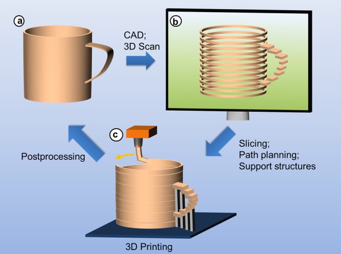
Basic principles of additive manufacturing. (a) Development of product idea that is transformed into digital data by means of CAD, or analysis of geometric data by means of 3D scanning; (b) preprocessing of model data: slicing of virtual model into layered data, adjustment of support structures to stabilize craning structures, path planning, and successive transfer of layered data to 3D printer; (c) and additive manufacturing of model or product, for example, by melt extrusion, postprocessing to remove typical artifacts including support structures and surface roughness due to staircase effects.
Figure 2.

Comparison of (a) subtractive, (b) additive, and (c) formative manufacturing techniques.
With the development of easy-to-use systems exhibiting sufficiently fast build-speeds and decreased system prices, AM has moved from the arena of niche-manufacturing processes into the spotlight of a much larger audience. Despite the significant progress that has been achieved in recent years, there are still a number of challenges that need to be tackled to establish AM as a manufacturing tool on a large scale. Many of these challenges are related to the insufficient material properties (thermomechanical properties, anisotropy, porosity, long-term stability, cost, corrosion properties, creep, etc.) of the currently used build materials. With a focus on polymeric materials, this Review describes the different AM processes that use polymers along with the technical requirements of the utilized materials. Critical points, which currently limit the further use of AM in manufacturing, will be pointed out, and possible strategies for overcoming these issues will be discussed.
The increasingly large number of AM processes can be categorized employing different criteria, ranging from the application (visual prototyping, functional prototyping, rapid tooling, and rapid manufacturing) to the initial condition of processed materials or the physical principle underlying the mostly layerwise solidification process.1 In 2009 the ASTM International Committee F42 on Additive Manufacturing Technology defined a number of terms to distinguish additive manufacturing technologies from their formative and subtractive competitors (Figure 2) and to classify different additive manufacturing processes.2,3 We aim to follow this nomenclature in the course of this Review:
Material extrusion is an additive manufacturing process in which material is selectively dispensed through a nozzle. Fused deposition modeling (FDM), fused filament fabrication (FFF), 3D dispensing, and 3D bioplotting fall into this category.
Material jetting is an additive manufacturing process in which droplets of build material (such as photopolymer or thermoplastic materials) are selectively deposited. Systems based on inkjet-printing fall into this category.
Binder jetting is an additive manufacturing process in which a liquid bonding agent is selectively deposited to fuse powder materials.
Sheet lamination is an additive manufacturing process in which sheets of material are bonded together to form an object.
Vat photopolymerization is an additive manufacturing process in which liquid photopolymer in a vat is selectively cured by light-activated polymerization. Many of the lithography-based AM approaches (e.g., multiphoton polymerization (2PP), digital light processing (DLP), and stereolithography (SLA)) can be grouped into this category.
Powder bed fusion is an additive manufacturing process in which thermal energy (provided, e.g., by a laser or an electron beam) selectively fuses regions of a powder bed. Selective laser sintering (from 3D Systems) and laser sintering (from EOS), both of which are abbreviated in this Review as SLS, and electron beam machining (EBM) fall into this category. These processes are used for metals as well as polymers.
Directed energy deposition is an additive manufacturing process in which focused thermal energy (e.g., laser or plasma arc) is used to fuse materials by melting as they are being deposited. This process is currently only used for metals.
Table 1 lists the AM techniques covered in this Review with some of their more pertinent features and limitations. The typical and largest build volumes for commercially available instruments are also listed and named in parentheses.
Table 1. Categorized AM Techniques for Polymers along with Advantages and Disadvantages.
| categorized techniques | typical and largest build volume | typical feature resolution | typical materials | advantages | disadvantages |
|---|---|---|---|---|---|
| Vat Photopolymerization | |||||
| exposure from top | 250 × 250 × 250 mm3 | 50–100 μm | acrylates/epoxides | excellent surface quality and precision | limited mechanical properties |
| 800 × 330 × 400 mm3 (Prodways) | |||||
| CLIP | 150 × 80 × 300 mm3 | 75 μm | acrylates | high build speed | low-viscosity resins required |
| exposure from bottom | 100 × 100 × 100 mm3 | 25–100 μm | acrylates/epoxides | low initial vat volume; better surface quality | limited mechanical properties |
| 300 × 300 × 300 mm3 (DigitalWax 30X) | |||||
| multiphoton lithography | 5 × 5 × 1 mm3 | 0.1–5 μm | acrylates | very high resolution | low build speed; limited materials |
| 100 × 100 × 3 mm3 (Nanoscribe) | |||||
| Powder Bed Fusion | |||||
| polymer SLS | 250 × 250 × 250 mm3 | 50–100 μm | PA12, PEEK | best mechanical properties; less anisotropy | rough surfaces; poor reusability of unsintered powder |
| 1400 × 1400 × 500 mm3 (Huake 3D HKS1400) | |||||
| Material and Binder Jetting | |||||
| polyjet | 300 × 200 × 150 mm3 | 25 μm | acrylates | fast; allows multimaterial AM | low viscosity ink required |
| 1000 × 800 × 500 mm3 (Objet 1000) | |||||
| aerosol jet printing | 200 × 300 × 200 mm3 (Aerosol Jet 5X) | 10 μm | conductive inks/dielectrics | high resolution; low temp process | low viscosity ink required |
| 3D printing (binder jetting) | 200 × 250 × 200 mm3 | 100 μm | starch, PLA, ceramics | fast; allows multimaterial AM; low temp | limited strength of parts; rough surfaces |
| 1000 × 600 × 500 mm3 (Voxeljet) | |||||
| Sheet Lamination | |||||
| laminated object manufacturing | 170 × 220 × 145 mm3 (Solidimension SD300) | 200–300 μm | PVC, paper | compact desktop 3D printer | limited materials; low resolution; high anisotropy |
| Material Extrusion | |||||
| FDM | 200 × 200 × 200 mm3 | 100–150 μm | ABS, PLA, PC, HIPS | inexpensive machines and materials | rough surfaces; high temperature process |
| 1005 × 1005 × 1005 mm3 (BigRep One) | |||||
| 3D dispensing | 150 × 150 × 140 mm3 (3D Bioplotter) | 100 μm to 1 cm | thermo-plastics, composites, photoresins, hydrogels, biomaterials | broad range of materials | rough surfaces; narrow viscosity process window |
1.1. Scientific and Technological Impact
The scientific and technological impact of AM has steadily increased since the first commercial instruments were introduced in the late 1980s. Figure 3 represents this trend graphically by tracing the yearly number of scientific publications and patents from 1985 to 2016 using the terms “additive manufacturing” and “rapid prototyping” (Figure 3). As testimony to these developments, references for books and review articles from this time period on AM and RP are provided here.1,4−9 Whereas interest in “additive manufacturing” has grown steadily for the last 25 years, the comparatively younger field of bioprinting (which is based on AM) has witnessed a comparatively impressive increase in patents and publications within the past decade. This growth (expressed in units on the right-hand side of Figure 3 for better comparison) is expected to continue and may in the near future reach the levels of AM and RP.
Figure 3.

Research interest in rapid prototyping, 3D printing, additive manufacturing and bioprinting, as indicated by the number of hits per annum for the respective terms (data from Web of Science, accessed July 27, 2017).
1.2. Economic Impact
The initial economic motivation for the development of AM in the 1980s (better known as RP at that time) was to accelerate and lower the costs related to product development. In comparison to subtractive manufacturing technologies such as computerized numerical control (CNC) machining, AM is less wasteful (in terms of both construction material and replacement machine tools) and enables the incorporation of more complex internal substructures and undercuts. By providing designers with novel processes enabling them to efficiently create and amend physical models for validation purposes, design mistakes could be identified earlier. Resulting amendments were shifted to earlier stages of product development, enabling design security and eliminating the need for expensive corrections at later stages.6,10,11
AM finds application in manufacturing of custom-made parts, including prototypes, and small series parts. AM is not only by far more flexible than conventional formative molding or casting processes, but may as well be considered economically favorable in cases where the high financial and time expenditure necessary for the production of molds and tools for formative manufacturing exceeds the usually higher production costs per part in AM.
In recent years, the overall market situation for AM was characterized by significant growth rates, as indicated by Figure 4. Revenues from services as well as products (systems and materials) have grown since the 2008 crisis, and worldwide numbers surpassed the value of 5 billion USD in 2015.7 This significant growth spurred a lot of interest in AM-related activities, and major players in the manufacturing industry (aerospace, energy, automotive, consumer products, and medical/dental) have started activities in the field.
Figure 4.

Worldwide revenues from AM products and services between 1995 and 2016. Data from ref (12).
AM is currently able to fabricate parts made of metals, polymers, and ceramics. As indicated in Figure 5, the revenues from material sales passed the value of 900 million USD in 2016. Interestingly, the largest fraction of these material sales still goes into photopolymers (350 million USD), despite the fact that, with a few exceptions, photopolymers are currently mostly used for molding and prototyping applications. AM metals worth 127 million USD were sold in 2016, and an estimated amount of 225 million USD was spent on polymer powders for laser sintering.13 The remaining revenues mostly come from sales of polymer filaments for fused deposition modeling (FDM). Polymers are therefore clearly the most widely used material class for AM.
Figure 5.

Worldwide revenues from AM material sales between 2000 and 2016. Data from ref (12).
As AM became more established, and the quality of processes and materials reached a higher level, applications have widened to include prototypes for functional testing (functional prototyping). In parallel, the increasingly competitive accuracy of CAD reproduction and surface quality has enabled the use of AM in the tooling sector (rapid tooling), either by directly producing molds or by combining additive manufacturing with postprocessing techniques like CNC-machining or electro-discharge machining.1,6,14,15
The economic feasibility of additive manufacturing for end-user parts is mainly dependent on the number and bulk speed of identical parts that are to be produced. While impractical for mass production of simple objects, AM can outrun conventional, especially formative, manufacturing techniques in applications with a high level of individuality. There are some clinical applications that serve as examples where direct fabrication for the consumer is well-established. In osteoplastics, prosthetic dentistry, and orthodontics, precisely fitting implants or supports are often manufactured by AM. In these cases, end-user parts can be produced directly according to tomographic patient data.16−23 Further fields with commercial relevance include architecture, urban development, and jewelry.24,25
1.3. Challenges in Process and Materials Development for 3D Printing and Customized Additive Manufacturing
With the increasingly widespread use of AM in ever more challenging applications, increased demands are placed on the parameters of the build process and on the performance of the finished object.26 Generally the shortcomings of AM can be looked at as areas of opportunity, and indeed it is in response to these problems where the majority of new developments in the field have arisen. Listed are the more serious of these shortcomings.
1.3.1. Build Speed
The term rapid prototyping, which is commonly used synonymously with AM, can be somewhat misleading with regards to the build speed. Although AM processes facilitate a much faster product development by reducing the time necessary for design validations and enabling the production of functional prototypes already at early stages in development, AM is still slow in comparison to mass production technologies such as injection molding. Up to now, this has been acceptable in a multitude of applications such as customized manufacturing that take advantage of the flexibility of AM processes. Nevertheless, the struggle to broaden the scope of application in the future has been a key motivator for research activities, for example, ranging from advanced path planning procedures for SLA in the 1990s to the development of continuous liquid interface production (CLIP) in 2015 by DeSimone et al.4,27 Videos of the CLIP process are available online displaying both its speed and its continuous nature, which is likened to the shapeshifting robot from the movie Terminator 2.28,29
1.3.2. Mechanical Properties
As application of AM progresses from (visual) prototyping to manufacturing of end-user parts, the functionality of these parts is expected to match or surpass the performance of products fabricated using subtractive and formative technologies. Despite numerous research activities, products produced by AM are inferior with respect to mechanical properties in many cases. Depending on the specific process employed, this weakness may be due to a limited choice of materials suited for a process (e.g., photocurable vinyl- or epoxy-functional oligomers for photopolymerization in the case of SLA)30 or to an unavoidable porosity of parts derived from powder bed fusion or material extrusion.31,32 Moreover, due to the layered production process, mechanical properties of parts tend to be anisotropic, with the boundary between adjacent layers representing weak regions with maximum residual stresses in applications where mechanical integrity is a major concern.33 Kotlinski conducted an in-depth analysis of the mechanical properties of commercial AM materials and techniques and found anisotropy to be the worst for LOM and least critical with SLS.34 Mechanical properties and anisotropy for FDM were found to be highly dependent on material and process parameters.35 Anisotropy is also a problem with lithographic AM, where postcuring has been found to provide improvements.36 Improving the mechanical properties of AM formed objects is an active area of research, where the development and application of composite materials can provide unique solutions.37
1.3.3. Resolution
Another major concern influenced both by the specific AM technique and by the processed material is spatial resolution. Insufficient resolution can have a dramatic influence on the quality and functionality of an object. While the formed object is expected to have high fidelity with the CAD virtual object, limitations of the technique and of the build material mean that some degree of dimensional inaccuracies is to be expected. Most prominently, stair step surfaces (Figure 1) are an inherent feature of layer by layer manufacturing, which may require postprocessing (coating, solvent treatment, sanding, or milling).
Resolution requirements set by advanced applications of AM have triggered a lot of research in the fields of engineering and materials science. Using vat photopolymerization as an example, material parameters governing resolution include the absorption and curing characteristics of the respective material. Both are strongly dependent on the monomers used along with the presence of initiator and inhibitor. Where the initiator induces photo-cross-linking and thus solidification within irradiated regions, the inhibitor causes termination on the borderline to dark regions.5 Process parameters influencing the x–y resolution of vat-photopolymerization techniques include the minimum resolution of the light source employed and path planning operations for processes based on laser-scanning. Resolution in the z-direction as described by the minimum layer thickness is dependent on the accuracy of the step motor operating the build platform and on the efficiency of the recoating process (which is dependent on viscosity of the photoresin). It was only very recently that 3D carbon’s novel continuous liquid interface production (CLIP) overcame this drawback by eliminating the need for stepwise processing.27
Similar considerations have to be made for other AM processes, for example, the minimum strand thicknesses tolerable in material extrusion processes, which depend on the rheological properties of the processed materials, or the minimum size of powder particles in powder bed fusion and powder binding-based manufacturing processes, the latter being determined by safety considerations and the limits set by powder production processes.
1.3.4. Multimaterial Parts
AM is prevalently used for prototypes and models, where the option to print in multiple colors is interesting for aesthetic and for demonstration purposes. Commercial multicolor 3D printers have become increasingly common, with entry-level FDM printers starting below $1000.38 These printers use different color filaments from the same material (typically PLA or ABS). By comparison, processing two or more different materials within a single print job is more complicated due to differences in reactivity, in thermal and rheological behavior, and due to incompatibilities either from the materials themselves or from the different techniques used to process them.39 Almost all AM techniques have been modified in some form to allow multimaterial AM (MMAM), but only a few of these modified techniques have actually been commercialized. MMAM is possible by vat photopolymerization by using multiple vats and transferring the object between vats during building.40,41 Powder bed MMAM has also been demonstrated, where one powder material is exchanged for another during building.42 These MMAM techniques are limited though due to contamination issues, slow transfer from one material to another, and more fundamentally by the fact that material exchange is possible only between layers (1D multimaterial) and not within layers (3D multimaterial). Material jetting MMAM based on drop on demand (DOD) technology, by comparison, allows rapid exchange between build materials at each 1D point within a 3D print job.43 This technique is also limited due to the narrow process window of the ink jet actuator. Hope is offered by multi actuator jetting systems, which allow printing of materials with different viscosities and electrical properties. To build free-standing objects from two fundamentally different materials (i.e., metals and polymers), multiprocess 3D printing uses a robot to transfer the object between two or more different AM machines during fabrication.44 MMAM plays an important role in AM for bioprinting and applications in medicine and life sciences.
1.3.5. Biocompatibility and Other Concerns for Medical Applications
One of the most promising applications for AM is in the field of personalized medicine, where tomographic images (from X-ray, MRI, etc.) can be used to print objects contoured specifically for the patient. AM is used in surgical planning, in building prosthetics, in dentistry, and in tissue engineering.45−51 Using AM to build tissue grafts and other surgical implants is an intense area of research, where special consideration for both the build material and the AM technique must be considered. For example, acrylates, which are used in all lithographic AM methods (SLA, Polyjet), are cytotoxic but can be replaced by less reactive methacrylates, thiol–ene systems, and other photoreactive monomers.52,53 PLA, which is one of the most commonly used materials for FDM, is also FDA approved for human implantation but has poor mechanical properties.54 Moreover, FDM is a melt extrusion process and does not allow incorporation of living cells or growth factors. Bioplotting is a versatile room-temperature AM method, which can process hydrogels with cells and growth factors.55,56 Control of temperature and of other process parameters, particularly for multimaterial bioplotting, is not straightforward, and research groups are investigating different approaches to alleviate these issues.
2. Vat Photopolymerization
2.1. Techniques
2.1.1. Stereolithography
In the early 1980s, Kodama described methods for building solids by selectively exposing photopolymers either with masks or with optical fibers manipulated by an X–Y plotter.58,59 At about the same time, Herbert presented similar methods using a plotter to direct a laser beam and a lab jack to control the z-direction.60 In 1984, two independent patents (one in France by André et al. and the other in the United States by Chuck Hull) were filed describing layer by layer lithographic fabrication of solids.61 While the French patent was abandoned for business reasons, Hull’s patent both coined the term “stereolithography” (SLA) and laid the groundwork for this technique and for commercial additive manufacturing.57
Figure 6 illustrates the principal components of an SLA device and how they fit together to allow layer by layer fabrication. In the late 1980s, SLA instruments became commercially available first in the U.S. by Hull’s 3D Systems and not long after in Japan by CMET.62 In SLA systems, coherent light sources (usually lasers emitting in the UV-range) are used to induce polymerization and cross-linking of the initially liquid resin. One of the main advantages of SLA is the high spatial resolution provided by the spot size of the focused laser beam. With SLA, light exposure is performed sequentially by scanning the laser beam within the plane on the surface of the photosensitive material. The time necessary to produce one slice of the structure therefore depends on the speed with which the laser beam is scanned and on the illuminated area. The lateral position of the laser beam is usually controlled by a pair of mirrors within a galvanoscanner. As with most other AM technologies, the process is executed in a layer by layer manner. The slice information is presented in the form of a set of coordinates, defining the tilt angle of the two mirrors, which guide the position of the laser beam along the plane. The fact that every pixel of the layer is irradiated sequentially would theoretically allow adjustment of exposure dose for every pixel separately, by controlling the laser intensity. This enables SLA to process grayscale patterns. Vertical resolution is dependent on the light penetration depth, which can be controlled by addition of suitable absorbers to the photopolymer resin. The curing depth also depends on the exposure dose (light intensity and illumination time), which might be the main reason why the grayscale capability of SLA is not utilized in practice. It is worth noting that the main time-consuming step in SLA is not the laser-scanning itself, but the deposition of the new layer of photosensitive material. Here, the viscosity of the material plays an important role. Very often nonreactive additives or solvent must be used to decrease the viscosity of the photopolymer resin.
Figure 6.

Image from U.S. Patent 4575330 introducing the term and the concept of stereolithography.57 Description of components using the numbering scheme from the patent: (21) container, (22) UV curable liquid, (23) working surface, (26) UV light source, (27) UV light spot, (28) computer, (29) movable elevator platform, (30) three-dimensional object, and (30a–c) integrated laminae of the object.
An extension of traditional SLA is provided by microstereolithography, which is impractically slow for large objects but offers lateral resolution usually in the range of a few micrometers.63
2.1.2. Digital Light Processing
Digital light processing (DLP) is similar to SLA in that both techniques utilize light to selectively cross-link a photoresin in a layer by layer fashion to build a free-standing object. Different from SLA, each layer is exposed not point-by-point but rather all-at-once with a selectively masked light source (Figure 7).64
Figure 7.

Digital light processing (DLP) consisting of (a) vat filled with photopolymer resin, (b) light source, (c) micromirror array, (d) vertically movable building platform, and (e) tilting device to replenish the uncured bottom layer.21
DLP closely resembles classical lithography, and is often referred to as dynamic mask photolithography. The information for each layer of the structure is provided in the form of black and white images. Such binary patterns are presented via a digital micromirror device (DMD), a technology also used in overhead projectors.65,66 Because the whole layer (slice) of the structure is produced in one exposure step, the build time is considerably shorter than SLA. By the same virtue, the build time is the same whether the whole available illumination field or only a part of it has been exposed. Therefore, DLP processing speed is most often expressed in cm h–1, that is, the height of the structure (number of layers) per unit time. Furthermore, DLP is less affected by oxygen inhibition as compared to SLA, because the layer of resin being polymerized is always on the bottom of the vat and not in direct contact with air. The utilized light sources have rapidly evolved from classical lamps to modern light-emitting diodes (LED) covering a wavelength range from deep UV to visible. The lateral resolution of DLP systems is usually in the range of 10–50 μm depending on the number of pixels/mirrors provided by the DMD and the optics used to project the patterns onto the build platform. The vertical resolution, that is, the smallest possible layer thickness, mainly depends on the light penetration depth into the material and the resulting curing depth. Vertical resolution can be adjusted with light absorbing additives, such as naphthol-based dyes, which in addition help to reduce the unwanted effects associated with scattered light. In addition to nonfilled photopolymers, slurries containing, for example, ceramic or metal particles can be processed with DLP.67 In this case, the photosensitive polymer matrix acts as a binder material, while the fillers are usually photochemically passive. Further discussion of ceramics is provided in the materials section.
2.1.3. Continuous Liquid Interface Production (CLIP)
Continuous liquid interface production (CLIP) is a variety of vat photopolymerization AM pioneered by DeSimone et al., which uses an oxygen permeable film to inhibit polymerization at the surface close to the UV source and as a result remove the need for an intermediate recoating step for each layer.27,68 CLIP is schematically described in Figure 8 and can also be witnessed in videos online, which better capture the dynamics of the process.28 CLIP has several advantages to other forms of SLA and has been commercialized by the company Carbon 3D, Inc., which sells instruments, materials, and services.69
Figure 8.

Continuous liquid interface production (CLIP). Reprinted with permission from ref (27). Copyright 2015 the American Association for the Advancement of Science.
Because the resin recoating step is the most time-consuming operation of the DLP lithography process, CLIP is considerably faster than traditional DLP, allowing production of objects with features below 100 μm at z-axis growth rates of 30 cm h–1. Lower resolution objects can be grown at rates beyond 100 cm h–1. A CLIP device is similar to a DLP device without a tiltable stage and instead with a UV and oxygen permeable window at the bottom of the vat. Oxygen concentration at the bottom of the vat is thus sufficiently high to create a “dead zone” where radical polymerization does not occur. The thickness of this “dead zone” is defined by the following equation, where ϕ0 is photon flux, αPI is the absorption coefficient of the photoinitiator, and Dc0 is the resin curing dosage:
| 1 |
C is a proportionality constant for the oxygen permeable window (30 for a 100 μm thick Teflon AF film with air on the underside). A dead zone thickness of 20–30 μm was generally optimal for fast and precise CLIP. Just above the dead zone, cross-linking occurs in areas illuminated by the imaging unit. Feature resolution in the z direction is improved by increasing the concentration of a passive light absorber. Lowering the concentration of absorber allows deeper light penetration and thus faster production. Although CLIP is fairly new, Carbon 3D has been quick to develop commercial instruments and improved resins allowing the production of objects from hard to elastic polymers as well as ceramics.70,71
2.1.4. Multiphoton Polymerization
The simultaneous absorption of two photons (TPA) was first described theoretically by Maria Göppert-Mayer in 1931,72 and for this her name is given to the unit for quantifying TPA cross section (1 GM = 1 × 10–50 cm4 s molecules–1 photon–1). Although experimental validation of TPA first came in the 1960s,73 it was not until the 1980s that solid-state femtosecond pulsed lasers became available to provide sufficient light intensities to allow TPA in the laboratory. For TPA to occur, photons must be present in sufficiently high concentration to drive a transition via a very short-lived (fs) intermediate virtual state to the excited state (S2) having energy roughly equal to twice that of the excitation wavelength (E = hν). TPA can be represented on a Jablonski diagram next to the traditional one-photon absorption (OPA) process (Figure 9).74 As a consequence, the probability of TPA is proportional not directly (as with OPA) but rather to the square of light intensity. TPA is thus effectively confined to the narrow focal volume of the laser (∼60 nm in three dimensions),75 which is well below the diffraction limit of the excitation laser wavelength (∼780 nm for a fs pulsed Ti:sapphire laser).
Figure 9.

Simplified Jablonski diagram showing OPA and degenerate (one color) TPA excitation processes. S0 is the ground state and S1 is an excited state reached directly by OPA or indirectly by TPA via a very short-lived higher energy state (S2); ω1 and ω2 are incident light frequencies, and ω3 is a fluorescent emission frequency. Reproduced with permission from ref (74). Copyright 2008 Elsevier.
TPA was used to induce polymerization already in the 1960s, although with limited success.76 Thirty years later, with more powerful lasers and more sensitive photoresins, two-photon polymerization (2PP) began to be explored as a lithographic technique.77 Maruo and co-workers developed 2PP stereolithography further by using a pulsed Ti:sapphire laser with computer-driven galvano-mirrors to direct the beam within a vessel of photoresin and in the process build free-standing microscopic structures with feature sizes orders of magnitude beyond that of other lithographic techniques.78,79 2PP is defacto an AM technique and may also be referred to as two-photon-absorbed photopolymerization,80 two-photon induced polymerization,81,82 two-photon lithography,83 two-photon laser scanning lithography,84,85 multiphoton-excited microfabrication,86 3-D multiphoton lithography,87 3D laser lithography,88 or simply direct laser writing.89,90 The term “multi-photon” acknowledges that the simultaneous absorption of three or more photons can also occur (although with very low probabilities) and contribute to photo-cross-linking. Different from traditional stereolithography, multiphoton polymerization (MPP) is not a layer by layer technique because the focal point of the laser can be moved in any direction within the resin.91 Because the photoresin is transparent to NIR, cross-linking will occur only within the focal volume of the laser.92 MPP is thus considered a true 3D writing method allowing complex and in-cut structures not possible with layer by layer SLA.
To trigger the nonlinear two-photon absorption process, light sources with very high photon density are required. Most currently used MPP setups are based on pulsed femtosecond-lasers with pulse durations between 50 and 150 fs. Amplified laser systems allow benefits such as tunable wavelength, pulse duration and intensity, but are limited with regard to maximum repetition rate, which is typically on the order of several kHz. The low repetition rate limits the maximum writing speed of MPP, because at least one laser pulse is required per voxel to trigger polymerization. For this reason, nonamplified lasers are more common for MPP, based either on Ti:sapphire or on fiber lasers. Laser powers vary between 10 and 700 mW, with pulse durations typically around 100 fs and repetition rates of 10–100 MHz.
A typical setup for MPP is depicted in Figure 10. The laser beam passes first through a collimator and then through an acousto-optical modulator (AOM), which disperses the beam into zero- and first-order diffractions. The first-order output can be turned on and off by switching the AOM. The first-order output is fed through a λ/2 wave-plate, which can be rotated to adjust the laser power. The beam is finally directed through a microscope objective to focus it into the sample holder containing the photopolymerizable formulation. A camera can be positioned behind a semitransparent mirror to allow online-observation of the polymerization process. By illuminating the sample with the appropriate lighting (e.g., red light emitting diodes), imaging of the sample is further improved.
Figure 10.

Schematic setup of MPP microfabrication.93 License CC BY 4.0.
Positioning of the laser focus for MPP can be achieved by two different methods: (1) The positioning of the laser beam in the xy-plane is controlled with piezo-actuated or linear air-bearing stages. Alternatively, (2) the laser beam passes through a galvanoscanner, which is positioned before the microscope objective. Galvanoscanners have the advantage that the laser beam can be positioned precisely allowing a more dynamic movement of the beam. The drawbacks are mostly related to the limited build size: For high-resolution structures, immersion-oil objectives with high magnification (typically 100×) have to be used. In combination with a galvanoscanner, this setup is limited to build sizes of approximately 30 × 30 μm. Piezo-actuated stages allow slightly larger scan areas (around 200 × 200 μm), while high-precision air-bearing stages cover significantly larger build areas (up to 100 × 100 mm). Scan speeds up to 1000 mm s–1 are possible when using highly reactive resins with suitable photoinitiators and appropriate optics. For parts that require very high resolution and precision, 100 μm s–1 up to 1 mm s–1 are commonly used writing speeds.
The spatial resolution of microstructures built by MPP is unrivaled, with feature sizes well below 100 nm being common.94Figure 11 illustrates the relation of laser intensity and voxel size on feature resolution defined by the volume in which polymerization occurs. Two important power boundaries are defined: the polymerization/fabrication threshold (Pth) and the damage threshold (Pdam), which dictate the useful range of power for the laser.95 For clarification, the resin will polymerize as soon as the density of initiating radicals exceeds a certain minimum concentration but will be destroyed when the laser power is too high. Pth is lower in resins with efficient photoinitiators, and Pdam will depend on heat transport and stability of the resin. Feature resolution may be further reduced (to roughly 65 nm) with the addition of radical quenchers, which limit propagation and thus spatially confine polymerization.96,97 More recently, repolymerization techniques have been used to lower feature sizes to 22 nm.98
Figure 11.

Relation between laser intensity, voxel size, and success of polymerization. Reproduced with permission from ref (95). Copyright 2008 Cuvillier Verlag.
Yet another method for improving the resolution of MPP is based on stimulated emission depletion (STED).24,99 STED makes use of two light beams: the first is the excitation beam, and the second, which is preferably at a longer wavelength, is used to counteract the effects of exposure and depopulate excited chromophores via stimulated emission. Figure 12 presents the photophysics of the STED process.100 First, TPA is used to excite a molecule from the ground state, S0, to a vibrationally excited state of the first excited electronic state, S1. Fast (∼ps) intramolecular vibrational redistribution (IVR) brings the molecule to the ground vibrational state of S1, from which it can undergo intersystem crossing (ISC) to the reactive triplet state T1 or undergo stimulated emission to a vibrationally excited state of S0. Excited-state/excited-state absorption (EEA) is a competing process, which is particularly problematic when traditional one-photon initiators are applied to STED.101,102 Instead, chromophores with high fluorescence quantum yield such as rhodamine 6G are preferred.103 As another example, the laser dye 7-diethylamino-3-thenoylcoumarin (DETC) was used with a photoresist and appropriate two-photon excitation (fs pulsed 780 nm) and deactivation (continuous wave 532 nm) light sources to build structures with feature sizes of 55 nm at a 120 nm pitch.104
Figure 12.

Jablonski diagram of STED for 2PP.17 Reproduced with permission from ref (105). Copyright 2014 Royal Society of Chemistry.
MPP has been used to structure various solid material samples, such as Zr-based hybrids and photosensitive modified gelatin.106,107 The resin and its principal components have important roles in dictating process parameters as well as resolution.108 This is further discussed in the MPP initiator section. Where MPP is often based on lasers emitting in the NIR, this radiation tends generally to scatter less and can permeate through living tissue without denaturing proteins. This advantage is further elaborated in section 8.3.3.
2.2. Photoresins for AM Processes
2.2.1. Background
The first photocurable materials to be utilized for AM were not intended for use in AM. In Hull’s 1984 patent where he first describes SLA,57 he uses a resin from Loctite and cites an earlier patent for details on its composition.109 This resin, which had been originally intended for use as a UV curable adhesive, consisted of a urethane dimethacrylate with a small fraction of acrylic acid, benzophenone as photoinitiator, and methyl ethyl hydroquinone (MEHQ)/triallyl phosphate to inhibit premature polymerization. Hull used a 350 W mercury short arc lamp light source focused through a 1 mm fiber optic bundle giving an irradiance of 1 W cm–2 at the cure surface. In subsequent patents, the He–Cd laser became the principle light source for SLA, which is considerably more efficient but only for resins that absorb at 325 nm.110 As photobased AM methods matured, formulators sought to provide resins that required a smaller dose of energy to reach gelation, which relate to faster writing speeds and thus “rapid” prototyping.5,111 For SLA, the critical exposure Ec to cause gelation as measured in mJ cm–2 can be defined as
| 2 |
where E0 is the dose at the surface, Cd is the curing depth, and Dp is the penetration depth as defined by
| 3 |
This equation assumes that absorption of light is dependent solely on photoinitiator concentration [I] and molar extinction coefficient (ε) at the utilized wavelength.112 This becomes invalid for resins with inorganic fillers that scatter or with UV–vis absorbing additives. Both classes of additives will be described further in latter sections.
While Ec is an important value, the strength and modulus of a polymer at the gel point are normally too low to survive the build and development processes.1 It is worth noting that Flory’s equation predicts that gelation occurs at ever lower conversion as the functionality of the monomer is increased: 33% conversion in the case of a diacrylate, 20% for a triacrylate, and 14% for a tetraacrylate.113 To compensate, Jacobs defines the excess energy (Ex) required to cross-link the polymer to an extent to provide sufficient green strength. “Green” refers here to the initially formed photopolymerized object as opposed to the final object, which very commonly is subjected to additional thermal curing after AM.
| 4 |
Excess energy is directly proportional to the critical exposure and inversely proportional to the cure depth. This means that green strength can be improved either by increasing the energy dosage or by lowering penetration depth. Addition of UV or visible absorbers, which do not participate in initiation, can thus improve resolution by allowing thinner layers and concomitantly improve strength. The obvious disadvantage of this methodology is a longer build time.
Another important criteria for any photopolymer used in AM is the recoating depth or layer thickness before cure.114 The limits to recoating are dependent both on the build method and on the resin. Viscosity and wetting behavior of the resin onto the solidified part are both of critical importance here. The higher molecular weight multifunctional acrylates that are commonly used for AM thus must often be thinned with a smaller but still multifunctional acrylate. More on viscosity is discussed in the application section.
2.2.2. Radical Systems
2.2.2.1. Radical Photoinitiators
Radical generation, initiation, and propagation are all relatively rapid processes and are thus commonly used for rapid prototyping. The first step in cross-linking of a photoresin is absorbance of light, and it is the photoinitiator or photoinitiator system that converts photolytic energy into reactive species to induce polymerization. Generally speaking, radical photoinitiators may be classified as either Norrish Type I or Type II.115 Type I initiators are single molecules that cleave into radical fragments when exposed to light of an appropriate wavelength. Benzil ketals are common Type I initiators with fairly low energy n → π* transitions (equivalent to roughly 350–360 nm). The mechanism for photocleavage of Darocur 1173 (a common Type I initiator) is given in Scheme 1. The initially formed excited singlet state may cleave directly or undergo intersystem crossing to give an excited triplet. Because the triplet is similar in energy to the singlet and longer lived, radical generation via the triplet predominates.10 Other commonly used benzil ketal initiators, which undergo similar photocleavage reactions, include Irgacure 184, Irgacure 651, and Irgacure 369 (Figure 13).116
Scheme 1. Norrish Type I Photocleavage of Darocur 1173.

Figure 13.

Type I radical photoinitiators commonly cited in stereolithography patents.
Acyl phosphine oxides (such as TPO and BAPO in Figure 13)117 are another class of Type I radical initiators and may be preferred with AM devices based on higher wavelength lamps (such as DLP). The phosphorus atom adjacent to the carbonyl group lowers the energy level of the π* state, thus shifting the maximum of the n → π* transition toward 400 nm. Most essentially, these and the new generation of long wavelength germanium initiators (Ivocerin in Figure 13) have excellent photobleaching behavior (as the heteroatom is separated from the carbonyl group), thus allow curing of highly filled systems.118
Type II photoinitiation systems are two-component systems consisting of a light absorbing molecule (or sensitizer) along with a co-initiator (or synergist) (Scheme 2). Upon irradiation, the synergist donates a hydrogen atom to the excited sensitizer and in the process provides the initiating radical. Tertiary amines with at least one alkyl substituent are the most commonly used Type II co-initiators.119,120 They react via electron transfer from the amine to the excited ketone. The subsequent step of proton transfer from the amine radical cation to the initiator radical anion is the speed limiting factor, and back electron transfer has to be considered as a competitive reaction. Although Type II sensitizers (such as benzophenone and isopropylthioxanthone) are commonly cited in SLA patents,121 amine synergists are not recommended. One reason is that many modern day SLA resins are based on mixtures of radical and cationic-based systems, and amines can inhibit the latter. In fact, benzyl-N,N-dimethylamine (a very effective hydrogen donor) is listed as a cationic stabilizer in a few patents,122 and used at a concentration of less than 0.01 wt % (too low to be of use as a synergist). While Type II systems are more effective with reactive synergists, Type II sensitizers may still contribute to radical polymerization via direct hydrogen donation from monomer or solvent.123 Hydrogen abstraction from alkyl carbons adjacent to oxygen can occur with many monomers including those containing propylene glycol or ethylene glycol units.124 An advantage of using oligoether or oligoester acrylate monomers with abstractable hydrogens is that they tend to cure better in air than analogous alkyl monomers, and yet they do not inhibit cationic polymerization such as amines.
Scheme 2. Radical Generation from Type II Photoinitiators.

Performance of the utilized radical photoinitiator will depend on the utilized light source. Classical benzoyl-based photoinitiators such as I651 but also D1173 and I184 require UVA or UVB light sources to initiate polymerization. This makes these initiators appropriate for stereolithography based on He–Cd lasers (325 nm) or frequency tripled Nd:YAG sources (355 nm) or UVA/B-based DLP.125,126 With higher wavelength light sources, acyl phosphine oxide photoinitiators are superior. For AM instruments based on blue light curing, bisacylgermanium photoinitiators (Ivocerin in Figure 13) can be considered.127 The use of multiple radical photoinitiators is also fairly common in resins intended for AM, and the success of this strategy will depend largely on the breadth of wavelength of the light source.
2.2.2.2. (Meth)acrylate Monomers
Because the exact composition of most commercial resins used in photo based AM is proprietary, examples from patents are used to provide insight on utilized monomers and potential concentrations thereof. As a good early example of monomers intended for SLA, Murphy et al. filed a patent in 1988 describing a resin consisting of a combination of a high viscosity oligomeric diacrylate or dimethacrylate dissolved in a liquid acrylate or methacrylate and an N-vinyl monomer (preferably N-vinylpyrrolidone (NVP) as reactive diluent).128 They state that a system consisting of both an acrylate and a methacrylate is preferable because methacrylates cure too slowly on their own and because the pure acrylate system leads to distortions in the printed object. In their examples, they describe a resinous diacrylate (either urethane- or epoxy-based) dissolved in trimethylol propane trimethacrylate (TTMA) or hexane diol dimethacrylate. NVP is rapid curing and provides “green strength”, which refers to the combined mechanical properties required to maintain fidelity during the development process. The ideal ratio of resinous acrylate:liquid methacrylate:NVP was found between 7:6:6 and 14:3:3. Darocur 1173 (D1173) and Irgacure 184 (I184) (Figure 13) were listed as photoinitiators.
Resins based on urethane acrylates129 and DGEBA (bisphenol A diglycidyl ether) are commonly cited in SLA patents due to the mechanical strength that these functional groups help provide.130 Urethane acrylates are synthesized from the reaction of hydroxy acrylates (such as HEA or HEMA) with isocyanates, where the latter is oftentimes an oligomeric polyurethane formed in a prior step from a polyol reacted with excess small molecule diisocyanate.131 An array of urethane acrylate monomers is available commercially, defined as either aliphatic or aromatic and with degree of functionality from one to six. Structural monomers, on their own, are often too viscous to be processed directly by AM and require thinning with a lower viscosity reactive diluent.132 To facilitate rapid cross-linking of the resin, multifunctional reactive diluents such as dipropylene glycol diacrylate (DPGDA) or pentaerythritol tetraacrylate (PETA) are often used (Figure 14). Tris[2-(acryloyl)ethyl] isocyanurate (TAEI) is a reactive liquid acrylate monomer with a heterocycle core that should also help improve product mechanical properties.133 Diacrylates with cycloaliphatic cores (such as DCPDA) are claimed in a few SLA patents as they tend to undergo less shrinkage than other acrylate monomers and help contribute to a higher final modulus.134
Figure 14.

Meth(acrylate) monomers for AM.
Although they have their advantages, acrylates, as with all other vinyl monomers, undergo shrinkage during polymerization. The amount of shrinkage is dependent on molecular structure, with cycloaliphatic and aromatic acrylates shrinking less than common diluents (i.e., bisphenol-based dimethacrylate bis-GMA shrinks 5%, while diluent triethylene glycol dimethacrylate shrinks 12%).135 Preorganization of monomers (e.g., by hydrogen bridges) can help to reduce shrinkage stress. Another strategy is to change the polymerization mechanism from a chain growth polymerization toward a radical step growth mechanism (elaborated further in subsequent sections). Polymerization shrinkage and associated stress cause particular problems in layer by layer fabrication where inhomogeneous stress results in curling and other deformation problems.136 Hull et al. describe 3D printing techniques including the use of dashed and curved lines for vertical structures, which develop less strain versus straight continuous structures. One of the more common chemical methods of reducing shrinkage (and thus curl) is to use higher molecular weight oligomeric acrylates.137 The problem of increased viscosity can be compensated by heating the resin during processing, although this solution is not universally applicable.
2.2.2.3. Thiol–Ene and Thiol–Yne Systems
Shrinkage is not the only problem from which acrylates suffer. Notably propagating carbon radicals are inhibited by molecular oxygen dissolved in the resin.138 The problem is further exacerbated in open vat SLA setups where the curing surface is in constant contact with ambient air. Traditional additives for mitigating oxygen inhibition such as tertiary amines retard cationic polymerization and are not appropriate for mixed epoxy/acrylate resins. Fast curing alternatives to acrylates are to be considered. One of the first alternate monomer systems to be investigated for SLA was based on “thiol–ene” chemistry.139,140 In this case, the -ene component was actually a dinorbornene, which was formed by Diels–Alder cycloaddition of a diacrylate (various diol acrylates including hexanediol diacrylate) with cyclopentadiene. In equimolar ratio with a polythiol (pentaerythritol tetramercaptopropionate is cited in the example), the formulation cures with a much lower radiation dosage in comparison to DGEBA DA (2 vs 13 mJ cm–2). The authors blame the poor response of DGEBA DA on oxygen inhibition.141 Thiols can alleviate oxygen inhibition by donating a hydrogen atom to a formed peroxyl radical and in the process providing a reactive thiyl radical (Scheme 3). Other additives that have been tested to reduce oxygen inhibition in SLA include triphenylphosphine,111 where the authors specify resins with Ec values below 1 mJ cm–2. Although thiols and phosphines can both improve in-air photo curing, they tend not to remain stable for extended times in formulations with acrylates. In the case of thiols at least, storage stability can be significantly improved by proper use of a buffer with a radical inhibitor.142 While improved in-air curing is generally desirable for stereolithography, it does exclude the use of thiol–ene resins for CLIP (section 2.1.3), where oxygen inhibition is needed to prevent adhesion to the bottom of the vat.27
Scheme 3. Thiol–Ene Reactions.

Thiol–ene-based formulations undergo less polymerization shrinkage and exhibit reduced shrinkage stress relative to acrylate-based formulations.143 Acrylate/methacrylate-based resins containing thiols were found to shrink significantly less during photopolymerization than those without and as a result provide sharper structures.144 Explanation for the lower shrinkage stress is given by the delay of the gel point toward higher conversion. Pure (meth)acrylate resins gel already at conversions as low as 20%. Up to the final conversion of about 70%, the material is no longer able to flow, and shrinkage stress is increased with each newly formed bond. Because of the step growth mechanism of thiol–ene systems, the kinetic chain length is significantly shorter (thiol–(meth)acrylate systems) or even not existent (thiol–nonhomopolymerizable ene), thus shifting the gel point well beyond 30% double bond conversion.
Thiol–ene polymers also tend to be less brittle than acrylate networks, although the materials are in some cases too soft for many applications.145 Lower brittleness can be explained by the more homogeneous polymer architecture (Scheme 4). (Meth)acrylates undergo a radical chain growth polymerization with a rather long kinetic chain length in the initial phase. Having potential cross-linking points on every second carbon atom of the primary chain, the network is not efficient in dissipating stress and cracks will propagate more readily.146 Thiol–ene networks, which form by step growth kinetics, are comparatively more regular in structure. Unfortunately, flexible thiol-bridges in thiol–ene networks lead to significant softening and lower the useful temperature range of the material.
Scheme 4. Network Formation with Thiol–Ene Monomers versus Network Formation with Acrylate Monomers.

Adapted with permission from ref (146). Copyright 2016 the Royal Society of Chemistry.
Dias et al. address the problem of low modulus by synthesizing oligourethanes end-capped with norbornene and polymerizing these with trimethyloylpropane tris(mercaptopropionate). Hydrogen bonding between urethane chains increases the rigidity of an otherwise loose thiol–ene network.147 Another approach to improving thiol–ene mechanical properties has been to use ternary monomer systems such as thiols with allyl ethers and methacrylates.148 Resultant polymers exhibit higher modulus and reduced shrinkage stress.
Leonards et al. demonstrated the importance of stoichiometry in thiol–ene resins for AM. They used Raman spectroscopy to confirm that thiols remained on the surfaces of cross-linked polymers and used these to immobilize fluorescent dyes. Using an SLA instrument with a 266 nm laser, thiol-vinyl ether resins without photoinitiator were selectively structured with feature sizes below 50 μm.149
Commercial thiol–ene resins from Norland Optical Adhesives have been used by a few research groups for SLA and for 2PP. The resins cure well with lamps with outputs from 320 to 380 nm.150 Joshi et al. added a two-photon chromophore (6-benzothiazol-2-yl(2-naphthyl) diphenylamine) to NOA 72 (a resin based on mercapto esters and tetrahydrofuran methacrylate) and used this to pattern microscopic optical components.151,152 NOA thiol–ene-based resins are optically transparent and provide polymers with refractive indices higher than those of acrylate-based resins (1.62–1.64 vs 1.32–1.48). Triallyl isocyanate (Figure 15) is mentioned as a component in multiple resins including NOA 61, which was used by Sun et al. to fabricate optical lenses.153 Also of interest for AM applications, shrinkage of these thiol–ene resins is very low (1.5% with NOA 61).
Figure 15.

Thiol–ene components in commercial photocurable resins.
Alkyl thiols undergo addition reactions with terminal alkynes at rates comparable to those of alkenes. The advantage of thiol–yne chemistry is that two thiols can react per alkyne group providing a material with a much higher Tg than most thiol–ene networks.154 Thiol–yne systems also tend to exhibit reduced shrinkage stress; however, final conversion in thiol–yne systems may not as high as expected. For whatever reason, thiol–yne chemistry has received limited attention for use in photobased AM.
2.2.2.4. Addition–Fragmentation Chain Transfer for Controlled Polymer Architecture
Although thiols show great promise as resin components for AM (less shrinkage stress, tougher materials), disadvantages such as poor storage stability, bad odor, and lower modulus of the final material remain as issues. Recognizing the relationship between well-defined polymer architecture and improved material properties, addition–fragmentation chain transfer (AFCT) reagents are being investigated in photocurable formulations. From the literature, a broad variety of AFCT reagents is known, although they were investigated primarily for narrowing polydispersity of linear polymers.14 Recently, Gorsche et al. have tested β-allyl sulfones (Figure 16) with dimethacrylate monomers and found them to be very efficient in regulating network formation.155 With chain transfer constants close to unity, they “copolymerize” in a statistical manner. Thereby the gel-point is significantly shifted toward higher conversion, thus reducing shrinkage stress in a manner similar to that of thiols. β-Allyl sulfones also improve impact strength of methacrylate networks, but without reducing room-temperature modulus as is observed with thiols (Figure 17).156,157 Odor and storage stability of the ß-allyl sulfone AFCT reagents are not issues, although a slight retardation in polymerization may occur. This issue has recently been circumvented with a structurally similar sulfone ester AFCT reagent (VSE in Figure 16).
Figure 16.

β-Allyl sulfone AFCT reagents (MAS and DAS) and sulfone ester AFCT reagent (VSE).
Figure 17.

Mechanical properties of dimethacrylate polymers with 20 wt % thiol additive (DT) and with 20 wt % AFCT reagent (DAS). Reprinted with permission from ref (155). Copyright 2015 Royal Society of Chemistry.
2.2.3. Cationic Systems
2.2.3.1. Photoacid Generators (PAGs)
Cationic photopolymerization was first developed in the 1970s chiefly in response to some of the shortcomings of radical polymerization. The first successful cationic photoinitiators (Figure 18) were aryl iodonium salts (Ar2I+X–) with non-nucleophilic counterions (BF4–, PF6–, AsF6–, and SbF6–).158 These compounds are thermally stable and upon exposure to UV radiation will decompose to form a mixture of cations, radical cations, and radical intermediates. Further reaction of the reactive intermediates with solvent or monomer leads to the formation of super acid HMXn, which acts as the principal initiator for cationic polymerization.159 Where toxicity of early photoacids was a concern, substitution of the diaryl iodonium with an alkyloxy group was found to significantly improve rat LD50 (>5 g kg–1) and in the process increase solubility and red shift absorbance. Aryl iodoniums with alkyl substituents on both rings were found to significantly improve solubility in otherwise immiscible silicone epoxides.160
Figure 18.

Representative cationic photoinitiators and a schematic for generation of the primary initiating species.
Not long after the discovery of diaryl iodonium photoinitiators, triaryl sulfonium salts were synthesized and found to exhibit similar photoreactivity.161 Sulfonium photoinitiators tend to have even better thermal stability than aryl iodoniums and generally absorb better beyond 300 nm. Further conjugated aryl sulfonium mixtures with absorbance up to 350 nm were developed in the early 1980s.162 Beyond these wavelengths, aryl iodonium photoacids may be a better option because they are more readily sensitized. This may be done with a variety of dyes such as anthracene,163 thioxanthones, and coumarins and extends the use of these cationic initiators up to 400 nm.164 Type I radical initiators can also be used in combination with cationic initiators, where radical intermediates from the former can react with iodonium or sulfonium reagents to give radical cations. Cationic polymerization can also be induced with visible light by use of a metallocene initiator such as Irgacure 261 (I261).
2.2.3.2. Epoxides
Epoxides are one of the most commonly used classes of monomers for photobased AM. One reason is that epoxides undergo significantly less shrinkage (2–3% volumetric) than acrylates during photo-cross-linking.165 This can be explained by the ring opening reaction of the epoxide group. Another reason is the generally good mechanical properties of the resultant polymers. The most commonly used epoxide monomers for SLA include diglycidyl ether derivatives of bisphenol A (DGEBA), 3,4-epoxycyclohexylmethyl-3,4-epoxycyclohexanecarboxylate (ECC), and epoxides of aliphatic alcohols such as trimethyloyl propane (Figure 19).134 The reactivity of an epoxide monomer is dependent on molecular structure, where cycloaliphatic epoxides with high double ring strain like VCDE cross-link most rapidly. Epoxy monomers with nucleophilic groups including ester moieties, which may be protonated, have reduced reactivity. Thus, photo-cross-linking of ECC is about 10 times slower than that of other cyclohexene derived epoxides without nucleophilic groups. Complexation of the ester group of ECC both intra- and intermolecularly with oxiranium intermediates can retard the desired reaction.166 Ether groups such as those found in epichlorohydrin derived epoxides (e.g., DGEBA) can also form bi- or multidentate proton coordination, which explains the lower reactivity of these monomers.167
Figure 19.

Epoxide monomers and polyol chain extenders for cationic photopolymerization.
N-Glycidyl ethers (derived from the reaction of amines with epichlorohydrin) are mentioned in many SLA patents although never cited in examples.168 Rath et al. performed photo-DSC with formulations containing cationic initiator and N-glycidyl ethers and witnessed no exotherm, which they attributed to the basicity of the amine inhibiting cationic polymerization.169 Epoxidized plant oils and in particular soy bean oil (ESBO) serve as reactive internal plasticizers and work particularly well in combination to soften DGEBA networks.170 Cyclopentene oxides (such as CPDE) are mentioned in patents and according to the literature ring open under cationic conditions at rates intermediate to cyclohexene oxide and simple linear alkene oxides.171
Cationically cured epoxides are polymers that are fundamentally different from the more common amine cured epoxy resins. While cationic curing proceeds in a chain growth manner, the amine curing is based on a step growth polymerization. This leads to a significantly different polymer architecture (Scheme 5). The cationic cured network has a quite high number of cross-linking points along the polymer backbone (in theory every third atom), leading to increased brittleness. To counteract this high cross-link density, alcohols are often used as chain transfer agents. Polyester and polyether diols are cited in patents and used at concentrations from 5 to 20 wt %, where modulus becomes undesirably low at higher concentrations. Steinmann et al. use ethoxylated derivatives of bisphenol A in some of their examples.132 Simple diols such ethylene glycol or butane diol used at concentration of 3–5 wt % can also increase the cure speed of DGEBA by 30–50%.115 Trimethyloylpropane triol has low viscosity and yet provides high cross-link density per added weight percent.
Scheme 5. Cationic Chain Growth of Diepoxide Monomers and Chain Transfer with Diols.

Although lithography as it is used for the production of integrated circuits is not the same as stereolithography, commonly used negative photoresists have been applied by a number of researchers for SLA. For reference, photoresists are classified as positive if they become more soluble in solvent on exposure to light and negative if they become less soluble. The most commonly used negative photoresist for lithography is SU-8, a bisphenol A Novolak monomer with on average eight epoxide moieties in solution with a cationic photoinitiator.172 SU-8 is sold as a 40–75 wt % solution, with solution viscosity and spin speed being used to control layer thickness between 2 and 200 μm.173,174 Soft prebaking of SU-8 at 95 °C is used prior to photoexposure to remove solvent and thus decrease lateral movement during polymerization. SU-8 has also been used by a number of groups for 2PP, where longer prebaking corresponds to greater feature widths.175,176 UV filtered at 350 nm has been found advantageous due to improved penetration, which translates to high aspect ratios (feature height/width) and better vertical profiles.172 Following irradiation, the unexposed resin is washed away with a suitable solvent such as acetone or propylene glycol methyl ether acetate. As with some other AM methods, post development baking of SU-8 at 200 °C is recommended. As an aromatic epoxide polymer, cured SU-8 has good thermal and chemical stability, which may or may not be advantageous depending on the application. In particular, copper, which has become an increasingly popular alternative to aluminum for IC connections, can be damaged by strong acids or high temperatures used to remove SU-8, in which case, an acrylate-based negative photoresist such as Ordyl (Elga Europe, Italy) or DiaPlate (HTP, Switzerland)177 may be preferred because it can be stripped fairly mildly with 3% NaOH at 50 °C.178
2.2.3.3. Oxetanes and Vinyl Ethers
Epoxide monomers photopolymerize much slower than acrylate monomers, and for this reason, epoxides are rarely used on their own in photoresins intended for AM. In fact, the first application of epoxides for SLA was in combination with much more reactive but also cationic polymerizable vinyl ether monomers.165 The syntheses of vinyl ethers and epoxides are complementary because they both use the same feed stock diols (i.e., bisphenol A), triols, and polyols.179 This gives rise to products such as 1,4-cyclohexane dimethanol divinyl ether (CDVE), bisphenol A divinyl ether, polyurethane divinyl ethers,180 and trimethyloyl propane trivinyl ether (TTVE) (Figure 20). The advantage of using vinyl ethers in combination with epoxides is that the first will rapidly polymerize and harden sufficiently during the AM build process while the latter will minimize shrinkage during the post cure process. Disubstituted oxetane (DSO) monomers are more reactive than epoxides and offer similar low shrinkage advantages.181 Oxetanes provide an additional advantage by imparting improved water resistance to cross-linked materials.182 For resins with a restrictively high cross-link density, a long or short chain diol can be used as a chain transfer agent.183 While (meth)acrylate-based resins tend only to be postcured with light, the cationic system can be post cured either with light or with heat.
Figure 20.

Vinyl ether and oxetane monomers commonly cited in SLA patents.
2.2.4. Hybrid (Dual-Cure) Formulations
The advantages of using resins consisting of multiple types of monomers with different rates of reaction had been recognized already in the early days of SLA. Resins based solely on a highly reactive monomer (acrylate or vinyl ether) exhibited catastrophic curl distortions due to rapid and inhomogeneous shrinkage. Mixtures with less reactive monomers (acrylate/methacrylate or vinyl ether/epoxide) had significantly lower curl factors and could be further cured after building.128,179 Relative to these purely radical and purely cationic mixtures, hybrid formulations containing both radical and cationic monomers and initiators began to be studied in the early 1990s and have become standard ever since.184 Acrylates and epoxides undergo different modes of polymerization and do not appreciably react with one another. The resultant polymer is thus not a copolymer (as is the case with acrylate/methacrylate and vinyl ether/epoxy mixtures) but rather an interpenetrating network (IPN). With systems consisting of DGEBA DA and ECC, the acrylate portion reacts significantly faster while the epoxy portion undergoes significant “dark cure”, continuing to polymerize after the light is turned off.185 An advantage of these systems is a significant reduction in sensitivity toward oxygen inhibition. Incompatibility of the two monomers can however be a problem, which Steinman et al. address with urethane-based macromers containing both acrylate and epoxide moieties.131 Commercially available hybrid monomers include glycidyl methacrylate and 3,4-epoxy-cyclohexyl-methyl methacrylate (GMA and ECMA in Figure 21).186 The benefits of covalently binding the acrylate and epoxide moieties is not clear however because these compounds are less common in patent examples. A more typical hybrid resin formulation for SLA is provided in a patent from Ito et al.: 53.7 wt % ECC, 14.9 wt % DGEBA DA, 9 wt % tetra acrylate, 9 wt % 3-methyl-3-hydoxymethyloxetane, 9 wt % polyol chain extender, 2.7 wt % aryl sulfonium cationic initiator, and 1.8 wt % Irgacure 184 radical initiator.187 Such a formulation is reasonably representative, although variations in composition will be made to adjust cross-link density and thus influence mechanical properties or to lower water uptake for certain applications.
Figure 21.

Hybrid (meth)acrylate/epoxy monomers from patent literature and commercially available.131
2.2.5. Two-Photon Initiators
A resin commonly used in early 2PP work was SCR500 from Japan Synthetic Rubber, which consists of a proprietary blend of urethane acrylates and a free radical initiator (either Irgacure 369 or Irgacure 184).188 Microstructure resolution and processing parameters of such resins are not optimal, however, due to low two-photon absorption (TPA) of traditional photoinitiators.101,189,190 The TPA cross section (σTPA) is a value analogous to the molar extinction coefficient (ε), which quantifies a molecule’s propensity for one-photon absorption. As with ε, the σTPA can predict the probability for formation of an excited state, but does not give any information about subsequent photochemistry. As an example, Schafer et al. examined Irgacure OXE01 (Figure 22a) with z-scan analysis and measured a σTPA of less than 40 GM (1 GM = 1 × 10–50 cm4 s molecules–1 photon–1).102,191,192 More importantly, TPA at 800 nm, which is close to the output of most commonly used Ti:sapphire lasers, was particularly low. Nevertheless, the quantum yield for radical formation and initiation of such initiators is high, and several research groups prefer them.74,193 Fluorescent dyes such as coumarin and rhodamine B (Figure 22b) have slightly higher σTPA values than traditional photoinitiators and have thus also been investigated for two-photon applications.194
Figure 22.

TPA photoinitiators with TPA cross-section (σTPA).
Real progress came with the recognition that molecules with extended planar π-conjugated cores connecting electron-donating (D) and -accepting (A) moieties have lower energy excited states with large dipolar transitions, which increases the likelihood for multiphoton events. TPA of dipolar, quadrupolar, and octapolar chromophores are found to be orders of magnitude better than traditional photoinitiators (Figure 23).195 While larger multipolar TPA chromophores (even polymeric and dendritic TPA active compounds) are also investigated, quadrupolar and octapolar molecules have been favored. The increased chromophore density of such molecules relative to dipolar chromophores has a positive influence on σTPA, and synthetic preparation is generally less complicated than that of higher branched derivatives. Extended π-conjugation tends to increase σTPA and to red shift λmax. While higher σTPA is always desirable for 2PP, optimal λmax will depend on the laser source (approximately 800 nm in the case of Ti:sapphire).
Figure 23.

Schematics of different TPA chromophores classified by substitution pattern (D = electron donor, π = π-conjugated bridge, A = acceptor moiety).195
Rational design of molecules with high TPA has advanced greatly in the last 20 years (Scheme 6).196 Substituted derivatives of stilbene are some of the simplest organic dipolar and quadrupoloar chromophores. Related chromophores based on the bis(styryl)benzene core have received attention in 2PP applications. Common modifications have been to use stronger electron-donating groups, to incorporate acceptors on the core and even multiple acceptors on the ends of the molecule.
Scheme 6. Evolution of Multipolar Chromophores from Stilbene.

High TPA is important but is not the only criterion for good performance in 2PP. Solubility, stability, and initiation efficiency are also essential. Solubility in organic solvents has been improved by placing long and branched alkyl chains on amine donors and onto fluorenone cores.192 As 2PP is also applied for fabrication of hydrogels, water-soluble initiators with pendant carboxylate moieties have also been synthesized (Figure 22f).197 Extended alkene systems are notoriously sensitive toward oxidation and can undergo cis–trans isomerization. This reaction decreases initiation efficiency but can be avoided by use of alkyne as opposed to alkene bridges (i.e., initiators d and e in Figure 22).198 It should be pointed out that a number of chromophores with high σTPA values have been tested and found to initiate polymerization poorly because they prefer to relax via fluorescence instead initiating the polymerization. Symmetric quadrupolar chromophores with two donor moieties and a core with an electron accepting moiety (D−π–A−π–d) have been found to have not just high TPA values but generally good initiating efficiency.
Studies on the initiation mechanism of two-photon initiation revealed that a two-photon induced intermolecular electron transfer from the TPA chromophore to the functional monomer is the initiating step (Figure 24). It was further proposed that a strong intramolecular charge transfer (intra-CT) complex (intraexciplex) seems to be required for efficient photoinitiation.199,200
Figure 24.

Intra- and intermolecular transfer process of common 2PP initiators from literature.199
In the so-formed intraexciplex, electron density is highest at the π-bridge, and here the molecule is most likely to donate an electron to the surroundings. The growth rate of the polymer is associated with the pumping rate of the CT state of the initiator. It was found that the sensitivity of two-photon initiation is not related directly to σTPA, but also to electron transfer from the lowest singlet state of the chromophore to the monomer.199 Because of the charged states of intermediates, solvent polarity also has an influence on reactivity. Deactivation to the ground-state chromophore through back electron transfer has been observed with quadrupolar chromophores. Moreover, α-abstraction from alkyl substituents of the amine donor can give rise to a radical with good initiating capacity, which can significantly improve the efficiency of the system. Ethyl moieties have been found to be more reactive than butyl groups, while substitution with an aromatic group suppresses the reaction, which explains why quadrupolar chromophores with diphenylamine donor groups show high TPA but poor reactivity as initiators.199
TPA initiators are often used at low concentrations (<0.5 wt %) in acrylate resins, which consist of essentially the same monomers as those used for traditional SLA. Sartomer resins such as SR 368 and SR 444 have been used by some groups where the addition of TPA initiators such as 4,4′-bis(di-n-butylamino)biphenyl or E,E-1,4-bis[4-(di-n-butylamino) styryl]-2,5-dimethoxybenzene was found to allow grid structures with wall widths of 65 nm.87
Different methods are used to assess the performance of TPA photoinitiators. A popular method utilized in our laboratories has been to build a representative submicron mesh structure while adjusting the laser power and writing speed and then to quantitatively assign a quality value. Figure 25a shows four representative SEM images where conditions that provide structures like those rated 1 and 2 would be deemed acceptable and those rated 3 or 4 would be rejected. Initiators less sensitive to adjustments in laser power and writing speed allow good structures (1 or 2) more easily and are said to have wide processing windows.198 More recently, IR microscopy has been used to quantitatively assess ideal processing conditions by measuring the double bond conversion (DBC) of the acrylate-based resin.202Figure 25b provides a false color 3D plot of DBC versus process conditions, which dramatically indicates that laser power is more important than scanning speed (at least under the tested conditions). As an alternate quantitative method of assessing cure performance, microcantilevers produced by 2PP have been used to measure Young’s modulus of microstructures via nanoindentation.203 Optimization of laser cross-linking conditions allows structures with feature sizes an order of magnitude below 1 μm. Figure 26 gives three examples of microscopic replicas of real world objects created via 2PP at the TU Wien.
Figure 25.

(a) Submicrometer mesh structures for qualitative assessment of TPA initiators and (b) 3D plot of double bond conversion versus laser power and scanning speed. Reprinted with permission from refs (201) and (202). Copyrights 2011 Wiley and 2011 AIP Publishing LLC, respectively.
Figure 26.

(a–c) Microscopic replicas of real-world objects created via 2PP. Reproduced with permission from refs (201) and (204). Copyrights 2011 Wiley (a,b) and 2012 TU Wien (c).
While radical-based 2PP with acrylate resins has been more common, cationic 2PP with epoxy or vinyl ether resins is also possible. Notably, Zhou et al. synthesized a photo acid generator (PAG) with a bis[(diarylamino) styryl]benzene core and covalently attached aryl sulfonium moieties (BSB-S2 in Figure 27).205 The PAG has a large σTPA (690 GM) and a high quantum yield for photochemical generation of acid (ϕH+ ≈ 0.5). The polymerization threshold power of BSB-S2 (measured in a commercial epoxy resin) was considerably lower than that of a traditional trisarylsulfonium PAG: 2.4 mW at 710 nm and 5.6 mW at 760 nm versus >315 mW at 710 nm and >655 mW at 760 nm. 2PP with BSB-S2 in SU-8 resin was performed to construct complex 3D structures with submicrometer feature sizes.206
Figure 27.

(a) Two-photon PAG (BSB-S2) and (b) 3D microstructures constructed in SU-8 resin. Reproduced with permission from ref (206). Copyright 2003 Elsevier Ltd.
2.2.6. Stabilizers, Light Absorbers, and Other Additives
Photoresins for AM processes contain additives other than monomers and initiators. Among these, low concentrations of radical inhibitors are required to prevent premature gelation of acrylates. Butylated hydroxy toluene and methoxy hydroquinone are two of the most common radical inhibitors (BHT and MEHQ in Figure 28), and are normally used at concentrations from 50 to 200 ppm.207 Both of these inhibitors are considered aerobic and require a certain concentration of dissolved oxygen in the resin to be effective.208,209 While iodonium- and sulfonium-based cationic initiators both have good thermal stability, unintended increase in viscosity of vinyl ether and epoxy based resins can be a problem particularly if a resin is used to build multiple objects. Benzyl N,N′ dimethyl amine (BDMA) is a mild base and effectively neutralizes radical cations.183 BDMA and related amines should be used at concentrations of 5–250 ppm in resins with 1 wt % photoacid generator. Esters of 9-anthranoic acid have been used to both stabilize and to sensitize PAGs (by red shifting absorbance) and have better solubility in silicone vinyl ether monomers than other anthracene derivatives.210
Figure 28.

Stabilizers and light absorbers for AM photoresins.
Pyrene and substituted anthracenes are described in several patents to serve as both sensitizers and light absorbers for SLA.122 Where photosensitizers enable curing with higher wavelength light sources or more accurately lower the Ec at a particular wavelength, the purpose of light absorbers is principally to reduce Dp. The influence of light absorbers on penetration depth can be explained by modification of the earlier eq 3:
| 5 |
Thus, penetration depth of the light source is now dependent on the extinction coefficient (εI) and concentration of the initiator [I] and on the extinction coefficient (εA) and concentration of the absorber [A]. Lowering Dp allows thinner layers and thus better z-resolution and allows incut structures otherwise not possible. Addition of 0.2 pph of 2-ethyl-9,10-dimethoxy anthracene (EDMA) to epoxy/vinyl ether-based resins containing 1 wt % triaryl sulfonium PAG lowered Dp from 0.5 to 0.14 mm when cured with a 351 nm Ar laser.211 More importantly, the same resin with 0.2 pph EDMA could be efficiently cured with a 364 nm Ar laser (showing Ec of 20 m cm–2 and Dp of 0.12 mm). Other cited light absorbers include stilbene derivatives such as 1,4-bis(2-dimethylstyryl)benzene (BMSB).
Block copolymers, and in particular those based on styrene–butadiene–methyl methacrylate (SBM), are cited in patents from Messe et al. where they lower resin viscosity and increase the impact strength of the cross-linked free-standing object.207
2.2.7. Soluble Mold Materials
AM can be used both directly and indirectly to fabricate freestanding objects. In the latter case, SLA or another technique is used to print a polymeric negative or mold of the desired finished part.212 While molding necessitates an extra processing step, it extends the application of photo-AM for the fabrication of additional materials (i.e., highly opaque ceramics such as silicon carbide). In sacrificial molding, the polymeric mold is not reused but instead destroyed during fabrication of the finished part. Polymeric sacrificial molds for ceramic parts have been traditionally removed by pyrolysis. Problems arise due to the high cross-linking degree of most commercial photopolymers, which leads to cracks and distortions on heating.213 An alternative strategy is to use water-soluble or organo-soluble photopolymers to build the sacrificial mold.214,215 Steps consisting of AM fabrication of the soluble mold with photopolymer (1–3), casting with the desired final material (4), and the removal of the soluble mold material to give the final part (5) are shown in Figure 29.
Figure 29.

Sacrificial molding with water-soluble photopolymers.216
Generally, sacrificial mold formulations are based on monoacrylates that form linear polymers to be dissolved after the molding process. Solubility is afforded by a cleavable monomer such as methacrylic anhydride, which prevents swelling and dissolution of the polymerized mold during the building step by the surrounding uncured monomer. In aqueous alkaline solutions (water-soluble systems) or in amine-containing organic solvents (organo-soluble system), the anhydride is cleaved. Monofunctional comonomers are used to regulate the dissolution process. For water-soluble molds, dimethylacrylamide or methacrylic acid was found to be a suitable comonomer, and for organo-soluble systems diisobutylacrylamide was used. Parts can be made by this process with a feature resolution of about 200 μm, and the mold can be easily dissolved in about 2 h in alkaline water or amine containing solvents. Organo-soluble molds built with SLA have been used to fabricate nanostructured silica gels from sol–gel precursors.215
2.2.8. Ceramics and Composites
In addition to the sacrificial mold or investment casting techniques just described, lithographic AM can be used directly to fabricate ceramic objects. Direct photo processing of ceramics is realized with a slurry of approximately 40–55 wt % ceramic dispersed normally in photopolymerizable formulation containing mono- and multifunctional monomers as well as suitable solvents and dispersing agents.67,217 The “green part” formed by AM must undergo a multistep thermal cure to provide the finished object. In the first step, water or other low molecular weight components are volatized. In the second step, performed at a temperature typically between 400 and 500 °C, the organic portion of the slurry is burned out. In the final step, the part is sintered at a temperature normally above 1000 °C depending on the ceramic used. Thermal ramping must be performed slowly to reduce the risk of cracking. The final temperature and heating rate used for sintering can be used to control the porosity of the final part. For demanding engineering applications, porosities less than 2% are usually required. Ceramic functional parts are a growing field for AM, where the technique can produce complex parts with sub millimeter feature sizes. Figure 30 provides a collection of AM produced parts from ceramics including Al2O3, ZrO2, and Ca3(PO4)2, where the last is intended for bone tissue engineering applications.
Figure 30.

AM produced ceramic functional parts from Lithoz GmbH.218 The turbine wheel diameter is 10 mm.
Lithographic AM is also being used increasingly to shape composite materials, although a few problems should be addressed: (1) reinforcing particles tend to increase the viscosity of the photopolymer resin, which can complicate the coating process; (2) dense particles often settle to some extent resulting in inhomogeneities; (3) air entrapment and bubble formation; and (4) light scattering, which limits depth of cure.37 For the last reason, composites with glass and other UV transparent materials are more amenable to lithographic AM. Successful application of nano- and microscale reinforcing fillers often requires surface-treatment and dispersion processes in conjunction with adjusted process parameters.219,220 As an alternative solution, Gupta et al. dispersed carbon fibers in a DGEBA DA resin with both a photoinitiator and a peroxide thermal initiator. They first patterned the composite by SLA and followed this with a prolonged thermal postcure.221 Long thermal post curing has been found to be critical for other composites including glass fiber nonwoven mats in epoxy resins.222 Composites of this sort are constructed by pausing fabrication and manually placing a fiber mat atop each freshly polymerized layer. The mat is then covered with a layer of resin and entrapped via photo-cross-linking.223 Resultant composites with 17 g m–2 of E-glass mesh in an acrylate resin exhibit Young’s modulus and tensile strength 50% greater than that of the unmodified polymer.
With typically lower viscosities and structures below the diffraction limit of light, nanocomposites are particularly relevant to lithographic AM. Organic-modified ceramics (ORMOCERs) are one class of nanocomposites, known both for being easy to process and for the excellent optical and mechanical properties of the resultant cured materials.224 ORMOCER photosensitive resins consist of sol–gel derived oligomers, typically alkoxysilane monomers, along with purely organic monomers and other additives including a photoinitiator. Figure 31 shows two siloxane (meth)acrylate monomers along with an oligomer that can be used to create ORMOCER networks.225,226 Lithographic processing will induce polymerization via acrylate moieties, while siloxanes can further cross-link the network during thermal post curing.227 While organosiloxanes are most common, ORMOCERs can be based on other elements such as Al, Zr, and Ti.224
Figure 31.

Siloxane (meth)acrylate monomers and oligomers for lithographic fabrication of ORMOCER materials.
ORMOCERs tend to have better hardness, chemical resistance, and transparency than acrylate polymers.228 Generally monomers with trialkoxysilanes and trifunctional metal alkoxides can be cross-linked to give materials with Young’s moduli greater than 10 GPa. Optical properties including low attenuation (0.2–0.3 dB cm–1 at 1320 nm) and tunable refractive index are allowed by mixing of commercial ORMOCER resins (Ormocomp and Ormocore from Microresist Technology).229 Prior to MPP microfabrication, the resins should be prebaked for a few minutes at 80 °C to increase the viscosity. It is also useful to carefully clean the (glass) substrate to exploit the good adhesion properties of the resin.230 MPP with ORMOCERs allows simplified fabrication of optical and electronic components: pre- and postexposure baking as well as dilution with solvent are not necessary as are customary with traditional lithography.229 Postbaking does provide advantages, however, as adhesion and feature size resolution can both be improved.231 Zr-based sol–gel resins may also be structured by MPP and have advantages such as tunable refractive index, improved mechanical stability, and, most importantly, very low volume shrinking.232,233 These benefits are likely due to the dual modes of chain and step-growth polymerization.106
3. Powder Bed Fusion Processes
3.1. Selective Laser Sintering (3D Systems)/Laser Sintering (EOS)
3.1.1. Introduction
3.1.1.1. Selective Laser Sintering Process/Laser Sintering Process
The principle design of selective laser sintering (SLS, 3D Systems) and laser sintering (EOS) machines is very similar (Figure 32).234 The building procedure consists of powder deposition, powder solidification, followed by the lowering of the build platform by one layer thickness. These three steps are repeated until the final layer of the manufactured part has been sintered.
Figure 32.

(Selective) laser sintering process comprised of (a) vertically movable build platform, (b) powder bed with embedded, sintered model layers, (c) laser source and (d) laser optics, (e) powder feedstock and deposition hopper, and (f) blade for powder distribution and leveling.
Similar to SLA, the solidification process is performed with a laser source (a 10.6 μm carbon dioxide type in the case of powder bed fusion processes) and laser optics to scan the model contours and layers according to CAD data. The laser radiation is absorbed and affects the local heating of the powder particles, causing softening, melting, and solidification of adjacent particles.235,236 Powder deposition between the sintering of adjacent layers is conducted using a blade (laser sintering) or roller (SLS) for distributing powder particles supplied either by one or two hoppers moving across the building envelope, or from one or two additional platforms providing the powder feed. Throughout the described procedure, the process chamber is kept at an elevated temperature, a few degrees below the processed material’s softening point. The aim of this measure is to decrease processing time and reduce the amount of thermally induced internal stresses and curl distortions developed during layered solidification. However, the constant thermal load requires users to maintain an inert gas atmosphere within the chamber to hinder oxidative degradation of the material during the process. Loose powder particles remain on the build platform during the process to serve as support material. Because of this embedment, parts with delicate and complex structures can be manufactured without having to implement support structures and materials. Moreover, the stabilizing effect exhibited by the powder bed facilitates convenient manufacturing of stacks of models within a building procedure, thereby reducing interruptions caused by part removal. At the end of the manufacturing process, loose powder can be removed easily to be reused in successive runs.
3.1.1.2. Historical Development
Selective laser sintering (SLS) was originally developed at the University of Texas by Carl Deckard in 1986.237 Soon afterward, Deckard and other members of the university founded the companies Nova Automation and DTM Corp. to commercialize their technology. DTM was acquired in 2001, and since then SLS technology has been marketed by 3D Systems Inc. In parallel to DTM’s activities in the U.S., German EOS GmbH, formerly a producer of stereolithography and 3D scanning systems, widened their product line to include laser sintering AM systems. EOS employs an AM process closely related to selective laser sintering that is named simply “laser sintering”.
3.1.1.3. Part Properties, Advantages, and Disadvantages
Parts fabricated using SLS possess some properties distinguishing them from those manufactured with other AM techniques. Most importantly, laser sintering allows users to process a wide range of thermoplastic materials including engineering and high performance plastics with specific mechanical properties. Because of this advantage, laser sintered parts are durable enough to be used in applications where they are subjected to mechanical loads. As an example, SLS has been used to produce innovative small batch complex parts such as the bionic handling assistant displayed in Figure 33. The flexible assistance system, which resembles an elephant’s trunk, consists of three basic elements for spatial movement, a hand axis, and a gripper with adaptive fingers. Its functionality and its structure require complex plastic components, which would be difficult to make with conventional formative processes.
Figure 33.

Bionic handling assistant produced by laser sintering (image courtesy of EOS GmbH/Festo AG & Co. KG).238 The gripping tool can reliably pick up and gently put down objects (part manufactured with PA-12 powder).
Resolution and surface roughness of parts manufactured by laser sintering are strongly dependent on the particle size of the utilized powder where larger particles generally cause lower spatial resolution and higher surface roughness.239 For safety and processability reasons, the average size of powder particles cannot be reduced below a certain limit.234 Resolutions that can be achieved under optimum conditions are reported to be in the range of 100 μm, and manual finishing processes such as milling or coating are commonly used to improve surface properties.240,241 Similar to parts from other AM processes, further deviations from CAD data input arise from the layered processing of materials. In the interface between solidifying layers and ready-built portions of the manufactured part, both thermal gradients and densification due to sintering induce residual stresses. The relaxation of these stresses may result in warpage or breakage. The amount of stress is not only influenced by powder properties, but is also affected by processing parameters such as layer thickness, chamber and powder temperature, and path-planning procedures. Various research activities have aimed to monitor and understand, as well as to predict and improve accuracy and surface finish in powder-bed fusion AM processes employing theoretical and experimental approaches.242−248
Regardless of the material used, the parts obtained by powder bed fusion processes will typically exhibit a certain level of porosity.249 The amount of free volume is dependent on particle size distribution, material choice, and process parameters. The pores remaining within a green part after the AM process represent potential weak points in models subjected to mechanical load. If high mechanical strength is required for a given application, it is therefore common practice to improve mechanical properties by means of isostatic pressing, infiltration with suitable resins, or sintering.235,249,250 On the positive side, SLS fabricated parts are light, and porosity can be advantageous in other applications that require large surface areas, for example, scaffolds for cell growth in tissue engineering.
3.1.2. Requirements for (Selective) Laser Sintering Materials
SLS is applicable to materials with vastly different bulk properties. Moreover, SLS powders for the same bulk material can also vary in their morphology, sintering, and melting behavior. The powder characteristics strongly influence part properties such as accuracy, internal stresses, distortion, and response to mechanical load. The influence of intrinsic and nonintrinsic powder properties on SLS process parameters is summarized in Figure 34. The multitude of parameters has triggered researchers to reflect upon effective means to rationalize material development for SLS on a meta level.251 Comprehensive reviews in materials and process development are given by Kruth et al.31 and Schmid et al.252
Figure 34.

Powder and process parameters influencing properties of polymer parts produced by SLS. Reprinted with permission from ref (252). Copyright 2014 Cambridge University Press.
The most important requirements for any powder material can be deduced by closely analyzing the individual steps of the SLS process.
3.1.2.1. Flowability and Compactibility
In powder bed fusion AM processes, materials must exhibit a certain level of flowability and packing efficiency to enable processing of unsintered powder, especially during the deposition of powder layers.253−255 Efforts were made to understand both the static and, more importantly, the dynamic flow behavior of powders, all aiming at the optimization of flowability.255,256 With methods like the revolution powder analyzer, the dynamic flow of particles can be investigated under conditions that mimic those of 3D System’s leveling roller and of EOS’s blade coater.257,258 The avalanche angle attuned in the rotating drum of the analyzer can be correlated to powder flowability, which is low for high angles. It was found that the shape of particles significantly influences powder flowability. In particular, powders consisting of well-defined spherical particles prepared by dispersion polymerization offer the highest flowability, closely followed by potato-shaped particles, which flow significantly better than rough-edged, irregular particles (e.g., derived from cryogenic milling).259 The compactibility of powders can be estimated by determining the volume expansion ratio according to a standardized procedure. High powder densities or compactibilities enable the fabrication of high density pieces with good mechanical properties (e.g., in the case of spherical particles). However, especially for particles of less defined shape, high powder densities may compromise flowability.260 Other experimental studies have focused on the influence of multimodal size distributions, which are reported to improve flowability.254,261 In addition to tuning particle properties, additives can be used to improve processability of powders. To increase flowability, commercial formulations include numerous inorganic powder substances such as silica, calcium and magnesium silicates, alumina, vitreous phosphate, vitreous borate, vitreous oxide, titania, talc, mica, and kaolin. Processing and deposition is also facilitated if antistatic agents are included. Examples for such additives range from polymers carrying sulfonic acid groups and alkylsulfonic metal salts to metal alkoxides.262
3.1.2.2. Laser Absorption
A sufficient absorption of CO2-laser radiation is necessary to enable effective energy uptake and sintering. Moreover, the z-resolution of the SLS process is also dependent on absorption because this limits the curing depth of the laser beam. In case absorption by the polymer powder alone is not sufficient, additives such as graphite powder or carbon black can be used to increase absorption and hinder the melting of particles below the processed layer.262,263
3.1.2.3. Thermal Properties and Sintering Behavior
The most important requirement for SLS powder is appropriate sintering behavior, such that solidification of the powder particles occurs uniformly during the layered manufacturing procedure. The solidification step in itself is a complex process. Depending on the nature of the powder, it involves a number of mechanisms.264 For polymeric powders or polymer-based composite powders, the most important mechanisms are liquid phase sintering due to partial or complete melting of the powder particles.31 Driven by capillary forces and depending on its viscosity, the molten material more or less rapidly spreads within the powder, thereby forming necks between adjacent powder particles. If a sufficient amount of molten material with sufficiently low viscosity is generated upon laser irradiation, an increasingly dense structure is formed. However, other mechanisms such as consolidation at glass transition temperature, diffusion of polymer chains, or chemical cross-linking are also involved.
Sintering or melting of powdered material must be possible in the temperature range of the respective SLS machine. Analytical methods used to measure thermal properties of polymeric materials for SLS include differential scanning calorimetry and thermomechanical analysis, as well as rheology and measurement of density and contact angle. Thermal properties such as melt viscosity, melt surface tension, and powder surface energy have great bearing on the sintering behavior of a powder.260,265,266 Low zero-shear viscosity and low melt surface tension are required for successful processing of powder materials, as both parameters help to enable efficient coalescence of the molten particles.
Semicrystalline and amorphous polymers have very different thermal properties, which affects the way that they are processed by SLS. Semicrystalline polymers undergo a large change in viscosity and density within a narrow temperature range upon melting and crystallization. The consolidation of semicrystalline powders is therefore conducted by locally heating to temperatures slightly above Tm. To reduce stresses and deformations caused by layerwise recrystallization and cooling, the powder bed is constantly kept at a temperature between the crystallization and melting temperature during the whole SLS process. Thus, crystallization of consolidated layers will only occur when the finished part is cooled after processing.267 A sufficiently large temperature difference between melting and recrystallization is required to enable fine-tuning of process parameters within this parameter window, and to allow sufficient tolerance with regards to property changes occurring due to thermal aging of powders.260
The suitability of a polymer for SLS is strongly dependent on molecular structure. As an example, PA-6 and PA-12 are two polymers with similar structure but very different applicability in SLS processing.31,268 Because of the higher amount of hydrogen bonding in PA-6, it exhibits a higher melting point (223 °C in comparison to 187 °C for PA-12) and a higher melt viscosity. PA-12 has different modes of packing, which results in a narrower melting range, making it well suited for SLS. For commercial PA-12 powder, thermal treatment is used to optimize the sintering performance. The growth of crystals is controlled during powder treatment to favor those with thick lamella that shift the melting point to elevated temperatures.269 Premature recrystallization is prevented by accurate control of the temperature within the process chamber,252 thereby ensuring the maximum width of the process window. Typical thermal properties during melting and cooling of two commercial polyamides (PA-11 and PA-12) are compared in Figure 35.
Figure 35.

DSC curves of commercial semicrystalline powders for SLS. Black, PA-12 powder fabricated by precipitation from ethanol solution (PA2200; EOS GmbH); red, PA-11 powder fabricated by cryogenic grinding (PA1100; EOS GmbH).
The temperature and width of the melting transition are not only a function of molecular structure, but also of average molecular weight and weight distribution. For example, the influence of the average molecular weight of poly-ε-caprolactone (PCL) on processability was systematically studied. It was shown that at an average weight of 40 000 g mol–1, PCL powder exhibited poor sintering behavior, whereas a comparable powder with an average polymer weight of 50 000 g mol–1 was successfully processed to yield accurate green parts.31,270 Largely because of their thermal behavior, semicrystalline polymer particles usually yield comparatively dense structures with mechanical properties comparable to those of injection molded parts (at least under pressure load).
In comparison to semicrystalline polymers, amorphous polymers undergo less well-defined phase transitions over a broader temperature range (Figure 36). Above their glass transition temperature, respective materials soften gradually, enabling SLS processing between the glass transition and the flow temperature. Within this process window, melt viscosities tend to be higher than for semicrystalline melts, thereby causing only limited coalescence of powder particles. The resulting green parts are less stable under load, but exhibit only minor internal stresses and distortions.271,272 Improved accuracy makes amorphous polymers attractive materials for the production of patterns for investment casting.273 Their direct application requires the infiltration of porous models with highly cross-linked thermoset during postprocessing operations.274
Figure 36.

DSC curve of commercial amorphous powder for SLS (PrimeCast 101 polystyrene powder; EOS GmbH).
3.1.2.4. Aging Stability and Recyclability
During the SLS process, only a portion of the heated powder in the build chamber is solidified to constitute the fabricated part. A significant amount of the powder remains in the chamber and can be reused in subsequent building procedures. This fraction is subjected to prolonged thermal load, which represents a source of degradation. Two main mechanisms may occur under the elevated temperatures of the build chamber. Oxidative degradation usually causes chain scission, and decreased melting temperatures and melt viscosities, but is hindered by filling the chamber with an inert gas. The aging behavior of the mostly PA-12-based commercial powders is therefore dominated by chain growth due to condensation of amine and carboxylic end groups.252 With increasing molecular weight, the melt viscosity also rises. If standard sintering parameters are maintained, the increased viscosity prevents optimum consolidation of the polymer particles and results in inferior surface quality, reduced density, and poor mechanical performance. It is therefore mandatory that the powder properties are not altered above a certain extent to ensure constant product quality. In industrial environments, blends of used and unused powder are often applied in a composition guaranteeing sufficient fulfillment of thermal requirements.275−277 Recent approaches to improve thermal stability and recyclability of PA-12 powders include using polymers with an excess of carboxylic or amine end-groups.278−280 In addition, commercial SLS powders are commonly treated with suitable stabilizing agents, for example, phosphites, hindered phenols, and thioethers, which are employed in combination with antioxidants such as hindered amines, hydroquinones, and sulfur components.262
3.1.2.5. Further Requirements
Additional and more specific requirements are set by the intended application of the fabricated part. For instance, polymers are also used as sacrificial binder in certain SLS powders to enable sintering of metallic or ceramic particles, where they are meant to decompose during sintering of the ceramic or metal.281 Other approaches aiming to fulfill demands of specific applications include the use of flame retardant compounds, colorants, or antimicrobial agents.
3.1.3. Fabrication of Polymer Powders for SLS Processing
The SLS process requires material suppliers to produce powders with excellent control over size distribution and morphology. Typical commercial powders include a major share of particles with sizes in the range of 60 μm, combined with a minority component with average particle sizes below 10 μm.31
A number of different approaches are used to fabricate powders for SLS, with precipitation and mechanical grinding representing the two most important ones. The choice of the appropriate process depends on the material and on the desired powder properties. For blends and composite materials, powder preparation is very often only one of at least two steps in the fabrication process, which is conducted after mixing of materials in solution or by melt extrusion processes, or prior to mixing with fillers and additives during the preparation of dry blends.
The most important commercial material PA-12 can be prepared conveniently by hydrolytic or anionic ring-opening polymerization of lauryl lactam conducted in organic solvents at temperatures up to 300 °C.268,282 In the hydrolytic process, water or a metal–organic compound catalyzes the ring-opening and polymerization of the monomer, resulting in the formation of one carboxylic and one amine terminal group on each polymer chain. On the basis of the reaction products, PA-12 powders are usually fabricated by controlled cooling of the polymer solution in ethanol according to a precipitation process originally developed by Hüls AG (Marl, Germany).283 Below a certain temperature, particles of narrow size distribution with average sizes between 50 and 150 μm precipitate from solution (Figure 37a). A drying procedure comprising mechanical agitation at elevated temperatures yields particles of potato-like shapes (Figure 38b) that exhibit advantageous thermal properties with regards to SLS processing. In comparison to standard PA-12, the enlarged temperature gap between melting point and recrystallization temperature facilitates the fabrication of SLS parts with reduced shrinkage and distortion.284 A similar process is used to produce PA-11 powders.285 Other polyamide powders that can be prepared via precipitation from polymer solution include AB and A/AB-type amide copolymers with a chain length between 6 and 13 carbon atoms,286,287 polyamide homopolymers with 7–10 carbon atoms,288 and coprecipitated polyamide powders of AB- and AABB-type, for example, PA-12 and PA-10/13.289 However, none of the claimed powders has become commercially available up to now.
Figure 37.

Fabrication of polymeric SLS powders: (a) precipitation from polymer solution; (b) coextrusion of polymer solution with immiscible solvent; (c) emulsion polymerization of water-insoluble monomers; (d) spray drying of polymer solution; (e) cryogenic milling of polymer powders; and (f) SLS processing of powders with controlled size distribution and formulated additives.
Figure 38.

Morphology of commercial powders for polymer laser sintering. (a) Cryogenically ground, rough particles (PA-11 powder PA1101 from EOS GmbH); (b) potato-shaped particles precipitated from ethanol solution (PA-12 powder PA2200 from EOS GmbH); and (c) spherical particles produced by means of emulsion polymerization (PS powder PrimeCast 101 from EOS GmbH).
Spherical particles can be obtained either by coextrusion of soluble and insoluble material such as oil droplets in water (Figure 37b and Figure 38c),252 by emulsion polymerization of water-insoluble monomers (Figure 37c), or by anionic ring-opening precipitation polymerization of lauryl lactam in the presence of approximately 0.1% silica nucleating agent, for example, in the case of Orgasol PA-12 powder produced by Arkema.290 A similar route is presented under the name high pressure wet process by Lim et al.291 Their approach is based on the preparation of a polymer solution in a suitable solvent mixture at elevated temperature and pressure (e.g., a mixture of ethanol and water in case of lauryl lactam). Precipitation due to coagulation of polymeric material occurs as soon as the temperature or pressure is decreased below a certain threshold. By changing the pressure and temperature during the process, the powder properties can be fine-tuned. Furthermore, to obtain particles with very narrow size distribution and defined shape, TiO2 can be added as a nucleating agent.
In uncommon cases, powder particles can be obtained by spray drying of polymer solutions (Figure 37d), as was demonstrated by Wahab et al. in the preparation of composites of PA-6 with layered silicates.292
Powders based on polymers that are not prepared by precipitation can also be made by mechanical grinding (Figure 37e). Cryoscopic milling or grinding of pellets is capable of providing particle sizes below 100 μm. Typically, the polymeric particles are cooled to −50 °C in a cooling section, and then milled between two counter-rotating pinned discs following the principle of an impact crusher. Particles of different sizes can be separated by sieving, thereby isolating fractions with very different, comparatively narrow size distributions. This process was employed by Drummer et al. to prepare POM particles with an average diameter of 80 μm.260 Particles formed by cryogenic grinding typically possess nonspherical shapes and feature rough edges (Figure 38a). Because of these properties, they exhibit lower flowability in comparison to powders produced by precipitation processes. Moreover, they tend to yield low density, mechanically poor parts.252 Nevertheless, cryogenic grinding may also be used to blend different polymers during the process. This approach has been exploited successfully for blending of PA-12 and PEEK.293 Schultz et al. present one of very few successful approaches to mechanically alloy different polymers in SLS powders. The mechanism of the blending process, which is conducted in a vibratory ball mill, can be understood as a combination of particle fracture, extensional flow causing a flake-like shape, and welding of the two materials induced by high-energy ball-powder-collisions. Within the resulting blend particles, the PEEK and PA-12 phases are so small and well-distributed that they cannot be distinguished by means of SEM (Figure 39).
Figure 39.

PEEK/PA-12 blend powder particles produced by mechanical alloying during cryogenic milling. (a) Schematic sketch of the two-phase lamellar microstructure of powder particles produced by cryogenic milling. Reprinted with permission from ref (294). Copyright 1990 Springer International Publishing AG. (b) SEM micrograph of PEEK/PA-12 powder particle illustrating an irregular, rough particle shape and the absence of discernible PEEK and PA-12 domains. Reprinted with permission from ref (293). Copyright 2000 R. G. Kander.
Regardless of the route used for powder production, the powder properties may be optimized for SLS processing by subsequent production steps such as sieving, mixing of different size fractions, and the use of additives (Figure 37e).
3.1.4. Materials for (Selective) Laser Sintering
In comparison to other AM techniques, SLS enables the processing of a wide range of materials, including functional materials for end-user parts. The variety of powder materials can be distinguished into polymer-based powders and powders for direct sintering of metals and ceramics, with the polymer-based systems comprising pure polymers and composite materials.295,296 The polymeric phase is mainly a semicrystalline thermoplastic, but may also be an amorphous thermoplastic, a two-component thermoset, or an elastomeric material. This includes materials situated over the whole range of the “pyramid of polymeric materials”, ranging from cost-effective commodity polymers with limited properties and engineering plastics to specialized and expensive high performance polymers with high grade mechanical properties, as well as chemical and thermal stabilities.
Only a limited number of powders for SLS are offered on a commercial basis (highlighted in blue in Figure 40). In patents and scientific publications, the choice of materials used is comparatively larger (highlighted in orange), and researchers are continuously struggling to widen the available portfolio. The limited commercial success of many of these powders is attributed to the high demands set for materials development due to the complexity of the processes involved in fabrication, characterization, and processing of powders for SLS.252
Figure 40.

Classification of materials for SLS additive manufacturing (a) according to inorganic or polymeric content; and (b) according to the so-called pyramid of polymeric materials.
3.1.4.1. Material Manufacturers and Commercial Materials
Manufacturers of commercial SLS materials include both the suppliers of SLS machines, EOS and 3D Systems mainly, and others, such as CRP Technology (Windform powders), Stratasys (Nytek powders), and Advanced Laser Materials (ALM), who offer a range of polyamides. The accumulated volume of powders sold by these companies has continuously increased in the last years, surpassing 2.4 million kg in 2015.297 Average prices range between $85 and $105 but may be considerably higher for special grades containing fillers for improved mechanical properties, flame retardant additives, or high performance polymers.
A selection of current commercial materials is given in Table 2. The corresponding mechanical properties are plotted in the form of a stiffness/toughness-balance in Figure 41. The market is dominated by polyamides, especially by PA-12, which has a market share of more than 90%.298 PA-12 is sold under the trade names of Duraform PA12 and PA2200 by 3D Systems and EOS, respectively. Both products are based on the same raw product, the PA-12 basic powder Vestosint from Evonik. Other semicrystalline polyamides include PA-11 and PA-6. The commodity polymers HDPE and PP are offered by Diamond Materials. Despite their inferior mechanical properties, these powders represent interesting alternatives for applications with lower mechanical demands. If higher material strength is required, users can either choose from a group of PA-12 grades with glass, carbon, or aluminum-based fillers, or employ PEEK powder. The latter represents the only high performance thermoplastic sintering material on the market and combines attractive mechanical properties with outstanding thermal stability and heat deflection temperature. Because of its high processing temperature, in the range of 385 °C, PEEK requires specialized SLS machines. Recently, a number of thermoplastic elastomers have also entered the market, offering low strength but extraordinary flexibility. This group of materials served to significantly widen the scope of SLS applications to flexible parts with elastomeric properties.
Table 2. Commercial Powders for SLS Processinga.
| trade name | supplier | polymer | filler | E [MPa] | σB [MPa] | εB [%] |
|---|---|---|---|---|---|---|
| Duraform PA | 3D Systems | PA-12 | unfilled | 1586 | 43 | 14 |
| NyTek 1200 PA | Stratasys | PA-12 | unfilled | 1700 | 46 | 15 |
| Orgasol Invent Smooth | Arkema | PA-12 | unfilled | 1800 | 45 | 20 |
| PA 2201 | EOS | PA-12 | unfilled | 1700 | 48 | 15 |
| PA650 | ALM | PA-12 | unfilled | 1700 | 48 | 24 |
| DuraForm EX | 3D Systems | PA blend | unfilled | 1517 | 48 | 47 |
| Duraform GF | 3D Systems | PA-12 | glass beads | 4068 | 26 | 1.4 |
| NyTek 1200 GF | Stratasys | PA-12 | glass | 3585 | 44 | 3 |
| PA 615-.GS | ALM | PA-12 | glass | 4100 | 31 | 1.6 |
| PA 616-GS | ALM | PA-12 | glass | 4100 | 31 | 1.45 |
| PA3200 GF | EOS | PA-12 | glass beads | 3200 | 51 | 9 |
| Windform GT | CRP Techn. | PA | glass fibers | 3290 | 56 | 14.8 |
| Windform LX 2.0 | CRP Techn. | PA | glass fibers | 6248 | 60 | 2.3 |
| CarbonMide | EOS | PA-12 | carbon fibers | 6100 | 72 | 4.1 |
| NyTek 1200 CF | Stratasys | PA-12 | carbon | 3654 | 60 | 5.7 |
| Windform SP | CRP Techn. | PA | carbon fibers | 6219 | 76 | 11.4 |
| Windform XT 2.0 | CRP Techn. | PA | carbon fibers | 8928 | 84 | 3.8 |
| Alumide | EOS | PA-12 | Al powder | 3800 | 48 | 4 |
| NyTek 1100 | Stratasys | PA-11 | unfilled | 1647 | 47 | 21 |
| PA 1101 | EOS | PA-11 | unfilled | 1600 | 48 | 45 |
| PA-850_NAT | ALM | PA-11 | unfilled | 1517 | 48 | 47 |
| Sinterline | Solvay | PA-6 | unfilled | |||
| Sinterline Glassfilled | Solvay | PA-6 | glass beads | 6300 | ||
| Laser HDPE HX 17 | Diamond Plastics | HDPE | unfilled | 2000 | 21 | 6 |
| Laser PP CP 22 weiß | Diamond Plastics | PP | unfilled | 2500 | 25 | 8 |
| PEEK-HP3 | EOS | PEEK | unfilled | 4250 | 90 | 2.8 |
| DuraForm Flex | 3D Systems | TPE | unfilled | 9.2 | 2.3 | 151 |
| Luvosint X92A-2 | Luvosint | TPU | unfilled | 27 | 20 | 520 |
| PrimePart ST PEBA 2301 | EOS | TPE | unfilled | 75 | 8 | 200 |
| CastForm PS | 3D Systems | PS | unfilled | 1604 | 2.84 | |
| PrimeCast101 | EOS | PS | unfilled | 1600 | 5.5 | 0.4 |
Young’s modulus (E), tensile strength (σB), and elongation at break (εB) based on technical information provided by the respective material suppliers.
Figure 41.

Stiffness/toughness-balance of commercial SLS materials. Mechanical properties (Young’s modulus and elongation at break) are based on technical information provided by the respective material suppliers.
3.1.4.2. SLS Materials in the Scientific and Patent Literature
Scientific investigations of semicrystalline SLS materials include studies on different polyamides. SLS processing of the commercially successful PA-12 is frequently reported with respect to the influence of powder particle sizes, size distributions, and processing parameters on microstructure and mechanical properties of the sintered material.299−302 A comprehensive comparison of the bulk properties of polyamides was published in 1970 by Griehl and Ruestem, highlighting PA-12’s special role with respect to melting point, mechanical properties, and water uptake.268 Materials based on PA-11 are discussed as a cheaper but less established alternative.303 Typically, PA-11 powders provide more ductile parts, but also exhibit increased distortion due to the smaller temperature gap between melting and recrystallization. Wishing to improve building accuracy by increasing both the melting point and the enthalpy of PA-11 powders, Allen et al. developed a water vapor treatment that optimizes the crystalline structure of the polyamide powder.167 Further polyamides with more complex molecular architectures are claimed in the patent literature, but none of these have yet to be commercialized.286−289 Also, no publications addressing SLS of these complex polyamides, characterization of SLS-built parts, or the relationship between polymer structure and part properties have been reported.
In addition to polyamides, many other semicrystalline polymers have been prepared and tested for SLS. These materials, which may find wider application in the near future, include PP and HDPE, two commodity polymers that may overtake PA-12 in popularity due to their lower production costs.260,304,305 Salmoria et al. report on the SLS of HDPE powder.306 Varying process parameters, they obtained functionally graded objects with a controlled variation of porosity. Blends prepared from different portions of PA-12 and HDPE represent an alternative approach to systematically vary mechanical properties of olefin-based SLS parts.307 These heterogeneous sintered materials have been shown to yield cocontinuous microstructures. By varying the composition, mixtures of PA-12 and HDPE can also be employed to prepare functionally graded structures.305,308 However, processing of HDPE-based materials still causes difficulties, and therefore it is not yet possible to produce dense, mechanically stable structures, thereby limiting application to areas where the unwanted porosity can be exploited.259
The related ultrahigh molecular weight polyethylene (UHMWPE) with average molecular weight between 3 and 6 × 10⁶ g mol–1 was also tested as a potential powder material for SLS. UHMWPE parts produced using conventional fabrication techniques are known to exhibit outstanding properties among polyolefins.218,309 Within the semicrystalline material, a comparatively large number of the extremely long polymer chains bridge the amorphous parts of the structure to connect different crystallites. These so-called tie-molecules play a key role in the material’s superior mechanical properties that render it well suited for personal applications in orthopedic implants, especially artificial joints.310 Early experiments by Rimell and Marquis that aimed at merging UHMWPE’s special properties with SLS capability to produce patient-individual articles failed to produce multilayer parts due to shrinkage-induced warpage of the highly porous UHMWPE powders during consolidation of the sintered layers.311 Subsequent work by Goodridge et al. partially solved this problem by employing the well-known approach of preheating the powder-bed to temperatures closely below its melting temperature.312 However, successful processing was only possible within a very narrow processing window, and did not yield competitive mechanical properties. The authors’ conclusions are pessimistic with regards to the applicability of UHMWPE on a commercial basis unless further improvements, for example, by means of postprocessing of the sintered parts, are made in the near future.
Innovative semicrystalline materials also include polymers from the high performance sector. SLS processing of POM, which was reported by Rietzel et al.,313 introduced a novel, highly crystalline material. Parts made from POM powder are significantly stiffer than standard PA materials.260 An even better performance can be achieved using PEEK powders.260,314,315 PEEK’s dominant field of application is expected to be in medical applications, where the outstanding combination of temperature and mechanical stability is mandatory to withstand harsh sterilization procedures and patient usage. PA-12/PEEK blends were prepared by Schultz et al. in different compositions by mechanical alloying during cryogenic milling. Employing this approach, the mechanical properties of the sintered parts may be controlled over a broad range, if powder bed density problems can be eliminated, for example, by sieving operations to reduce the sub-10 μm particle size fraction.293
Polystyrene (PS) is more or less the only amorphous polymer SLS material found on the market today. Nevertheless, SLS processing of PS316 as well as that of poly(methyl methacrylate) (PMMA)317 and polycarbonate (PC) have all been discussed in the scientific literature.318,319 Parts produced from powder based on the three polymers exhibit comparatively high porosity and weak mechanical properties prior to postprocessing operations. Typically, target applications have taken advantage of this porosity, which facilitates infiltration of the green parts with low melting alloys to prepare molds for precision casting and other rapid tooling applications.
The deficient mechanical properties of amorphous SLS materials have also been improved through development of heterogeneous materials. To obtain impact resistant materials with improved flexural and tensile strength, rubber-toughened powders of high-impact polystyrene (HIPS),320,321 blends of polystyrene and polyamides,322 and styrene-acrylonitrile-copolymer (SAN)323 have successfully been used in SLS. Mechanical improvements could be achieved without significantly affecting the dimensional accuracy or processability of conventional PS.
Thermoplastic elastomers (TPEs) are particularly interesting because they allow SLS to be used for the fabrication of elastomeric functional parts for applications such as sports equipment, shoe midsoles, or patient-specific orthopedic insoles.324 Typically, TPEs are polymers that contain at least one hard semicrystalline building block endowing sufficient flexural strength and shape stability, and one soft block that provides elastomer-like flexibility. Until recently, the use of such materials in SLS was hindered by difficulties occurring when trying to produce TPE powders or powders from impact resistant blends in cryogenic milling procedures, as the soft building block is prone to limit the material’s susceptibility to brittle fracture.325 Despite the fact that there are several commercial TPE powders for SLS (see section 3.1.4.1), only a few have been specified in the patent literature and scientific publications. Clausen et al. claim a group of elastomeric block copolymers comprising a soft block of ester and ether units, and a hard block of ester, amide, and urethane units.326 In a very similar approach, Monsheimer et al. report TPEs based on a block copolymer prepared by condensation of a dicarboxyl-terminated polyamide building block as the hard segment and a diamine-terminated polyether as the soft segment.325 The glass transition temperatures of the hard and the soft segment can be fine-tuned by varying the average block lengths. The resulting material is said to be grindable in an efficient manner and to exhibit superior process reliability due to the absence of cross-amidation reactions that convert the block copolymer back to a statistic copolymer.
As an alternative to block copolymers with polyamide hard segments, thermoplastic polyurethane is discussed by Ziegelmeier et al.255 Their investigation focuses on the influence of particle size and size distribution on the bulk and flow behavior of SLS powders by means of several analytic techniques. Three elastomer powder formulations with different size distributions serve as a model system for rough particles typical in cryogenically ground powders. These formulations are compared to standard PA-12 powders with potato-shaped particles obtained by precipitation. In later publications, the same group of authors also investigated the influence of TPU bulk and flow behavior on the mechanical properties of SLS built parts. The results are compared to those obtained with a commercial TPE material and represent an important step to better understand and optimize TPE powders for SLS applications.327 With regards to aging behavior of thermoplastic polyurethane elastomers and a commercial TPE, an investigation of the mechanical, chemical, and morphological properties of parts produced at different aging stages revealed a behavior similar to that of standard polyamide-based powders. The properties of TPE powders and parts produced are also negatively affected unless they are refreshed with a suitable amount of virgin material.328
In addition to the purely polymeric SLS powders described above, composite materials and nanocomposite materials containing inorganic fillers have been investigated as superior alternatives for many applications. The incorporation of filler into polymer powders may be done either by preparing powder mixtures in the form of core–shell particles329−331 or as composite particles fabricated, for example, by formulating the fillers into the polymer in a separate extrusion process.332−335
A multitude of papers describe the processing of ceramic and metallic powders mixed with a small portion of low-melting polymeric binder to improve the fabrication of ceramic or metallic parts by means of SLS.261,335−339 Typically the resulting parts are applied as molds for formative polymer processing (e.g., the fabrication of molds for highly specialized parts in the aerospace industry or for regenerative medicine). During debinding of green specimens produced by SLS, the polymeric additives should decompose into gaseous products and leave behind minimal residue. Decomposition must occur at an appropriate rate such that gas pressure does not mechanically destroy the green part. The most prominent class of polymers for such processes is vinylic polymers such as PMMA or MMA–BMA copolymers, which decompose via depropagation into monomers above their ceiling temperatures.335,336
Further research activities have addressed polymer-based composites in recent years. The inorganic fillers have served to fulfill different purposes in these material systems. Similar to purely polymeric SLS powders, the most investigated class of polymer-based composites is also based on polyamides. Aiming to develop materials for further rapid tooling, functional prototyping, and rapid manufacturing applications, many composites and nanocomposites based on PA-12 and PA-11 have been prepared and processed via SLS, including materials containing glass beads,340 nanoscaled alumina,341 aluminum flakes,342 clay and organoclays,321,343−345 nanosilica,321,346 carbon nanotubes,347,348 carbon black,349,350 carbon nanofibers,303,345,351,352 and potassium titanium whiskers.340 Other filler particles mentioned in patents include talc, mica, clay, wollastonite, and calcium carbonate. Further materials comprise metals, ceramics, and high performance polymers such as aramide and polyarylate.262 In general, composite materials afford significant improvements with regard to stiffness, strength, and thermal stability at the expense of reduced flexibility and elongation at break. Similar effects were observed for composites based on amorphous polymers. An increase in both impact resistance and tensile strength was reported for polystyrene-based nanocomposites containing alumina filler particles.353 Zheng et al. proved that the mechanical performance of the system may be improved further by coating alumina nanoparticles prior to their application in such materials.354
The effect of the filler particles on internal stresses, which evolve during SLS processing, and on resulting distortions is complicated, as the filler affects multiple relevant parameters ranging from processing conditions, laser absorption, and thermal conductivity to melt viscosity and surface energy. In general, a positive effect can be expected for materials exhibiting improved stiffness, as the latter will cause the ready-built portions of a part to withstand stresses that occur during the SLS processing.
In the case of carbon-based composites, improved thermal and electric conductivity have also been investigated, and the improvements made in SLS-processed parts were found to be competitive in comparison to parts fabricated by conventional manufacturing techniques such as injection molding or melt compounding.349,350
Fillers in SLS materials can also be used to improve the fire retardance of polymer-based materials. An early example was presented by Cheng et al.,303 who modified PA-11 with clay and nanofibers. However, the reported mechanical and thermal properties were significantly inferior to injection molded composites. The unsatisfying performance was related to a comparatively large porosity of the sintered parts that was caused by insufficient adjustment of average particle sizes and processing parameters. In a more successful approach, Koo et al.355 processed PA-11 and PA-12 composite powders containing montmorillonite (MMT), carbon nanofibers, and nanosilica. The powders were prepared by twin extrusion followed by cryogenic grinding. While nanosilica was not dispersed in the PA materials successfully, thermal stability could be increased by adding nanoclays. Flammability resistance was investigated by measuring heat release rates, carbon monoxide emissions, and smoke extinction coefficients, which were all found to be improved in composites containing nanoclays and nanofibers.
The most dynamic field of application of composites processed using SLS is the biological and medical sector. Taking advantage of AM technologies’ capability to produce personalized parts at competitive cost, the fillers in the heterogeneous materials improve functional properties relevant for specific medical tasks, for instance, through calcium phosphates’ osteoconductive effect, anti-inflammation behavior, controlled drug release, etc. In this context, the otherwise dominating polyamides play a minor role in comparison to biocompatible and resorbable aliphatic polyesters. For the purpose of bone regeneration, scaffolds can be fabricated from different polyesters including PCL356−359 and PLGA360 either as pure materials or in the form of composites containing calcium phosphate filler particles. PLA361−365 and poly(hydroxybutyrate-co-hydroxyvalerate) (PHBV)365 scaffolds with a high level of porosity were fabricated by SLS using microspheres that were prepared by double emulsion solvent evaporation. In vitro evaluation of both scaffold types’ potential to serve as a biomimetic environment for osteoblastic cell attachment yielded positive results concerning cell viability and morphology. Further improvements were made by incorporating carbonated hydroxyapatite or calcium phosphate, respectively.365 In addition, the calcium phosphate/PHBV nanocomposite microspheres have been evaluated as protective carriers to preserve the bioactivity of sensitive biomolecules such as BSA during the sintering process.366
4. Material and Binder Jetting
4.1. Inkjet Printing and Printing Inks
4.1.1. Thermal Inkjet Printing
Inkjet printing is one of the most commonly used techniques for printing on two-dimensional substrates. With thermal drop on demand (DOD) jetting, heat is applied to the liquid ink causing a bubble to form within the ink reservoir, which propels a droplet of ink out of the print head via a microscopic orifice.367 Piezoelectric actuators may also be used to drive the DOD process with the advantage that a volatile solvent is not required. Both types of DOD printing heads may be used to build free-standing objects, although modifications in both materials and methodology are required.368 Two early developed methods for applying inkjet printing for freeform fabrication are provided in patents from Brother Industries and from Texas Instruments.369,370 The Brother patents describe an AM device, which uses an inkjet head to propel droplets of liquid thermoset resin (epoxy, melamine, or urea based) against a heated support. In a subsequent patent, a two-component thermosetting resin is described with the curing agent held within microcapsules. In the Texas Instrument patents, the inkjet head is hot and the substrate is cold. The part is built from a wax, which is solid at ambient temperature and of sufficiently low viscosity at 70 °C to form small droplets. A second water-soluble material is jetted on top of the wax to fill the unprinted regions and support subsequent layers. While in the first case heat is used to cross-link and in the latter to induce flow, both AM methods can be considered forms of thermal inkjet printing. 3D inkjet printing with wax has been further developed (notably by Solidscape, now Stratasys) principally for lost-wax and investment casting of metals.371 Thermosetting resins are still used in 3D printing as well, most prominently in binder jetting-based systems (see section 4.3).
4.1.2. Inkjet-Based Lithography (the PolyJet Process)
Combining the benefits of lithographic methods (high feature resolution and good surface quality) with the advantages of material jetting (high build speed and large build volume), the two leading AM device producers (Stratasys and 3D Systems) have both developed inkjet lithographic 3D-printers. The basic setup for such a system is depicted in Figure 42. An inkjet head with several hundred nozzles is swept along the x-axis and in the process ejects small droplets of photopolymer. After deposition of one layer, a UV-lamp flash-cures the fresh layer and the process is repeated.
Figure 42.

PolyJet process (from Stratasys) consisting of (a) vertically movable building platform, (b) multinozzle inkjet head, (c) layers of support material, (d) layers of building material, and (e) UV source attached to inkjet head.
In a typical setup, the inkjet head deposits two types of material: the building material and the support material.372 The support material is not part of the finished object but is required to support deposited build material in regions with voids or overhangs. In contrast to conventional stereolithography, where lightweight supports are only required in areas with severe overhangs, inkjet-based AM requires a completely dense support structure. The overall amount of material (build plus support) is therefore almost identical to the entire build volume of the part, which makes the method less economic than other AM methods. The technique does have one notable advantage however. With the use of multiple inkjet-heads, it is possible to build three-dimensional multimaterial or multicolor structures, which is very difficult in the case of SLA and DLP. Free-standing objects consisting of multiple materials with different optical or mechanical properties can now be accomplished by printing alone without an additional assembly step.373 The drawback of jetting is the fact that the processing window for the utilized inks is very narrow, which sets strict requirements regarding viscosity and surface tension.
4.1.3. Polymeric Materials for Inkjet Printing
Inkjet AM requires that both building material and support material have sufficiently low viscosity at the temperature of the print head. Schmidt et al. describe urethane acrylate-based resins with viscosities from 10 to 16 mPa s at temperatures from 70 to 90 °C.374 The resins use tetrahydrofurfuryl methacrylate or triethylene glycol dimethacrylate as reactive diluent (20–45 wt %) along with 5–15 wt % of an inert urethane wax. The wax, which freezes at 40 °C, is intended to partially hold the building material in place before it is photocured. To handle long print jobs (5+ hours), resins for inkjet AM must have very good thermal stability and yet cure rapidly when exposed to light. Thus, epoxy monomers, which are so prevalent in vat photopolymerization AM, are not commonly used for inkjet AM.
The role of support material is essential for inkjet AM, and numerous patents are dedicated to material development. The original support material developed by Objet (now Stratasys) was based on water-soluble monomers and polymers, which photocure to give an intentionally weak material to be removed with water. Nonreactive poly(ethylene glycol) (PEG) is the principal component of such systems with PEG mono- and diacrylates, photoinitiator, stabilizers, and silicone surface additives.373 Bicarbonates may be included within the support material, so that mild acid rinsing causes release of CO2 to assist in removal of the support material. Perhaps for conflicting IP reasons, 3D Systems uses waxes for support material, which can be removed by mild heating. A typical wax-based support material is 70% octadecanol with 30% tall oil rosin as tackifier. Dikovsky et al. describe a PCL–PEG–PCL block copolymer for use as support material, where a secondary component (a lipase enzyme) is added either prior to or following printing.375 A 20% pseudomonas lipase solution was found to sufficiently decompose the polymer in a time frame of 2 h. Another strategy for removing support material is described by Levy, who uses a poly(N-isopropylacrylamide) (PNIPAM)-based thermal reversible gel formed above its gelation temperature and then cooled below this after printing allowing the PNIPAM to flow and release.376
4.2. Aerosol Jet Printing
4.2.1. Aerosol Jet Printing Process
The aerosol jet printing process (AJ-P), sometimes synonymously called maskless mesoscale materials deposition (M3D), was developed by OPTOMEC Inc. (Figure 43) and commercialized in 2004.377 The process is based on the atomization of the building material in the aerosol chamber by means of ultrasonification (1.6–2.4 MHz) or pneumatic atomization.378 Processed materials comprise liquid solutions and dispersions. To comply with the requirements of the aerosol jet process, it is mandatory that the materials’ viscosity does not exceed 2500 mPa s, and that the dispersed particles possess a sufficiently small diameter so as to not clog the equipment. The atomization step typically results in a dense aerosol with droplet diameters of 1–5 μm, which is transferred to the deposition head by an inert gas stream. Within the deposition head, this stream is focused and accelerated through a nozzle with a length of 20 mm and an internal diameter of 50–300 μm. To afford further improvements in the lateral resolution of the particle stream and increase its velocity, an annular sheath gas stream is added within the deposition head. This sheath gas enables the deposition of a continuously flowing particle stream from 10 to 100 m s–1. The focus of the aerosol jet is kept constant over several millimeters between nozzle and substrate, thus facilitating 3D printing and deposition of materials on 3D substrates. Layer contours are printed by moving the building platform according to CAD data with build speeds up to 200 mm s–1. Additional layers are deposited onto already built structures by subsequent printing steps. The aerosol stream is not interrupted during the process. Instead, a shutter prevents the stream from hitting the substrate according to CAD data. Using AJ-P, lateral resolutions of 10 μm and layer thicknesses of 100 nm can be reached, thereby outperforming traditional inkjet printing. The aerosol jet process can be upscaled by combining multiple nozzles and increasing the size and lateral mobility of the building platform.
Figure 43.

Aerosol jet printing process by OPTOMEC Inc. comprised of (a) aerosol chamber equipped with ultrasonification atomizer, (b) inert gas inlet enabling transport of aerosol to vertically movable print head (c), equipped with nozzles for aerosol deposition and for creating annular sheath gas stream (d) to focus aerosol jet onto (a) horizontally movable building platform.
Further advancements of the AJ-P technology consist of collimated aerosol beam direct writing (CAB-DW), a modification developed by OPTOMEC and North Dakota State University that utilizes an optimized nozzle design to enable improved resolution and the writing of structures smaller than 5 μm,379,380 and electro-aerodynamic jet printing (e-jet printing).381 The latter technology combines the standard aerosol jet concept with the addition of an applied electric potential, charging the aerosol particles with respect to the substrate surface. The effect of this potential on deposition rate and lateral resolution of fluorescent PS particles was studied as a function of particle size, electrostatic force, nozzle diameter, and flow rate in experiments and simulations by Park et al.382,383 For lower sheath flow rates, the electrostatic attraction dominates the deposition behavior, thereby allowing for increased deposition rates and a wider range of controlled pattern sizes. Moreover, in conjunction with reduced nozzle diameters, e-jet printing affords printed feature sizes as low as 1–2 μm.381
4.2.2. Materials and Applications
Materials for aerosol jet printing have to fulfill many requirements, which are partially set by the atomizing and printing process (viscosity, maximum particle sizes), and partially imposed by the application demands, for example, maximum tolerable overspray, material conductivity after postcuring, or curing conditions in accordance with the substrate materials’ thermal stability.384
In contrast to other AM technologies, AJ-P is seldom used as a standalone technology. Nevertheless, high aspect ratio polymeric microstructures have been produced by combining aerosol jet deposition with UV-curing (Figure 44), which prove the excellent spatial resolution of the process and demonstrate its potential use in the fabrication of microfluidic, micromechanical, and micro-optical devices.
Figure 44.

High aspect ratio 3D structures produced by aerosol jet printing of an acrylic resin in conjunction with simultaneous UV LED curing. (a,b) Array of pillar structures with height = 1.0 mm, height variation = 1%, spacing = 0.5 mm, diameter = 90 μm. (c) Spiral structure and (d) corresponding topography as determined by line scan. Images courtesy of OPTOMEC Inc.
More frequently, AJ-P’s high resolution and wide range of applicable materials have been employed to print electronic structures including conducting tracks, thin film transistors, capacitors, or resistors on different substrates, including flexible polymers and 3D objects fabricated using formative or additive technologies.385,386 AJ-P is advantageous for concept parts or small batch production due to its speed and due to the fact that it not only reduces material consumption, but also does not require masks, etching steps, or vacuum conditions.
The materials used in previous commercial and research activities are particularly relevant to microelectronics, which has been AJ-P’s major field of application (Table 3). Several publications have investigated low-temperature curing conductive materials for AJ-P to enable the printing of conductive structures on delicate substrates such as flexible polymer foils. In the majority of cases, these reports address the preparation and processing of Ag nanoparticle dispersions and aim to optimize the printing and curing behavior. For this purpose, different ligands have been employed to stabilize the nanoparticles, which are commonly prepared by reduction of metal salts in a liquid dispersion medium.384,387,388 Other metals are of minor importance due to their oxidation behavior (Cu) or high cost (Au, Pd, Pt). As an alternative to oven and CO2-laser thermal treatment, light-induced sintering has also been discussed as an approach to postcure nanoparticle-based inks on polymer substrates.389 In this case, the sintering step takes advantage of the specific absorption related to the nanoparticles’ plasmonic resonance, thereby enabling localized heating and sintering of the metallic ink while only marginally heating the substrate.
Table 3. Materials Used for Aerosol Jet Printing.
| function | material | application/source |
|---|---|---|
| metal inks | Pt, Pd | solar cell front side contact,401 hydrogen sensor402 |
| Ag | conductive ink based on Ag nanoparticles with varying surface modifications, for example, as electrode material,387,403−407 for contacting solar cells,388,401,408,409 circuit boards,389,390,396 strain-sensors,410,411 and RFID tags407,412 | |
| Cu | CuInS2 thin films;413 Cu precursor inks for deposition of conductive tracks414 | |
| Ni, Al | conductive electrodes and contacts415 | |
| Au | microelectrode arrays for scanning electrochemical microscopy416 | |
| resistor inks | carbon | resistor material417 |
| ruthenate | resistor films418 | |
| nonmetallic conductors and semiconductors | SWCNTs | thin film transistors,404,419−425 photodetectors,426,427 light emitting optoelectronic devices, flexible electronic devices,428 transparent conductors,390,429 strain sensors,391 and hydrogen sensors402 |
| MWCNTs | field effect transistors430 | |
| PEDOT:PSS, P3HT:PCBM | polymer-based photodetectors,393,394,427 electrochromic devices,431 electrolyte-gated transistors,403,432,433 transparent conductors,434 polymer solar cells,435 and organic light emitting diodes436 | |
| polyaniline | strain sensors437 | |
| grapheme | transparent conductors,392,423 electrolyte-gated transistors,403 and field effect transistors430 | |
| TCOs | transparent electrodes in thin film transistors403,433 | |
| ZnO | thin film transistors403,433 | |
| Yt2O3/ZrO2, La1–xSrxMnO3 | electrode and anode layers for solid oxygen fuel cells438 | |
| dielectrics and adhesives | polyimide | dielectric layer on circuit board,396 in touch panel display jumpers439 |
| polyvinylpyrrolidone | adjustment of rheological properties for aerosol jet printing of aqueous dispersions440 | |
| PMMA-based nanocomposites | thin film transistors395,397 | |
| barium titanate | multilayer ceramic capacitors441 | |
| SU-8 | photoresist, dielectric material417 | |
| Teflon | dielectric materials400,417 | |
| UV adhesives | 2D and 3D structures on nonplanar surface385,417 | |
| biomaterials | PLGA/TiO2 nanocomposite | tissue engineering398 |
Instead of metallic nanoparticles, conductive or semiconductive structures may also be printed using inks based on single- or multiwalled carbon nanotubes. As for metallic nanoparticle dispersions, both types of nanotubes have to be provided with a suitable surface functionalization to ensure the necessary degree of dispersion and sedimentation stability for AJ-P. Especially when applied to flexible substrates that are subject to mechanical deformations in their desired application, both Ag nanoparticle and CNT networks are reported to suffer from decreased conductivity due to brittle fracture of conductive tracks,390 an effect that was exploited for developing strain sensors based on CNT networks.391 To reduce the susceptibility to mechanically induced failure, Jabari and Toyserkani investigated AJ-P of dispersions of graphene sheets.392 In their recent work, they presented the successful formulation and printing of a graphene-based ink prepared by a chemical exfoliation process using ethyl cellulose as stabilizing agent and cyclohexene/terpineol as a solvent system. During a thermal post-treatment above 220 °C, both solvents and ethyl cellulose could be completely removed to yield graphene conducting tracks with good lateral resolution and feature widths as low as 10 μm. Depending on the number of layers printed in stacks, the measured resistivity was reduced to well below 0.02 Ω cm–1 for tracks with at least 10 layers and an overall thickness above 100 nm.
Conductive and semiconductive polymers processed with AJ-P include blends such as poly(3,4-ethylendioxythiophene):poly(styrenesulfonate) (PEDOT:PSS) and poly(3-hexylthiophene):C61-butyric acid methyl ester (P3HT:PCBM). PEDOT:PSS, which was processed as an aqueous solution in the printing process, was applied as a top coat onto metallic electrodes by Aga et al. to fine-tune the electrode work function in polymer-based sensors.393 In the same field of application, a solution of P3HT and PCBM in trichloroethylene was printed successfully to serve as the photoactive layer of a polymer-based photodetector.394 Interestingly, adhesion between P3HT:PCBM and a PEDOT:PSS layer constituting the top electrode of the device was mediated by a drop-cast interlayer of DNA, which is highly transparent and exhibits comparatively low electrical resistance.
The deposition of dielectric materials plays a key role in the fabrication of printed electronics and especially transistors.395 While considerable progress has been made in the field of printable electrode and semiconductor materials, AJ-P of well-defined dielectric layers is still a challenging task. Dielectric layers are commonly fabricated by depositing solutions of polymers such as polyimide396 or, in more recent research activities, polymer-based composites, which offer benefits of both inorganic fillers (high permittivities) and polymers (processability). Wu et al. employed PMMA/poly(methylsilsesquioxane) nanocomposites as dielectric material for all solution-based thin film transistors.397 The use of the composite material was motivated by two properties: the material’s outstanding chemical resistance, which facilitates the solution-based layer deposition in subsequent steps such as metallization, and by its curing temperature, which is described as significantly lower than for typical polyimide and polyvinylphenol formulations and enables the modification of flexible polymeric substrates. The latter advantage can be disputed, as Wu and co-workers also illustrated the need for high temperature curing of residual silanol groups or of an additional synthetic step to protect these groups to limit the resulting composites’ leak current density. In a similar approach, related PMMA/Ca2Nb3O10 nanocomposites were used for AJ-P.395 With increasing filler content, the dielectric constant and permittivity of these nanocomposites increase, rendering those with high Ca2Nb3O10 content potential candidates as dielectric layers.
First accomplishments have also been made in biomedical applications of AJ-P. By successfully processing a dispersion of nanoscale TiO2 in a chloroform solution of PLGA, Liu and Webster398 demonstrated the technology’s ability to produce scaffolds of well-defined shape and porosity for orthopedic tissue engineering. They seeded the scaffolds with human osteoblast cells and witnessed accelerated growth and enhanced osteoconductivity. Because of to the comparatively low forces acting on aerosol droplets upon impact with a given substrate, it has been postulated that aerosol jet printing should also allow for the deposition of living cells.399,400
4.3. 3D Powder Binding Technology
4.3.1. Powder Binding Process
In 1986, Sachs and co-workers442,443 at the Massachusetts Institute of Technology pioneered 3D powder binding technology (3DP), which was soon after commercialized by Z Corp. Inc. (acquired in 2012 by 3D Systems). Other companies manufacturing 3DP instruments include Ex One Pro Metal (formerly Extrude Hone), Therics (now part of Integra LifeSciences Holdings Corp.), and Soligen Technologies.
Figure 45 displays the key features of a 3DP machine comprising a powder distribution unit, a vertically movable building platform, and the inkjet printing head enabling CAD-guided ink dispensing. In the first step, prior to layer solidification, a powder layer is deposited by moving the powder dispenser horizontally across the building platform. In the second step, the inkjet printing head dispenses a liquid, which bonds or fuses the particles together, thus forming a solid layer. In the third step, the building platform moves downward by one layer thickness to enable printing of the next layer. Residual powder particles remain on the building platform, serving as support during the print job, and upon completion they may be recovered and reused. The finished green body can be cleaned of residual adherent powder with pressurized air and then post processed by treatments such as sintering or resin infiltration, respectively. Because conventional inkjet printing heads are employed without further modifications, the purchase and maintenance costs are somewhat lower as compared to SLS. A variety of cheap powders including starch and plaster, bound together with aqueous inks, can be fabricated by 3DP, but the parts tend to lack the precision of SLA or SLS produced parts. Even after postprocessing by resin infiltration or sintering, mechanical properties and surface roughness of printed polymer parts frequently do not meet the demands of many AM applications such as tooling, functional prototyping, and rapid manufacturing. 3DP does however offer one fundamental advantage. By using drop-on-demand with different colored inks, 3DP can build objects with multiple colors within individual layers. Multicolor 3DP machines employing traditional aqueous printing inks are generally less expensive than material jetting AM instruments and are thus popular for the fabrication of 3D multicolored models for 3D visualization, planning, and concept modeling in architecture and medicine. Although it has generally not been the case with polymers, 3DP is used with ceramics and metals to construct parts for application in rapid tooling for injection molding and precision casting and even in rapid manufacturing.
Figure 45.

3DP comprised of (a) vertically movable build platform, (b) printed model embedded in supporting powder bed, (c) inkjet printing head for deposition of binder material, (d) support material feed stock, and (e) roller for powder distribution and leveling.
4.3.2. Materials and Applications
3DP instruments can be generally differentiated between those with binder contained within the ink formulation and those with binder embedded in the powder particles (Figure 46).444 Moreover, the binder solution can act via different mechanisms. Commonly the binder consists of a good solvent or solvent mixture, which swells the polymeric powder causing particle fusion by polymer interdiffusion and entanglement. Alternatively, solutions of film forming polymers and polymer dispersions are used as binders. Whereas hydrophilic powders such as starch, plaster, and cement require aqueous binders, hydrophobic polymer particles such as polylactic acid (PLA), poly(lactide-co-glycolide) (PLGA), and PCL can be bonded together by inkjet printing of organic solvents such as chloroform. The use of chlorinated organic solvents, however, requires special safety, health, and emission precautions and is unsuitable for most office environments.
Figure 46.

Classification of powder/ink combinations used in 3DP.444
Binder-containing printing inks are oftentimes used for 3DP fabrication with metallic445−447 and ceramic448−454 powder particles. These binder solutions consist of either aqueous or nonaqueous dispersions of inorganic materials like silica,448 aluminum nitrate,455 silver nitrate,446,447 or polymer solutions and dispersions,450,452 which form films upon drying and strongly adhere to the particles, thus bonding them together. Acidic binder solutions are quite common as well. For example, 25% citric acid was used as a binder for calcium phosphate powders such as hydroxyapatite (HA) for the fabrication of bone tissue scaffolds in regenerative medicine.449−454 Nonaqueous binders include reactive resins such as furfuryl alcohol456 and epoxides.454
Alternatively, the binder is embedded within the powder component and then activated by inkjet printing with an appropriate solvent. The absence of binders and reactive resins in the printing ink is in this case advantageous because it reduces the risk of clogs in the printing head. Inkjet printing of aqueous inks can be used to solidify powders based on water-soluble polymers such as poly(vinyl alcohol) (PVA),457−459 plaster, starch,454 maltodextrin,460,461 and cellulose derivatives.462,463 3DP of PLA, carbohydrates, and other biopolymers is of particular interest in the design of drug release systems.464 To improve compatibility with bone tissue, calcium in 3DP of scaffolds phosphate-ceramics or polymer powders can be blended together or used as a coating in hybrid core–shell powder particles, respectively.459 As an example, plaster powder was printed by 3DP using aqueous ink, followed by post-treatment with aqueous ammonium phosphate to form calcium phosphate at the scaffold surface.465,466 For a more detailed description of the use of 3DP in medical applications, see sections 8.3, 8.4, and 8.5. It should be noted that green parts fabricated by 3DP using aqueous inks are normally not water-resistant and disintegrate/degrade when exposed to water and humidity. Therefore, postprocessing by infiltration with resins such as cyanoacrylates is required to protect the printed parts against moisture. In an alternative approach, water-resistant green parts have been printed by 3DP with powder blends of polycarboxylate ionomers and zinc oxide using an aqueous ink. Upon contact with water, water-resistant zinc ionomers are formed. As compared to PVA-, starch-, and plaster-based commercial materials, in situ polymeric zinc ionomers exhibit excellent building precision together with far superior mechanical properties. Hence, ionomer cements, well-known in dental applications, represent a promising new class of 3DP materials, at least in applications that can tolerate the potential cytotoxic effects of zinc or aluminum ions.444,467,468
A prominent example of polymeric powders, which are fabricated using nonaqueous inks, includes aliphatic polyesters such as PLA and PLGA. In this case, chloroform and other chlorinated solvents can be used as ink and selectively jetted onto the polymer to build free-standing parts.469
To improve both dimensional stability and mechanical properties of 3DP green parts made from ceramic and metal powders, post processing by sintering or isostatic cold pressing is commonly applied, thereby reducing porosity and depleting binders and other organic components.470,471 Postprocessing densification induces considerable shrinkage (>50% volumetric), which has to be taken into account by scaling the CAD build file. Another post treatment to remove undesirable porosity involves resin infiltration with cyanoacrylates, epoxy, or polyurethane resins, respectively. Particularly infiltration with epoxy resins improves water resistance, surface finishing, and also mechanical properties.472 By dispersing carbon nanofibers in resins prior to infiltration, post processing has also been used to render insulating ceramics electrically conductive.473 Infiltration with inorganic compounds such as metal alloys is also used to fabricate advanced composite materials.474,475
In 2016, Hewlett-Packard Inc. introduced their HP Multijet Fusion technology, which resembles SLS of PA-12 powders but does not require a laser for polymer particle fusion. With this process, the inkjet head selectively applies a coalescing agent, which adheres to the polymer powder particles but does not bind them directly. Instead, an IR source is used after each layer is applied to solidify those regions of the powder coated with coalescing or fusing agent. The coalescing agent consists of water and a cosolvent (NVP in one example) along with surfactant and carbon black, which acts as an IR absorber. Suitable building materials include polyamides (PA-12), PET, and HDPE.476−485 It is claimed that the process is 10 times faster than SLS and affords excellent mechanical properties due to efficient particle fusion. Additional detailing agents may be deposited on the borderline between sintered and loose regions. Their function is to prevent coalescence of polymer particles during the sintering by IR radiation through cooling by water evaporation, thereby improving building accuracy and surface quality. Moreover, multiagent jetting with so-called voxel transforming agents enables local implementation of functional properties such as color, mechanical, or electrical properties with resolutions as high as one volumetric pixel. For instance, coloring agents can be used to allow 3D multicolor printing for the design and fabrication of multifunctional multicolor objects.480
5. Sheet Lamination and Laminated Object Manufacturing (LOM)
In 1987, Michael Feygin filed a U.S. patent describing the process that would later be dubbed laminated object manufacturing (LOM).486 He then commercialized the technology in the 1990s with the company Helisys (now operated by Cubic Technologies). In the LOM process, thin sheets made from synthetic polymers or paper, respectively, are sequentially laminated, cut, and pasted together layer by layer to build an object. LOM is thus a hybrid process combining AM with subtractive processing. As compared to other AM methods, LOM enables the fabrication of larger parts at lower cost in conjunction with comparatively higher building speed. Moreover, because build material outside the model contour is held in place during the lamination process, temporary support structures are not required. It should be noted that the removal of cutoff sheets can be tedious, which makes the fabrication of hollow structures difficult. Similar to other AM methods, LOM fabricated pieces may require post processing to improve surface quality and dimensional accuracy. Current commercial LOM instruments offer part accuracy of 0.2 mm in the x–y direction and 0.3 mm in the z-direction. While this is not as good as SLA, the instrument uses benign material from sheet rolls, and requires no special ventilation.487
In the first step of the LOM process (Figure 47), adhesive-coated sheets of material are fed with rollers to the building platform and laminated using a heated roller. In the second step, contours are cut according to two-dimensional slices of a 3D CAD file. Cutting may be accomplished with a carbon dioxide laser or with knives attached to a print head.488 To facilitate the release of the part after building, the residual sheet surrounding the contoured area is cut into rectangular compartments. The contoured area is attached to the build object and then lowered away from the sheet. Fresh material is supplied by rollers, and the process is repeated.
Figure 47.

Laminated object modeling process comprised of (a) vertically movable build platform, (b) material feedstock containing sheet rolls, (c) residual material collection, (d) CO2 laser, and (e) laser optics cutting layer contours and crosshatch pattern.
LOM was pioneered by bonding together adhesive-coated paper sheets, thus producing wood-like parts that are highly moisture-sensitive in the absence of post processing. Moreover, mechanical properties and feature resolution were unsatisfactory. Since then, LOM has been used with various thermoplastics including PMMA and PC as well as polymer-based composites. For instance, LOM has been used to build free-standing objects from continuous fiber reinforced epoxy resins.489−495 Sun et al. reported on the development of a LOM process enabling the fabrication of PC/PMMA-based microchips for lab-on-a-chip immunoassays.496
LOM is commonly used for the fabrication of complex multilayer ceramic components, where polymeric additives may be used. Paper-based LOM has been exploited for the fabrication of metal carbide parts in a two-step process. In this case, the pyrolysis of cellulose yielded porous carbonaceous materials, which upon infiltration with molten metal served as precursor for the metal carbide parts.497,498 Alternatively, ceramic tapes comprising ceramic microparticles with polymeric binders like poly(vinylbutyraldehyde), low density polyethylene, and aqueous SAN dispersions are compatible with roll to roll processing and have thus been used as intermediates for LOM of ceramic parts.499 Because the organic portion is lower, sintering of LOM fabricated ceramics causes less shrinkage as compared to ceramics fabricated by most other AM methods.489
6. 3D Material Extrusion
Extrusion-based AM is the computer-controlled layer by layer deposition of molten and semimolten polymers, pastes, polymer solutions, and dispersions through a movable nozzle or orifice serving as the extrusion print head.500 It includes several techniques such as fused deposition modeling (FDM) alias fused filament fabrication (FFF), 3D dispensing, 3D micro extrusion, 3D microfiber extrusion, 3D fiber deposition, fluid dosing and deposition, and 3D plotting. After completion of a single layer, either the extrusion head moves up or the build platform moves down to allow for deposition of the next layer. Excellent interfacial adhesion and undisturbed polymer entanglement are imperative for fabricating nonporous objects with mechanical properties similar to those of objects produced by conventional bulk extrusion.
In 1989, Scott Crump invented and patented fused deposition modeling (FDM) and shortly thereafter founded the company Stratasys commercializing the first FDM 3D printers.501 Because FDM is trademarked by Stratasys, the equivalent term “fused filament fabrication” (FFF) is also commonly used particularly in the Rep Rap community. FDM comprises 3D extrusion of thermoplastic polymers, which are mechanically fed as thin filaments (1.75 and 3.0 mm are most common) from a spool into the extrusion print head. The extruder is heated to an appropriate process temperature for the utilized polymer: above the melting temperature for semicrystalline polymers or above the glass temperature for amorphous polymers. FDM is a fairly robust technology platform and is currently exploited by thousands of groups around the world developing customized and low-cost 3D printers useful in office and home environments.502 Since the early 2000s, FDM has been the most commonly used AM technique worldwide.503
While FDM is limited to extrusion of thermoplastics at elevated temperature, 3D (micro) extrusion enables 3D deposition of many other classes of materials including thermosets, rubbers, polyurethanes, silicones, organic and inorganic pastes, polymer latex, plastisols, biomaterials, hydrogels, various functional polymers, and even biologically active ingredients and living cells.504,505 With 3D dispensing, polymer solidification is achieved by different physical and chemical processes. This significantly expands the range of usable materials for extrusion-based AM and even enables the processing of complex multifunctional materials systems. Whereas solidification in FDM is based principally on polymer crystallization and chain entanglement, 3D dispensing utilizes other phenomena including reversible and irreversible cross-linking. Thereby polymer networks are formed by both covalent and ionic bond formation as well as by supramolecular assemblies involving hydrogen bridges or coordination of metal salts. Unlike SLA, SLM, and material jetting processes with their rather narrow processing windows and formulation ranges, the 3D micro extrusion process tolerates a much larger variety of materials, which can also be combined with one another by means of multiple dispensers. This is particularly advantageous with respect to the processing of biological materials (i.e., living cells, growth factors), which do not tolerate high processing temperatures and toxic monomers.506−508 Despite these many advantages, extrusion-based AM suffers from limited spatial resolution related to difficulties in extruding submicron-sized strands of material. As strand diameter is reduced to the submicrometer domain, the build speed drastically slows down impairing rapid manufacturing of large parts. On the other hand, extrusion of polymer strands with diameter above 100 μm is faster but necessitates postprocessing to obtain sufficiently smooth surfaces. Alternatively, multijet 3D dispensing of droplets can be used to enhance build speed and enable simultaneous dispensing of different materials including coreactive monomers and prepolymers, thus exploiting resin systems used in reactive injection molding such as polyurethanes.
6.1. Fused Deposition Modeling (FDM)
Several reviews have addressed the scope of FDM (alias fused filament fabrication, FFF) as well as the role of material design and process optimization.500,509−512 As is schematically displayed in Figure 48, the polymer filaments of both model and support thermoplastics are fed into the heated extrusion print head enabling 3D dispensing of the resulting polymer melts. Commercial FDM filaments are produced by melt extrusion of a principal thermoplastic polymer compounded with fillers, fibers, dyes, and other polymer additives. For a particular filament, a careful balance of polymer melt rheology, processing temperature, build speed, and CAD shape parameters is essential for a successful build process. This accounts for the rather narrow processing window typical for many FDM instruments. Preferably, the polymer filament is melt-processed slightly above the polymer melting temperature. Incomplete fusion of deposited strands with the corresponding adjacent polymer layer means that weak macroscopic surface adhesion (rather than polymer entanglement as with bulk plastics) will dictate and significantly limit mechanical properties in the build direction. Layering is accompanied by high surface roughness and even porosity. The use of water-soluble thermoplastics has been proposed for temporary support structures, which can be readily removed by immersion in water during postprocessing.513 Many researchers have addressed the effects of extrusion process parameters such as speeds of 3D dispensing and filament feed, pressure and temperature gradients, nozzle design, die swelling, melt viscosity, shear thinning induced by tailored molar mass distributions and long-chain branching, crystallization rate, addition of stabilizers and other additives, path-planning and part orientation, all aimed at improving surface finish,32,514−517 dimensional accuracy,118,515,517,518 mechanical properties,33,118,515,517,519 and process efficiency.515,516,520 Molecular and processing parameters as well as additive packages must be optimized for individual polymer systems, which include thermoplastics such as polyamide, ABS, PLA, and polypropylene and elastomers like polyetheresters.
Figure 48.

Fused deposition modeling process invented by Scott Crump at Stratasys, Inc., comprises of (a) a vertically movable building platform, and (b) a tempered extrusion printing head for deposition of (c) model and (d) support material stored in (e) feedstocks containing filaments of thermoplastics wound on a spool.
FDM is a flexible technology platform, and the technique has fostered the successful development of open-source AM technology, among them the prominent RepRap project created by Adrian Bowyer in 2004. Inspired by self-replication in biology, RepRap technology (see Figure 49) enabled the first successful self-replication of a machine by means of 3D printing, in which the “parent” 3D printer builds an identical and functional “child” 3D printer.502 RepRap machines are currently able to print all of their own plastic components, while metal framing, motors, wires, and circuitry must be provided separately. Whether FDM or some other AM process can print functional motors and circuit boards and thus enable full self-replication is yet to be determined.
Figure 49.

First self-replication of a machine using open source RepRap AM by Adrian Bowyer (left).502 Image license CC BY-SA 3.0.
6.1.1. Tailoring Materials for FDM
Among the large variety of engineering thermoplastics applied in FDM, acrylonitrile-butadiene-styrene copolymers (ABS), polylactide (PLA), polycarbonate (PC), and polyamides (PA) represent the most prominent ones. Studies have addressed the role of path-planning and part-orientation on the anisotropic mechanical properties of ABS parts built by FDM.118,521,522 Several groups have developed ABS derivatives to ease FDM processing and improve materials properties of printed parts. For example, Masood et al. investigated the influence of metallic filler content on rheological properties and optimum process parameters523 and on thermal and thermo-mechanical properties.524,525 This work aimed at FDM fabrication of ABS/iron molds with improved thermal conductivity for injection molding and rapid tooling applications. It was found that increasing the content of micrometer-sized iron powder allowed for a simultaneous increase of storage modulus, glass transition temperature, and thermal conductivity. Zhong et al. investigated FDM of ABS modified with short glass fibers and linear low density polyethylene (LLDPE).526 The incorporation of glass fibers was found to reinforce ABS and reduce internal stresses and distortions due to a reduction of the thermal expansion coefficient. LLDPE, on the other hand, enhanced toughness in the presence of compatibilizers. FDM of ABS-based nanocomposites containing vapor-grown carbon fibers (VGCF) was investigated by Shofner et al.527 Analogous to ABS/glass fiber composites, the dispersion of up to 10 wt % VGCF provided significant improvement of both strength and stiffness at the expense of toughness. Gray et al. developed a dual-extrusion process producing filaments from a polypropylene blend containing thermotropic liquid crystalline polymer (20 wt %), which surpassed the performance of FDM fabricated ABS.528,529
6.2. 3D Dispensing (3D Plotting, 3D Micro Extrusion, and 3D Fiber Deposition)
6.2.1. Processes
In 2000, inspired by the spatial positioning of adhesive bond lines by dispensing of hotmelts as well as other one- and two-component adhesives, Mülhaupt and Landers at the Freiburg Materials Research Center developed an AM and desktop fabrication method termed 3D dispensing (alias 3D plotting and 3D micro extrusion). 3D dispensing soon after became the base for the 3D bioplotting process and the 3D Bioplotter machine commercialized by Envisiontec Inc. in 2002.530,531 In this 3D dispensing process displayed in Figure 50, the extrusion print head comprises a nozzle and a cartridge. It is horizontally and vertically moved according to CAD data. Unlike binder and material jetting processes, neither piezoelectric nor thermal printing heads are required as 3D dispensing is pneumatically controlled by varying the air pressure. This offers considerable benefits with respect to lowering costs and easing maintenance due to the facile replacement of plugged nozzles. In principle, the 3D dispensing process encompasses a variety of different modes for inducing solidification of the dispersed material. This includes (1) solidification by physical processes such as crystallization and glass transition of thermoplastics, coagulation of polymer dispersions, drying, and precipitation of polymer solutions; (2) solidification by means of chemical reactions including cross-linking of thermosets and reactive prepolymers as well as formation of ionomers and polyelectrolyte complexes; and (3) 3D printing in liquid media enabling zero-gravity printing, reactive printing, or 3D bioplotting, respectively.
Figure 50.

3D micro extrusion alias 3D dispensing and 3D plotting comprised of (a) a building platform in air or immersed in a liquid, and (b) a dispenser nozzle attached to a (c) 3D movable extrusion head, which can be heated.
Mode (1) differs from FDM because no filaments of thermoplastics are required. Similar to hotmelt dispensing in adhesive industries, polymer-filled cartridges are inserted into the print head and heated to dispense polymer melts. Preferably, to enable 3D extrusion of the polymer melt, the molecular weight of the utilized thermoplastic (polyamides, polyolefins, polyesters, ABS, and a variety of other engineering thermoplastics and thermoplastic elastomers) will be lower than is typical for most formative processing. In mode (1), polymer solutions and dispersions are readily 3D dispensed layer-on-layer using either extrusion, drop on demand technology, or spraying. A broad range of build materials can be used including acrylic dispersions, solutions of linear and highly branched polymers including cellulose, starch, chitosan, and polyelectrolytes, as well as water-soluble polymers and inorganic sols based on silicates and bentonites. Moreover, pastes of inorganic particles such as metals like titanium and ceramics like calcium phosphates, silicates, and metal oxides can be printed together with polymer binders to produce green parts, which are sintered after burning off the polymer binders in postprocessing.532
In mode (2), a large variety of thermoset resins like polyfunctional epoxides, acrylics, silicones, and polyurethanes are printed by means of one- and two-component dispensing similar to the systems employed in adhesive, coating, and sealant industries. In fact, polyurethane formulations employed in reactive injection molding, coating, and adhesive applications can be modified and implemented into this 3D dispensing process.533 Cross-linking and solidification speeds must be carefully matched with build speed to ensure polymer interdiffusion and formation of defect-free polymer networks.
In mode (3), polymers are dispensed into a liquid. This offers attractive prospects for solidification without requiring building support structures and postprocessing. Matching the densities of printing material and liquid media allows the weight of the material to be compensated by buoyancy forces according to the Archimedes principle, thus preventing gravity-induced flow prior to solidification (see Figure 51). This zero-gravity 3D dispensing process was developed to prevent structural collapse, which is particularly problematic for 3D printing of soft objects such as hydrogels.55 In the case of 3D dispensing in water, salt can be added to increase density. 3D dispensing in liquid media provides another advantage as it allows reactive 3D dispensing. Thereby, initiators, activators, coreactive resins, curing agents, or metal salts, respectively, are added to the liquid media causing solidification by chemical reactions taking place immediately following contact of liquid media with the printed materials. A prominent example is the cross-linking of alginate hydrogels by Ca2+-ions present in the aqueous plotting medium (see Figure 52). Similarly, acid/base chemistry can be exploited to print ionomers. Moreover, the thrombin enzyme has been used in aqueous plotting media enabling solidification of aqueous fibrinogen by means of catalytic fibrin formation. As compared to AM in air, 3D dispensing in liquid media significantly widens the range of processable materials including 3D printing of hydrogels, which are of great significance for the fields of tissue engineering, organ printing, and also in shaping of polymer electrolytes. Furthermore, additives in liquid media and interfacial interactions enable in situ coating and surface modification during the printing process.
Figure 51.

Principle of zero-gravity 3D dispensing in the absence of temporary support structures exploiting the Archimedes principle: (a) 3D-dispensing in a liquid by matching its density with that of dispensed material stabilizes delicate structures as gravity is compensated by buoyancy; and (b) by comparison, 3D dispensing in air would lead to structural collapse due to gravity-induced flow prior to solidification. In view of its prospects for biofabrication in aqueous media, zero-gravity 3D dispensing is also named 3D bioplotting.
Figure 52.

Alginate hydrogel scaffold fabricated by means of reactive 3D dispensing of water-soluble sodium alginate in water containing Ca2+ ions, which cross-link alginate by cation exchange producing water-insoluble calcium alginate hydrogels.
A well-established dispensing system that has more recently found first application in AM is the fluid dosing and deposition (FDD) process from Visco Tec GmbH. FDD enables extrusion-based AM by volumetric dispensing of a large variety of low and very high viscosity fluids and pastes like silicones, UV curable acrylics, one- and two-component polyurethanes, and thermoplastics.534
Another example of a commercial 3D dispensing instrument is the GeSim BioScaffolder, which is a compact and yet versatile desktop device enabling multidispensing. In addition to the three pneumatic dispenser cartridges, a piezoelectric nanoliter pipetting unit affords seeding of live differentiable cells for bioprinting.535 The instrument has a choice of cartridge holders for ambient temperature processing and is heatable to 250 °C. Dosage pressure is adjustable from 100 to 600 kPa with an optional slight vacuum. Moreover, a mount is provided to attach an optical fiber for UV cross-linking, thus allowing hybrid AM processing. Several other companies have introduced multimaterial 3D printing aimed at applications in tissue engineering (see section 8.3) and 3D bioprinting (see section 8.4, which includes a list of 15 companies offering 3D bioprinters).
A further example of 3D dispensing is provided by Arburg GmbH, who in 2013 commercialized the Freeformer and the proprietary Arburg Plastic Freeforming (APF) process.536 Unlike FDM and similar to conventional extrusion, this 3D micro extrusion process does not require filaments but employs standard granules of thermoplastics as raw materials. Upon melting of the granules, the resulting polymer melt is injected into the extruder head and 3D dispensed as micrometer-sized droplets (0.2–0.4 mm), which are formed by applying pressure in conjunction with a high frequency piezoelectric driven nozzle. The precise placement of micro droplets followed by polymer solidification enables layer by layer printing according to CAD. Furthermore, the simultaneous use of two dispensing units allows for building of functional parts from unconventional material systems such as soft and hard polymers. Temporary support structures are fabricated by codispensing melts of water-soluble polymers such as polyvinylpyrrolidone, which are readily removed afterward upon immersion in water.
6.2.2. Materials and Systems
As pointed out above, contrary to other AM processes, 3D dispensing is highly versatile with respect to its extraordinarily wide choice of materials ranging from polymers to ceramics and metals. It enables 3D dispensing of polymer melts and solutions, polymer latex, thermoplastic elastomers, ceramic precursors, cements, pastes of inorganic and organic particles, thermoplastic elastomers, biopolymers, reactive resins (i.e., thermosets), liquid rubbers, and even hydrogels and polyelectrolytes. Multidispensing using either several 3D dispensers, two-component dispensers, or a combination of pneumatic and piezoelectric dispensing in conjunction with reactive plotting enables the fabrication of free-standing objects from a great variety of different materials. 3D dispensing in aqueous medium affords 3D printing and 3D positioning of biologically active ingredients such as growth factors and even living cells. This AM technology holds great prospects for the fabrication of advanced functional materials and (bio) systems. Unlike FDM, which operates at elevated temperature, 3D dispensing is amenable to viable cells and other sensitive bioactive ingredients.
The exceptional versatility of 3D dispensing for medical applications is summarized in Figure 53 for 3D bioplotting as reported by Carvalho et al.55 On one hand, 3D dispensing is applicable to a large variety of metal and inorganic particle pastes containing polymer binders, which enable CAD/CAM fabrication of green parts. Upon thermal treatment, these parts afford dense and porous metals and ceramics potentially for patient-specific implants. On the other hand, 3D bioplotting can use a large variety of synthetic polymers and biopolymers, including collagen-, alginate-, agar-based hydrogels, as well as resorbable thermoplastic aliphatic systems such as PLA, PLGA, PCL, and two-component systems based on chitosan and fibrin to fabricate soft and hard scaffolds for regenerative medicine. Following pioneering advances by EnvisionTEC, several other commercial extrusion-based single and multimaterial extrusion-based AM processes are now commercially available for applications in bioprinting (see section 8.4).
Figure 53.

Materials and applications of 3D bioplotting.
7. 4D Printing
Conventional 3D-printed objects retain the same shapes and properties during their entire product life times. In contrast, 4D printing pioneered by Skylar Tibbits at the Self-Assembly Lab of MIT in collaboration with Stratasys, Inc., uses time as the fourth dimension for 3D fabricated “smart” structures, which change shape over time in predefined and programmable fashions by responding to external stimuli such as water, temperature, touch, shear, pH, light, and other electromagnetic radiation.537−539 This stimuli-responsive behavior, programmable by means of CAD and the appropriate choice of printing materials, significantly expands the range of conventional smart materials, shape memory alloys, and multifunctional materials systems. Figure 54 displays a programmed underwater shape transformation achieved by integrating different materials into the 4D printing process. One material remains rigid independent of the presence of water, while the other material (a hydrogel) undergoes large volume expansion (>200%) by swelling in water. By strategically placing the expanding materials by means of 4D printing, it is possible to fabricate water-responsive joints, which upon contact transform by folding and bending into one of a great variety of CAD-programmed shapes.540
Figure 54.

Water-induced transformation of a 4D printed linear strand of two different polymers, which self-assemble to a cube. Reproduced with permission from ref (538). Copyright 2014 Wiley and Sons.
Coupling AM technologies with stimulus-responsive polymers affords unprecedented programmability of active and passive shape and property transformations. Applications of 4D printing in soft robotics, smart textiles, drug delivery, and regenerative medicine are envisioned.541,542 Programmed stimuli-responsive material systems offer an alternative to complex electromechanical devices. Several reviews address 4D bioprinting of dynamic 3D patterned biological structures, hydrogels, and devices exploiting stimuli-responsive shape transformations.541−546 Furthermore, 4D printing of composite hydrogel architectures with localized anisotropic swelling behavior was used to induce the alignment of cellulose fibrils, which mimic plant motions and act as shape-morphing systems.547 4D printed hygroscopic materials such as wood precisely sense and self-transform by responding to changes in the environment.548 4D printing has been used to enable active origami in which a flat sheet automatically folds into complex shapes.549 The original flat plate shape can afterward be thermally recovered. Furthermore, 4D printing of glassy shape memory polymer fibers in an elastomeric matrix affords contoured shapes with spatially varying curvature, folded shapes, as well as twisted, bent, and coiled strips.550 The nonlinear, time-dependent behavior, and the role of local deformation, shape fixity, and free recovery rate were investigated for a 4D printing method based on multimaterial photopolymerization with shape memory polymers.551 Using this method, multimaterial grippers that can grab and release objects based on temperature were printed Figure 55. In a recent advance, ultrafast 4D printing (<30 s) of multidimensional responsive acrylic polymers such as hydrogels and shape memory polymers has been achieved.552 Moreover, alginate/PNIPAM gels fabricated by 4D printing were examined as thermally stimulated hydrogel actuators.553
Figure 55.

Thermally responsive multimaterial 4D printed gripper. The lower images are a time-lapsed series demonstrating the grabbing of an object.551 Image license CC BY 4.0.
8. Selected Applications of Additive Manufacturing
8.1. Industrial Additive Manufacturing
In their yearly industry survey, Wohlers Associates ask industrial key players of the AM community about the usage of AM regarding industrial sectors (see Figure 56) and type of use (see Figure 57).13,297 As can be seen from Figure 56, the most relevant industrial sectors are industrial machines, consumer products, motor vehicles, aerospace, and medical/dental. Academic and government use of AM are of the following importance and have been on the rise.
Figure 56.

Use of AM based on industrial sector. Data from ref (297).
Figure 57.

Most common applications for AM. Data from ref (297).
From Figure 57, it can be seen that prototyping related activities (visual aids, presentation models, fit and assembly, and patterns for prototype tooling) are still highly relevant for the use of AM. Directly printed functional parts are of increasing importance, but cover only 29% of the overall usage so far. Because photopolymers are typically used on a routine basis for prototyping purposes, the AM materials market is dominated by these materials: Close to 50% of the overall AM market for materials can be attributed to photopolymers. Photopolymers are also used in an increasing number of manufacturing applications (e.g., hearing aid shells, see section 8.2), and a further increase in the use of photopolymers can be expected. Currently, photopolymers are still limited regarding achievable thermomechanical properties. The key target for further research on AM photopolymers should therefore be put on improving the thermomechanical properties (toughness, heat-deflection temperature, strength, and ductility). The next most important class of materials for AM is plastics for SLS (sales of approximately $160 million in 2014 vs $298 million for photopolymers). SLS polymers include polyamides, thermoplastic elastomers, polyether ketones, and polystyrene.358
While prototyping applications will remain important for AM, functional part manufacturing is the fastest growing application. In 2015, GE Aviation began production of pressure/temperature sensors with metal housings made by direct metal laser sintering.297 Boeing has also been actively using AM for a number of years, with tens of thousands of laser sintered polymer parts installed in more than 15 different commercial and military aircrafts. Both GE and Boeing take advantage of part consolidation, where a single complicated part is used in place of a collection of numerous simpler parts or pieces. For complicated parts in low volume applications, AM is often faster and more cost efficient than traditional formative methods. Other advantages of AM for industry include reduced inventories and decentralized manufacturing, where region specific parts can be produced when and where they are needed.
8.2. Medical Modeling, Prosthetics, and Digital Dentistry
One of the first successful cases where AM has been implemented not just for prototyping but for manufacturing is patient-specific hearing aid casings provided by Phonak in collaboration with Materialise.554 Production of the polymeric casing begins with molding or 3D-scanning of the patient’s ear, which by means of CAD software provides an STL file for fabrication by AM. 3D medical imaging techniques (based on X-ray, positron emission tomography (PET), and magnetic resonance (MRI)) and processing software have advanced greatly in the last 20 years.555,556 Coupling of these techniques with AM has been used to produce free-standing patient specific models for use in surgical planning for hip,554 knee,557 or shoulder operations558 and for brain tumor removal procedures.559 As an example, SLS with polyamide has been used to fabricate personalized parts for the medical sector such as the neurosurgical guide shown in Figure 58. The guide piece is customized according to patient-specific MRI and CT data and enables alignment of a microdrive for recording and deep brain stimulation lead placement. Photobased AM of elastomeric photopolymers has been used to build transparent and flexible models of a mitral valve,560 vascular structures,561 and an entire heart with internally connected inner chambers.562
Figure 58.

Customized neurosurgical guide manufactured by SLS with PA-12 powder (image courtesy of EOS GmbH/FHC, Inc.).563
While photopolymers have yet to be approved for long-term surgical implantation, they have been used in dental restorative applications for many years.564,565 Methacrylate-based resins are today commonly used to fill dental caries, and are increasing popular for various dental CAD-CAM applications.566,567 Dental technicians have actually used CAD-CAM for more than 30 years to build artificial teeth, dentures, and crowns, although traditionally manufactured with subtractive techniques (CNC) and more recently with AM.568 Interestingly enough, the blocks used for CNC milling of artificial teeth are often based on PMMA due to good stability and durability.569 SLA and inkjet printing are being used increasingly in dental modeling and to construct temporary crowns and bridges as well as orthodontic bracket guides.21 As an alternative to metal brackets, Align Technology offers Invisalign (Figure 59), which is a set of thin transparent plastic inserts placed incrementally (every 2 weeks) atop the patient’s teeth.3 Each individual insert is designed with software and produced to fit the optimal intermediate position of the teeth over the course of the therapy. The aligners are manufactured by printing a polymeric mold using stereolithography. This mold is then used to shape a thermoplastic polymer film with a thickness around 1 mm according to the required geometry. Invisible aligners are currently the most successful application of AM in biomedicine, with more than 100 000 parts made per day.
Figure 59.

Invisalign from Align Technology. On the right, the internal view presents bite ramps on the lingual surface of the upper aligner.16 Images courtesy of Align Technology.
Orthodontic aligners are a type of orthosis, where the more general term applies to external devices or support structures designed to control, guide, or limit skeletal or neuromuscular movement. Orthoses can also spread pressure exerted on the body or an appendage over a larger surface area and thus lower stress to the loaded areas.570 AM offers well-defined geometry for orthotic devices that would be difficult and impractical with traditional manufacturing methods. AM is also used to produce prosthetic devices, including those to replace a lost limb or other body part. Because most prosthetics are attached to the exterior of the body and are thus removable, many different plastics and metals can be used to build the device. The situation becomes more complicated, however, for implanted prosthetics.
8.3. Regenerative Medicine and Tissue Engineering
8.3.1. Basic Concepts and Materials Selection
The hopes and expectations of AM technologies in the fields of tissue engineering (TE) and regenerative medicine are great and so too are the challenges.51 While the main function to-date of 3D and tomographic imaging is to assist doctors in prescribing correct therapies and to guide surgeons before and during operations, tomographic imaging can also be used as the first step in the production of patient-specific organs and organ portions based on CAD-CAM. For instance, plastic and metal implants (based on PEEK and titanium) for partial skull and mandibular reconstructions formed by SLS are available today from DePuy Synthes.571,572 SLS and EBM are used by a number of companies to produce hip and shoulder implants from biocompatible metals such as titanium and cobalt-chrome alloys. Where patient-specific CAD-CAM is the principal driver in this field, the chemistry of the material being implanted needs to be considered as well. Notably, the material must be nontoxic and not elicit undesirable immune reactions such as inflammation.573 Biodegradation is a property traditionally considered disadvantageous for long-term implants but more recently studied as an avenue for assisting in native tissue regeneration. For polymers intended to biodegrade, the rate of degradation and the toxicity and clearance of degradation products must be considered. Also, the mechanical properties of the implanted material should be the same or very similar to those of the tissue that is being replaced.574 With biodegradable grafts, the mechanical properties of the combination of graft and new tissue should stay fairly constant with time while the ratio of new tissue to graft steadily increases.575 A proper analysis of the biodegradation of polymer implants is outside the scope of this Article, and the reader is directed to some recent reviews.576,577
AM is an enabling technology for scaffold-based TE and 3D cell culture.578 While traditional Petri-dish 2D cell culture remains indispensable in diagnostics and drug discovery, the role of the 3D microenvironment on the growth of cells and particularly groups of cells is well acknowledged and will likely prove critical in regenerative therapies. As an example, chondrocytes retain their phenotype in 3D culture and differentiate when cultured on flat surfaces.579 The interaction of cells with the scaffold is largely dependent on the method of cell-seeding, where AM methods that allow cells to be dispensed within the scaffold as it is formed may provide advantages to the more traditional technique of seeding on the surface of the scaffold after it is manufactured.580 An obvious complication is that the cells must survive the build process and not all AM methods are applicable. The exceptions are lithographic AM technologies and those based on ambient temperature extrusion of water-soluble polymers (3D bioplotting). Scaffold-free cell printing is a newer technology based principally on extrusion methods where some form of temporary support material is needed.581,582 Whether for scaffolds or for cellular supports, monomers and polymer with excellent biocompatibility are needed.
8.3.2. Solid Porous Tissue Scaffolds by AM
Many methods are available for constructing micro and nanoporous scaffolds for TE. Porogen-based approaches including solvent casting, particulate leaching, phase separation, and freeze-drying can be applied to a wide range of materials; however, limited control over the interior geometrical shape of the scaffold is provided.583 By comparison, AM allows construction of complex geometries with well-defined dimensions as prescribed by CAD. Macroscopically this relates to patient-specific geometry of the part being printed, while microscopically the spacing and wall thickness of cellular structures can be used to control cell and nutrient transport as well as mechanical properties.584 In the case where the scaffold should degrade, the interplay between material degradation rate, pore size, and pore gradients within the scaffold plays an important role for bone tissue formation and vascularization.11
PCL is a semicrystalline and biodegradable polymer with a melting point of approximately 62 °C and is commonly investigated as a biomaterial for TE. Using the SLS process, porosity can be fine-tuned to optimize conditions for cell growth and proliferation. Research activities also focus on the influence of scaffold geometry and processing conditions on mechanical properties, again with the aim of optimizing biomedical compatibility and cultivation conditions.358,585 Williams et al. used computational design to construct scaffold architectures that mimic the mechanical properties of human trabecular bone.270 The potential for bone reconstruction applications was proven by seeding bone morphogenetic protein-7 (BMP-7) transduced fibroblasts onto the produced parts. The cells proliferated, and an enhanced tissue in-growth was noticed within the pores of the scaffolds. Histological staining and μCT scans taken 4 weeks after the implantation of scaffolds into mice yielded a typical bone structure and mineralization of the PCL scaffold (Figure 60).
Figure 60.

Growth and mineralization of bone structure on PCL scaffold implanted into mice according to (a–d) μCT scans and (e) histological staining. Reprinted with permission from ref (270). Copyright 2005 Elsevier B.V.
Further improvements with regards to growth can be reached by applying hydrophilic immersion coatings. Aiming to elucidate the potential of coated PCL for cartilage TE in craniofacial reconstruction, Chen et al. compared the growth of chondrocytes seeded on pristine PCL scaffolds with gelatin and collagen-coated structures.586 They identified that collagen-coated PCL parts possess the best potential with regards to cell growth and tissue formation (Figure 61). As a positive side-effect, collagen coatings improved water uptake and mechanical strength of the scaffolds.
Figure 61.

PCL scaffolds for tissue engineering applications. Viability of chondrocytes in pristine PCL scaffold (PCL), gelatin-modified scaffold (GEL+P), and collagen-modified scaffold (COL+P) using the live/dead assay with a confocal microscope. Top row, week 2; bottom row, week 4. Scale bar = 300 μm. Reprinted with permission from ref (586). Copyright 2014 Elsevier B.V.
3D powder binding with PLA and PLGA has also been used to fabricate scaffolds for tissue engineering and drug delivery.54,587 Whereas microporous PLA and PLGA green parts can be readily 3D printed by placing pores within the CAD build file, parts with pores smaller than the printer resolution are possible as well. An example is provided by Kim et al., who used PLGA/sodium chloride powder blends with chloroform as ink. In a post treatment step, the salt component is leached out by immersion in water, which accounts for mesopore formation. This methodology has been used to 3D print mesoporous tissue scaffolds for hepatocytes.588 Such scaffolds offer prospects for liver tissue and also bone repair in regenerative medicine, taking into account PLGA’s osteoconductive effect.
3D bioplotting allows CAD customized fabrication of tissue scaffolds with variable architectures, pore sizes, pore size distributions, as well as cell seeding efficiency by multimaterial extrusion (i.e., PCL and PCL/hydroxyapatite).508,589−592 To overcome the problem of poor cell adhesion to the smooth surface of extruded PCL, Kim et al. equipped their 3D plotter with a piezoelectric transducer and fabricated hierarchical PCL structures with enhanced surface roughness without the need for additional chemical or physical postprocessing.593 Aiming to mimic the extracellular matrix, 3D plotting has been coupled with electrospinning to build microporous scaffolds with designed large pores and less well-defined but nevertheless mesoporous and nanofibrous mesh structures. By sequential 3D plotting and electrospinning of polyetherester thermoplastic elastomers containing polybutylene-terephthalate hard and poly(ethylene oxide)-terephthalate soft segments, van Blitterswijk et al. demonstrated that 3D plotting afforded enhanced mechanical strength, whereas the interlayers of electrospun fibers accounted for entrapment of chondrocytes accompanied by enhanced cartilage tissue formation.594−597 Kim et al. developed a hybrid AM process for electrospinning writing assisted by 3D plotting.598,599 Angarano et al. used 3D-plotting of PCL with well-defined porosity to produce hotmelt layers bound together by in situ cross-linked electrospun collagen meshes for use in regenerative medicine.600
3D extrusion has been employed to fabricate chitosan/hydroxyapatite composites by 3D plotting in liquid media.506 Landers et al. exploited 3D bioplotting of reactive oligoetherurethanes derived from isophorone diisocyanate, oligoethylene oxide, and glycerol to fabricate polyurethanes with controlled porosity.533 In comparison to a polyurethane scaffold fabricated by 3D printing, which is solidified by jetting water onto starch particles followed by infiltration with lysine diisocyanate, 3D dispensing was advantageous with respect to build speed, accuracy, reduced material demand, superior mechanical properties, and improved cell adhesion and proliferation.
To explore the use of FDM for TE, several groups have worked with aliphatic biobased polyesters, particularly PLA and PCL. Ramanath et al. investigated the influence of PCL rheology on material properties and building accuracy of PCL scaffolds fabricated by means of FDM.601 By exploiting FDM of PCL, Hutmacher et al. systematically varied the porosities of PCL scaffolds tailored to match the mechanical properties of the tissue surrounding the implantation site.602 They demonstrated that FDM-mediated variations of PCL scaffold porosities and geometries improve proliferation of human fibroblasts and periosteal cells603 as well as osteoblasts and chondrogenic cells.604 Particularly, the incorporation of calcium phosphate particles affected mechanical properties and accounted for enhanced osteoconductivity as evidenced by enhanced cell adhesion, proliferation, and differentiation in bone repair.605 Also, tricalcium phosphate (TCP)606,607 and hydroxyapatite608,609 were successfully applied in FDM of PCL scaffolds. The addition of antimicrobial agents to PCL/TCP scaffolds markedly reduced the inflammation risks associated with infections at the implantation site.610 Calvert et al. used two or more materials in FDM printing alternating layers of hydrogels containing either calcium carbonate or phosphate ions.611 Clearly, cross-diffusion of these ions between adjacent layers imposed mineralization of the resulting scaffold.
Bone cements based on PMMA are common in prosthetic and orthopedic applications as an alternative to screws or nails to fix an implant with surrounding tissue.275,303 Acrylate and methacrylate monomers are also studied as TE scaffold precursors for lithographic AM. Where PMMA and many common cross-linked (meth)acrylate polymers are essentially nonbiodegradable, researchers are actively investigating (meth)acrylate monomers with pH sensitive linkages to assist in tissue regeneration.561 PLA and PCL macromers end-capped with methacrylate groups were synthesized by Davis et al. and photo-cross-linked.612 Rate of degradation at 37 °C in phosphate-buffered saline was fastest for oligomers with higher percentages of LA. These same polymers were, however, found to have rather brittle mechanical properties. Important for bone TE, the scaffold should have a sufficiently high storage modulus (11 000 MPa) and bending strength (100–150 MPa). Schuster et al. found photo-cross-linked TTA (Figure 14) composites with 60 wt % hydroxyapatite were 4 times as hard as those based on TTA alone.613 Higher loadings of inorganic filler give mixtures with viscosities difficult to process by SLA and DLP. Cellular adhesion can be another shortcoming of (meth)acrylate polymers, which has been addressed by incorporating synthetic hydrophilic monomers into resins or by using biopolymers with covalently attached (meth)acrylate moieties. Biopolymers that have been functionalized with methacrylate groups include gelatin,614 hyaluronic acid,329 and chitosan.615 Another strategy for improving cell adhesion is incorporation of RGD peptide sequences within the polymer network.616
While acrylate- and methacrylate-based monomers are intensively studied for use in TE, some concerns arise regarding their appropriateness for long-term implantation. Notably, residual acrylate monomer and potential degradation products are cytotoxic and irritating to human tissue. Cytotoxicity of acrylates stems largely from the propensity of these monomers to undergo Michael addition reactions with protein functional groups (principally amines). Methacrylates are less reactive toward amines and are thus used in dental fields and most TE applications.617 Other vinyl monomers with comparable photoreactivity and better cyto-compatibility have been investigated.618 Potential alternatives to (meth)acrylates include vinyl esters, vinyl carbonates, and vinyl carbamates.619 Photoreactivity and cyto-compatibility of difunctional monomers with comparable molecular weights are given in Table 4. Where reactivity of these monomers lies between that of acrylates and methacrylates, the cyto-compatibility is roughly 8 times that of the dimethacrylate and more than 100 times greater than a comparable diacrylate. As for vinyl esters, they undergo a very efficient copolymerization with thiol monomers at rates on par with those of acrylates. This thiol–ene-based photo-cross-linking has been used to structure free-standing objects with very good impact properties and with tunable modulus based on cross-link density.620 Important for TE applications, stable micellar dispersions within the thiol-vinyl ester system have been fabricated to give scaffolds with hierarchical microporosity.621
Table 4. Comparison of Photoreactivity and Cell Viability of Acrylate Alternative Monomersa.

Heat (ΔHp) and rate (Rp) of polymerization determined by photo-DSC. Cell viability is the concentration at which half of the osteoblast cells (MC3T3-E1) remain alive after 7 days.
Polymers implanted into the human body can undergo degradation either unintentionally or by design. In either case, consideration of potential degradation byproducts is warranted. Assuming that degradation is most likely to occur via hydrolysis of ester linkages, polymers of acrylate and methacrylate monomers give poly(carboxylic acid)s and small molecule alcohols as principal degradation products. Polymers of vinyl esters, by comparison, give polyalcohols and small molecule carboxylic acids (Figure 62). The difference here is that the small molecules will clear the system while macromolecular acids will persist, causing prolonged pH change and potential precipitates via Ca2+ cross-linking. Poly(vinyl alcohol), on the other hand, is FDA approved and generally regarded as safe for food and pharmaceutical uses. Porous scaffolds of polymers from vinyl ester monomers produced by DLP were tested in vivo by implanting within the femur of a New Zealand rabbit. Explantation of the femur after 8 weeks showed partial degradation and excellent osteointegration of the scaffold.618 Polymers of vinyl carbonates are also attractive as temporary scaffolds because the byproduct CO2 will readily diffuse and thus further minimize local variations in pH.53 Vinyl carbamates are comparatively stable and may be regarded as nontoxic but also nondegradable.
Figure 62.

Comparative hydrolysis of acrylate-based polymers and polymers from acrylate alternatives. Degradation of cross-linked polymers is depicted on the left, while that of unreacted functional groups is on the right.
8.3.3. Patterning Hydrogels with AM
Hydrogels622 can be classed generally as those based on synthetic polymers and those derived from biological sources (mostly proteins and polysaccharides). Synthetic hydrogels are based principally on water-soluble or water dispersible polymers such as PEG, PVA, poly(acrylic acid) (PAA), and poly(hydroxyl ethyl methacrylate) (PHEMA).623 While concentrated aqueous solutions of these linear polymers may form “physical” or “reversible gels” at room temperature, photoreactive derivatives that form covalently cross-linked “irreversible gels” are considered in this section.624 Diacrylated (DA) or dimethacrylated (DMA) derivatives of PEG are very commonly used in lithographic TE applications.625 While monomer concentration in water and PEG chain length will both affect the mechanical properties of the resultant gel, the latter was shown to have a more profound effect on diffusion of nutrients within the hydrogel. Networks formed from PEGDA precursors with molecular weights of 8000 and below were found not to allow diffusion of myoglobin (Mn = 22 000), while those from larger PEGDA precursors (Mn = 20 000) permitted transport of proteins with Mn up to 45 000 (ovalbumin). Another way to adjust cross-link density of PEGDA networks is to add water-soluble monofunctional monomers such as hydroxyethyl acrylate (HEA), acrylic acid, and also NVP.626 Relative concentration of components and overall concentration of monomers in water will have bearing on the swelling and mechanical properties of the cured hydrogel.
For the system to cross-link at a sufficient rate for AM, a water-soluble (or dispersible) initiator is needed with good absorption for the utilized light source. Irgacure 2959 (Figure 63a) is one of the most commonly used photoinitiators for lithographic hydrogel fabrication. It is soluble in water up to 1 wt % (50 mM) at ambient temperature and undergoes α-cleavage at wavelengths up to 365 nm to give radical fragments that are readily soluble and highly reactive.627 At a concentration of 0.05 wt %, Irgacure 2959 exhibits little to no toxicity in the presence of a wide range of mammalian cell types.628 Lithium phenyl-2,4,6-trimethylbenzoylphosphinate (Figure 63b) is an even more cyto-compatible photoinitiator with very good water solubility (∼8.5 wt %, ∼300 mM). It exhibits a n → π* λmax of 375 nm with a molar extinction coefficient of 230 M–1 cm–1, which means that it works well for light sources from 350 to 400 nm.629 At wavelengths beyond this, water-soluble type II sensitizers such as Eosin Y (λmax ≈ 517 nm) and Rose Bengal (λmax ≈ 549 nm) have been used to cross-link hydrogels in the presence of cells.630
Figure 63.

Water-soluble photoinitiators for lithographic hydrogel fabrication: (a) Irgacure 2959, (b) lithium phenyl-2,4,6-trimethylbenzoylphosphinate, (c) Eosin Y and (d) Rose Bengal.
UV irradiation can cause damage to cells and denature proteins. The use of higher wavelength light sources is one way to circumvent this problem. While many SLA systems are still based on 355 nm lasers, LEDs with wavelengths of 365, 385, and 405 nm are a better option for photo-cross-linking in the presence of cells. DLP instruments commonly have maximal outputs at 460 nm, which makes it appropriate for TE applications. A rather dramatic demonstration of the potential for direct laser writing in biomedical applications is provided in Figure 64a–c. Here, a microscopic woodpile structure based on PEGDA was fabricated in the presence of a living C. elegans.93 This demonstrates good biocompatibility of the monomer and photoinitiator (Figure 64d) and that the IR laser can pass harmlessly through living tissue, initiating polymerization within the focal point on the other side of the organism. The use of ultrashort pulses is imperative to 2PP, because it allows execution of the process at moderate average laser power. For processing of CAD models, most 2PP systems use algorithms similar to those in SLA. The slice information is presented as a set of x- and y-coordinates, defining the trajectory of the laser beam. The z-direction is controlled by adjusting the relative position of the resin. In this way, 3D structures are built plane by plane despite the fact that no new material layers have to be applied.
Figure 64.

C. elegans captured in a woodpile structure with 200 μm side length (line distance 4 μm, layer distance 3.5 μm, 10 layers, writing speed 10 mm s–1, laser power 220 mW, 50% water content): (a) LSM image 20×, (b) detail of white boxed section in (a), LSM image 50×, (c) stacked 3D LSM image 20×, and (d) water-soluble photoinitiator (WSPI) used.93 License CC BY 4.0.
Gelatin, chitosan, and hyaluronic acid are some of the more commonly used biopolymers to build hydrogels for TE applications. Cross-linking may be induced chemically, thermally, or photolytically. In the latter case, native proteins can, with appropriate sensitizers, be photo-cross-linked (via dityrosine bonds), although the reaction is slow and of rather low efficiency for lithographic AM.631,632 Nichol et al. synthesized methacrylated derivatives of gelatin and photopolymerized aqueous solutions of this to give hydrogels, which HUVECs bound to preferentially relative to PEGDMA hydrogels.614 More interestingly, solutions of methacrylated gelatin containing fibroblasts were injected into microchannels and photo-cross-linked to give perfusable hydrogel structures with encapsulated and viable cells.
Qin et al. took this work a step further by derivatizing gelatin with vinyl ester moieties and then reacting this with a polythiol (reduced BSA in Figure 65).633 In comparison to the MA-based system, the polymerization rate of the thiol-vinyl ester reaction is sufficiently fast to allow patterning of hydrogels via 2PP. RGD (arginine, glycine, and aspartic acid) sequences of the gelatin promote cell adhesion, while negative surface charge of the albumin tends to resist cell adhesion, which provides a handle for controlling cell density on the hydrogel surface.
Figure 65.

Hydrogel formation via thiol–ene click chemistry using reduced bovine serum albumin (BSA) and vinyl ester modified gelatin. Reproduced with permission from ref (633). Copyright 2013 Wiley.
More recently, Qin et al. used a lipase to catalyze the condensation reaction of divinyl adipate with hyaluronic acid.634 The reaction is regiospecific for primary hydroxyl groups providing oligosaccharides with pendant vinyl esters (similar to the previous example with a protein). The derivatized hyaluronic acid could be homopolymerized or copolymerized with a small molecule dithiol. The system was found to be cyto-compatible with a low Young’s modulus (8 kPa for a 10 wt % hydrogel) appropriate for soft tissue applications.
In 2002, Landers et al. reported on 3D bioplotting fabrication of a thermoreversible hydrogel with designed pore architecture for 3D cell culture.507 The mild manufacturing conditions allow both cell-seeding on prefabricated scaffolds and incorporation of vital cells directly into the hydrogel as it is printed (see section 8.4). As is illustrated in Figure 66, seeding of cells onto a prefabricated scaffold frequently forms tissue at the surface, while in the second case cells are equally distributed within the scaffold. Typically, hydrogels containing 0.5–20% of dry polymer mass benefit from their nonirritating properties, their high level of resorbability, and their similarity to extracellular matrix.635 A variety of hydrogels have been successfully 3D plotted in recent years, including gelatin, alginate, agar,635 collagen, chitosan-based composites,55,636 and fibrin. Different stimuli can be applied to solidify deposited hydrogels, for example, by exploiting thermoreversible gelation or chemical cross-linking reactions with suitable agents dissolved in the plotting medium. Similar to research on melt-processed scaffolds, a variety of cells have been seeded onto hydrogel-based scaffolds, which hold prospects for regenerative medicine and even organ printing.56
Figure 66.

Cell density distributions on (a) conventional scaffolds where cells are seeded onto the scaffold surface versus (b) integrating cells into AM fabrication of hydrogels.
8.4. 3D Bioprinting and Bioinks
Not to be confused with bioplotting, which is a specific 3D dispensing technique (see section 6.2), “bioprinting” is a broader based term referring to any methods for printing (2D or 3D) with biological ingredients (in particular viable cells) to build functional tissue and organs. 3D bioprinting is possible with a range of different AM methods, and research is growing at an extraordinarily rapid pace (see Figure 3). The development of 3D bioprinting over the last 15 years represents a milestone in tissue engineering, regenerative medicine, drug discovery, and biological evaluation of substances without requiring animal testing. The field is beyond the scope of this Review, and the reader is thus urged to consult several comprehensive reviews for further information.46,637−654 Bioprinting is an advance from the 3D printing of biocompatible and biodegradable porous supports as scaffolds for subsequent cell seeding, because viable cells are implemented directly into the 3D printing process. Thus, bio systems mimicking the extracellular matrix and functional tissue are printed directly, which moreover is a form of printed 3D cell culture. Figure 67 provides an example of a 3D printed tissue portion (knee meniscus) with adipose derived human stem cells incorporated within the alginate hydrogel bioink.655
Figure 67.
Knee meniscus construct designed from a patient MRI and bioprinted on a 3D Bioplotter using an alginate-nanofiber/human stem cell bioink. Reproduced with permission from ref (655). Copyright 2016 American Chemical Society.
In May 2003, Boland et al. filed a patent claiming ink jet printing of viable cells, stating that at least 25% of the cells remain viable after incubation for 24 h at 37 °C.656 By 3D printing of cell patterns implementing more than one cell type into a one-step multimaterial 3D printing process, 3D bioprinting is far superior to previous multistep patterning processes and micro array printing. In principle, by patterning and assembly of hydrogels, biopolymers, and cells, 3D bioprinting enables CAD/CAM fabrication of functional 3D tissue including hard and soft tissues, which can vary from bones to blood vessels and even living organs.657,658 The development of bioinks as carriers for viable cells plays a key role in 3D bioprinting and was addressed by recent comprehensive reviews.659,660
According to their delivery modes, 3D bioprinting technologies can be categorized into materials extrusion504,640 and jetting661 processes (see also sections 4 and 6). Typically extrusion-based bioprinters exploit extrusion of aqueous (bio) polymer solutions, pastes, thermoreversible hydrogels, or hydrogel precursors, respectively, which enable dispensing of living cells. As outlined in a recent top 15 list of bioprinters,662 extrusion-based AM for bioprinting was introduced by several companies offering single and multimaterial dispensing. The companies include EnvisionTEC (3D Bioplotter), Organovo (NovoGen MMX), RegenHU (3DDiscovery + Biofactory), Bioprinting Solutions (FABION), BioBots (BioBot 1), Cellink, Ourobotics Solution, GeSIM (Bioscaffolder), 3Dynamic Systems (Alpha & Omega), Bio3D (SYN and Explorer), Aspect Biosystems (Lab-on-a-Printer), and n3Dbio (Bioassembler).
Different from contact-printing materials extrusion, jetting by means of laser and inkjet printing does not require contact with the substrate. Inkjet-based 3D bioprinting is similar to inkjet printing using commercial desktop printers. With this method, the 3D cell constructs are fabricated by means of layer by layer printing of cell-loaded bioinks. Laser-assisted bioprinting, on the other hand, is a special example of laser-induced forward transfer.663 Briefly laser pulses are focused through an upper donor substrate coated with living cells, biomaterials, and a laser absorber, which rapidly evaporates and propels the subjacent cell compound toward the lower collector substrate. This lower layer can be covered with a moist hydrogel layer to prevent dehydration of the printed cells and cushion the impact.664,665 Guillemot et al. have reviewed the scope of laser-assisted bioprinting for AM-mediated tissue formation.665−667
As compared to various hydrogel bioinks (i.e., alginates,668 spider silk,669 and glucosaminoglycan-analogue polysaccharides670), thermoresponsive hydrogels671 with a tunable sol/gel transition afford an attractive balance of easy processing with mechanical strength. Carbon nanotube-based printing inks allow printing of 3D circuits embedded within hydrogel constructs.672 Fisher et al. reviewed 3D bioprinting in bone tissue engineering exploiting both layer by layer deposition of a bioink containing scaffold material together with cells and fabrication of a scaffold for subsequent cell seeding.673 Dispersions of cellulose nanofibrils in alginate afforded shear thinning bioinks (CELLINK),674 which were cross-linked during printing to form living soft tissue using cells such as human chondrocytes. Printing mesenchymal stem cells and human dermal fibroblasts enable 3D fabrication of human skin models for testing cosmetics and for cancer research. The 3D bioprinting of artificial skin is highly attractive for both wound treatment and testing of efficacy, irritation, toxicity, penetration of drugs, and ingredients for cosmetics and other products, thus eliminating the need for animal trials.674−679
8.5. Drug Delivery
Going well beyond the scope of conventional pharmaceutical technology like tablet compression, customized AM provides a new technology platform for fabricating digitally designed and personalized drug delivery systems produced on demand and capable of meeting the specific needs of individual patients and treatments. Several comprehensive reviews have addressed recent progress, future challenges, and current limitations of exploiting 3D and 2D printing in pharmaceutical fabrication of oral and microfluidic drug dosage systems.464,542,680−694 Whereas current industrial pharmaceutical processes are highly scale- and throughput-oriented, decentralized AM with considerably lower operating costs holds great promise for creating personalized drug delivery systems on demand when and where they are needed and with considerably lower side effects. Instant desktop manufacturing is of special interest for emergency care and treatments of elderly people. Moreover, AM can readily produce more complex functional geometries enabling precise control of drug release kinetics. AM is particularly attractive with respect to on-demand-fabrication of systems for immediate consumption capable of delivering highly sensitive drugs with low shelf life. The development of personalized drug products with higher complexity overcomes the limitations of today’s tablets, which are engineered to sustain a shelf life of several years. Increased complexity is expected to be a key parameter for improving and customizing the way drugs interact with the patient. Albeit AM in pharmacy is still at its infancy, focus areas of different AM processes are clearly visible. Whereas material and binder jetting as well as extrusion-based AM at ambient temperature are employed in oral drug dosage, vat photopolymerization holds promise for the fabrication of microfluidic drug delivery systems. Operating at much higher temperatures, SLS is used to fabricate implants (see section 8.3) and drug carriers, which can be loaded with drugs in a subsequent treatment. Progress in 3D bioprinting (see section 8.4) is expected to stimulate the development of advanced hydrogel drug delivery systems in which drug release and may be even drug fabrication is controlled via cell signaling. In comparison to state-of-the-art fabrication of drug release systems, AM process has considerably lower throughput due to low build speed but enables fabrication of complex geometries of multimaterials and multiphase systems with precise spatial control of drug incorporation. This is highly advantageous with respect to desktop fabrication in personalized medicine.
In 1996, Cima, Sachs, and co-workers at MIT pioneered digital fabrication of resorbable ingredient release devices by means of AM.469 Binder jetting was used to produce dye model systems consisting of sandwich structures with designed porous poly(ethylene oxide) inside and dense PCL sheets outside. They demonstrated that CAD of the device architecture along with dye 3D positioning within the device and dye concentration profiles govern both release time and release rate. Moreover, CAD-mediated variations of device compositions and architectures enabled controlled polymer resorption by means of either erosion or diffusion control. This represents a major milestone in pharmaceutical technology and digital fabrication of tailored active ingredient release systems with an impact well beyond pharmaceutical applications. Unparalleled by prior pharmaceutical technology and tablet compression, AM processes enable the fabrication of complex oral release systems via controlled drug placement.695 As an example, drug or active ingredient formulations are either sprayed onto powder particles or incorporated into the powder particles prior to controlled particle fusion by binder jetting. The wide choice of binder and powder combinations was reviewed by Goole and Amighi.687 In August 2015, the FDA approved Levetiracetam (SPRITAM from Aprecia Pharmaceutical), an antiepilepsy drug, as the first 3D-printed prescription tablet fabricated by means of binder jetting (Aprecia’s proprietary ZipDose Technology).696
Unlike binder jetting, materials jetting does not require a powder bed. However, formulation of printing inks for inkjet printing is more challenging because a careful balance of components and processing parameters is required to maintain low viscosity and drop formation with efficient surface wetting and dense solidification.688,694 Microdroplet jetting of hollow silica microspheres, loaded with ibuprofen, together with poly(1,8-octanediol-co-citrate) (POC) and β-tricalcium phosphate was developed to fabricate hierarchically structured macro/mesoporous POC composite scaffolds for repairing infected bone defects.697 Taking advantage of the higher resolution of inkjet printing, material jetting enables fabrication of drug-loaded microparticles with precise and variable geometries.698
Extrusion-based AM methods such as FDM employ drug-loaded filaments of biocompatible polymers such as PVA,699−704 poly(ethylene-co-vinyl alcohol),705 and PCL.706 The choice of thermoplastics for pharmaceutical FDM is rather limited because elevated melting temperatures cause drug decomposition. To improve both processability and filament formation of polymers approved for drug release application, polymers such as Eudragit and Soluplus were melt blended together with other polymers such as poly(ethylene oxide)707 and used in core/shell extrusion.708 FDM of PVA filaments, loaded with 4% paracetamol, afforded geometries such as 3D-printed-cubes, pyramids, cylinders, and spheres, many of which were not readily available by conventional powder compaction.709 Drug release from such tablets did not depend on the surface area but instead on the surface area to volume ratio governed by tablet geometry. Unlike FDM, 3D extrusion by means of 3D bioplotting does not require elevated temperature and offers yet unexplored potential as a robust AM technique for pharmaceuticals.
Although SLA and SLM play an important role in AM of structured hydrogels (see section 8.3.3), their application for drug release systems is still limited taking into account that photopolymers are uncommon today in the pharmaceutical industry. Nevertheless, AM fabricated drug-loaded tablets with tailored release characteristics were demonstrated using PEGDA as monomer with TPO as photoinitiator and 4-aminosalicylic acid and paracetamol as model drugs.710
In AM with drug release stimuli responsive and programmable materials, hydrogels play an important role (see sections 7 and 8.3.3). In a recent advance, Gupta and co-workers reported on 3D printing of stimuli-responsive core/shell capsules enabling programmable release of multiplexed gradients within a hydrogel matrix.711 Typically 3D printed capsules contain a hydrogel core with biomolecule payloads embedded in a PLGA shell. Plasmonic gold nanorods in the shell enabled selective rupturing of the capsule upon laser irradiation. 2D and 3D multiplexed arrays of enzyme-loaded capsules were patterned with tunable laser-triggered rupture and release of active enzymes. Precise spatial patterning of the capsule arrays is essential for programmable reconfiguration of gradients and for programmable release.
For the treatment of many conditions, oral administration of medication is either not possible or impractical.712 Transdermal delivery is popular but is only available with a limited number of medicaments. Injection (subcutaneous, intramuscular, or intravenous) delivered via a catheter or hypodermic needle remains, in many cases, the only option. Problems include local pain and the need for trained medical personnel, which complicates continued therapies. A good alternative form of drug delivery is microneedles, which reduce both pain to the patient and trauma at the injection site.713,714 Arrays of microneedles can be attached to a support substrate and utilized in a manner reminiscent of a transdermal patch with the ability to deliver therapeutics within dermal or epidermal tissue. To be effective, microneedles must penetrate the skin by at least 15 μm (the stratum corneum layer) and must also not fracture.715 Biocompatibility of the microneedle material is also essential.
Microneedle arrays have been fabricated by a variety of techniques including 2PP, which has the advantage of allowing production of microneedles with different designs. In addition, 2PP can achieve higher microneedle densities than with most other fabrication methods. Ovsianikov et al. used 2PP to fabricate hollow ORMOCER microneedle arrays with different geometries (Figure 68).716 Microneedle length was maintained at 800 μm, sufficient for drug delivery and/or drawing of blood, while the aspect ratio of the microneedles was adjusted by changing the size of the structure base (from 150 to 300 μm). While channel diameter was held constant, the relative position of the channel with the structure was modified.
Figure 68.

Scanning electron micrographs of ORMOCER microneedles with (a) 0 μm, (b) 1.4 μm, and (c) 20.4 μm pore-needle center displacement values. Reprinted with permission from ref (716). Copyright 2007 John Wiley and Sons.
Arrays containing needles of each type of geometry were produced and tested by pressing against both a polytetrafluoroethylene surface and that of cadaveric porcine adipose tissue. When pressed against PTFE, the tips of the microneedles bent, which is taken as a measure of resistance to skin penetration. As to be expected, needles with higher base diameters resisted higher loading values. Needles with off-centered 20.4 μm channels had the sharpest tip and the lowest penetration resistance. When pressed against the porcine tissue, the microneedles pierced the surface without fracturing. Generally, microneedles with higher aspect ratios and smaller tip radii are best suited for drug delivery.717,718
8.6. Additive Manufacturing of Food
8.6.1. Historical Development and Key Motivations
The first attempts to use AM technologies for the processing of food were reported in 2001 in a patent claiming the additive fabrication of a 3D-designed cake.719 No physical prototype was reported, and it was not until a few years, with the introduction of affordable open-source 3D printers, that further developments in AM of food came. One of the first experimental implementations was based on selective sintering of sugar reported by the CandyFab project in 2008.720,721 The choice of sugar as a building material was not based on edibility alone, but rather on the low price, availability, and safety of sugar. The introduction of the Fab@home 3D printer, one of the most influential open source, low budget DIY printers and based on deposition of paste-like material, led to further and more purposeful activities in the direction of printing food materials such as cake frosting, processed cheese, peanut butter, and chocolate.722 The process’ low investment cost, open source character, and freedom of using nonproprietary materials facilitated experiments with novel formulations similar to development of recipes in conventional gastronomy. In recent years, an increased interest in the application of AM technologies for the production of food for industrial and domestic use has been observed. A comparatively large number of start-ups and larger companies including key players in the AM market (3D Systems723 and Stratasys724) have started to develop and introduce specialized AM systems for the additive processing of food. Much academic research has been reported and summarized in recent reviews that aim to clearly distinguish AM of food from conventional food production, evaluate the key motivations for its adaption in the industry, compare different AM processes and materials, and address potential fields of application.725−728
General features that distinguish AM of food from conventional food manufacturing are based on AM’s strengths with respect to the mass individualization of production. Conventional industrial manufacturing of food aims to produce domestic food in an economic large-scale approach that guarantees the constant product quality and properties expected by end-users from former consumption. On the other hand, AM enables the development of novel food structures and flavors and provides end-users with individualized products and new experiences in taste and feel of edibles. As compared to conventional industrial food processing, it is likely to find markets in high-value, low volume food-fabrication.728 The motivations for research in individualized food are manifold.729 They include the following aspects: (a) personalized nutrition, providing wholesome food products for population groups with specific needs (elderly, ill, pregnant, etc.); (b) professional culinary, providing new options for molecular gastronomists in the fine dining segment; (c) customized food design, enabling individualized products such as edible giveaways or user-designed decorative features on birthday and wedding cakes; and (d) offload laymen from time expenditure and the skill requirements of conventional cooking procedures.
In addition, researchers argue that AM can be used to positively change the presentation of nutrition sources formerly rejected by end-users (e.g., the “insects au gratin” project that combines the exploitation of insects as foodstuff with an artistic approach (Figure 69)).730,731 While it may be realistic that the acceptance of food sources regarded as nonappealing in the western world may be improved using AM technologies, economic considerations imply that this approach does not appear likely to fulfill the promise of solving the world’s nutrition problems.
Figure 69.

Edible structure by AM of paste based on insect proteins. Reprinted with permission from ref (728). Copyright 2012 Elsevier B.V.
8.6.2. AM Technologies Employed for the Processing of Food
In recent years, several AM technologies have been adopted for the fabrication of food. Similar to conventional polymeric materials, the successful processing of edible biopolymers is dependent on the appropriate choice of an AM technique. Some AM methods are more suitable for certain types of material as they employ different physical and chemical processes for the layered solidification of the building material (Table 5). Materials like chocolate and other formulations based on animal or vegetable fats can be molten and solidified at moderate temperatures, thereby enabling processing by FDM and ink jet printing, which have both already been commercialized.722,732 Selective sintering processes can be employed to solidify powdered sugar and sugar-based formulations (Figure 70).720,721 Sugar-based materials have also been processed using binder jet methodology similar to the 3DP process.733 The thermally induced curing of egg-white with SLA type equipment by TNO represents a more exotic application of AM technology to food.
Table 5. AM Technologies, Modes of Solidification, Materials, and Applications Currently Addressed in Additive Manufacturing of Food728.
| AM process | name of food process | material | solidification principle | application |
|---|---|---|---|---|
| FDM | ChocALM, Chocolatier, | chocolate, pumpable fillings | cooling, hardening | decorative chocolate sculptures and customized filled chocolates732,734 |
| 3D Food-Inks Printer | food-ink pastes and gels | thermal post-treatment (baking) | cakes with printed internal structures735 | |
| Fab@Home | conventional printable food, hydrocolloids, batters, protein pastes | paste-like material processed under pressure, cooling, gelation, appropriate post-treatment | decorative pizza and pasta, flavored and textured hydrogels726,729,736 | |
| “Insect au gratin” | insect powder with firming agents and flavors | paste-like material processed under pressure, appropriate post-treatment | exploitation of alternative sources/raw materials730 | |
| Digital fabricator appliance | consumer-chosen pumpable pastes and purees | paste-like material processed under pressure, appropriate post-treatment | design study737 | |
| 3DP | 3D Edible printing | sugar, mashed potato, chocolate, icing | binder deposition (partially nonedible) | decorative sugar sculptures733 |
| SLA | egg white | denaturation | decorative food | |
| ink jet printing | chocolate | cooling, hardening | decorative chocolate sculptures | |
| selective sintering | CandyFab 3D Sugar Printing | sugar powder | melting, recrystallization induced by hot air or laser | decorative sugar/caramel sculptures,720,721 exploitation of alternative sources/raw materials (TNO) |
Figure 70.

Sugar sculpture produced by means of SLS (CandyFab Sugar Printing; image by Windell H. Oskay).721 License CC BY 2.0.
8.6.3. Materials for AM of Food
Materials used in AM of food can be classified according to the formulation efforts necessary to make them suitable for AM processing. The first materials used in food AM could be processed in their native form, without significant preprocessing and formulation steps.727,729 For extrusion-based AM, this applies especially to chocolate or cake frosting, which can be printed “off the shelf” or with minor modifications to yield accurate models if process parameters such as extrusion rate, nozzle velocity, and nozzle height and diameter are adjusted adequately.722,734 Likewise, molten sugar can be dispensed at elevated temperatures.738 For selective sintering-type processes based on sintering of powders, pure sugar granules and other, sugar-rich materials such as Nesquik powder represent foods that may be processed directly.720,721
On the other hand, similar to conventional cooking, preprocessing of compounds and formulation development renders a wider range of materials suitable for AM processing. Nonprintable food such as meat (or other protein sources), fruit, or vegetables can be formulated into a processable form by comminution and blending with hydrocolloids. Users rapidly recognized that successful formulation design is critical to address novel applications and achieve market success in the food sector. A number of studies have been dedicated to formulation design, mostly aiming to achieve improvements in the accuracy of CAD input data in the edible end product, or to widen the accessible texture and flavor range of a material. The majority of publications address dispensable materials processed with widespread open-source equipment such as Fab@Home. An interesting example of fundamental work in molecular gastronomy was carried out by Cohen et al.729 Searching for a simple approach to mimic traditional dishes by AM processing of simple material formulations based on only a few components, they developed two-component basic hydrogel formulations of gelatin and xanthan and investigated their mouth-feel as evaluated by test tasters. By varying the concentrations of the two gelling agents, it was possible to cover a matrix of textures ranging from weak nongranular materials simulating milk to firm nongranular (chocolate, mushroom) and firm granular materials (tomato). On the basis of their promising results of tailor-fitted food textures, the authors plan to address taste design in the next developmental step by incorporating different flavors.
Several systematic investigations that address the influence of composition and process parameters for more traditional foodstuffs have been reported by Lipton et al.726,736 In an approach similar to that of Cohen, Lipton and co-workers dispensed protein pastes derived from meat or scallop and containing different concentrations of transglutaminase or xanthan gum.736 They investigated the additive’s effect on shape fidelity of the respective 3D printed structures before and after postprocessing by cooking or deep frying. Further work by the same group revealed how multicomponent formulations such as dough for cakes and cookies may be optimized for extrusion-based AM and thermal postprocessing. After systematic variation of butter, yolk, and sugar content, a narrow range of processable, yet self-supporting and dimensionally accurate compositions was identified. It should, however, be noted that the results are not very original. On the basis of the accumulated knowledge of conventional baking, it does not come as a surprise that changing the butter or egg concentration in a dough by up to 100% results in dramatic changes of the respective end product’s properties.
8.6.4. Application of AM of Food: Product Concepts
Product concepts exploiting AM of food are likely to at first address professional use in fine dining gastronomy, medical applications, or service bureaus specialized in the production of personalized confections that formerly needed a large amount of manual labor.
8.6.4.1. Professional Culinary Arts in Daily Life
As cheap open-source AM equipment spreads, food processing is likely to find growing application in the private realm. Sun727 and Cohen729 have determined one of the key outcomes of food AM may be the democratization of professional culinary arts. In conventional cooking, one of the key factors distinguishing professionals from laymen is the manual skills and expertise necessary for the successful practical execution of recipes. The introduction of a higher degree of automation by AM in comparison to manual cooking will, similar to earlier innovations like dish-washers or sewing machines, not only enable time savings and improved productivity, but will also reduce the skill requirements for successful cooking. Knowledge and experience of professional chefs, nutrition experts, and food designers can be shared easily by exchanging information that includes material data, CAD data, and process parameters, for example, via Internet-based platforms and globally available databases.
8.6.4.2. Personalized Nutrition
Inspired by research in nutrition sciences, food AM may also be understood as a powerful means to enable personalized food production. In this sense, food products may not only be designed according to individual preferences, for example, pizza with tailor-fitted crispiness of crust and type of cheese blend, but also according to specific dietary needs. As one of many examples, cookies may be manufactured with exact control over incorporated calories by deposition of alternating layers of sugared and sugar-free dough. Following this approach, and in contrast to conventional preparation of individual diet products, an almost endless variety of tailor-made products may be produced from a very limited feedstock of material.726 Other examples involve carbohydrate-rich diets for athletes or food blends adjusted to the specific requirements of other subpopulations such as pregnant women, the elderly,739 or astronauts.740 In all cases, the preparation of personalized food involves sound analysis of individual requirements, compiling an individual nutrition profile, fabrication planning including flavor and texture selection, the actual printing process, and optional postprocessing operations.727
8.6.4.3. Customized Food Design
Currently the use of AM for production of customized decorative accessories represents the commercially most important application in the food sector. Concerning the field of confections and pastries, the economic potential of AM has been recognized and resulted in the development of equipment specialized for processing of chocolate and sugar.741 The fabricated products can be used as edible advertisement or as decoration for high value confections. Printing of full color images onto solid foods represents another product concept that employs the use of 2D or 3D printers for personalized, decorative applications. The AM process may be conducted by the user themselves with cheap open-source printers, but may also be brought to the market by specialized service bureaus using e-commerce strategies that enable customers to develop designs using web-based software. The latter case represents a major change to how the food supply chain normally works.727
8.6.4.4. Diversification of Food Sources
In addition to the development of insect-based formulations as an alternative protein source in Soares’ “insect au gratin” project and similar activities at TNO, the start-up company Modern Meadow is also investigating AM to make alternative nutrition sources available to the wider public.742 Modern Meadow was founded in 2012 and aims to produce not only meat, but also other animalistic products such as leather by means of tissue engineering. The solid materials obtained after extraction, isolation, and culturing of animal tissue may be printed into marketable shapes using established AM processes. The company claims that successful development of their technology will not only enable the production of meat without having to kill animals, but may also significantly improve the environmental impact of conventional meat production.742 It is however argued, as with many other tissue engineering approaches, that one of the basic ingredients for cell culture is fetal bovine serum extracted from unborn calves. As long as no substitute is identified to replace these donor cells, the concept of tissue engineered meat will be subject to criticism both from an ethical and from an economic point of view.743
8.7. Optical Applications
Low-loss polymers and organic modified ceramics (ORMOCERs) fabricated by AM are being investigated in a variety of applications in optical communications and photonics.744 2PP (see section 2.1.4) allows the fabrication of optical elements with submicrometer resolution and provides the unique character of direct 3D writing within an optically transparent medium. This latter feature has been exploited by a few groups to construct microscopic waveguide structures.745 For any waveguide, a sufficient difference in refractive indexes of the core and clad is required to ensure total internal reflection.746 Ishihara et al. used 2PP to fabricate polymeric waveguides based on calixarene acrylates with refractive index of 1.49 and optical loss of 0.72 dB cm–1 at 1.3 μm.747 SCR500, which was mentioned in section 2.2.5, undergoes a refractive index change from 1.52 before polymerization to 1.53 postpolymerization and has been used to fabricate optical logic elements atop a PDMS substrate (Figure 71).748
Figure 71.

Principle of a microring resonator (top) based on 2PP and fabricated waveguide structures (bottom). Reproduced with permission from ref (748). Copyright 2008 Wiley-VCH Verlag GmbH & Co. KGaA.
While air was used as clad in the last example, lithography can also be used to directly write core polymer lines within a clad resin matrix.749 The trick in this case is that the unexposed resin must have some degree of structural integrity. One strategy has been to use an optically clear silica monolith as a support host for the resin components. The technique has been found successful with other host matrixes including PDMS and polystyrene. Subsequent removal of unexposed resin was found to cause cracks and fortunately found not to be necessary.750 As an example, Figure 72 depicts optical waveguides fabricated in PDMS swollen with acrylate monomers and selectively cross-linked by 2PP.751 Polymerization is actually not essential, and indeed other photo induced reactions that induce a change in refractive index have been investigated. Exemplary reactions include cis–trans isomerizations,752 cycloaddition reactions,753 photo Fries rearrangements,754 and photoacid-induced decomposition.755 With a range of available chemistries, two-photon-induced refractive index shifting is considered for additional applications such as three-dimensional optical data storage. Applying the submicrometer resolution and three-dimensional writing capabilities of 2PA chemistry, future DVDs with storage capacities up to 10 Tbyte have been envisioned.756 Three-dimensional reading of such DVDs is little more than a slight refinement of the already mature technique of 2PA confocal fluorescence microscopy.757
Figure 72.
(a) Cross-section of an optical waveguide bundle fabricated in PDMS swollen with acrylate monomer and selectively cross-linked by. (b) Phase contrast image of a series of PDMS/acrylate waveguides cured with increasing laser power.751
Photonic crystals (PhCs) consist of well-ordered periodic structures with spacing on the length scale of visible light (400–800 nm) (Figure 73).758 Light filters, optical amplifiers, switches, resonators, and wavelength specific mirrors are just a few of the applications for PhCs. 2PP allows periodic structuring in one, two, and three dimensions with features below 100 nm and has been applied for the fabrication of woodpile type PhCs within a variety of organic and hybrid matrices.759 ORMOCER-based PhCs have both higher dielectric constants and refractive indexes than acrylate and epoxide-based resins and are thus more easily coupled with silica-based optical components.760 Spacing of the periodic structure within a PhC along with dielectric contrast between the structured material and surrounding medium define allowed and disallowed frequencies of light, where the latter is referred to as the photonic band gap (PBG).761 If the refractive index of the surrounding medium is closer to that of the PhC, the PBG will become narrower and weaker. Second, the PBG can be red or blue-shifted if the spacing between periodic structures is changed.762 PhC based on polymeric materials can swell or retract in the presence of a particular gas or solvent and undergo a subsequent stimulus-induced change in PBG. This feature can be exploited in the design of PhC-based sensors.763
Figure 73.

SEM image of a Zr-based photonic crystal structure. Reproduced with permission from ref (106). Copyright 2008 A. Ovsianikov et al.
8.8. Additive Manufacturing and Energy
In manifold ways AM technologies can contribute to harvesting, conversion, storage, absorption, and saving of energy. In comparison to traditional multistep processes, AM enables streamlined fabrication of complex multifunctional and multimaterial systems in less steps and potentially even in just one step. The application of AM for simplifying energy intensive operations is still in its infancy and has yet to have much of an outcome on the commercial scale. AM has multiple ways to lower energy consumption by both lowering energy demands during fabrication and due to its special role in the design and production lightweight engineering components. The life cycle analysis of conventional large-scale molding in low-labor-cost countries versus open-source RepRap AM (see section 6.1) of ABS and PLA parts revealed that AM markedly reduced energy demand by 41–64% and even by 55–74% when the 3D printers were powered with solar energy.764 Moreover, the distribution of digital printing files to the customers’ on-site printing stations instead of shipping of heavy parts may further reduce both energy demand and carbon dioxide emissions. The observed positive environmental impact of AM was somewhat lower for ABS, taking into account higher temperatures required for extrusion and heating of the build platform. AM-mediated energy savings and reduced carbon footprint are attractive in lightweight engineering, where AM with composite materials is also a theme. Inspired by structural hierarchies typical for balsa wood, AM was used to print lightweight cellular epoxy composites containing aligned carbon fibers.765 Because of significant shear thinning of the printing inks, 3D extrusion through a micronozzle was possible, which afforded computer-guided fabrication of cellular structures in conjunction with efficient fiber alignment without requiring prohibitively high printing pressures (Figure 74).
Figure 74.

Optical images of a triangular honeycomb structure composed of SiC/C-filled epoxy, which reveal highly aligned carbon fibers oriented along the print direction. Images b and c are excerpts from image a as the white rectangles indicate. The scale bar in (c) is 500 μm. Reproduced with permission from ref (765). Copyright 2014 John Wiley and Sons.
Cost-effective and high-precision AM of composites with customized geometries offers attractive prospects for advanced composite technology, particularly for demanding aerospace and biomedical applications.766 Applications in construction and architecture are presented in section 8.9.4. 3D printed cellular materials have been found to outperform traditional stochastic foam with respect to long-term mechanical response.767 As reviewed by Schaedler and Carter, similar to conventional processing, AM affords cellular materials comprising microlattices with graded porosity and truss structures and enables facile optimization with respect to specific loading conditions, thus enabling tailoring of the thermal, thermomechanical, and biological properties.768 By combining optimized cellular architectures with high-performance metals and ceramics, custom designed lightweight materials can be fabricated with strength and stiffness previously unachievable at low densities.
As pointed out in the review by Studart, AM technologies open a new pathway to the digital fabrication of advanced lightweight and multifunctional engineering materials exhibiting superior performance and significantly lower environmental impact of interest for lightweight engineering and energy technologies.769 For instance, AM technologies are used to produce auxetic metamaterials having a negative Poisson’s ratio and tunable mechanical properties going well beyond the scope of state-of-the-art materials.770−772 By FDM of thermoplastic polyurethanes, 3D printing enabled the computer design and mold-free fabrication of flexible cellular structures for energy absorbing applications.773 Stereolithography was employed to print piezoelectric ceramic elements for ultrasonic sensing and energy focusing.774 Electromagnetic vibration energy harvesters were monolithically fabricated by means of 3D printing of systems exhibiting complex topologies and restricted out-of-plane motion.775 A bistable switching energy harvester comprised a buckled steel structure mounted with uniaxially poled piezoelectric polyvinylidene fluoride and 3D printed PLA components.776 Miniature electromagnetic energy harvesters driven by air flow of ventilation, wind, and exhaust have also been produced by means of 3D printing.777 Demonstrating yet another energy related application, porous polycarbonate mats fabricated by AM were used as efficient sound absorbing material.778
In energy storage and conversion technologies, 3D printing of activated and nanostructured carbon, including carbon macromolecules such as graphene and fullerene, is attracting growing attention with respect to improving performance and resource efficiency of devices by substituting expensive and rare metals.779 Extrusion-based AM with a graphene oxide-based ink followed by aerogel processing enabled fabrication of periodic graphene composite aerogel microlattices for supercapacitor applications.780 The resulting lightweight 3D-printed graphene composite aerogel electrodes were highly conductive, and the corresponding supercapacitors exhibited exceptional capacitive retention. The facile one-step AM process by means of 3D micro extrusion of binder-free dispersed thermally reduced graphene oxide afforded electrochemical supercapacitors exhibiting high-rate performance.505 Adding a branched copolymer surfactant enabled the preparation of aqueous graphene printing inks for extrusion-based AM, targeting printing of devices for applications in energy storage, sensing, and catalysis.781 Hu et al. reported on 3D printing using GO-based electrode composite inks and solid-state electrolyte inks for fabricating all-component 3D-printed lithium-ion batteries (Figure 75).782
Figure 75.

3D printed interdigitated electrodes. The anode is a composite of lithium titanium oxide/graphene oxide, and the cathode is lithium iron phosphate/graphene oxide. Reproduced with permission from ref (782). Copyright 2016 John Wiley and Sons.
Targeting the development of electrochemical supercapacitors, inkjet printing and extrusion-based AM have been used in combination.783 3D extrusion was used to fabricate the frame for the energy storage device, and afterward inkjet printing was used to deposit conductive layers of the supercapacitor. Recognizing the difficulty in fabricating materials for flow plates required for the distribution of liquid reagents and gaseous products for electrochemical cells used for water splitting, a PEM electrolyzer was built using silver-coated 3D printed polypropylene components.784 Moreover, multimaterial 3D printing was used to fabricate a functionally graded soft robot powered by the combustion of butane and oxygen.785 AM technologies are expected to afford unprecedented control over membrane architectures, which is of interest for membrane systems spanning from energy conversion to gas separation technology applications.786
8.9. Art, Fashion, and Architecture
3D printing is being adopted by countless artists around the world with interests in various forms of 3D visual art, fashion, and architecture. These fields are driven largely by aesthetics and originality, and thus material aspects such as mechanical properties or hydrolytic stability might be overlooked as long as the finished object looks good. Functional art, which refers to aesthetic objects that serve utilitarian purposes, is a growing field for 3D-printing and one in which material properties matter.787
8.9.1. Functional Art
Functional art is a broad reaching term, which focuses on both the aesthetics and the functionality of common objects including furniture, tools, kitchen utensils, or even pencil holders. Desktop FDM printers allow hobbyists to print functional art at home based on their own design files or on those of open-source repositories such as thingiverse.788 An even simpler AM method for at home hobbyists has been provided recently with the advent of hand-held pen-size extruders. These “3D pens” cost typically less than $100 and are based on the extrusion of photopolymers or molten thermoplastics (PLA and ABS).789 The latter work at temperatures around 200 °C with essentially the same filaments used for FDM printers, while the former uses LEDs within the pen head and stray UV light to solidify the polymer in midair. 3D pens are easy to use and allow 3D drawing and creative art work in the artist studio as well as office and home environments (Figure 76).
Figure 76.

A 3D-drawing with the hand-held 3D Sunlu extruder (image courtesy of Benjamin Stolz and Fan Zhong of the Freiburg Materials Research Center, FMF).
PLA and ABS are the principal plastics for FDM, while polyamides or metals are options for those who outsource their print jobs to specialists with higher-end SLS printers. Large format printers, and more specifically industrial robot-arm extruders, have been used to print custom designed furniture from recycled ABS.790 The advantage with such extruders is that no filament is required and the plastic can be directly dropped into a hopper and passed through a large (4–10 mm diameter) extruder. This level of feature resolution is acceptable for furniture because it also means that a single customized piece can be printed in a few hours instead of a few days.790,791Figure 77 presents the robot arm extruder in the midst of creating a new piece. The Studio Dirk Vander Kooij offers a wide range of 3D printed home furnishings including chairs, tables, cabinets, and lighting fixtures.540
Figure 77.

3D printing furniture from recycled ABS. Image reproduced with permission from Dirk Vander Kooij.540
AM device and material manufacturers have recognized a demand for 3D printed objects with the look and feel of traditional building materials. 3D Systems has thus developed a wood composite (30% wood fiber in PLA) for their CubePro FDM printers.792 Use of the wood composite requires upgrading the standard FDM print nozzle to one with a larger diameter. Otherwise, the wood composite is fed as filament and printed similar to PLA and yet provides parts with the look, feel, and smell of wood. The wood fibers also reduce brittleness and printed parts can be drilled, sanded, stained, and lacquered similar to wood. The recommended resolution for the wood composite is 200 μm.
8.9.2. Multicolor Printing
For visual purposes, the color or transparency of the printed material is important, and spools of PLA or ABS are commercially available in hundreds of colors for FDM printers.793 Native PLA is transparent, and dyed PLA still transmits light.794 ABS however is opaque. While artists always have the option to selectively paint or dye the surface of a 3D printed object with their own palette of colors, the producers of 3D-printers also offer multicolor machines for those with less time or artistic talent.795 Before 2015, multicolor 3D-printing was performed almost exclusively with expensive poly jet or binder jet-based printers. Since then, multicolor FDM printers have been developed, with low-end models starting below $1000.796 Multicolor printing can be performed with a single-color FDM machine by manually exchanging filament during the print job. More recently, multicolor FDM printers are available with four filament steppers feeding into a common extruder head.38 A color exchange cycle for the extruder head is required each time another filament is used, which takes time but avoids the problem of a significantly reduced work area when using multiple extruder heads.
8.9.3. Fashion
Clothing design is an exceptional example of functional art and one where 3D printing is being adopted with fervor.797 In 2013, Michael Schmidt and Francis Bitonti used CAD to contour a dress for the model Dita Von Teese.798 The dress was printed in 17 separate sections from polyamide using SLS and afterward painted and adorned with crystals. While many other haute couture fashion designers have embraced 3D printing, the technology has been slow to transfer to a wider audience. The prime hindrances are print time and cost as well as the mechanical rigidity of plastics for AM (ABS, PLA, and polyamide). The company Nervous Systems addresses all of these points by using computer simulations to fold a 3D dress image into a smaller volume for printing. The dress (termed kinematic) consists of thousands of interlocking polygons, which after printing assume the shape of a full size dress but also allow flexibility (Figure 78).799 Another solution to the poor flexibility of AM plastics is provided by Kai Parthy, who developed POROLAY filaments for FDM.800 POROLAY filaments consist of two polymers (i.e., an elastomer and water-soluble PVA) blended, pelletized, and coextruded as a filament, which is rigid after printing but softens after immersion in warm water.801 This porogen/solvent leaching approach has been used to give soft free-standing objects with properties similar to those of cloth, paper, felt, and wood. Combining the traditional approach of woven textiles with AM, Melnikova et al. used SLS and FDM to print weft knitted structures. While SLS with polyamide provided highest fidelity, FDM with soft PLA (PLA + softener with elongation at break of 200%) also performed well and did not require support structures as was the case with butadiene-based Bendlay.802 Beecroft expanded on this work by testing different weft knitted and interlocking structures produced via SLS with PA-12 (Figure 78).803
Figure 78.

Flexible textiles by AM. Left and center: The Kinematics Dress 6 from Nervous System (dress designed by Jessica Rosenkrantz and Jesse Louis-Rosenberg; photos by Steve Marsel Studio; images reproduced with permission from Nervous System).799 Right: Weft knitted PA-12 textile produced by SLS.803 License CC BY 3.0.
Shoe manufacturers have used 3D printing for rapid prototyping for more than a decade, and a few are now using AM for production of footwear.804 While Nike has been focused on using AM for custom footwear for elite athletes, Adidas and New Balance now offer shoes (in limited quantities) with elastomeric midsoles produced by SLS for all customers. Whether the 3D printed midsoles are worth the extra expense as compared to an injection molded midsole is yet to be decided.
8.9.4. Architecture and Construction
Architects have been using CAD on a daily basis for many years, and this has eased the adoption of 3D printing. The advantage of 3D printing is that it is faster than making models by hand and allows clients to better visualize the architect’s design.805 This latter point is also important to the builder, because 3D printed models can improve communication and thus reduce construction delays and the risk of potential structure failures.
Thanks to the development of larger format printers, additive manufacturing is being used increasingly not just for design but for the actual construction of buildings and houses.806 AM construction techniques can be divided into two general forms: extrusion methods such as contour crafting807 and concrete printing, and powder binder methods.808 Contour crafting is based on a large extruder head (15 mm nozzle) with trowels supported by a gantry or crane, which disperses concrete in a manner similar to FDM. Concrete printing is similar but lacks trowels and differs in the handling of overhangs.809 D-shape is the most common powder binder AM method for construction and relies on a chlorinated liquid to selectively bind a dry concrete powder.810 D-shape has been used to produce a small house (off-site) and is well suited for custom prefab components (Figure 79). On-site concrete printing has been demonstrated by the company Apis Cor who has developed a crane-like concrete printing device atop a rotating base. The extruder is hooked to an auxiliary concrete pump and prints by a combination of rotational and translational motion (Figure 79).811 Regardless of which system is used, the cure kinetics of the utilized concrete should be considered to avoid clogs and ensure proper layer by layer fabrication.812,813
Figure 79.

Top: 3D printed house fabricated via D-shape process. Image reproduced with permission from ref (810). Copyright 2014 Elsevier. Bottom: Concrete printer from Apis-Cor for on-site construction.811 Image courtesy of www.3ders.org.
9. Conclusions
At the beginning of the 21st century, additive manufacturing provides a versatile platform for computer-assisted design and manufacturing of advanced functional materials and unconventional material systems. In the 1990s, new AM techniques were developed, and engineers utilized these for rapid prototyping of principally tools and machine components. In the decade after 2000, commercial instruments became more refined and generally more affordable. Bolstered by these developments including the first commercial applications of 3D-printed parts in the aerospace industry and by technophilia in general, AM has witnessed a boom over the last five years particularly in the media, and “3D printing” is now within the common lexicon.
Going well beyond its traditional role in concept modeling, rapid prototyping, and rapid tooling, AM is expanding beyond niche markets and entering a wide range of diverse fields spanning from lightweight engineering to energy technologies, medicine, and even food production. Prominent futurists include AM as an integral technology in a new and decentralized industrial revolution.814 In this vision, objects or object components will be increasingly developed via CAD, downloaded via the Internet, and ultimately printed locally or even at home via AM. In fact, there are many parallels to desktop publishing and the digital 2D printing revolution in information technology at the end of the 20th century. Today, progress of AM and desktop fabrication are revolutionizing customized manufacturing stimulating creativity and speeding up the transfer from ideas to products. AM offers to simplify logistics particularly for complex multicomponent products while significantly reducing transportation costs. This lateral power model bodes well for small- and medium-sized enterprises and has even been officially implemented by the European Union.815
Almost all AM techniques utilize thermoplastic or thermoset polymers as build materials. The rise to prominence of AM has been inherently tied to improvements in the understanding of the processing of these polymers. Particularly, eliminating the need for post processing steps is essential for improving AM competitiveness. Focus is increasingly shifting toward the functionality of the printed object and thus on mechanical and other material properties. Regardless of whether powder- or extrusion-based AM is used, it is imperative to fuse together polymer layers, preventing formation of pores and structural inhomogeneity, both of which are highly detrimental to mechanical strength, durability, and surface finish. Polymer layer fusion can be achieved by tailoring photopolymer systems or polymer particles for laser sintering, or by developing special binders and inks as fusion agents for binder-jetting. During the pioneering days of the 1990s when focus was on rapid prototyping, precise geometry and surface appearance were prime concerns in AM. At the beginning of the 21st century, however, the ongoing transition from concept modeling to rapid manufacturing has required significant improvements of cycle times together with thermomechanical properties and durability. Because many AM techniques are not true 3D printing technologies but rather based on repeating 2D printing processes over and over again, both build speed and performance of the resulting objects are inferior to those of formative processing like injection molding. Hence, another important objective in AM is to print objects with complex shapes, compositions, gradients, and functions in a single step, unparalleled by formative and subtractive polymer processing
Affordable multicolor 3D printers have come to the market in the past few years and will become increasingly popular in the near future.38 As AM is increasingly used to fabricate functional products and components of products, the demand for multimaterial printing can be expected to increase. AM manufacturers will continue to refine instruments to meet these demands. Developments such as MIT’s MultiFab, which is a multimaterial 3D printer cost below $10 000, offer hope for small business owners and academic institutes with interest in the field.816 Whereas current multicomponent devices normally require many separate and fundamentally different processing steps, hybridized AM holds great promise for simplifying workflow and combining processes into a single 3D print job.
On the basis of the explosive number of papers in the field, AM will play an important role in the fields of orthopedics, regenerative medicine, and tissue engineering. While CAD/CAM allows precise fabrication based on a patient’s specific anatomy, it is less straightforward finding processable materials with the appropriate mechanical properties and biocompatibility for these applications while also meeting the demands of registration and good manufacturing practices. Nevertheless, in the future, AM will be used to produce multifunctional objects and devices, including implants that are biologically active or mimic biological functions by responding with property changes to external stimuli. AM with natural and synthetic hydrogels coupled with 3D cell culture within these meshes allows for the construction of patient specific tissue for implantation. Moreover, AM-fabricated 3D cell cultures are being used for drug discovery and rapid biological evaluation of substances without requiring animal testing. In an accident prone and aging society, 3D-printed tissue grafts and customized drug delivery systems offer great hope.
When thinking about the future of 3D printing, it is worthy to consider the role that children will play in deciding it. Eisenberg wrote a recent paper comparing children today with 3D printers to the children of the late 1970s and early 1980s “playing” with personal computers.817 He further draws on this analogy to encourage the implementation of 3D printing in undergraduate colleges and high schools similar to the introduction of computer programming classes a generation ago. AM companies are developing printers and software today designed for an even younger audience. Toy-maker Mattel had promised a $300 3D printer for kids by the end of 2016 but has extended this to the fall of 2017.818 Whether or not this comes to fruition, it is clear that additive manufacturing is no longer for engineers and scientists alone. In particular, hand-held 3D pens based on either thermoplastics or photopolymers are being marketed specifically for children. The history of material development for AM has been fruitful, and continued innovation will be needed to ensure this in the future.
Acknowledgments
We wish to thank the Christian Doppler Society for establishing the Laboratory for Digital and Restorative Dentistry. We also acknowledge support by the Austrian Science Fund FWF under project P27059. We thank the German Association for the Promotion of Science (Stifterverband), the German Research Foundation (DFG), Collaborative Research Center SFB 428, for supporting the early research on 3D bioplotting. We also thank the Fonds der Chemischen Industrie (FCI). S.C.L. acknowledges the Swiss Commission for Technology and Innovation (CTI) for their support. The left portion of the abstract graphic is published with permission of TU Wien.
Glossary
Abbreviations
- 2PA
two-photon absorption
- 2PP
two-photon polymerization
- 3DP
3D printing (a specific AM binder-based technique)
- ABS
acrylonitrile butadiene styrene
- AFCT
addition–fragmentation chain transfer
- AJ-P
aerosol jet printing
- AM
additive manufacturing
- AOM
acousto-optical modulator
- ASTM
American Society for Testing and Materials
- BAPO
(2,4,6-trimethylbenzoyl)-phosphine oxide
- BDMA
benzyl N,N′ dimethyl amine
- BHT
butylated hydroxy toluene
- Bis-GMA
bisphenol A-glycidyl methacrylate
- BM
building material
- BMA
butyl methacrylate
- BMP-7
bone morphogenetic protein-7
- BMSB
1,4-bis(2-dimethylstyryl)benzene
- BSA
bovine serum albumin
- BSB
bis[(diarylamino) styryl]benzene
- CAB-DW
collimated aerosol beam direct writing
- CAD
computer-aided design
- CAM
computer-aided manufacturing
- CDVE
1,4-cyclohexane dimethanol divinyl ether
- CLIP
continuous liquid interface production
- CNC
computer numerical control
- CNT
carbon nanotube
- CPDE
cyclopentene diepoxide
- CT
charge transfer; computer tomography
- DA
diacrylate
- DAS
di allyl sulfone
- DBC
double bond conversion
- DCPDA
dicyclopentadienyl diacrylate
- DETC
7-diethylamino-3-thenoylcoumarin
- DGEBA
bisphenol A diglycidyl ether
- DLP
digital light processing
- DMA
dimethacrylate
- DMD
digital micromirror device
- DNA
desoxyribonucleic acid
- DOD
drop on demand
- DPGDA
dipropylene glycol diacrylate
- DSC
differential scanning calorimetry
- DSO
3,7-bis(3-oxatanyl)-5-oxa-nonane
- DT
dithiol
- EBM
electron beam melting
- ECC
3,4-epoxycyclohexylmethyl-3,4-epoxycyclohexanecarboxylate
- ECMA
3,4-epoxy-cyclohexyl-methyl methacrylate
- EDMA
2-ethyl-9,10-dimethoxy anthracene
- EEA
excited-state/excited-state absorption
- ESBO
epoxidized soy bean oil
- FDA
Food and Drug Administration
- FDC
fused deposition of ceramics
- FDD
fluid dosing and deposition
- FDM
fused deposition modeling
- FDMet
fused deposition of metals
- FFF
fused filament fabrication
- GM
Göppert–Mayer (1 GM = 1 × 10–50 cm4 s molecules–1 photon–1)
- GMA
glycidyl methacrylate
- IPN
interpenetrating network
- HA
hydroxyapatite
- HDPE
high density polyethylene
- HEA
hydroxylethyl acrylate
- HEMA
hydroxyethyl methacrylate
- HIPS
high impact polystyrene
- HUVEC
human umbilical vessel endothelial cells
- IC
integrated circuit
- IPN
interpenetrating network
- IR
infrared
- ISC
intersystem crossing
- IVR
intramolecular vibrational redistribution
- LD50
median lethal dose
- LED
light-emitting diode
- LLDPE
linear low density polyethylene
- LOM
laminated object manufacturing
- MAS
mono allyl sulfone
- MEHQ
methyl ethyl hydroquinone
- MJM
multijet modeling
- MMA
methyl methacrylate
- MMAM
multiple material additive manufacturing
- MMT
montmorillonite
- MPP
multiphoton polymerization
- MRI
magnetic resonance imaging
- MWCNT
multiwall carbon nanotube
- M3D
maskless mesoscale materials deposition
- NIR
near-infrared
- NVP
N-vinylpyrrolidone
- OPA
one-photon absorption
- ORMOCER
organic modified ceramic
- PA
polyamide
- PAA
poly(acrylic acid)
- PAG
photoacid generator
- PBG
photonic bandgap
- PC
polycarbonate
- PCBM
phenyl-C61-butyric acid methyl ester
- PCL
poly-ε-caprolactone
- PDMS
polydimethylsiloxane
- PEDOT
poly(3,4-ethylenedioxythiophene)
- PEEK
polyether ether ketone
- PEG
polyethylene glycol
- PEGDA
poly(ethylene glycol) diacrylate
- PEM
proton exchange membrane
- PET
positron emission tomography
- PETA
pentaerythritol tetra-acrylate
- PHBV
poly(hydroxybutyrate-co-hydroxyvalerate)
- PhC
photonic crystal
- PHEMA
poly(hydroxyl ethyl methacrylate)
- P3HT
poly(3-hexylthiophene)
- PLA
polylactic acid
- PLGA
poly(lactic-co-glycolic acid)
- PMMA
poly(methyl methacrylate)
- PNIPAM
poly(N-isopropylacrylamide)
- POM
poly(oxymethylene)
- PP
polypropylene
- PS
polystyrene
- PSS
poly(styrenesulfonate)
- PTFE
poly(tetrafluoroethylene)
- PVA
poly(vinyl alcohol)
- RGD
arginine, glycine, aspartic acid sequence
- RP
rapid prototyping
- SAN
styrene–acrylonitrile copolymer
- SBM
styrene–butadiene–methyl methacrylate
- SDL
selective deposition lamination
- SEM
scanning electron microscopy
- SLA
stereolithography
- SLM
selective laser melting
- SLS
selective laser sintering
- SM
support material
- STED
stimulated emission depletion
- STL
stereolithography (file format)
- SU-8
octaepoxy bisphenol A Novolac
- SWCNT
single wall carbon nanotube
- TAEI
tris[2-(acryloyl)ethyl] isocyanurate
- TCO
transparent conductive oxide
- TCP
tricalcium phosphate
- TE
tissue engineering
- TPA
two-photon absorption
- TPE
thermoplastic elastomer
- TPO
diphenyl(2,4,6-trimethylbenzoyl) phosphine oxide
- TPU
thermoplastic polyurethane
- TT(M)A
trimethylol propane tri(meth)acrylate
- TTVE
trimethyloyl propane trivinyl ether
- UHMW
ultrahigh molecular weight
- UHMWPE
ultrahigh molecular weight polyethylene
- USD
U.S. dollars
- UV
ultraviolet
- VGCF
vapor grown carbon fibers
- VCDE
diepoxide of 4-vinylcyclohexene
- VSE
vinyl sulfone ester
- YAG
yttrium aluminum garnet
Biographies
Samuel Clark Ligon Jr. comes originally from South Carolina. He received his B.S. from the University of the South (Sewanee, TN) in 1999 and his Ph.D. from Clemson University in 2006. He performed postdoctoral work at the University of Innsbruck and at the TU in Vienna, Austria. He is now a scientist at Empa, The Swiss Federal Laboratories for Materials Science and Technology in Zürich, Switzerland. Clark is interested in polymer processing and, in particular, in additive manufacturing. In his spare time, he enjoys traveling and mountain climbing.
Robert Liska studied chemistry at the Vienna University of Technology and received his Ph.D. degree in 1998. In 2006, he completed his habilitation in the field of macromolecular chemistry at the Institute of Applied Synthetic Chemistry. Since 2016 he is full professor for “Organic Technology” at the Institute of Applied Synthetic Chemistry of the TU Wien. His current research interests are in the field of photoinitiation, photopolymerization, 3D-printing, and biomedical polymers.
Jürgen Stampfl studied applied physics at the University of Technology in Graz and obtained his Dipl.-Ing. degree in 1993. After receiving his Ph.D. in materials science from the University of Mining and Metallurgy in Leoben in 1996, he worked as a research associate at the Rapid Prototyping Lab at Stanford University (1997–2000). In 2001 he joined the Institute of Materials Science and Technology, Vienna University of Technology, where he became associate professor for materials science in 2005. His expertise lies in the field of additive manufacturing technologies and materials development. He is cofounder of two start-up companies providing 3D-printing equipment and materials.
Matthias Gurr was born in Hannover, Germany. He studied chemistry at the University of Freiburg, Germany, specializing in polymer chemistry and receiving his diploma in 2006. He conducted his Ph.D. devoted to the development of nanocomposite materials for additive manufacturing at the Freiburg Materials Research Center (FMF). Between 2010 and 2016, Matthias was deputy leader of the group for Functional Coating Materials at the Fraunhofer-Institute for Mechanics of Materials IWM in Freiburg. Since 2016, he is a Senior Scientist for H. B. Fuller Co. in Lüneburg, Germany. His current research interests include polymer chemistry and engineering, with special emphasis on additive manufacturing and adhesive technology.
Prof. Rolf Mülhaupt studied chemistry at the University of Freiburg, Germany (1973–1978) and obtained his Ph.D. at the Industrial and Engineering Laboratory at ETH Zürich, Switzerland (1978–1981), working on catalytic olefin polymerization. Following his industrial assignments at Du Pont Central Research in Wilmington, DE (1981–1985), and Ciba-Geigy, Plastics & Additives Research in Marly, Switzerland (1985–1989), in 1989 he was appointed full professor of Macromolecular Chemistry and director of the Institute of Macromolecular Chemistry at the University of Freiburg. Since 1992 he is managing director of the Freiburg Materials Research Center (FMF) and since 2013 also of the newly established Freiburg Center for Interactive Materials and Bioinspired Technology. Since 2000 he is a member of the Heidelberg Academy of Sciences. He was awarded the Hermann Staudinger Prize of the GDCh in 2009 and the H. F. Mark Medal in 2013. His research, published in 420 papers in refereed journals and 98 patents, focuses on polymerization catalysis, sustainable polymeric materials, nanocomposites, functional processing, 3D printing, and tailoring specialty polymers. In 2000 he developed the 3D bioplotting process, which became the base of EnvisionTEC’s 3D Bioplotter family.
Special Issue
This paper is an additional review for Chem. Rev. 2016, 116, issues (3), and (4), , “Frontiers in Macromolecular and Supramolecular Science”.
The authors declare no competing financial interest.
References
- Gebhardt A.Rapid Prototyping; Hanser Verlag: Munich, DE, 2003. [Google Scholar]
- ASTM International - Standards Worldwide; http://www.astm.org/ (accessed Mar 25, 2014).
- ASTM F2792-12a. Standard Terminology for Additive Manufacturing Technologies; ASTM International: West Conshohocken, PA, 2012. [Google Scholar]
- Jacobs P. F.Stereolithography and Other RP&M Technologies - from Rapid Prototyping to Rapid Tooling; SME Publications: Dearborn, MI, 1996. [Google Scholar]
- Jacobs P. F.; Reid D. T.. Rapid Prototyping & Manufacturing: Fundamentals of Stereolithography; Society of Manufacturing Engineers: Dearborn, MI, 1992. [Google Scholar]
- Noorani R. In Rapid Prototyping. Principles and Applications; Noorani R., Ed.; Wiley: Hoboken, NJ, 2006; pp 34–56. [Google Scholar]
- Wohlers T.; Caffrey T.. Wohlers Report 2013: Additive Manufacturing and 3D Printing State of the Industry; Wohlers Associates: Fort Collins, CO, 2013. [Google Scholar]
- Pham D. T.; Gault R. S. A Comparison of Rapid Prototyping Technologies. Int. J. Mach. Tool Manuf. 1998, 38, 1257–1287. 10.1016/S0890-6955(97)00137-5. [DOI] [Google Scholar]
- Wendel B.; Rietzel D.; Kuehnlein F.; Feulner R.; Huelder G.; Schmachtenberg E. Additive Processing of Polymers. Macromol. Mater. Eng. 2008, 293, 799–809. 10.1002/mame.200800121. [DOI] [Google Scholar]
- Ficko M.; Drstvensek I.; Brezocnik M.; Balic J.; Vaupotic B. Prediction of Total Manufacturing Costs for Stamping Tool on the Basis of CAD-Model of Finished Product. J. Mater. Process. Technol. 2005, 164–165, 1327–1335. 10.1016/j.jmatprotec.2005.02.013. [DOI] [Google Scholar]
- Klempp E. Einfluss des Rapid Prototyping auf Die Produktentwicklung. IMW-Institutsmitteilung 2000, 25, 33–36. [Google Scholar]
- Wohlers Report 2017:3D Printing and Additive Manufacturing State of the Industry Annual Worldwide Progress Report; Wohlers Associates: Fort Collins, CO, 2017. [Google Scholar]
- Wohlers Report 2015:3D Printing and Additive Manufacturing State of the Industry Wohlers Associates: Fort Collins, CO, 2015. [Google Scholar]
- Gebhardt A. Rapid Tooling. Der Schnelle Weg Zum Spritzgießwerkzeug. Kunststoffe 1998, 88, 1992–2000. [Google Scholar]
- Hull C. W.; Jacobs P. F. In Fundamentals of Stereolithography; Jacobs P. F., Ed.; SME Publications: Dearborn, MI, 1992; pp 1–24. [Google Scholar]
- McGurk M.; Amis A. A.; Potamianos P.; Goodger N. M. Rapid Prototyping Techniques for Anatomical Modelling in Medicine. Ann. R. Coll. Surg. Engl. 1997, 79, 169–174. [PMC free article] [PubMed] [Google Scholar]
- Meakin J. R.; Shepherd D. E. T.; Hukins D. W. L. Short Communication: Fused Deposition Models from CT Scans. Br. J. Radiol. 2004, 77, 504–7. 10.1259/bjr/50012454. [DOI] [PubMed] [Google Scholar]
- Klare M.; Altmann R. Rapid Manufacturing in Der Hörgeräteindustrie. RTeJournal 2005, 2, 1–19. [Google Scholar]
- Al-Ahmad A.; Wiedmann-Al-Ahmad M.; Carvalho C.; Lang M.; Follo M.; Braun G.; Wittmer A.; Mülhaupt R.; Hellwig E. Bacterial and Candida Albicans Adhesion on Rapid Prototyping-Produced 3D-Scaffolds Manufactured as Bone Replacement Materials. J. Biomed. Mater. Res., Part A 2008, 87A, 933–943. 10.1002/jbm.a.31832. [DOI] [PubMed] [Google Scholar]
- Laschke M. W.; Rücker M.; Jensen G.; Carvalho C.; Mülhaupt R.; Gellrich N. C.; Menger M. D. Improvement of Vascularization of PLGA Scaffolds by Inosculation of in Situ-Preformed Functional Blood Vessels with the Host Microvasculature. Ann. Surg. 2008, 248, 939–948. 10.1097/SLA.0b013e31818fa52f. [DOI] [PubMed] [Google Scholar]
- Laschke M. W.; Rücker M.; Jensen G.; Carvalho C.; Mülhaupt R.; Gellrich N. C.; Menger M. D. Incorporation of Growth Factor Containing Matrigel Promotes Vascularization of Porous PLGA Scaffolds. J. Biomed. Mater. Res., Part A 2008, 85A, 397–407. 10.1002/jbm.a.31503. [DOI] [PubMed] [Google Scholar]
- Rücker M.; Laschke M. W.; Junker D.; Carvalho C.; Schramm A.; Mülhaupt R.; Gellrich N.-C.; Menger M. D. Angiogenic and Inflammatory Response to Biodegradable Scaffolds in Dorsal Skinfold Chambers of Mice. Biomaterials 2006, 27, 5027–5038. 10.1016/j.biomaterials.2006.05.033. [DOI] [PubMed] [Google Scholar]
- Rücker M.; Laschke M. W.; Junker D.; Carvalho C.; Tavassol F.; Mülhaupt R.; Gellrich N.-C.; Menger M. D. Vascularization and Biocompatibility of Scaffolds Consisting of Different Calcium Phosphate Compounds. J. Biomed. Mater. Res., Part A 2008, 86A, 1002–1011. 10.1002/jbm.a.31722. [DOI] [PubMed] [Google Scholar]
- Gibson I.; Kvan T.; Ming L. W. Rapid Prototyping for Achitectural Models. Rapid Prototyp. J. 2002, 8, 91–99. 10.1108/13552540210420961. [DOI] [Google Scholar]
- Wannarumon S.; Bohez E. L. J. Rapid Prototyping and Tooling Technology in Jewelry CAD. CAD Appl. 2004, 1, 569–575. 10.1080/16864360.2004.10738300. [DOI] [Google Scholar]
- Hofmann M. 3D Printing Gets a Boost and Opportunities with Polymer Materials. ACS Macro Lett. 2014, 3, 382–386. 10.1021/mz4006556. [DOI] [PubMed] [Google Scholar]
- Tumbleston J. R.; Shirvanyants D.; Ermoshkin N.; Janusziewicz R.; Johnson A. R.; Kelly D.; Chen K.; Pinschmidt R.; Rolland J. P.; Ermoshkin A.; et al. Continuous Liquid Interface Production of 3D Objects. Science 2015, 347, 1349–1352. 10.1126/science.aaa2397. [DOI] [PubMed] [Google Scholar]
- Ted Talk, Joseph Desimone: What If 3D Printing Was 100x Faster? https://www.youtube.com/watch?v=ihR9SX7dgRo&t=2s (accessed Jan 20, 2017).
- This New Type of 3D Printing Was Inspired by Terminator 2. https://www.youtube.com/watch?v=l3TgmvV2ElQ (accessed Jan 20, 2017).
- Decker C. Light-Induced Crosslinking Polymerization. Polym. Int. 2002, 51, 1141–1150. 10.1002/pi.821. [DOI] [Google Scholar]
- Kruth J.-P.; Levy G. N.; Klocke F.; Childs T. H. C. Consolidation Phemomena in Laser and Powder-Bed Based Layered Manufacturing. CIRP Ann. 2007, 56, 730–759. 10.1016/j.cirp.2007.10.004. [DOI] [Google Scholar]
- Agarwala M.; Jamalabad V.; Langrana N.; Safari A.; Whalen P.; Danforth S. C. Structural Quality of Parts Processed by Fused Deposition. Rapid Prototyp. J. 1996, 2, 4–19. 10.1108/13552549610732034. [DOI] [Google Scholar]
- Lee C. S.; Kim S. G.; Kim H. J.; Ahn S. H. Measurement of Anisotropic Compressive Strength of Rapid Prototyping Parts. J. Mater. Process. Technol. 2007, 187–188, 627–630. 10.1016/j.jmatprotec.2006.11.095. [DOI] [Google Scholar]
- Kotlinski J. Mechanical Properties of Commercial Rapid Prototyping Materials. Rapid Prototyp. J. 2014, 20, 499–510. 10.1108/RPJ-06-2012-0052. [DOI] [Google Scholar]
- Chacón J. M.; Caminero M. A.; García-Plaza E.; Núñez P. J. Additive Manufacturing of PLA Structures Using Fused Deposition Modelling: Effect of Process Parameters on Mechanical Properties And their Optimal Selection. Mater. Des. 2017, 124, 143–157. 10.1016/j.matdes.2017.03.065. [DOI] [Google Scholar]
- Monzón M.; Ortega Z.; Hernández A.; Paz R.; Ortega F. Anisotropy of Photopolymer Parts Made by Digital Light Processing. Materials 2017, 10, 64. 10.3390/ma10010064. [DOI] [PMC free article] [PubMed] [Google Scholar]
- Kumar S.; Kruth J. P. Composites by Rapid Prototyping Technology. Mater. Eng. 2010, 31, 850–856. 10.1016/j.matdes.2009.07.045. [DOI] [Google Scholar]
- Josef Prusa’s Mk2 Set to Enter the Multi-Color 3D Printer Race with a Clever Twist. http://www.3ders.org/articles/20160929 (accessed Dec 29, 2016).
- Vaezi M.; Chianrabutra S.; Mellor B.; Yang S. Multiple Material Additive Manufacturing – Part 1: A Review. Virt. Phys. Prototyping 2013, 8, 19–50. 10.1080/17452759.2013.778175. [DOI] [Google Scholar]
- Inamdar A.; Magana M.; Medina F.; Grajeda Y.; Wicker R. Development of an Automated Multiple Material Stereolithography Machine. SFF Symp. Proc. 2006, 17, 624–635. [Google Scholar]
- Choi J.-W.; Kim H.-C.; Wicker R. Multi-Material Stereolithography. J. Mater. Process. Technol. 2011, 211, 318–328. 10.1016/j.jmatprotec.2010.10.003. [DOI] [Google Scholar]
- Lappo K.; Jackson B.; Wood K.; Bourell D.; Beaman J. J. Discrete Multiple Material Selective Laser Sintering (M̂2SLS): Experimental Study of Part Processing. SFF Symp. Proc. 2003, 14, 109–119. [Google Scholar]
- Xie D.; Zhang H. H.; Shu X. Y.; Xiao J. F.; Cao S. Multi-Materials Drop-on-Demand Inkjet Technology Based on Pneumatic Diaphragm Actuator. Sci. China: Technol. Sci. 2010, 53, 1605–1611. 10.1007/s11431-010-3149-7. [DOI] [Google Scholar]
- MacDonald E.; Wicker R. Multiprocess 3D Printing for Increasing Component Functionality. Science 2016, 353, aaf2093. 10.1126/science.aaf2093. [DOI] [PubMed] [Google Scholar]
- Ratheesh G.; Venugopal J. R.; Chinappan A.; Ezhilarasu H.; Sadiq A.; Ramakrishna S. 3D Fabrication of Polymeric Scaffolds for Regenerative Therapy. ACS Biomater. Sci. Eng. 2016, 10.1021/acsbiomaterials.6b00370. [DOI] [PubMed] [Google Scholar]
- Shafiee A.; Atala A. Tissue Engineering: Toward a New Era of Medicine. Annu. Rev. Med. 2017, 68, 29–40. 10.1146/annurev-med-102715-092331. [DOI] [PubMed] [Google Scholar]
- Parthasarathy J.Additive Manufacturing: Innovations, Advances, and Applications; CRC Press: Boca Raton, FL, 2016; pp 389–402. [Google Scholar]
- Magin C. M.; Alge D. L.; Anseth K. S. Bio-Inspired 3D Microenvironments: A New Dimension in Tissue Engineering. Biomed. Mater. 2016, 11, 022001/1–022001/12. 10.1088/1748-6041/11/2/022001. [DOI] [PMC free article] [PubMed] [Google Scholar]
- Do A.-V.; Khorsand B.; Geary S. M.; Salem A. K. 3D Printing of Scaffolds for Tissue Regeneration Applications. Adv. Healthcare Mater. 2015, 4, 1742–1762. 10.1002/adhm.201500168. [DOI] [PMC free article] [PubMed] [Google Scholar]
- Santos A. R. C.; Almeida H. A.; Bártolo P. J. Additive Manufacturing Techniques for Scaffold-Based Cartilage Tissue Engineering. Virt. Phys. Prototyping 2013, 8, 175–186. 10.1080/17452759.2013.838825. [DOI] [Google Scholar]
- Melchels F. P. W.; Domingos M. A. N.; Klein T. J.; Malda J.; Bartolo P. J.; Hutmacher D. W. Additive Manufacturing of Tissues and Organs. Prog. Polym. Sci. 2012, 37, 1079–1104. 10.1016/j.progpolymsci.2011.11.007. [DOI] [Google Scholar]
- Husar B.; Hatzenbichler M.; Mironov V.; Liska R.; Stampfl J.; Ovsianikov A.. Biomaterials for Bone Regeration, 1st ed.; Woodhead Publishing: Cambridge, UK, 2014; pp 149–201. [Google Scholar]
- Husar B.; Liska R. Vinyl Carbonates, Vinyl Carbamates, and Related Monomers: Synthesis, Polymerization, and Application. Chem. Soc. Rev. 2012, 41, 2395–2405. 10.1039/C1CS15232G. [DOI] [PubMed] [Google Scholar]
- Giordano R. A.; Wu B. M.; Borland S. W.; Cima L. G.; Sachs E. M.; Cima M. J. Mechanical Properties of Dense Polylactic Acid Structures Fabricated by Three Dimensional Printing. J. Biomater. Sci., Polym. Ed. 1996, 8, 63–75. 10.1163/156856297X00588. [DOI] [PubMed] [Google Scholar]
- Carvalho C.; Landers R.; Muelhaupt R. Soft and Hard Implant Fabrication Using 3D-Bioplotting. SFF Symp. Proc. 2004, 732–741. [Google Scholar]
- Heeg A.3D-Bioplotting with Vital Cells. Ph.D. Thesis, Albert-Ludwigs University, 2010. [Google Scholar]
- Hull C.(UVP, Inc.) Apparatus for Production of Three-Dimensional Objects by Stereolithography. U.S. Patent 4575330, 1986.
- Kodama H. Automatic Method for Fabricating a Three-Dimensional Plastic Model with Photo-Hardening Polymer. Rev. Sci. Instrum. 1981, 52, 1770–1773. 10.1063/1.1136492. [DOI] [Google Scholar]
- Bártolo P. J.; Gibson I. In Stereolithography: Materials, Processes and Applications; Bártolo P. J., Ed.; Springer US: Boston, MA, 2011; pp 37–56. [Google Scholar]
- Herbert A. J. Solid Object Generation. J. Appl. Photograph. Eng. 1982, 8, 185–188. [Google Scholar]
- André J.-C.; Mehauté A. L.; De Witte O.. (Compagne Industrielle des Lasers Cilas Alcatel) Dispositif pour Realiser un Modele de Piece Industrielle. French Patent App. 2567668, 1984.
- Wei J. C.; Hayano S. C.. (CMET Inc.) Photo-Solidification Modelling Method with Improved Ability to Restrain Distortion. Eur. Patent App. EP 0590956A1, 1994.
- Vaezi M.; Seitz H.; Yang S. F. A Review on 3D Micro-Additive Manufacturing Technologies. Int. J. Adv. Manuf. Technol. 2013, 67, 1721–1754. 10.1007/s00170-012-4605-2. [DOI] [Google Scholar]
- Tesavibul P.; Felzmann R.; Gruber S.; Liska R.; Thompson I.; Boccaccini A. R.; Stampfl J. Processing of 45S5 Bioglass by Lithography-Based Additive Manufacturing. Mater. Lett. 2012, 74, 81–84. 10.1016/j.matlet.2012.01.019. [DOI] [Google Scholar]
- Glenn T. P.; Christie S. D. R.; Hollaway R. D.. (Amkor Technology, Inc.) Micromirror Device Package Fabrication Method. U.S. Patent 6624921, 2001.
- Sun C.; Fang N.; Wu D. M.; Zhang X. Projection Micro-Stereolithography Using Digital Micromirror Dynamic Mask. Sens. Actuators, A 2005, 121, 113–120. 10.1016/j.sna.2004.12.011. [DOI] [Google Scholar]
- Felzmann R.; Gruber S.; Mitteramskogler G.; Tesavibul P.; Boccaccini A. R.; Liska R.; Stampfl J. Lithography-Based Additive Manufacturing of Cellular Ceramic Structures. Adv. Eng. Mater. 2012, 14, 1052–1058. 10.1002/adem.201200010. [DOI] [Google Scholar]
- Janusziewicz R.; Tumbleston J. R.; Quintanilla A. L.; Mecham S. J.; DeSimone J. M. Layerless Fabrication with Continuous Liquid Interface Production. Proc. Natl. Acad. Sci. U. S. A. 2016, 113, 11703–11708. 10.1073/pnas.1605271113. [DOI] [PMC free article] [PubMed] [Google Scholar]
- Carbon 3D. http://www.carbon3d.com/ (accessed Jan 20, 2017).
- Desimone J. M.; Samulski E. T.; Ermoshkin A.; DeSimone P. M.. (Eipi Systems, Inc.) Rapid 3D Continuous Printing of Casting Molds for Metals and Other Materials. Int. Patent Appl. WO2015080888, 2015.
- Desimone J. M.; Samulski E. T.; Rolland J. P.. (Carbon3D, Inc.) Methods and Apparatus for Continuous Liquid Interface Production with Rotation. Int. Patent Appl. WO2016007495A1, 2016.
- Göppert-Mayer M. Über Elementarakte mit Zwei Quantensprüngen. Ann. Phys. 1931, 9, 273–294. 10.1002/andp.19314010303. [DOI] [Google Scholar]
- Kaiser W.; Garrett C. G. B. Two-Photon Excitation in CaF2:Eu++. Phys. Rev. Lett. 1961, 7, 229–31. 10.1103/PhysRevLett.7.229. [DOI] [Google Scholar]
- Lee K.-S.; Kim R. H.; Yang D.-Y.; Park S. H. Advances in 3D Nano/Microfabrication Using Two-Photon Initiated Polymerization. Prog. Polym. Sci. 2008, 33, 631–681. 10.1016/j.progpolymsci.2008.01.001. [DOI] [Google Scholar]
- Rumi M.; Barlow S.; Wang J.; Perry J. W.; Marder S. R. Two-Photon Absorbing Materials and Two-Photon-Induced Chemistry. Adv. Polym. Sci. 2008, 213, 1–95. 10.1007/12_2008_133. [DOI] [Google Scholar]
- Pao Y.-H.; Rentzepis P. M. Multiphoton Absorption and Optical-Harmonic Generation in Highly Absorbing Molecular Crystals. J. Chem. Phys. 1965, 43, 1281–6. 10.1063/1.1696915. [DOI] [Google Scholar]
- Wu E.-S.; Strickler J. H.; Harrell W. R.; Webb W. W.. Two-Photon Lithography for Microelectronic Application. SPIE 1674, Optical/Laser Microlithography V; San Jose, CA, 1992; pp 776–782. [Google Scholar]
- Maruo S.; Kawata S.. Two-Photon-Absorbed Photopolymerization for Three-Dimensional Microfabrication. Tenth Annual International Workshop on Micro Electro Mechanical Systems, MEMS ’97Proceedings; IEEE, 1997; pp 169–174. [Google Scholar]
- Maruo S.; Nakamura O.; Kawata S. Three-Dimensional Microfabrication with Two-Photon-Absorbed Photopolymerization. Opt. Lett. 1997, 22, 132–134. 10.1364/OL.22.000132. [DOI] [PubMed] [Google Scholar]
- Otuka A. J. G.; Almeida J. M. P.; Tribuzi V.; Cardoso M. R.; Hernandes A. C.; Correa D. S.; Mendonça C. R. Femtosecond Lasers for Processing Glassy and Polymeric Materials. Mater. Res. 2013, 17, 352–358. 10.1590/S1516-14392013005000158. [DOI] [Google Scholar]
- Lu W.-E.; Dong X.-Z.; Chen W.-Q.; Zhao Z.-S.; Duan X.-M. Novel Photoinitiator with a Radical Quenching Moiety for Confining Radical Diffusion in Two-Photon Induced Photopolymerization. J. Mater. Chem. 2011, 21, 5650–5659. 10.1039/c0jm04025h. [DOI] [Google Scholar]
- Yokoyama S.; Nakahama T.; Miki H.; Mashiko S. Two-Photon-Induced Polymerization in a Laser Gain Medium for Optical Microstructure. Appl. Phys. Lett. 2003, 82, 3221–3223. 10.1063/1.1573350. [DOI] [Google Scholar]
- Juodkazis S.; Mizeikis V.; Seet K. K.; Miwa M.; Misawa H. Two-Photon Lithography of Nanorods in SU-8 Photoresist. Nanotechnology 2005, 16, 846–849. 10.1088/0957-4484/16/6/039. [DOI] [Google Scholar]
- Lee S.-H.; Moon J. J.; West J. L. Three-Dimensional Micropatterning of Bioactive Hydrogels via Two-Photon Laser Scanning Photolithography for Guided 3D Cell Migration. Biomaterials 2008, 29, 2962–2968. 10.1016/j.biomaterials.2008.04.004. [DOI] [PMC free article] [PubMed] [Google Scholar]
- Hsieh T. M.; Benjamin Ng C. W.; Narayanan K.; Wan A. C. A.; Ying J. Y. Three-Dimensional Microstructured Tissue Scaffolds Fabricated by Two-Photon Laser Scanning Photolithography. Biomaterials 2010, 31, 7648–7652. 10.1016/j.biomaterials.2010.06.029. [DOI] [PubMed] [Google Scholar]
- Basu S.; Cunningham L. P.; Pins G. D.; Bush K. A.; Taboada R.; Howell A. R.; Wang J.; Campagnola P. J. Multiphoton Excited Fabrication of Collagen Matrixes Cross-Linked by a Modified Benzophenone Dimer: Bioactivity and Enzymatic Degradation. Biomacromolecules 2005, 6, 1465–1474. 10.1021/bm049258y. [DOI] [PubMed] [Google Scholar]
- Haske W.; Chen V. W.; Hales J. M.; Dong W.; Barlow S.; Marder S. R.; Perry J. W. 65 nm Feature Sizes Using Visible Wavelength 3-D Multiphoton Lithography. Opt. Express 2007, 15, 3426–3436. 10.1364/OE.15.003426. [DOI] [PubMed] [Google Scholar]
- Mizeikis V.; Seet K. K.; Juodkazis S.; Misawa H. Three-Dimensional Woodpile Photonic Crystal Templates Forthe Infrared Spectral Range. Opt. Lett. 2004, 29, 2061–2063. 10.1364/OL.29.002061. [DOI] [PubMed] [Google Scholar]
- Ventura M. J.; Bullen C.; Gu M. Direct Laser Writing of Three-Dimensional Photonic Crystal Lattices within a PbS Quantum-Dot-Doped Polymer Material. Opt. Express 2007, 15, 1817–1822. 10.1364/OE.15.001817. [DOI] [PubMed] [Google Scholar]
- Klein F.; Striebel T.; Fischer J.; Jiang Z.; Franz C. M.; von F. G.; Wegener M.; Bastmeyer M. Elastic Fully Three-Dimensional Microstructure Scaffolds for Cell Force Measurements. Adv. Mater. 2010, 22, 868–871. 10.1002/adma.200902515. [DOI] [PubMed] [Google Scholar]
- Stampfl J.; Liska R.; Ovsianikov A.. Multiphoton Lithography: Techniques, Materials and Applications; Wiley-VCH Verlag GmbH & Co. KGaA: Weinheim, DE, 2016. [Google Scholar]
- Maruo S.; Fourkas J. T. Recent Progress in Multiphoton Microfabrication. Laser Photonics Rev. 2008, 2, 100–111. 10.1002/lpor.200710039. [DOI] [Google Scholar]
- Torgersen J.; Ovsianikov A.; Mironov V.; Pucher N.; Qin X.; Li Z.; Cicha K.; Machacek T.; Liska R.; Jantsch V.; et al. Photo-Sensitive Hydrogels for Three-Dimensional Laser Microfabrication in the Presence of Whole Organisms. J. Biomed. Opt. 2012, 17, 105008–105008. 10.1117/1.JBO.17.10.105008. [DOI] [PubMed] [Google Scholar]
- Tanaka T.; Sun H.-B.; Kawata S. Rapid Sub-Diffraction-Limit Laser Micro/Nanoprocessing in a Threshold Material System. Appl. Phys. Lett. 2002, 80, 312–314. 10.1063/1.1432450. [DOI] [Google Scholar]
- Passinger S.Two-Photon Polymerization and Appication to Surface Plasmon Polaritons. Ph.D. Thesis, Laser Zentrum Hannover, 2008. [Google Scholar]
- Takada K.; Sun H.-B.; Kawata S. Improved Spatial Resolution and Surface Roughness in Photopolymerization-Based Laser Nanowriting. Appl. Phys. Lett. 2005, 86, 071122/1–071122/3. 10.1063/1.1864249. [DOI] [Google Scholar]
- Park S. H.; Lim T. W.; Yang D.-Y.; Kim R. H.; Lee K.-S. Improvement of Spatial Resolution in Nano-Stereolithography Using Radical Quencher. Macromol. Res. 2006, 14, 559–564. 10.1007/BF03218724. [DOI] [Google Scholar]
- Park S. H.; Lim T. W.; Yang D.-Y.; Cho N. C.; Lee K.-S. Fabrication of a Bunch of Sub-30-nm Nanofibers inside Microchannels Using Photopolymerization via a Long Exposure Technique. Appl. Phys. Lett. 2006, 89, 173133/1–173133/3. 10.1063/1.2363956. [DOI] [Google Scholar]
- Gebhardt A. In Rapid Prototyping; Gebhardt A., Ed.; Hanser Verlag: Munich, DE, 2003; pp 219–234. [Google Scholar]
- Huang Y.-M.; Lan H.-Y. Path Planning Effect for the Accuracy of Rapid Prototyping System. Int. J. Adv. Manuf. Technol. 2006, 30, 13. 10.1007/s00170-005-0085-y. [DOI] [Google Scholar]
- Baldacchini T.; LaFratta C. N.; Farrer R. A.; Teich M. C.; Saleh B. E. A.; Naughton M. J.; Fourkas J. T. Acrylic-Based Resin with Favorable Properties for Three-Dimensional Two-Photon Polymerization. J. Appl. Phys. 2004, 95, 6072–6076. 10.1063/1.1728296. [DOI] [Google Scholar]
- Schafer K. J.; Hales J. M.; Balu M.; Belfield K. D.; Van Stryland E. W.; Hagan D. J. Two-Photon Absorption Cross-Sections of Common Photoinitiators. J. Photochem. Photobiol., A 2004, 162, 497–502. 10.1016/S1010-6030(03)00394-0. [DOI] [Google Scholar]
- Hagiwara T. Recent Progress of Photo-Resin for Rapid Prototyping, ″Resin for Stereolithography″. Macromol. Symp. 2001, 175, 297–402. 10.1002/1521-3900(200110)175:1<397::AID-MASY397>3.0.CO;2-Y. [DOI] [Google Scholar]
- Wollhofen R.; Katzmann J.; Hrelescu C.; Jacak J.; Klar T. A. 120 nm Resolution and 55 nm Structure Size in Sted-Lithography. Opt. Express 2013, 21, 10831–10840. 10.1364/OE.21.010831. [DOI] [PubMed] [Google Scholar]
- Fourkas J. T.; Petersen J. S. 2-Colour Photolithography. Phys. Chem. Chem. Phys. 2014, 16, 8731–8750. 10.1039/c3cp52957f. [DOI] [PubMed] [Google Scholar]
- Ovsianikov A.; Gaidukeviciute A.; Chichkov B. N.; Oubaha M.; MacCraith B. D.; Sakellari I.; Giakoumaki A.; Gray D.; Vamvakaki M.; Farsari M.; et al. Two-Photon Polymerization of Hybrid Sol-Gel Materials for Photonics Applications. Laser Chem. 2008, 2008, 493059/1–493059/7. 10.1155/2008/493059. [DOI] [Google Scholar]
- Ovsianikov A.; Mühleder S.; Torgersen J.; Li Z.; Qin X.-H.; Van Vlierberghe S.; Dubruel P.; Holnthoner W.; Redl H.; Liska R.; et al. Laser Photofabrication of Cell-Containing Hydrogel Constructs. Langmuir 2013, 30, 3787–3794. 10.1021/la402346z. [DOI] [PubMed] [Google Scholar]
- Schwarz C. M.; Grabill C. N.; Digaum J. L.; Williams H. E.; Kuebler S. M.. Multiphoton Lithography: Techniques, Materials and Applications; Wiley-VCH Verlag GmbH & Co. KGaA: Weinheim, DE, 2016; pp 221–264. [Google Scholar]
- O’Sullivan D. J.(Loctite Corp.) Stabilized Adhesive and Curing Compositions. U.S. Patent 4100141, 1976.
- Hull C. W.; Lewis C. W.. (3D Systems, Inc.) Methods and Apparatus for Production of Three-Dimensional Objects by Stereolithography. U.S. Patent 4999143, 1991.
- Mirle S. K.; Kumpfmiller R. J.. (W.R. Grace & Co.) Photosensitive Compositions Useful in Three-Dimensional Part-Building and Having Improved Photospeed. U.S. Patent 5418112, 1995.
- Zhang X.; Jiang X. N.; Sun C. Micro-Stereolithography of Polymeric and Ceramic Microstructures. Sens. Actuators, A 1999, 77, 149–156. 10.1016/S0924-4247(99)00189-2. [DOI] [Google Scholar]
- Boddapati A.; Rahane S. B.; Slopek R. P.; Breedveld V.; Henderson C. L.; Grover M. A. Gel Time Prediction of Multifunctional Acrylates Using a Kinetics Model. Polymer 2011, 52, 866–873. 10.1016/j.polymer.2010.12.024. [DOI] [Google Scholar]
- Spence S. T.; Smalley D. R.. (3D Systems, Inc.) Stereolithography Method and Apparatus Employing Various Penetration Depths. U.S. Patent 5182056, 1993.
- Green W. A.Industrial Photoinitiators: A Technical Guide; CRC Press: Boca Raton, FL, 2010. [Google Scholar]
- Ito T.; Hagiwara T.; Ozai T.; Miyao T.. (Cmet Inc., Shin-Etsu Chemical Co., Ltd.) Rapid Prototyping Resin Compositions. U.S. Patent 8293810B2, 2005.
- Leppard D. G.; Kohler M.; Misev L.. (Ciba-Geigy Corp.) Photopolymerizable Compositions Containing an Alkylbisacylphosphine Oxide. U.S. Patent 5472992, 1995.
- Fodran E.; Koch M.; Menon U. Mechanical and Dimensional Characteristics of Fused Deposition Modeling Build Styles. SFF Symp. Proc. 1996, 419–442. [Google Scholar]
- Collins G. L.; Costanza J. R. Reactions of UV Curable Resin Formulations and Neat Multifunctional Acrylates. II. Photoinitiated Polymerization of Neat 1,6-Hexanediol Diacrylate. J. Coat. Technol. 1979, 51, 57–63. [Google Scholar]
- Wayner D. D. M.; Clark K. B.; Rauk A.; Yu D.; Armstrong D. A. C-H Bond Dissociation Energies of Alkyl Amines:Radical Structures and Stabilization Energies. J. Am. Chem. Soc. 1997, 119, 8925–8932. 10.1021/ja971365v. [DOI] [Google Scholar]
- Bayer H.; Fischer W.; Muhrer V.; Rogler W.; Schön L.. (Siemens AG) Low-Shrinkage Light-Curable Resin. Int. Patent App. WO 1997016482A2, 1997.
- Steinmann B.(3D Systems, Inc.) Stereolithographic Resins with High Temperature and High Impact Resistance. U.S. Patent 6989225, 2006.
- Lee T. Y.; Guymon C. A.; Jönsson E. S.; Hoyle C. E. The Effect of Monomer Structure on Oxygen Inhibition of (Meth)Acrylates Photopolymerization. Polymer 2004, 45, 6155–6162. 10.1016/j.polymer.2004.06.060. [DOI] [Google Scholar]
- Cook W. D. Photopolymerization Kinetics of Oligo(Ethylene Oxide) and Oligo(Methylene) Oxide Dimethacrylates. J. Polym. Sci., Part A: Polym. Chem. 1993, 31, 1053–67. 10.1002/pola.1993.080310428. [DOI] [Google Scholar]
- Partanen J. P.Solid State Lasers for Stereolithography. Proceedings of the Laser Materials Processing Conference, ICALEO’96, Orlando, FL, 1996; pp E115–E123. [Google Scholar]
- Smith J. M.(Eom Technologies L.L.C.) Method for Creating Three-Dimensional Objects by Cross-Sectional Lithography. U.S. Patent 6391245, 1999.
- Ganster B.; Fischer U. K.; Moszner N.; Liska R. New Photocleavable Structures. Diacylgermane-Based Photoinitiators for Visible Light Curing. Macromol. Rapid Commun. 2008, 29, 57–62. 10.1002/marc.200700620. [DOI] [Google Scholar]
- Murphy E. J.; Ansel R. E.; Krajewski J. J.. (DeSoto Inc.) Method of Forming a Three-Dimensional Object by Stereolithography and Composition Therefore. U.S. Patent 4942001, 1989.
- Coats A. L.; Harrison J. P.; Hay J. S.; Ramos M. J.. (3 Birds, Inc.) Stereolithography Resin and Methods. U.S. Patent 7211368, 2007.
- Modrek B.; Parker B.; Spence S. T.. (3D Systems, Inc.) Methods for Curing Partially Polymerized Parts. U.S. Patent 5164128, 1992.
- Steinmann B.; Wolf J.-p.; Schulthess A.; Hunziker M.. (Ciba-Geigy Corp.) (Meth)Acrylates Containing Urethane Groups. U.S. Patent 5658712, 1997.
- Steinmann B.; Schulthess A.. (Ciba Specialty Chemicals Corp.) Liquid, Radiation-Curable Composition, Especially for Stereolithography. U.S. Patent 5972563, 1999.
- Ueda M.; Takase K.; Kurosawa T.. (DSM IP Assets BV) Stereolithography Resin Compositions and Three-Dimensional Objects Made Therefrom. U.S. Patent 8980971, 2015.
- Steinmann B.; Wolf J.-p.; Schulthess A.; Hunziker M.. (Ciba-Geigy Corp.) Photosensitive Compositions. U.S. Patent 5476748, 1995.
- Kim L. U.; Kim J. W.; Kim C. K. Effects of Molecular Structure of the Resins on the Volumetric Shrinkage and the Mechanical Strength of Dental Restorative Composites. Biomacromolecules 2006, 7, 2680–2687. 10.1021/bm060453h. [DOI] [PubMed] [Google Scholar]
- Hull C. W.; Spence S. T.; Lewis C. W.; Vinson W.; Freed R. S.; Smalley D. R.. (N.A.) Stereolithographic Curl Reduction. U.S. Patent 5772947, 1998.
- Moraes R. R.; Garcia J. W.; Barros M. D.; Lewis S. H.; Pfeifer C. S.; Liu J.; Stansbury J. W. Control of Polymerization Shrinkage and Stress in Nanogel-Modified Monomer and Composite Materials. Dent. Mater. 2011, 27, 509–519. 10.1016/j.dental.2011.01.006. [DOI] [PMC free article] [PubMed] [Google Scholar]
- Husár B.; Ligon S. C.; Wutzel H.; Hoffmann H.; Liska R. The Formulator’s Guide to Anti-Oxygen Inhibition Additives. Prog. Org. Coat. 2014, 77, 1789–1798. 10.1016/j.porgcoat.2014.06.005. [DOI] [Google Scholar]
- Jacobine A. F.(Loctite Corp.) Stereolithography Method. U.S. Patent 5167882, 1991.
- Hoyle C. E.; Bowman C. N. Thiol-Ene Click Chemistry. Angew. Chem., Int. Ed. 2010, 49, 1540–1573. 10.1002/anie.200903924. [DOI] [PubMed] [Google Scholar]
- Ligon S. C.; Husar B.; Wutzel H.; Holman R.; Liska R. Strategies to Reduce Oxygen Inhibition in Photoinduced Polymerization. Chem. Rev. 2014, 114, 557–589. 10.1021/cr3005197. [DOI] [PubMed] [Google Scholar]
- Esfandiari P.; Ligon S. C.; Lagref J. J.; Frantz R.; Cherkaoui Z.; Liska R. Efficient Stabilization of Thiol-Ene Formulations in Radical Photopolymerization. J. Polym. Sci., Part A: Polym. Chem. 2013, 51, 4261–4266. 10.1002/pola.26848. [DOI] [Google Scholar]
- Kloxin C. J.; Scott T. F.; Bowman C. N. Stress Relaxation via Addition-Fragmentation Chain Transfer in a Thiol-Ene Photopolymerization. Macromolecules 2009, 42, 2551–2556. 10.1021/ma802771b. [DOI] [PMC free article] [PubMed] [Google Scholar]
- Patel R.; Rhodes M.; Zhao Y.. (3D Systems Inc.) Photocurable Compositions. U.S. Patent 8097399, 2012.
- Lu H.; Carioscia J. A.; Stansbury J. W.; Bowman C. N. Investigations of Step-Growth Thiol-Ene Polymerizations for Novel Dental Restoratives. Dent. Mater. 2005, 21, 1129–1136. 10.1016/j.dental.2005.04.001. [DOI] [PubMed] [Google Scholar]
- Ligon-Auer S. C.; Schwentenwein M.; Gorsche C.; Stampfl J.; Liska R. Toughening of Photo-Curable Polymer Networks: A Review. Polym. Chem. 2016, 7, 257–286. 10.1039/C5PY01631B. [DOI] [Google Scholar]
- Dias A. J. A. A.; Houben E. J. E.; Steeman P. A. M.; Wei H.. (DSM IP Assets N.V.) Radiation Curable Thiol-Ene Composition. Eur. Patent App. EP1477511A1, 2004.
- Lee T. Y.; Carioscia J.; Smith Z.; Bowman C. N. Thiol-Allyl Ether-Methacrylate Ternary Systems. Evolution Mechanism of Polymerization-Induced Shrinkage Stress and Mechanical Properties. Macromolecules 2007, 40, 1473–1479. 10.1021/ma0624954. [DOI] [Google Scholar]
- Leonards H.; Engelhardt S.; Hoffmann A.; Pongratz L.; Schriever S.; Bläsius J.; Wehner M.; Gillner A. Proc. SPIE 2015, 93530F–93530F-7. 10.1117/12.2081169. [DOI] [Google Scholar]
- Fedchenko R. P.; Jacobs P. F. In Stereolithography and Other RP&M Technologies - from Rapid Prototyping to Rapid Tooling; Jacobs P. F., Ed.; SME Publications: Dearborn, MI, 1996; pp 1–26. [Google Scholar]
- Joshi M. P.; Pudavar H. E.; Swiatkiewicz J.; Prasad P. N.; Reianhardt B. A. Three-Dimensional Optical Circuitry Using Two-Photon-Assisted Polymerization. Appl. Phys. Lett. 1999, 74, 170–172. 10.1063/1.123283. [DOI] [Google Scholar]
- Reinhardt B. A.; Brott L. L.; Clarson S. J.; Dillard A. G.; Bhatt J. C.; Kannan R.; Yuan L.; He G. S.; Prasad P. N. Highly Active Two-Photon Dyes: Design, Synthesis, and Characterization toward Application. Chem. Mater. 1998, 10, 1863–1874. 10.1021/cm980036e. [DOI] [Google Scholar]
- Sun H.-B.; Kawata S. Two-Photon Photopolymerization and 3D Lithographic Microfabrication. Adv. Polym. Sci. 2006, 170, 169–273. 10.1007/b94405. [DOI] [Google Scholar]
- Park H. Y.; Kloxin C. J.; Scott T. F.; Bowman C. N. Stress Relaxation by Addition-Fragmentation Chain Transfer in Highly Cross-Linked Thiol-Yne Networks. Macromolecules 2010, 43, 10188–10190. 10.1021/ma1020209. [DOI] [PMC free article] [PubMed] [Google Scholar]
- Gorsche C.; Koch T.; Moszner N.; Liska R. Exploring the Benefits of B-Allyl Sulfones for More Homogeneous Dimethacrylate Photopolymer Networks. Polym. Chem. 2015, 6, 2038–2047. 10.1039/C4PY01582G. [DOI] [Google Scholar]
- Ligon S. C.; Seidler K.; Gorsche C.; Griesser M.; Moszner N.; Liska R. Allyl Sulfides and α-substituted Acrylates as Addition–Fragmentation Chain Transfer Agents for Methacrylate Polymer Networks. J. Polym. Sci., Part A: Polym. Chem. 2016, 54, 394–406. 10.1002/pola.27788. [DOI] [Google Scholar]
- Gauss P.; Ligon-Auer S. C.; Griesser M.; Gorsche C.; Svajdlenkova H.; Koch T.; Moszner N.; Liska R. The Influence of Vinyl Activating Groups on B-Allyl Sulfone-Based Chain Transfer Agents for Tough Methacrylate Networks. J. Polym. Sci., Part A: Polym. Chem. 2016, 54, 1417–1427. 10.1002/pola.27993. [DOI] [Google Scholar]
- Crivello J. V. The Discovery and Development of Onium Salt Cationic Photoinitiators. J. Polym. Sci., Part A: Polym. Chem. 1999, 37, 4241–4254. 10.1002/(SICI)1099-0518(19991201)37:23<4241::AID-POLA1>3.3.CO;2-I. [DOI] [Google Scholar]
- Crivello J. V.; Dietliker K.. Photoinitiators for Free Radical Cationic & Anionic Photopolymerisation; John Wiley & Sons Ltd: Chichester, 1998. [Google Scholar]
- Eckberg R. P.; Larochelle R. W.. (General Electric Comp.) Ultraviolet Curable Epoxy Silicone Coating Compositions. U.S. Patent 4279717, 1981.
- Crivello J. V.; Lam J. H. W. Photoinitiated Cationic Polymerization with Triarylsulfonium Salts. J. Polym. Sci., Polym. Chem. Ed. 1979, 17, 977–999. 10.1002/pol.1979.170170405. [DOI] [Google Scholar]
- Crivello J. V.; Lam J. H. W. Complex Triarylsulfonium Salt Photoinitiators. I. The Identification, Characterization, and Syntheses of a New Class of Triarylsulfonium Salt Photoinitiators. J. Polym. Sci., Polym. Chem. Ed. 1980, 18, 2677–2695. 10.1002/pol.1980.170180825. [DOI] [Google Scholar]
- Sitzmann E. V.; Anderson R. F.; Barnes D. K.; Patel A. B.. (Vantico AG) Increasing the Useful Range of Cationic Photoinitiators in Stereolithography. Eur. Patent App. EP 0767931, 1995.
- Takahashi E.; Shirai A.; Takahashi H.; Kimizuka S.. (Nippon Soda, Ltd.) Photocurable Composition Containing Iodonium Salt Compound. U.S. Patent 6677390, 2002.
- Lapin S. C.; Snyder J. R.; Sitzmann E. V.; Barnes D. K.; Green G. D.. (AlliedSignal Inc.) Stereolithography Using Vinyl Ether-Epoxide Polymers. U.S. Patent 5437964, 1995.
- Crivello J. V.; Varlemann U. In Photopolymerization: Fundamentals and Applications; Scranton A. B., Bowman C. N., Pheiffer R. W., Eds.; American Chemical Society: Washington, DC, 1997; pp 82–94. [Google Scholar]
- Allen J.-P.; Blondel P.; Douais P.. (Atofina) Increase in the Melting Point and the Enthalpy of Melting of Polyamides by a Water Treatment. U.S. Patent 7468405, 2003.
- Lawton J. A.(DSM Desotech, Inc.) Radiation-Curable Resin Composition and Rapid Prototyping Process Using the Same. U.S. Patent 6811937B2, 2007.
- Rath S. K.; Diby A.; Seghier Z.; Boey F. Y. C.; Abadie M. J. M. The Effect of Amines on the UV-Curing of Epoxy Resins. Iran. Polym. J. 2006, 15, 855–862. [Google Scholar]
- Melisaris A. P.; Hanna S. D.; Pang T. H.. (Ciba Specialty Chemicals Corp.) Process for Making Three-Dimensional Articles by Stereolithography. U.S. Patent 6099787, 2000.
- Han J. H.; Hong S. J.; Lee E. Y.; Lee J. H.; Kim H. J.; Kwak H.; Kim C. Conversion of Epoxides into Trans-Diols or Trans-Diol Mono-Ethers by Iron(III) Porphyrin Complex. Bull. Korean Chem. Soc. 2005, 26, 1434–1436. 10.5012/bkcs.2005.26.9.1434. [DOI] [Google Scholar]
- DelCampo A.; Greiner C. SU-8: A Photoresist for High-Aspect-Ratio and 3D Submicron Lithography. J. Micromech. Microeng. 2007, 17, R81. 10.1088/0960-1317/17/6/R01. [DOI] [Google Scholar]
- Memscyclopedia - Free MEMS Encyclopedia. http://memscyclopedia.org/su8.html (accessed Mar 14, 2014).
- SU-8 Negative Epoxy Series Resists - Microchem. http://microchem.com/Prod-SU8_KMPR.htm (accessed Mar 14, 2014).
- Chang J. S.; Lee S. H.; Son Y.; Prem P.; Lee K.-S.; Park N.; Yang D.-Y.; Min B.. Characterization of Polymer Microtoroid Resonators Fabricated by Two-Photon Stereolithography Process. CLEO:2011 - Laser Applications to Photonic Applications, Baltimore, MD, 2011.
- Ovsianikov A.; Ostendorf A.; Chichkov B. N. Three-Dimensional Photofabrication with Femtosecond Lasers for Applications in Photonics and Biomedicine. Appl. Surf. Sci. 2007, 253, 6599–6602. 10.1016/j.apsusc.2007.01.058. [DOI] [Google Scholar]
- Niedermann P.; Berthou H.; Zwickl S.; Schönholzer U.; Meier K.; Gantner C.; Kapp-Schwoerer D. A Novel Thick Photoresist for Microsystem Technology. Microelectron. Eng. 2003, 67–68, 259–265. 10.1016/S0167-9317(03)00185-0. [DOI] [Google Scholar]
- Olivo J.; Carrara S.; De Micheli G. Micro-Fabrication of High-Thickness Spiral Inductors for the Remote Powering of Implantable Biosensors. Microelectron. Eng. 2014, 113, 130–135. 10.1016/j.mee.2013.07.016. [DOI] [Google Scholar]
- Lapin S. C.; Brautigam R. J.. (AlliedSignal Inc.) Stereolithography Using Vinyl Ether Based Polymers. U.S. Patent 5506087, 1996.
- Noren G. K.; Krajewski J. J.; Murphy E. J.. (DeSoto, Inc.) Cationically Curable Polyurethane Compositions Having Vinyl Ether Functionality. U.S. Patent 4996282, 1989.
- Yamamura T.; Watanabe T.; Takeuchi A.; Ukachi T.. (DSM N.V., JSR Corporation, Japan Fine Coatings Co., Ltd.) Photo-Curable Resin Composition Used for Photo Fabication of Three-Dimensional Objects. U.S. Patent 5981616, 1997.
- Xu J.(DSM IP Assets B.V.) Photo-Curable Resin Composition. U.S. Patent 9090020, 2015.
- Melisaris A. P.; Wang R.; Pang T. H.. (Vantico, Inc.) Liquid, Radiation-Curable Composition, Especially for Producing Flexible Cured Articles by Stereolithography. U.S. Patent 6136497, 1998.
- Oshkawa K. A. D. K.; Saito S. A. D. K.. (Asahi Denka Kogyo KK) Resin Composition for Optical Modeling. Eur. Patent App. EP 0360869, 1990.
- Decker C.; Nguyen Thi Viet T.; Decker D.; Weber-Koehl E. UV-Radiation Curing of Acrylate/Epoxide Systems. Polymer 2001, 42, 5531–5541. 10.1016/S0032-3861(01)00065-9. [DOI] [Google Scholar]
- Cai Y.; Jessop J. L. P. Decreased Oxygen Inhibition in Photopolymerized Acrylate/Epoxide Hybrid Polymer Coatings as Demonstrated by Raman Spectroscopy. Polymer 2006, 47, 6560–6566. 10.1016/j.polymer.2006.07.031. [DOI] [Google Scholar]
- Ito T.; Hagiwara T.. (CMET Inc.) Three-Dimensional Object and Method of Producing the Same. U.S. Patent 7354643, 2008.
- Duan X.-M.; Sun H.-B.; Kawata S. Microfabrication of Two and Three Dimensional Structures by Two-Photon Polymerization. J. Photopolym. Sci. Technol. 2004, 17, 393–396. 10.2494/photopolymer.17.393. [DOI] [Google Scholar]
- Sun H.-B.; Matsuo S.; Misawa H. Three-Dimensional Photonic Crystal Structures Achieved with Two-Photon-Absorption Photopolymerization of Resin. Appl. Phys. Lett. 1999, 74, 786–788. 10.1063/1.123367. [DOI] [Google Scholar]
- Belfield K. D.; Ren X.; Van Stryland E. W.; Hagan D. J.; Dubikovsky V.; Miesak E. J. Near-IR Two-Photon Photoinitiated Polymerization Using a Fluorone/Amine Initiating System. J. Am. Chem. Soc. 2000, 122, 1217–1218. 10.1021/ja991990v. [DOI] [Google Scholar]
- Wu S.; Serbin J.; Gu M. Two-Photon Polymerization for Three-Dimensional Micro-Fabrication. J. Photochem. Photobiol., A 2006, 181, 1–11. 10.1016/j.jphotochem.2006.03.004. [DOI] [Google Scholar]
- Heller C.; Pucher N.; Seidl B.; Kalinyaprak-Icten K.; Ullrich G.; Kuna L.; Satzinger V.; Schmidt V.; Lichtenegger H. C.; Stampfl J. One- and Two-Photon Activity of Cross-Conjugated Photoinitiators with Bathochromic Shift. J. Polym. Sci., Part A: Polym. Chem. 2007, 45, 3280–3291. 10.1002/pola.22078. [DOI] [Google Scholar]
- Li L.; Fourkas J. T. Multiphoton Polymerization. Mater. Today 2007, 10, 30–37. 10.1016/S1369-7021(07)70130-X. [DOI] [Google Scholar]
- Xu C.; Webb W. W. Measurement of Two-Photon Excitation Cross Sections of Molecular Fluorophores with Data from 690 to 1050 nm. J. Opt. Soc. Am. B 1996, 13, 481–491. 10.1364/JOSAB.13.000481. [DOI] [Google Scholar]
- Pucher N.; Li Z.; Ligon S. C.; Liska R. Two Photon Induced Photopolymerisation. Rad News 2012, 82, 33–46. [Google Scholar]
- Zheng M.-L.; Duan X.-M.. Multiphoton Lithography: Techniques, Materials and Applications; Wiley-VCH Verlag GmbH & Co. KGaA: Weinheim, DE, 2016; pp 133–165. [Google Scholar]
- Li Z.; Pucher N.; Cicha K.; Torgersen J.; Ligon S. C.; Ajami A.; Husinsky W.; Rosspeintner A.; Vauthey E.; Naumov S.; et al. Straightforward Synthesis and Structure-Activity Relationship of Highly Efficient Initiators for Two-Photon Polymerization. Macromolecules 2013, 46, 352–361. 10.1021/ma301770a. [DOI] [Google Scholar]
- Pucher N.; Rosspeintner A.; Satzinger V.; Schmidt V.; Gescheidt G.; Stampfl J.; Liska R. Structure–Activity Relationship in D-π-A-π-D-Based Photoinitiators for the Two-Photon-Induced Photopolymerization Process. Macromolecules 2009, 42, 6519–6528. 10.1021/ma9007785. [DOI] [Google Scholar]
- Lu Y.; Hasegawa F.; Kawazu Y.; Totani K.; Yamashita T.; Toshiyuki W. Investigation of Mechanism of Photo Induced Polymerization Excited by Two-Photon Absorption. Sen'i Gakkaishi 2004, 60, 165–172. 10.2115/fiber.60.165. [DOI] [Google Scholar]
- Lu Y.; Hasegawa F.; Goto T.; Ohkuma S.; Fukuhara S.; Kawazu Y.; Totani K.; Yamashita T.; Watanabe T. Highly Sensitive Measurement in Two-Photon Absorption Cross Section and Investigation of the Mechanism of Two-Photon-Induced Polymerization. J. Lumin. 2004, 110, 1–10. 10.1016/j.jlumin.2004.02.012. [DOI] [Google Scholar]
- Li Z.; Siklos M.; Pucher N.; Cicha K.; Ajami A.; Husinsky W.; Rosspeintner A.; Vauthey E.; Gescheidt G.; Stampfl J.; et al. Synthesis and Structure-Activity Relationship of Several Aromatic Ketone-Based Two-Photon Initiators. J. Polym. Sci., Part A: Polym. Chem. 2011, 49, 3688–3699. 10.1002/pola.24806. [DOI] [Google Scholar]
- Cicha K.; Li Z.; Stadlmann K.; Ovsianikov A.; Markut-Kohl R.; Liska R.; Stampfl J. Evaluation of 3D Structures Fabricated with Two-Photon-Photopolymerization by Using Ftir Spectroscopy. J. Appl. Phys. 2011, 110, 064911–064915. 10.1063/1.3639304. [DOI] [Google Scholar]
- Cicha K.; Koch T.; Torgersen J.; Li Z. Q.; Liska R.; Stampfl J. Young’s Modulus Measurement of Two-Photon Polymerized Micro-Cantilevers by Using Nanoindentation Equipment. J. Appl. Phys. 2012, 112, 094906/1–094906/6. 10.1063/1.4764330. [DOI] [Google Scholar]
- Torgersen J.Novel Biocompatible Materials for in Vivo Two-Photon Polymerisation. Ph.D. Thesis, Technische Universität Wien, 2013. [Google Scholar]
- Zhou W.; Kuebler S. M.; Braun K. L.; Yu T.; Cammack J. K.; Ober C. K.; Perry J. W.; Marder S. R. An Efficient Two-Photon-Generated Photoacid Applied to Positive-Tone 3D Microfabrication. Science 2002, 296, 1106–1109. 10.1126/science.296.5570.1106. [DOI] [PubMed] [Google Scholar]
- Kuebler S. M.; Braun K. L.; Zhou W.; Cammack J. K.; Yu T.; Ober C. K.; Marder S. R.; Perry J. W. Design and Application of High-Sensitivity Two-Photon Initiators for Three-Dimensional Microfabrication. J. Photochem. Photobiol., A 2003, 158, 163–170. 10.1016/S1010-6030(03)00030-3. [DOI] [Google Scholar]
- Messe L.; Chapelat C.. (3D Systems, Inc.) Curable Composition. U.S. Patent 8362148, 2013.
- Batch G. L.; Macosko C. W. Oxygen Inhibition in Differential Scanning Calorimetry of Free Radical Polymerization. Thermochim. Acta 1990, 166, 185–198. 10.1016/0040-6031(90)80180-7. [DOI] [Google Scholar]
- Heiman J. C.; Darlington J. W.. (N.A.) Stabilized Acrylic Monomer Compositions. U.S. Patent 5130471, 1992.
- Houle F. A.; Swanson S. A.; Furukawa T.. (IBM Corp., JSR Corp.) Stabilizers for Vinyl Ether Resist Formulations for Imprint Lithography. U.S. Patent 8168109, 2012.
- Sitzmann E. V.; Anderson R. F.; Barnes D. K.; Patel A. B.. (AlliedSignal, Inc.) Increasing the Useful Range of Cationic Photoinitiators in Stereolithography. U.S. Patent 5705116, 1998.
- Lee M. K.-f.; Gunn G. G.; Placko J. M.. (General Electric Company) Apparatus and Method for Molding a Core for Use in Casting Hollow Parts. U.S. Patent 6331267, 1999.
- Penn S. M.; Wright T. D.. (Texas Instruments Inc.) Method for Fabrication of an Investment Pattern. Eur. Patent App. EP 0649691, 1994.
- Liska R.; Schwager F.; Maier C.; Cano-Vives R.; Stampfl J. Water-Soluble Photopolymers for Rapid Prototyping of Cellular Materials. J. Appl. Polym. Sci. 2005, 97, 2286–2298. 10.1002/app.22025. [DOI] [Google Scholar]
- Liska R.; Infuehr R.; Gruber H.; Stampfl J.; Lichtenegger H.. (Technische Universität Wien) Rapid-Prototyping Method and Radiation-Hardenable Composition of Application Thereto. Eur. Patent App. EP 1907192, 2006.
- Liska R.; Stampfl J.. Basics and Applications of Photopolymerization Reactions; Research Signpost: Kerala, India, 2010; pp 77–91. [Google Scholar]
- Garg R.; Prud’homme R. K.; Aksay I. A.; Janas V. F.; Tenhuisen K. S.; Huxel S. T.. (The Trustees of Princeton University) Controlled Architecture Ceramic Composites by Stereolithography. U.S. Patent 6283997, 1998.
- Fisher L. W.Selection of Engineering Materials and Adhesives; CRC Press: Boca Raton, FL, 2005. [Google Scholar]
- Gurr M.; Hofmann D.; Ehm M.; Thomann Y.; Kübler R.; Mülhaupt R. Acrylic Nanocomposite Resins for Use in Stereolithography and Structural Light Modulation Based Rapid Prototyping and Rapid Manufacturing Technologies. Adv. Funct. Mater. 2008, 18, 2390–2397. 10.1002/adfm.200800344. [DOI] [Google Scholar]
- Gurr M.; Thomann Y.; Nedelcu M.; Kübler R.; Könczöl L.; Mülhaupt R. Novel Acrylic Nanocomposites Containing in-Situ Formed Calcium Phosphate/Layered Silicate Hybrid Nanoparticles for Photochemical Rapid Prototyping, Rapid Tooling and Rapid Manufacturing Processes. Polymer 2010, 51, 5058–5070. 10.1016/j.polymer.2010.08.026. [DOI] [Google Scholar]
- Corcione C. E.; Greco A.; Maffezzoli A. Photopolymerization Kinetics of an Epoxy-Based Resin for Stereolithography. J. Appl. Polym. Sci. 2004, 92, 3484–3491. 10.1002/app.20347. [DOI] [Google Scholar]
- Karalekas D.; Antoniou K. Composite Rapid Prototyping: Overcoming the Drawback of Poor Mechanical Properties. J. Mater. Process. Technol. 2004, 153–154, 526–530. 10.1016/j.jmatprotec.2004.04.019. [DOI] [Google Scholar]
- Bertoldi M.; Yardimci M. A.; Pistor C. M.; Guceri S. I.; Danforth S. C. Generation of Porous Structures Using Fused Deposition. SFF Symp. Proc. 1998, 639–650. [Google Scholar]
- Sanchez C.; Julian B.; Belleville P.; Popall M. Applications of Hybrid Organic-Inorganic Nanocomposites. J. Mater. Chem. 2005, 15, 3559–3592. 10.1039/b509097k. [DOI] [Google Scholar]
- Houbertz R.; Domann G.; Cronauer C.; Schmitt A.; Martin H.; Park J. U.; Frohlich L.; Buestrich R.; Popall M.; Streppel U.; et al. Inorganic-Organic Hybrid Materials for Application in Optical Devices. Thin Solid Films 2003, 442, 194–200. 10.1016/S0040-6090(03)00982-9. [DOI] [Google Scholar]
- Buestrich R.; Kahlenberg F.; Popall M.; Dannberg P.; Muller-Fiedler R.; Rosch O. Ormocers for Optical Interconnection Technology. J. Sol-Gel Sci. Technol. 2001, 20, 181–186. 10.1023/A:1008755607488. [DOI] [Google Scholar]
- Obi S.Replicated Optical Microstructures in Hybrid Polymers: Process Technology and Applications. Ph.D. Thesis, University of Neuchâtel, 2006. [Google Scholar]
- Infuehr R.; Pucher N.; Heller C.; Lichtenegger H.; Liska R.; Schmidt V.; Kuna L.; Haase A.; Stampfl J. Functional Polymers by Two-Photon 3D Lithography. Appl. Surf. Sci. 2007, 254, 836–840. 10.1016/j.apsusc.2007.08.011. [DOI] [Google Scholar]
- Ovsianikov A.; Passinger S.; Houbertz R.; Chichkov B. N. Three Dimensional Material Processing with Femtosecond Lasers. Springer Ser. Opt. Sci. 2007, 129, 121–157. 10.1007/978-0-387-30453-3_6. [DOI] [Google Scholar]
- Woggon T.; Kleiner T.; Punke M.; Lemmer U. Nanostructuring of Organic-Inorganic Hybrid Materials for Distributed Feedback Laser Resonators by Two-Photon Polymerization. Opt. Express 2009, 17, 2500–2507. 10.1364/OE.17.002500. [DOI] [PubMed] [Google Scholar]
- Li J.; Jia B.; Gu M. Engineering Stop Gaps of Inorganic-Organic Polymeric 3D Woodpile Photonic Crystals with Post-Thermal Treatment. Opt. Express 2008, 16, 20073–20080. 10.1364/OE.16.020073. [DOI] [PubMed] [Google Scholar]
- Bhuian B.; Winfield R. J.; O’Brien S.; Crean G. M. Investigation of the Two-Photon Polymerisation of a Zr-Based Inorganic-Organic Hybrid Material System. Appl. Surf. Sci. 2006, 252, 4845–4849. 10.1016/j.apsusc.2005.07.094. [DOI] [Google Scholar]
- Ovsianikov A.; Shizhou X.; Farsari M.; Vamvakaki M.; Fotakis C.; Chichkov B. N. Shrinkage of Microstructures Produced by Two-Photon Polymerization of Zr-Based Hybrid Photosensitive Materials. Opt. Express 2009, 17, 2143–2148. 10.1364/OE.17.002143. [DOI] [PubMed] [Google Scholar]
- Noorani R. In Rapid Prototyping. Principles and Applications; Noorani R., Ed.; Wiley: Hoboken, NJ, 2006; pp 108–155. [Google Scholar]
- Kumar S. Selective Laser Sintering: A Qualitative and Objective Approach. JOM 2003, 55, 43–47. 10.1007/s11837-003-0175-y. [DOI] [Google Scholar]
- Tolochko N. K.; Khlopkov Y. V.; Mozzharov S. E.; Ignatiev M. B.; Laoui T.; Titov V. I. Absorptance of Powder Materials Suitable for Laser Sintering. Rapid Prototyp. J. 2000, 6, 155–161. 10.1108/13552540010337029. [DOI] [Google Scholar]
- Deckard C. R.(Board Of Regents, The University Of Texas System) Method and Apparatus for Producing Parts by Selective Sintering. U.S. Patent 4863538, 1989.
- Industry: Festo - Additive Manufacturing Enables Automation Specialist to Design Its Bionic Assistance System. http://www.eos.info/press/customer_case_studies/festo (accessed Dec 29, 2015).
- Karapatis N. P.; Egger G.; Gygax P.-E.; Glardon R. Optimization of Powder Layer Density in Selective Laser Sintering. SFF Symp. Proc. 1998, 79–87. [Google Scholar]
- Schmid M.; Levy G. N. Finishing und Coating von SLS-Teilen für Additive Manufacturing (AM). RTejournal - Forum für Rapid Technologie 2010, 7, 2636. [Google Scholar]
- Schmid M.; Simon C.; N L. G. Finishing of SLS-Parts for Rapid Manufacturing (RM) - a Comprehensive Approach. SFF Symp. Proc. 2009, 1–10. [Google Scholar]
- Bugeda G.; Cervera M.; Lombera G.; Onate E. Numerical Analysis of Stereolithography Processes Using the Finite Element Method. Rapid Prototyp. J. 1995, 1, 13–23. 10.1108/13552549510086835. [DOI] [Google Scholar]
- Yadroitsev I.; Bertrand P.; Smurov I. Parametric Analysis of the Selective Laser Melting Process. Appl. Surf. Sci. 2007, 253, 8064–8069. 10.1016/j.apsusc.2007.02.088. [DOI] [Google Scholar]
- Senthilkumaran K.; Pandey P. M.; Rao P. V. M. Influence of Building Strategies on the Accuracy of Parts in Selective Laser Sintering. Mater. Eng. 2009, 30, 2946–2954. 10.1016/j.matdes.2009.01.009. [DOI] [Google Scholar]
- Bourell D. L.; Wohlert M.; Harlan N. Powder Densification Maps and Applications in Selective Laser Sintering. Deform., Process., Prop. Struct. Mater. 2000, 219–229. [Google Scholar]
- Liu B.; Zhang L.-c.; Mo J.-h.; Qian B. New Method of Improving Parts Accuracy by Adding Heat Balance Support in Selective Laser Sintering. J. Zhejiang Univ., Sci., A 2009, 10, 361–369. 10.1631/jzus.A0820226. [DOI] [Google Scholar]
- Liu H. J.; Li Y. M.; Hao Y.; Huang N. Y.; Shi Y. S. Study on the Dimensional Precision of the Polymer SLS Prototype. Key Eng. Mater. 2005, 291–292, 597–602. 10.4028/www.scientific.net/KEM.291-292.597. [DOI] [Google Scholar]
- Ibraheem A. K.; Derby B.; Withers P. J. Thermal and Residual Stress Modelling of the Selective Laser Sintering Process. Mater. Res. Soc. Symp. Proc. 2003, 758, 47–52. [Google Scholar]
- Gibson I.; Shi D. Material Properties and Fabrication Parameters in Selective Laser Sintering Process. Rapid Prototyp. J. 1997, 3, 129–136. 10.1108/13552549710191836. [DOI] [Google Scholar]
- Yang J.; Shi Y.; Shen Q.; Yan C. Selective Laser Sintering of Hips and Investment Casting Technology. J. Mater. Process. Technol. 2009, 209, 1901–1908. 10.1016/j.jmatprotec.2008.04.056. [DOI] [Google Scholar]
- Evans R. S.; Bourell D. L.; Beaman J. J.; Campbell M. I. SLS Materials Development Method for Rapid Manufacturing. SFF Symp. Proc. 2005, 184–196. [Google Scholar]
- Schmid M.; Amado A.; Wegener K. Materials Perspective of Polymers for Additive Manufacturing with Selective Laser Sintering. J. Mater. Res. 2014, 29, 1824–1832. 10.1557/jmr.2014.138. [DOI] [Google Scholar]
- Schulze D.Powders and Bulk Solids - Behavior, Characterization, Storage and Flow; Springer: Berlin, DE, 2008. [Google Scholar]
- Yang S.; Evans J. R. G. Metering and Dispensing of Powder; the Quest for New Solid Freeforming Techniques. Powder Technol. 2007, 178, 56–72. 10.1016/j.powtec.2007.04.004. [DOI] [Google Scholar]
- Ziegelmeier S.; Wöllecke F.; Tuck C.; Goodridge R.; Hague R. Characterizing the Bulk & Flow Properties of Ls Polymer Powders. SFF Symp. Proc. 2013, 354–367. [Google Scholar]
- Krantz M.; Zhang H.; Zhu J. Characterization of Powder Flow: Static and Dynamic Testing. Powder Technol. 2009, 194, 239–245. 10.1016/j.powtec.2009.05.001. [DOI] [Google Scholar]
- Freeman R. Measuring the Flow Properties of Consolidated, Conditioned and Aerated Powders - a Comparative Study Using a Powder Rheometer and a Rotational Shear Cell. Powder Technol. 2007, 174, 25–33. 10.1016/j.powtec.2006.10.016. [DOI] [Google Scholar]
- Lumay G.; Boschini F.; Traina K.; Bontempi S.; Remy J. C.; Cloots R.; Vandewalle N. Measuring the Flowing Properties of Powders and Grains. Powder Technol. 2012, 224, 19–27. 10.1016/j.powtec.2012.02.015. [DOI] [Google Scholar]
- Amado A.; Schmid M.; Levy G. N.; Wegener K. Advances in SLS Powder Characterization. SFF Symp. Proc. 2011, 438–452. [Google Scholar]
- Drummer D.; Rietzel D.; Kuehnlein F. Development of a Characterization Approach for the Sintering Behavior of New Thermoplastics for Selective Laser Sintering. Phys. Procedia 2010, 5, 533–542. 10.1016/j.phpro.2010.08.081. [DOI] [Google Scholar]
- Nelson J. C.; Vail N. K.; Barlow J. W.; Beaman J. J.; Bourell D. L.; Marcus H. L. Selective Laser Sintering of Polymer-Coated Silicon Carbide Powders. Ind. Eng. Chem. Res. 1995, 34, 1641–1651. 10.1021/ie00044a017. [DOI] [Google Scholar]
- Kurata T.; Kitada F.; Niino T.; Oizumi S.. (Techno Polymer Co. Ltd.) Laser-Sinterable Powder and Shaped Article Thereof. U.S. Patent App. US20110129682, 2009.
- Ho H. C. H.; Cheung W. L.; Gibson I. Effects of Graphite Powder on the Laser Sintering Behaviour of Polycarbonate. Rapid Prototyp. J. 2002, 8, 233–242. 10.1108/13552540210441148. [DOI] [Google Scholar]
- Kruth J.-P.; Mercelis P.; Van Vaerenbergh J.; Froyen L.; Rombouts M. Binding Mechanisms in Selective Laser Sintering and Selective Laser Melting. Rapid Prototyp. J. 2005, 11, 26–36. 10.1108/13552540510573365. [DOI] [Google Scholar]
- Seul T.; Schmachtenberg E.; Schönfeld M.. Material Optimization of PA12 Laser-Sintering Powder to Improve Surface Quality. ANTEC 2006, Charlotte, NC, 2006; pp 1910–1914.
- Wudy K.; Drummer D.; Drexler M. Characterization of Polymer Materials and Powders for Selective Laser Melting. AIP Conf. Proc. 2013, 1593, 702–707. 10.1063/1.4873875. [DOI] [Google Scholar]
- Tontowi A. E.; Childs T. H. C. Denisty Prediction of Crystalline Polymer Sintered Parts at Various Powder Bed Temperatures. Rapid Prototyp. J. 2001, 7, 180–184. 10.1108/13552540110395637. [DOI] [Google Scholar]
- Griehl W.; Ruestem D. Nylon-12-Preparation, Properties, and Applications. Ind. Eng. Chem. 1970, 62, 16–22. 10.1021/ie50723a005. [DOI] [Google Scholar]
- Lippits D. R.; Rastogi S.; Höhne G. W. H. Melting Kinetics in Polymers. Phys. Rev. Lett. 2006, 96, 1–4. 10.1103/PhysRevLett.96.218303. [DOI] [PubMed] [Google Scholar]
- Williams J. M.; Adewunmi A.; Schek R. M.; Flanagan C. L.; Krebsbach P. H.; Feinberg S. E.; Hollister S. J.; Das S. Bone Tissue Engineering Using PCL Scaffold Fabricated via SLS. Biomaterials 2005, 26, 4817–4827. 10.1016/j.biomaterials.2004.11.057. [DOI] [PubMed] [Google Scholar]
- Nelson J. C.; Xue S.; Barlow J. W.; Beaman J. J.; Marcus H. L.; Bourell D. L. Model of the Selvective Layer Sintering of Bisphenol-A Polycarbonate. Ind. Eng. Chem. Res. 1995, 32, 2305–2317. 10.1021/ie00022a014. [DOI] [Google Scholar]
- Childs T. H. C.; Berzins M.; Ryder G. R.; Tontowi A. E. Selective Laser Sintering of an Amorphous Polymer Simulations and Experiments. Proc. Inst. Mech. Eng., Part B 1999, 213, 333–349. 10.1243/0954405991516822. [DOI] [Google Scholar]
- Ho H. C. H.; Cheung W. L.; Gibson I. Morphology and Properties of Selective Laser Sintered Bisphenol a Polycarbonate. Ind. Eng. Chem. Res. 2003, 42, 1850–1862. 10.1021/ie0206352. [DOI] [Google Scholar]
- Wendel B.; Dallner C.; Schmachtenberg E. New Developments in Selective Laser Sintering of Polymers. LANE 2007 2007, 323–331. [Google Scholar]
- Caulfield B.; McHugh P. E.; Lohfeld S. Dependence of Mechanical Properties of Polyamide Components on Build Parameters in the SLS Process. J. Mater. Process. Technol. 2007, 182, 477–488. 10.1016/j.jmatprotec.2006.09.007. [DOI] [Google Scholar]
- Krassimir D.; Wan Y. Recycling of Polyamide 12 Based Powders in the Laser Sintering Process. Rapid Prototyp. J. 2009, 15, 192–203. 10.1108/13552540910960299. [DOI] [Google Scholar]
- Levy G. N. Total Quality Management for Rapid Manufacturing. Proceedings of the Euro-u Rapid Frankfurt 2006, A5–1. [Google Scholar]
- Monsheimer S.; Grebe M.; Baumann F.-E.; Christoph W.; Schiffer T.; Scholten H. D.. (Degussa AG) Laser-Sinter-Pulver mit Verbesserten Recyclingeigenschaften, Verfahren zu Dessen Herstellung und Verwendung des Laser-Sinter-Pulvers. German Patent DE10330590A1, 2003.
- Paternoster S.(EIS GmbH Electro Optical Systems) Refreshening-Optimised PA 12 Powder for Use in a Generative Layer Construction Procedure. Eur. Patent App. EP2368696, 2010.
- Monsheimer S.; Ulrich S.; Grebe M.; Baumann F.-E.; Christoph W.; Altkemper S.. (Degussa AG) Pulver mit Verbesserten Recyclisierungseigenschaften, Verfahren zu Dessen Herstellung und Verwendung des Pulvers in Einem Verfahren zur Herstellung Dreidimensionaler Objekte. German Patent DE102004047876A1, 2004.
- Bourell D. L.; Marcus H. L.; Barlow J. W.; Beaman J. J. Selective Laser Sintering of Metals and Ceramics. Int. J. Powder Metal. 1992, 28, 369–381. [Google Scholar]
- Udipi K.; Raj D. S.; Kruse R. L.; Stebbins L. R. Polyamides from Anionic Ring-Opening Polymerization: 1. Chemistry and Some Recent Findings. Polymer 1997, 38, 927–938. 10.1016/S0032-3861(96)00566-6. [DOI] [Google Scholar]
- Meyer K. R. D. I. D.; Hornung K. H. D.; Feldmann R. D.; Smigerski H. J. D. I.. (Hüls Chemische Werke AG) Verfahren zur Herstellung von Pulverfoermigen Beschichtungsmitteln auf Der Basis von Polyamiden mit Mindestens 10 Aliphatisch Gebundenen Kohlenstoffatomen Pro Carbonamidgruppe. German Patent DE2906647B1, 1980.
- Scholten H. D.; Christoph W.. (Hüls Chemische Werke AG) Verwendung Eines Polyamids 12 für Selektives Laser-Sintern Using a Polyamide 12 for Selective Laser Sintering. German Patent DE19747309A1, 1999.
- Monsheimer S.; Baumann F.-E.; Grebe M.. (Degussa AG) Polymerpulver mit Polyamid, Verwendung in Einem Formgebenden Verfahren und Formkörper, Hergestellt Aus Diesem Polymerpulver. German Patent DE102004024440A1, 2004.
- Monsheimer S.; Baumann F.-E.; Grebe M.; Lohmar J.. (Evonik Degussa GmbH) Polymer Powder Comprising Polyamide, Use Thereof in a Moulding Method and Moulded Body Made from Said Polymer Powder. Eur. Patent App. EP1742986, 2005.
- Warnke K.; Stemmer H.; Mügge J.; Türke M.; Ulrich S.. (Evonik Degussa GmbH) Copolyamide Powder and Its Production, Its Use in a Moulding Method and Object Made of This Copolyamide Powder. Eur. Patent App. EP2103643B1, 2009.
- Monsheimer S.; Baumann F.-E.. (Evonik Degussa GmbH) Polymer Powder Containing Polyamide, Use in a Shaping Method, and Shaped Body Produced from This Polymer Powder. Eur. Patent App. EP1683820B1, 2005.
- Baumann F.-E.; Diekmann W.; Küting B.; Stemmer H.; Grebe M.; Warnke K.; Monsheimer S.; Häger H.. (Evonik Degussa GmbH) Polymerpulver auf Basis von Polyamiden, Verwendung in Einem Formgebenden Verfahren und Formkörper, Hergestellt mit Diesem Verafhren. German Patent DE102010062347A1, 2010.
- Loyen K.; Senff H.; Pauly F.-X.. (Arkema France) Process for Producing Polyamide-12 Powder with High Melting Point. Eur. Patent App. EP1571173, 2005.
- Lim B.-S.; Kim H.-I.; Bang Y.-K.; Kim D.-S.. Manufacture of Polymer Powders for the Industrial SFF System by Using SLS Process. International Conference on Control, Automation and Systems, Seoul, Korea, 2007; pp 2573–2577.
- Wahab S. M.; Dalgarno K. W.; Cochrane R. F.; Hassan S.. Development of Polymer Nanocomposites for Rapid Prototyping Process; World Congress on Engineering, London, UK, 2009; pp 1–6. [Google Scholar]
- Schultz J. P.; Martin J. P.; Kander R. G.; Suchicital C. T. Selective Laser Sintering of Nylon 12-PEEK Blends Formed by Cryogenic Mechanical Alloying. SFF Symp. Proc. 2000, 119–124. [Google Scholar]
- Maurice D. R.; Courtney T. H. The Physics of Mechanical Alloying: A First Report. Metall. Trans. A 1990, 21, 289–303. 10.1007/BF02782409. [DOI] [Google Scholar]
- Gurr M.; Mülhaupt R. In Polymer Science: A Comprehensive Reference; Matyjaszewski K., Möller M., Eds.; Elsevier: Amsterdam, NL, 2012; Vol. 8, pp 77–99. [Google Scholar]
- Pfister A.Neue Materialsysteme für das Dreidimensionale Drucken und das Selektive Lasersintern. Ph.D. Thesis, Albert-Ludwigs-Universität, 2005. [Google Scholar]
- Wohlers Report 2016:3D Printing and Additive Manufacturing State of the Industry Annual Worldwide Progress Report; Wohlers Associates: Fort Collins, CO, 2016. [Google Scholar]
- Goodridge R. D.; Tuck C. J.; Hague R. J. M. Laser Sintering of Polyamides and Other Polymers. Prog. Mater. Sci. 2012, 57, 229–267. 10.1016/j.pmatsci.2011.04.001. [DOI] [Google Scholar]
- Lim B.-S.; Kim H.-I.; Kim D.-S.; Bang Y.-K. The Effect of Polyamide Particles on the Processibility of Selective Laser Sintering. Int. J. Mod. Phys. B 2008, 22, 1827–1832. 10.1142/S0217979208047481. [DOI] [Google Scholar]
- Zarringhalam H.; Hopkinson N.; Kamperman N. F.; de Vlieger J. J. Effects of Processing on Microstructure and Properties of SLS Nylon 12. Mater. Sci. Eng., A 2006, A435-A436, 172–180. 10.1016/j.msea.2006.07.084. [DOI] [Google Scholar]
- Van Hooreweder B.; De Coninck F.; Moens D.; Boonen R.; Sas P. Microstructural Characterization of SLS-PA12 Specimens under Dynamic Tension/Compression Excitation. Polym. Test. 2010, 29, 319–326. 10.1016/j.polymertesting.2009.12.006. [DOI] [Google Scholar]
- Salmoria G. V.; Leite J. L.; Paggi R. A. The Microstructural Characterization of PA6/PA12 Blend Specimens Fabricated by Selective Laser Sintering. Polym. Test. 2009, 28, 746–751. 10.1016/j.polymertesting.2009.06.010. [DOI] [Google Scholar]
- Cheng J.; Lao S.; Nguyen K.; Ho W.; Cummings A.; Koo J. SLS Processing Studies of Nylon 11 Nanocomposites. SFF Symp. Proc. 2005, 141–149. [Google Scholar]
- Schmid M.; Amado A.; Wegener K. Polymer Powders for Selective Laser Sintering (SLS). AIP Conf. Proc. 2014, 1664, 160009. 10.1063/1.4918516. [DOI] [Google Scholar]
- Lisi Leite J.; Salmoria G. V.; Paggi R. A.; Ahrens C. H.; Pouzada A. S. Microstructural Characterization and Mechanical Properties of Functionally Graded PA12/HDPE Parts by Selective Laser Sintering. Int. J. Adv. Manuf. Technol. 2012, 59, 583–591. 10.1007/s00170-011-3538-5. [DOI] [Google Scholar]
- Salmoria G. V.; Ahrens C. H.; Klauss P.; Paggi R. A.; Oliveira R. G.; Lago A. Rapid Manufacturing of Polyethylene Parts with Controlled Pore Size Gradients Using Selective Laser Sintering. Mater. Res. 2007, 10, 211–214. 10.1590/S1516-14392007000200019. [DOI] [Google Scholar]
- Salmoria G. V.; Leite J. L.; Ahrens C. H.; Lago A.; Pires A. T. N. Rapid Manufacturing of PA/HDPE Blend Specimens by Selective Laser Sintering: Microstructural Characterization. Polym. Test. 2007, 26, 361–368. 10.1016/j.polymertesting.2006.12.002. [DOI] [Google Scholar]
- Salmoria G. V.; Leite J. L.; Paggi R. A.; Lago A.; Pires A. T. N. Selective Laser Sintering of PA12/HDPE Blends: Effect of Components on Elastic/Plastic Behavior. Polym. Test. 2008, 27, 654–659. 10.1016/j.polymertesting.2008.04.007. [DOI] [Google Scholar]
- Meister J. J.Polymer Modifications: Principles, Techniques, and Applications; CRC Press: Boca Raton, FL, 2000. [Google Scholar]
- Kurtz S.The UHMWPE Handbook: Ultra-High Molecular Weight Polyethylene in Total Joint Replacement and Medical Devices, 2nd ed.; Elsevier Academic Press: Cambridge, MA, 2008. [Google Scholar]
- Rimell J. T.; Marquis P. M. Selective Laser Sintering of Ultra High Molecular Weight Polyethylene for Clinical Applications. J. Biomed. Mater. Res. 2000, 53, 414–420. 10.1002/1097-4636(2000)53:4<414::AID-JBM16>3.0.CO;2-M. [DOI] [PubMed] [Google Scholar]
- Goodridge R. D.; Hague R. J. M.; Tuck C. J. An Empirical Study into Laser Sintering of Ultra-High Molecular Weight Polyethylene (UHMWPE). J. Mater. Process. Technol. 2009, 210, 72–80. 10.1016/j.jmatprotec.2009.08.016. [DOI] [Google Scholar]
- Rietzel D.; Wendel B.; Feulner R. W.; Schmachtenberg E. New Thermoplastic Powder for Selective Laser Sintering. Kunststoffe 2008, 98, 65–68. [Google Scholar]
- Schmidt M.; Pohle D.; Rechtenwald T. Selective Laser Sintering of PEEK. CIRP Ann. 2007, 56, 205–208. 10.1016/j.cirp.2007.05.097. [DOI] [Google Scholar]
- Beretta S.; Ghita O.; Evans K. E. Morphology of Polymeric Powders in Laser Sintering (Ls): From Polymamide to New PEEK Powders. Eur. Polym. J. 2014, 59, 218–229. 10.1016/j.eurpolymj.2014.08.004. [DOI] [Google Scholar]
- Ku C. W.; Gibson I.; Cheung W. L. Selective Laser Sintered Cast Form Polystyrene with Controlled Porosity and Its Infiltration Characteristics by Red Wax. SFF Symp. Proc. 2002, 107–114. [Google Scholar]
- Velu R.; Singamneni S. Selective Laser Sintering of Polymer Biocomposites Based on Polymethyl Methacrylat. J. Mater. Res. 2014, 29, 1883–1892. 10.1557/jmr.2014.211. [DOI] [Google Scholar]
- Shi Y.; Chen J.; Wang Y.; Li Z.; Huang S. Study of the Selective Laser Sintering of Polycarbonate and Postprocess for Parts Reinforcement. Proc. Inst. Mech. Eng., Part L 2007, 221, 37–42. 10.1243/14644207JMDA65. [DOI] [Google Scholar]
- Tumer I. Y.; Thompson D. C.; Crawford R. H.; Wood K. L. Surface Characterization of Polycarbonate Parts from Selective Laser Sintering. SFF Symp. Proc. 1995, 181–188. [Google Scholar]
- Shi Y.; Wang Y.; Chen J.; Huang S. Experimental Investigation into the Selective Laser Sintering of High-Impact Polystyrene. J. Appl. Polym. Sci. 2008, 108, 535–540. 10.1002/app.27686. [DOI] [Google Scholar]
- Yan C.; Shi Y.; Yang J.; Liu J. Multiphase Polymeric Materials for Rapid Prototyping and Tooling Technologies and Their Applications. Compos. Interfaces 2010, 17, 257–271. 10.1163/092764410X490680. [DOI] [Google Scholar]
- Yusheng S.; Zhichong L.; Haixiao S.; Shuhuai H.; Fandi Z. Development of a Polymer Alloy of Polystyrene (PS) and Polyamide (PA) for Building Functional Part Based on Selective Laser Sintering (SLS). Proc. Inst. Mech. Eng., Part L 2004, 218, 299–306. 10.1177/146442070421800404. [DOI] [Google Scholar]
- Yan C.; Shi Y.; Yang J.; Liu J. Investigation into the Selective Laser Sintering of Styrene-Acrylonitrile Copolymer and Postprocessing. Int. J. Adv. Manuf. Technol. 2010, 51, 973–982. 10.1007/s00170-010-2681-8. [DOI] [Google Scholar]
- Vasquez M.; Cross J.; Hopkinson N.; Haworth B. Developing New Laser Sintering Materials for Snowboarding Applications. Procedia Eng. 2012, 34, 325–330. 10.1016/j.proeng.2012.04.056. [DOI] [Google Scholar]
- Monsheimer S.; Baumann F.-E.; Grebe M.; Simon U.; Hessel S.. (Evonik Degussa GmbH) Polymer Powder with Blockpolyetheramide, and the Use in a Process and Moulding Produced Frm This Polymer Powder. German Patent DE102005008044A1, 2005.
- Clausen H. C.; Mickish J. D.; Nebe J. W.; Vaidya S. R.. (3D Systems Inc.) Laser Sinterable Thermoplastic Powder. Int. Patent App. WO 9841385A1, 1998.
- Ziegelmeier S.; Christou P.; Wöllecke F.; Tuck C.; Goodridge R.; Hague R.; Krampe E.; Wintermantel E. An Experimental Study into the Effects of Bulk and Flow Behaviour of Laser Sintering Polymer Powders on Resulting Part Properties. J. Mater. Process. Technol. 2015, 215, 239–250. 10.1016/j.jmatprotec.2014.07.029. [DOI] [Google Scholar]
- Ziegelmeier S.; Wöllecke F.; Tuck C. J.; Goodridge R. D.; Hague R. J. M. Aging Behavior of Thermoplastic Elastomers in the Laser Sintering Process. J. Mater. Res. 2014, 29, 1841–1851. 10.1557/jmr.2014.172. [DOI] [Google Scholar]
- Dalgarno K. W.; Wood D. J.; Goodridge R. D.; Xiao K.; Ohtsuki C.; Genever P.; Dyson J. Mechanical Properties and Biological Responses of Bioactive Glass Ceramics Processed Using Indirect SLS. SFF Symp. Proc. 2005, 132–140. [Google Scholar]
- Goodridge R. D.; Wood D. J.; Ohtsuki C.; Dalgarno K. W. Biological Evaluation of an Apatite Mullite Glass-Ceramic Produced via Selective Laser Sintering. Acta Biomater. 2007, 3, 221–231. 10.1016/j.actbio.2006.10.005. [DOI] [PubMed] [Google Scholar]
- Liu J. H.; Shi Y. S.; Lu Z. L.; Xu Y.; Huang S. H. Rapid Manufacturing Metal Parts by Laser Sintering Admixture of Epoxy Resin/Iron Powders. Adv. Eng. Mater. 2006, 8, 988–994. 10.1002/adem.200600060. [DOI] [Google Scholar]
- Sercombe T. B.; Schaffer G. B. Rapid Manufacturing of Aluminum Components. Science 2003, 301, 1225–1227. 10.1126/science.1086989. [DOI] [PubMed] [Google Scholar]
- Uzunsoy D.; Chang I. T. H. The Effect of Infiltrant Choice on the Microstructure and Mechanical Properties of Rapidsteel2.0. Mater. Lett. 2005, 59, 2812–2817. 10.1016/j.matlet.2005.03.064. [DOI] [Google Scholar]
- Wu W.; Yan M. Development of Polymer Coated Metallic Powder for Selective Laser Sintering (SLS) Process. J. Adv. Mater. 2002, 34, 25. [Google Scholar]
- Vail N. K.; Balasubramanian B.; Barlow J. W.; Marcus L. H. A Thermal Model for Polymer Degradation During Sintering of Polymer Coated Ceramic Powders. Rapid Prototyp. J. 1996, 2, 24–40. 10.1108/13552549610129764. [DOI] [Google Scholar]
- Vail N. K.; Barlow J. W.; Beaman J. J.; Marcus H. L.; Bourell D. L. Development of a Poly(Methyl Methacrylate-Co-N-Butyl Methacrylate) Copolymer Binder System. J. Appl. Polym. Sci. 1994, 52, 789–812. 10.1002/app.1994.070520610. [DOI] [Google Scholar]
- Zhao J.; Cao W.; Li J.; Han Z.; Li Y.; Ge C. Selective Laser Sintering of Si3N4 and Al2O3 Ceramic Powders. Key Eng. Mater. 2008, 368–372, 858–861. 10.4028/www.scientific.net/KEM.368-372.858. [DOI] [Google Scholar]
- Yan C.; Shi Y.; Yang J.; Liu J. Preparation and Selective Laser Sintering of Nylon-12 Coated Metal Powders and Post Processing. J. Mater. Process. Technol. 2009, 209, 5785–5792. 10.1016/j.jmatprotec.2009.06.010. [DOI] [Google Scholar]
- Yan C.-Z.; Shi Y.-S.; Yang J.-S.; Xu L. Preparation and Selective Laser Sintering of Nylon-12-Coated Aluminum Powders. J. Compos. Mater. 2009, 43, 1835–1851. 10.1177/0021998309340932. [DOI] [Google Scholar]
- Yang J.; Shi Y.; Yan C. Selective Laser Sintering of Polyamide 12/Potassium Titanium Whisker Composites. J. Appl. Polym. Sci. 2010, 117, 2196–2204. 10.1002/app.31965. [DOI] [Google Scholar]
- Lao S. C.; Koo J. H.; Moon T. J.; Hadisujoto B.; Yong W.; Pilato L.; Wissler G. Flammability and Thermal Properties of Polyamide 11-Alumina Nanocomposites. SFF Symp. Proc. 2009, 529–537. [Google Scholar]
- Mazzoli A.; Moriconi G.; Pauri M. G. Characterization of an Aluminum-Filled Polyamide Powder for Applications in Selective Laser Sintering. Mater. Eng. 2006, 28, 993–1000. 10.1016/j.matdes.2005.11.021. [DOI] [Google Scholar]
- Kim J.; Creasy T. S. Selective Laser Sintering Characteristics of Nylon 6/Clay-Reinforced Nanocomposite. Polym. Test. 2004, 23, 629–636. 10.1016/j.polymertesting.2004.01.014. [DOI] [Google Scholar]
- Kim J. H.; Creasy T. S. The SLS Characteristics of 1.8 wt% Clay Nanoparticle/Nylon 6 Composite. SFF Symp. Proc. 2002, 224–230. [Google Scholar]
- Lao S. C.; Koo J. H.; Moon T. J.; Yong W.; Lam C.; Zhou J.; Hadisujoto B.; Wissler G.; Pilato L.; Luo Z. P. Flame Retardant Intumescent Polyamide 11 Nanocomposites - Further Study. SFF Symp. Proc. 2008, 55–66. [Google Scholar]
- Yan C.; Shi Y.; Yang J.; Liu J. A Nanosilica/Nylon-12 Composite Powder for Selective Laser Sintering. J. Reinf. Plast. Compos. 2009, 28, 2889–2902. 10.1177/0731684408094062. [DOI] [Google Scholar]
- Bai J.; Goodridge R. D.; Hague R. J. M.; Song M. Improving the Mechanical Properties of Laser-Sintered Polyamide 12 through Incorporation of Carbon Nanotubes. Polym. Eng. Sci. 2013, 53, 1937–1946. 10.1002/pen.23459. [DOI] [Google Scholar]
- Bai J.; Goodridge R. D.; Hague R. J. M.; Song M.; Okamoto M. Influence of Carbon Nanotubes on the Rheology and Dynamic Mechanical Properties of Polyamide-12 for Laser Sintering. Polym. Test. 2014, 36, 95–100. 10.1016/j.polymertesting.2014.03.012. [DOI] [Google Scholar]
- Athreya S. R.; Kalaitzidou K.; Das S. Mechanical and Microstructural Properties of Nylon-12/Carbon Black Composites: Selective Laser Sintering Versus Melt Compounding and Injection Molding. Compos. Sci. Technol. 2010, 71, 506–510. 10.1016/j.compscitech.2010.12.028. [DOI] [Google Scholar]
- Athreya S. R.; Kalaitzidou K.; Das S. Processing and Characterization of a Carbon Black-Filled Electrically Conductive Nylon-12 Nanocomposite Produced by Selective Laser Sintering. Mater. Sci. Eng., A 2009, 527, 2637–2642. 10.1016/j.msea.2009.12.028. [DOI] [Google Scholar]
- Goodridge R. D.; Shofner M. L.; Hague R. J. M.; McClelland M.; Schlea M. R.; Johnson R. B.; Tuck C. J. Processing of a Polyamide-12/Carbon Nanofibre Composite by Laser Sintering. Polym. Test. 2011, 30, 94–100. 10.1016/j.polymertesting.2010.10.011. [DOI] [Google Scholar]
- Lao S. C.; Koo J. H.; Yong W.; Lam C.; Zhou J.; Moon T.; Piccione P. M.; Wissler G.; Pilato L.; Luo Z. P. Polyamide 11-Carbon Nanotubes Nanocomposites: Preliminary Investigation. SFF Symp. Proc. 2008, 67–78. [Google Scholar]
- Xu Z.; Zhang J.; Zheng H.; Cai C.; Huang Y. Morphology and Mechanical Properties of PS/Al2O3 Nanocomposites Based on Selective Laser Sintering. J. Mater. Sci. Technol. (Shenyang, China) 2005, 21, 866–870. [Google Scholar]
- Zheng H.; Zhang J.; Lu S.; Wang G.; Xu Z. Effect of Core-Shell Composite Particles on the Sintering Behavior and Properties of Nano-Al2O3/Polystyrene Composite Prepared by SLS. Mater. Lett. 2006, 60, 1219–1223. 10.1016/j.matlet.2005.11.003. [DOI] [Google Scholar]
- Koo J. H.; Lao S.; Ho W.; Nguyen K.; Cheng J.; Pilato L.; Wissler G.; Ervin M. Polyamide Nanocomposites for Selective Laser Sintering. SFF Symp. Proc. 2006, 392–409. [Google Scholar]
- Ciardelli G.; Chiono V.; Vozzi G.; Pracella M.; Ahluwalia A.; Barbani N.; Cristallini C.; Giusti P. Blends of Poly-(ε-caprolactone) and Polysaccharides in Tissue Engineering Applications. Biomacromolecules 2005, 6, 1961–1976. 10.1021/bm0500805. [DOI] [PubMed] [Google Scholar]
- Eosoly S.; Lohfeld S.; Brabazon D. Effect of Hydroxyapatite on Biodegradable Scaffolds Fabricated by SLS. Key Eng. Mater. 2009, 396–398, 659–662. 10.4028/www.scientific.net/KEM.396-398.659. [DOI] [Google Scholar]
- Eshraghi S.; Das S. Mechanical and Microstructural Properties of Polycaprolactone Scaffolds with One-Dimensional, Two-Dimensional, and Three-Dimensional Orthogonally Oriented Porous Architectures Produced by Selective Laser Sintering. Acta Biomater. 2010, 6, 2467–2476. 10.1016/j.actbio.2010.02.002. [DOI] [PMC free article] [PubMed] [Google Scholar]
- Wiria F. E.; Leong K. F.; Chua C. K.; Liu Y. Poly-ε-caprolactone/Hydroxyapatite for Tissue Engineering Scaffold Fabrication via Selective Laser Sintering. Acta Biomater. 2007, 3, 1–12. 10.1016/j.actbio.2006.07.008. [DOI] [PubMed] [Google Scholar]
- Simpson R. L.; Wiria F. E.; Amis A. A.; Chua C. K.; Leong K.-F.; Hansen U. N.; Chandrasekaran M.; Lee M. W. Development of a 95/5 Poly(L-Lactide-Co-Glycolide)/Hydroxylapatite and Beta -Tricalcium Phosphate Scaffold as Bone Replacement Material via Selective Laser Sintering. J. Biomed. Mater. Res., Part B 2008, 84B, 17–25. 10.1002/jbm.b.30839. [DOI] [PubMed] [Google Scholar]
- Zhou W. Y.; Wang M.; Cheung W. L.; Guo B. C.; Jia D. M. Synthesis of Carbonated Hydroxyapatite Nanospheres through Nanoemulsion. J. Mater. Sci.: Mater. Med. 2008, 19, 103–110. 10.1007/s10856-007-3156-9. [DOI] [PubMed] [Google Scholar]
- Zhou W. Y.; Lee S. H.; Wang M.; Cheung W. L.; Ip W. Y. Selective Laser Sintering of Porous Tissue Engineering Scaffolds from Poly(L-Lactide)/Carbonated Hydroxyapatite Nanocomposite Microspheres. J. Mater. Sci.: Mater. Med. 2008, 19, 2535–2540. 10.1007/s10856-007-3089-3. [DOI] [PubMed] [Google Scholar]
- Zhou W. Y.; Duan B.; Wang M.; Cheung W. L. Crystallization Kinetics of Poly(L-Lactide)/Carbonated Hydroxyapatite Nanocomposite Microspheres. J. Appl. Polym. Sci. 2009, 113, 4100–4115. 10.1002/app.30527. [DOI] [Google Scholar]
- Lee S. H.; Zhou W. Y.; Wang M.; Cheung W. L.; Ip W. Y. Selective Laser Sintering of Poly(L-Lactide) Porous Scaffolds for Bone Tissue Engineering. J. Biomimetics, Biomater., Tissue Eng. 2008, 1, 81–89. 10.4028/www.scientific.net/JBBTE.1.81. [DOI] [Google Scholar]
- Duan B.; Wang M.; Zhou Wen Y.; Cheung Wai L.; Li Zhao Y.; Lu William W. Three-Dimensional Nanocomposite Scaffolds Fabricated via Selective Laser Sintering for Bone Tissue Engineering. Acta Biomater. 2010, 6, 4495–505. 10.1016/j.actbio.2010.06.024. [DOI] [PubMed] [Google Scholar]
- Duan B.; Wang M. Encapsulation and Release of Biomolecules from Ca-P/PHBV Nanocomposite Microspheres and Three-Dimensional Scaffolds Fabricated by Selective Laser Sintering. Polym. Degrad. Stab. 2010, 95, 1655–1664. 10.1016/j.polymdegradstab.2010.05.022. [DOI] [Google Scholar]
- Allen R. R.; Meyer J. D.; Knight W. R. Thermodynamics and Hydrodynamics of Thermal Ink Jets. Hewlett Packard J. 1985, 36, 21–27. [Google Scholar]
- Masters W.Computer Automated Manufacturing Process and System. U.S. Patent 4665492, 1987.
- Yamane M.; Kawaguchi T.. (Brother Kogyo Kabushiki Kaisha) Apparatus for Forming Three-Dimensional Article. U.S. Patent 5140937, 1992.
- Penn S. M.(Texas Instruments Inc.) System, Method, and Process for Making Three-Dimensional Objects. U.S. Patent 5260009, 1993.
- Wigand J. T.; Winey C. M. III; Varanka M.. (Solidscape, Inc.) Method and Apparatus for Fabricating Three Dimensional Models. U.S. Patent 7700016, 2010.
- Kritchman E. M.; Zeytoun I.. (Objet Geometries Ltd.) Rapid Prototyping Apparatus. U.S. Patent 7896639, 2011.
- Napadensky E.(Objet Geometries Ltd.) Compositions and Methods for Use in Three Dimensional Model Printing. U.S. Patent 6569373, 2003.
- Schmidt K. A.; Doan V. A.; Xu P.; Stockwell J. S.; Holden S. K.. (3D Systems, Inc.) Ultra-Violet Light Curable Hot Melt Composition. U.S. Patent 7378460, 2008.
- Dikovsky D.; Napadensky E.. (Stratasys Ltd.) Three-Dimensional Printing Process for Producing a Self-Destructible Temporary Structure. U.S. Patent 8470231, 2013.
- Levy A.(Objet Geometries Ltd.) Reverse Thermal Gels and the Use Thereof for Rapid Prototyping. U.S. Patent 6863859, 2005.
- Renn M. J.(Optomec Design Company) Direct Write System. U.S. Patent 7108894B2, 2006.
- Hoey J. M.; Lutfurakhmanov A.; Schulz D. L.; Akhatov I. S. A Review on Aerosol-Based Direct-Write and Its Applications for Microelectronics. J. Nanotechnol. 2012, 2012, 1–22. 10.1155/2012/324380. [DOI] [Google Scholar]
- Hoey J. M.; Akhatov I. S.; Swenson O. F.; Schulz D. L.. (NDSU Research Foundation) Convergent-Divergent-Convergent Nozzle Focusing of Aerosolparticles for Micron-Scale Direct Writing. U.S. Patent App. 20090053507, 2009.
- Hoey J.; Thompson D.; Robinson M.; Mahmud Z.; Swenson O. F.; Pokhodnya K.; Akhatov I. S.; Schulz D. L.. CAB-DW for 5 μm Trace-Width Deposition of Solar Cell Metallization Top-Contacts. Photovoltaic Specialists Conference (PVSC); 34th IEEE, Philadelphia, PA, 2009; pp 001857–001861. [Google Scholar]
- Park J.-U.; Hardy M.; Kang S. J.; Barton K.; Adair K.; Mukhopadhyay D. k.; Lee C. Y.; Strano M. S.; Alleyne A. G.; Georgiadis J. G.; et al. High-Resolution Electrohydrodynamic Jet Printing. Nat. Mater. 2007, 6, 782–789. 10.1038/nmat1974. [DOI] [PubMed] [Google Scholar]
- Park J.; Jeong J.; Kim C.; Hwang J. Deposition of Charged Aerosol Particles on a Substrate by Collimating through an Electric Field Assisted Coaxial Flow Nozzle. Aerosol Sci. Technol. 2013, 47, 512–519. 10.1080/02786826.2013.767981. [DOI] [Google Scholar]
- Park J.; Kim C.; Jeong J.; Lee S.-G.; Hwang J. Design and Evaluation of a Unipolar Aerosol Charger to Generate Highly Charged Micron-Sized Aerosol Particles. J. Electrost. 2011, 69, 126–132. 10.1016/j.elstat.2011.02.001. [DOI] [Google Scholar]
- Kim N.-S.; Han K. N. Future Direction of Direct Writing. J. Appl. Phys. 2010, 108, 102801. 10.1063/1.3510359. [DOI] [Google Scholar]
- Obata K.; Klug U.; Koch J.; Suttmann O.; Overmeyer L. Hybrid Micro-Stereo-Lithography by Means of Aerosol Jet Printing Technology. J. Laser Micro/Nanoeng. 2014, 9, 242–247. 10.2961/jlmn.2014.03.0012. [DOI] [Google Scholar]
- Polzinger B.; Eberhardt W.; Ilchmann A.; Keck J.; Matic V.; Kuck H. Printing of Conductive Structures on Injection-Molded Thermoplastic Parts. Prod. Leiterplatten Syst. 2014, 14, 1401–1409. [Google Scholar]
- Mahajan A.; Frisbie C. D.; Francis L. F. Optimization of Aerosol Jet Printing for High-Resolution, High-Aspect Ratio Silver Lines. ACS Appl. Mater. Interfaces 2013, 5, 4856–4864. 10.1021/am400606y. [DOI] [PubMed] [Google Scholar]
- Ahn B. Y.; Lewis J. A. Amphiphilic Silver Particles for Conductive Inks with Controlled Wetting Behavior. Mater. Chem. Phys. 2014, 148, 686–691. 10.1016/j.matchemphys.2014.08.035. [DOI] [Google Scholar]
- Schuetz K.; Hoerber J.; Franke J. Selective Light Sintering of Aerosol-Jet Printed Silver Nanoparticle Inks on Polymer Substrates. AIP Conf. Proc. 2013, 1593, 732–735. 10.1063/1.4873881. [DOI] [Google Scholar]
- Zhao D.; Liu T.; Park J. G.; Zhang M.; Chen J.-M.; Wang B. Conductivity Enhancement of Aerosol-Jet Printed Electronics by Silver Nanoparticles Ink with Carbon Nanotubes. Microelectron. Eng. 2012, 96, 71–75. 10.1016/j.mee.2012.03.004. [DOI] [Google Scholar]
- Li S.; Park J. G.; Wang S.; Liang R.; Zhang C.; Wang B. Working Mechanisms of Strain Sensors Utilizing Aligned Carbon Nanotube Network and Aerosol Jet Printed Electrodes. Carbon 2014, 73, 303–309. 10.1016/j.carbon.2014.02.068. [DOI] [Google Scholar]
- Jabari E.; Toyserkani E. Micro-Scale Aerosol-Jet Printing of Graphene Interconnects. Carbon 2015, 91, 321–329. 10.1016/j.carbon.2015.04.094. [DOI] [Google Scholar]
- Aga R. Jr.; Jordan C.; Aga R. S.; Bartsch C. M.; Heckman E. M. Metal Electrode Work Function Modification Using Aerosol Jet Printing. IEEE Electron Device Lett. 2014, 35, 1124–1126. 10.1109/LED.2014.2355142. [DOI] [Google Scholar]
- Aga R. S. Jr.; Lombardi J. P. III; Bartsch C. M.; Heckman E. M. Performance of a Printed Photodetector on a Paper Substrate. IEEE Photonics Technol. Lett. 2014, 26, 305–308. 10.1109/LPT.2013.2292830. [DOI] [Google Scholar]
- Wu X.; Fei F.; Chen Z.; Su W.; Cui Z. A New Nanocomposite Dielectric Ink and Its Application in Printed Thin-Film Transistors. Compos. Sci. Technol. 2014, 94, 117–122. 10.1016/j.compscitech.2014.01.024. [DOI] [Google Scholar]
- Bolger J.; Lantz L.; Lewis R.; Trudeau R.; Hines D.. Multi-Layer PC Boards Fabricated Using Aerosol-Jet Printing. 46th International Symposium on Microelectronics, Orlando, FL, 2013; pp 921–926. [Google Scholar]
- Wu X.; Chen Z.; Zhou T.; Shao S.; Xie M.; Song M.; Cui Z. Printable Poly(Methylsilsesquioxane) Dielectric Ink and Its Application in Solution Processed Metal Oxide Thin-Film Transistors. RSC Adv. 2015, 5, 20924–20930. 10.1039/C4RA17234E. [DOI] [Google Scholar]
- Liu H.; Webster T.. From Nano to Micro: Nanostructured Titania/ PLGA Orthopedic Tissue Engineering Scaffolds Assembled by Three-Dimensional Printing. AIChE Annual Meeting, San Francisco, CA, 2006; pp 56002/1–8. [Google Scholar]
- Hon K. K. B.; Li L.; Hutchings I. M. Direct Writing Technology - Advances and Developments. CIRP Ann. 2008, 57, 601–620. 10.1016/j.cirp.2008.09.006. [DOI] [Google Scholar]
- Vaezi M.; Yang S. In Rapid Prototyping of Biomaterials: Principles and Applications; Narayan R., Ed.; Woodhead Publishing: Cambridge, UK, 2014; pp 16–74. [Google Scholar]
- Drew K.; Hopman S.; Hoerteis M.; Glunz S. W.; Granek F. Combining Laser Chemical Processing and Aerosol Jet Printing: A Laboratory Scale Feasibility Study. Prog. Photovoltaics 2011, 19, 253–259. 10.1002/pip.1014. [DOI] [Google Scholar]
- Liu R.; Ding H.; Lin J.; Shen F.; Cui Z.; Zhang T. Fabrication of Platinum-Decorated Single-Walled Carbon Nanotube Based Hydrogen Sensors by Aerosol Jet Printing. Nanotechnology 2012, 23, 505301/1–505301/7. 10.1088/0957-4484/23/50/505301. [DOI] [PubMed] [Google Scholar]
- Hong K.; Kim S. H.; Mahajan A.; Frisbie C. D. Aerosol Jet Printed p- and N-Type Electrolyte-Gated Transistors with a Variety of Electrode Materials: Exploring Practical Routes to Printed Electronics. ACS Appl. Mater. Interfaces 2014, 6, 18704–18711. 10.1021/am504171u. [DOI] [PubMed] [Google Scholar]
- Liu Z.; Zhao J.; Xu W.; Qian L.; Nie S.; Cui Z. Printed High-Performance Carbon Nanotube Thin Film Transistors Based on PFO-BT Sorted Large-Diameter Semiconducting Carbon Nanotubes. Nanotechnol. 2014: Graphene, CNTs, Part., Films Compos., Technol. Proc. 2014, 1, 13–16. [Google Scholar]
- Mahajan A.; Francis L. F.; Frisbie C. D. Facile Method for Fabricating Flexible Substrates with Embedded, Printed Silver Lines. ACS Appl. Mater. Interfaces 2014, 6, 1306–1312. 10.1021/am405314s. [DOI] [PubMed] [Google Scholar]
- Shankar R.; Amert A.; Kellar J. J.; Whites K. W. Silver Nano-Ink for Aerosol-Jet (M3D) Printed Solar Electrodes. Nanomater. Energy 2012, 2, 20–24. 10.1680/nme.12.00025. [DOI] [Google Scholar]
- Marinov V. R.; Atanasov Y. A.; Khan A.; Vaselaar D.; Halvorsen A.; Schulz D. L.; Chrisey D. B. Direct-Write Vapor Sensors on FR4 Plastic Substrates. IEEE Sens. J. 2007, 7, 937–944. 10.1109/JSEN.2007.895964. [DOI] [Google Scholar]
- Ankireddy K.; Vunnam S.; Kellar J.; Cross W. Highly Conductive Short Chain Carboxylic Acid Encapsulated Silver Nanoparticle Based Inks for Direct Write Technology Applications. J. Mater. Chem. C 2013, 1, 572–579. 10.1039/C2TC00336H. [DOI] [Google Scholar]
- Eckstein R.; Hernandez-Sosa G.; Lemmer U.; Mechau N. Aerosol Jet Printed Top Grids for Organic Optoelectronic Devices. Org. Electron. 2014, 15, 2135–2140. 10.1016/j.orgel.2014.05.031. [DOI] [Google Scholar]
- Gu W.; Lin J.; Cui Z. Low-Temperature Laser Sintering of Printed Nano-Silver Electrodes for Flexible Electronics. MRS Online Proc. Libr. 2012, 2, 279–282. [Google Scholar]
- Maiwald M.; Werner C.; Zoellmer V.; Busse M. Inktelligent Printed Strain Gauges. Sens. Actuators, A 2010, 162, 198–201. 10.1016/j.sna.2010.02.019. [DOI] [Google Scholar]
- Hoey J. M.; Reich M. T.; Halvorsen A.; Vaselaar D.; Braaten K.; Maassel M.; Akhatov I. S.; Ghandour O.; Drzaic P.; Schulz D. L. Rapid Prototyping RFID Antennas Using Direct-Write. IEEE Trans. Adv. Packag. 2009, 32, 809–815. 10.1109/TADVP.2009.2021768. [DOI] [Google Scholar]
- Fan R.; Kim D. C.; Jung S. H.; Um J. H.; In Lee W.; Chung C. W. Characterization of CuInS2 Thin Films Prepared by Aerosol Jet Deposition. Thin Solid Films 2014, 521, 123–127. 10.1016/j.tsf.2012.02.038. [DOI] [Google Scholar]
- Renn M. J.; King B. H.; Giridharan M. G.; Sheu J.-C.. (Optomec Design Company) Maskless Direct Write of Copper Using an Annular Aerosol Jet. Int. Patent App. WO 2006041675, 2006.
- Conductive Metal Inks. http://www.appliednanotech.net/tech/conductive_inks.php (accessed Aug 17, 2015).
- Lesch A.; Momotenko D.; Cortes-Salazar F.; Wirth I.; Tefashe U. M.; Meiners F.; Vaske B.; Girault H. H.; Wittstock G. Fabrication of Soft Gold Microelectrode Arrays as Probes for Scanning Electrochemical Microscopy. J. Electroanal. Chem. 2012, 666, 52–61. 10.1016/j.jelechem.2011.12.005. [DOI] [Google Scholar]
- Aerosol Jet Materials. http://www.optomec.com (accessed Aug 17, 2015).
- Swiecinski K.; Ihle M.; Jurk R.; Dietzen E.; Partsch U.; Eberstein M. Aerosol Jet Printing of Two Component Thick Film Resistors on LTCC. IMAPS/ACerS Int. Conf. Exhib. Ceram. Interconnect Ceram. Microsyst. Technol., 9th 2013, 240–246. [Google Scholar]
- Ha M.; Seo J.-W. T.; Prabhumirashi P. L.; Zhang W.; Geier M. L.; Renn M. J.; Kim C. H.; Hersam M. C.; Frisbie C. D. Aerosol Jet Printed, Low Voltage, Electrolyte Gated Carbon Nanotube Ring Oscillators with Sub-5 μs Stage Delays. Nano Lett. 2013, 13, 954–960. 10.1021/nl3038773. [DOI] [PubMed] [Google Scholar]
- Hersam M. C.Opportunities and Challenges for Functionalized Carbon Nanomaterials in Device Applications. 245th ACS National Meeting & Exposition, Abstracts of Papers, New Orleans, LA, 2013; p PMSE-48. [Google Scholar]
- Jones C. S.; Lu X.; Renn M.; Stroder M.; Shih W.-S. Aerosol-Jet-Printed, High-Speed, Flexible Thin-Film Transistor Made Using Single-Walled Carbon Nanotube Solution. Microelectron. Eng. 2009, 87, 434–437. 10.1016/j.mee.2009.05.034. [DOI] [Google Scholar]
- Liu Z.; Zhao J.; Xu W.; Qian L.; Nie S.; Cui Z. Effect of Surface Wettability Properties on the Electrical Properties of Printed Carbon Nanotube Thin-Film Transistors on SiO2/Si Substrates. ACS Appl. Mater. Interfaces 2014, 6, 9997–10004. 10.1021/am502168x. [DOI] [PubMed] [Google Scholar]
- Secor E. B.; Hersam M. C. Emerging Carbon and Post-Carbon Nanomaterial Inks for Printed Electronics. J. Phys. Chem. Lett. 2015, 6, 620–626. 10.1021/jz502431r. [DOI] [PubMed] [Google Scholar]
- Zhao J.; Gao Y.; Gu W.; Wang C.; Lin J.; Chen Z.; Cui Z. Development of Materials and Printing Methods for Fabrication of Thin-Film Transistors on Flexible Substrates. Nanotech Conf. Expo 2012 2012, 1, 247–251. [Google Scholar]
- Zhao J.; Gao Y.; Lin J.; Chen Z.; Cui Z. Printed Thin-Film Transistors with Functionalized Single-Walled Carbon Nanotube Inks. J. Mater. Chem. 2012, 22, 2051–2056. 10.1039/C1JM14773K. [DOI] [Google Scholar]
- Qian L.; Xu W.; Fan X.; Wang C.; Zhang J.; Zhao J.; Cui Z. Electrical and Photoresponse Properties of Printed Thin-Film Transistors Based on Poly(9,9-Dioctylfluorene-Co-Bithiophene) Sorted Large-Diameter Semiconducting Carbon Nanotubes. J. Phys. Chem. C 2013, 117, 18243–18250. 10.1021/jp4055022. [DOI] [Google Scholar]
- Jordan C. A.; Aga R. S.; Kreit E.; Bartsch C. M.; Heckman E. M.; Aga R. S.. Work Function Modification of Various Electrodes by Deposition of Carbon Nanotubes via Aerosol Jet Printing. 249th ACS National Meeting & Exposition, Abstracts of Papers, Denver, CO, 2015; p PHYS-425. [Google Scholar]
- Landorf C. W.; Alford J.; Garrison J.; Gibbons S.; Shih W.-S.; Leever B. J.; Berrigan J. D. Extremely Flexible and Stretchable Carbon Nanotube Composites for Conformal Electronic Devices. Nanotechnol. 2014: Graphene, CNTs, Part., Films Compos., Technol. Proc. 2014, 1, 340–343. [Google Scholar]
- Landorf C. W.; Lamb J.; Shih W.-S.; Kayastha V.; Bledsoe J.; Garrison J.; Nelson M. Concentrated Solutions of Highly Conductive Pyrene-Functionalized Carbon Nanotubes Suitable for Printing. MRS Online Proc. Libr. 2013, 1505, 482–488. 10.1557/opl.2013.482. [DOI] [Google Scholar]
- Liu R.; Shen F.; Ding H.; Lin J.; Gu W.; Cui Z.; Zhang T. All-Carbon-Based Field Effect Transistors Fabricated by Aerosol Jet Printing on Flexible Substrates. J. Micromech. Microeng. 2013, 23, 1–7. 10.1088/0960-1317/23/6/065027. [DOI] [Google Scholar]
- Ha M.; Zhang W.; Braga D.; Renn Michael J.; Kim Chris H.; Frisbie C. D. Aerosol-Jet-Printed, 1 V H-Bridge Drive Circuit on Plastic with Integrated Electrochromic Pixel. ACS Appl. Mater. Interfaces 2013, 5, 13198–206. 10.1021/am404204q. [DOI] [PubMed] [Google Scholar]
- Kim S. H.; Hong K.; Lee K. H.; Frisbie C. D. Performance and Stability of Aerosol-Jet-Printed Electrolyte-Gated Transistors Based on Poly(3-Hexylthiophene). ACS Appl. Mater. Interfaces 2013, 5, 6580–6585. 10.1021/am401200y. [DOI] [PubMed] [Google Scholar]
- Hong K.; Kim Y. H.; Kim S. H.; Xie W.; Xu W. D.; Kim C. H.; Frisbie C. D. Aerosol Jet Printed, Sub-2 V Complementary Circuits Constructed from P- and N-Type Electrolyte Gated Transistors. Adv. Mater. 2014, 26, 7032–7037. 10.1002/adma.201401330. [DOI] [PubMed] [Google Scholar]
- Kopola P.; Zimmermann B.; Filipovic A.; Schleiermacher H.-F.; Greulich J.; Rousu S.; Hast J.; Myllylae R.; Wuerfel U. Aerosol Jet Printed Grid for Ito-Free Inverted Organic Solar Cells. Sol. Energy Mater. Sol. Cells 2012, 107, 252–258. 10.1016/j.solmat.2012.06.042. [DOI] [Google Scholar]
- Yang C.; Zhou E.; Miyanishi S.; Hashimoto K.; Tajima K. Preparation of Active Layers in Polymer Solar Cells by Aerosol Jet Printing. ACS Appl. Mater. Interfaces 2011, 3, 4053–4058. 10.1021/am200907k. [DOI] [PubMed] [Google Scholar]
- Zhou L.; Zhuang J. Y.; Song M. S.; Su W. M.; Cui Z. Enhanced Performance for Organic Light-Emitting Diodes by Embedding an Aerosol Jet Printed Conductive Grid. J. Phys. D: Appl. Phys. 2014, 47, 115504/1–115504/5. 10.1088/0022-3727/47/11/115504. [DOI] [Google Scholar]
- Yang H.; Kim D.; Singh A. K.; Pitts B. W.; Tregre G. J.; Kinlen P. J. Investigation of Inherently Conductive Polymer as Structure Health Monitoring Sensor for Composite. MRS Online Proc. Libr. 2011, 1312, hh04–07. 10.1557/opl.2011.907. [DOI] [Google Scholar]
- Sukeshini A. M.; Jenkins T.; Gardner P.; Miller R. M.; Reitz T. L.. Investigation of Aerosol Jet Deposition Parameters for Printing Sofc Layers. Proceedings of the 8th ASME International Conference on Fuel Cell Science, Engineering, and Technology, Brooklyn, NY, 2010; pp 325–332. [Google Scholar]
- Hegge W.; Bohling D.; Chou J.; McAllister M.; Schottland P. Direct Dielectric Line Printing for Touch Panel Display Jumpers Using Transparent Dielectric Inks and Aerosol Jet Deposition Methods. Dig. Tech. Pap. - Soc. Inf. Disp. Int. Symp. 2011, 42, 837–840. 10.1889/1.3621463. [DOI] [Google Scholar]
- Zhao J.; Gao Y.; Gu W.; Wang C.; Lin J.; Chen Z.; Cui Z. Fabrication and Electrical Properties of All-Printed Carbon Nanotube Thin Film Transistors on Flexible Substrates. J. Mater. Chem. 2013, 22, 20747–20753. 10.1039/c2jm34598f. [DOI] [Google Scholar]
- Folgar C. E.; Suchicital C.; Priya S. Solution-Based Aerosol Deposition Process for Synthesis of Multilayer Structures. Mater. Lett. 2011, 65, 1302–1307. 10.1016/j.matlet.2011.01.069. [DOI] [Google Scholar]
- Sachs E.; Cima M.; Williams P.; Brancazio D.; Cornie J. Three Dimensional Printing: Rapid Tooling and Prototypes Directly from a CAD Model. J. Eng. Ind. 1992, 114, 481–488. 10.1115/1.2900701. [DOI] [Google Scholar]
- Sachs E. M.; Haggerty J. S.; Cima M. J.; Williams P. A.. (Massachusetts Institute Of Technology) Three-Dimensional Printing Techniques. U.S. Patent 5340656, 1994.
- Pfister A.; Walz U.; Laib A.; Mülhaupt R. Polymer Ionomers for Rapid Prototyping and Rapid Manufacturing by Means of 3D Printing. Macromol. Mater. Eng. 2005, 290, 99–113. 10.1002/mame.200400282. [DOI] [Google Scholar]
- Allen S. M.; Sachs E. M. Three-Dimensional Printing of Metal Parts for Tooling and Other Applications. Met. Mater. 2000, 6, 589–594. 10.1007/BF03028104. [DOI] [Google Scholar]
- Hong S. B.; Eliaz N.; Sachs E. M.; Allen S. M.; Latanision R. M. Corrosion Behavior of Advanced Titanium-Based Alloys Made by Three-Dimensional Printing (3DPTM) for Biomedical Applications. Corros. Sci. 2001, 43, 1781–1791. 10.1016/S0010-938X(00)00181-5. [DOI] [Google Scholar]
- Hong S. B.; Eliaz N.; Leisk G. G.; Sachs E. M.; Latanision R. M.; Allen S. M. A New Ti-5Ag Alloy for Customized Prostheses by Three-Dimensional Printing (3DP). J. Dent. Res. 2001, 80, 860–863. 10.1177/00220345010800030301. [DOI] [PubMed] [Google Scholar]
- Curodeau A.; Sachs E.; Caldarise S. Design and Fabrication of Cast Orthopedic Implants with Freeform Surface Textures from 3-D Printed Ceramic Shell. J. Biomed. Mater. Res. 2000, 53, 525–535. 10.1002/1097-4636(200009)53:5<525::AID-JBM12>3.0.CO;2-1. [DOI] [PubMed] [Google Scholar]
- Khalyfa A.; Vogt S.; Weisser J.; Grimm G.; Rechtenbach A.; Meyer W.; Schnabelrauch M. Development of a New Calcium Phosphate Powder-Binder System for the 3D Printing of Patient Specific Implants. J. Mater. Sci.: Mater. Med. 2007, 18, 909–916. 10.1007/s10856-006-0073-2. [DOI] [PubMed] [Google Scholar]
- Leukers B.; Gülkan H.; Irsen S. H.; Milz S.; Tille C.; Seitz H.; Schieker M. Biocompatibility of Ceramic Scaffolds for Bone Replacement Made by 3D Printing. Materialwiss. Werkstofftech. 2005, 36, 781–787. 10.1002/mawe.200500968. [DOI] [Google Scholar]
- Leukers B.; Gülkan H.; Irsen S.; Milz S.; Tille C.; Schieker M.; Seitz H. Hydroxyapatite Scaffolds for Bone Tissue Engineering Made by 3D Printing. J. Mater. Sci.: Mater. Med. 2005, 16, 1121–1124. 10.1007/s10856-005-4716-5. [DOI] [PubMed] [Google Scholar]
- Seitz H.; Rieder W.; Irsen S.; Leukers B.; Tille C. Three-Dimensional Printing of Porous Ceramic Scaffolds for Bone Tissue Engineering. J. Biomed. Mater. Res., Part B 2005, 74B, 782–788. 10.1002/jbm.b.30291. [DOI] [PubMed] [Google Scholar]
- Suwanprateeb J.; Sanngam R.; Suvannapruk W.; Panyathanmaporn T. Mechanical and in Vitro Performance of Apatite–Wollastonite Glass Ceramic Reinforced Hydroxyapatite Composite Fabricated by 3D-Printing. J. Mater. Sci.: Mater. Med. 2009, 20, 1281–1289. 10.1007/s10856-009-3697-1. [DOI] [PubMed] [Google Scholar]
- Suwanprateeb J.; Sanngam R.; Suwanpreuk W. Fabrication of Bioactive Hydroxyapatite/Bis-Gma Based Composite via Three Dimensional Printing. J. Mater. Sci.: Mater. Med. 2008, 19, 2637–2645. 10.1007/s10856-007-3362-5. [DOI] [PubMed] [Google Scholar]
- Shang X.; Wang X.; Nie W.; Guo X.; Zou X.; Ding W.; Lu X. Facile Strategy for Synthesis of Mesoporous Crystalline [Gamma]-Alumina by Partially Hydrolyzing Aluminum Nitrate Solution. J. Mater. Chem. 2012, 22, 23806–23814. 10.1039/c2jm35508f. [DOI] [Google Scholar]
- Moon J.; Caballero A. C.; Hozer L.; Chiang Y.-M.; Cima M. J. Fabrication of Functionally Graded Reaction Infiltrated Sic–Si Composite by Three-Dimensional Printing (3DP) Process. Mater. Sci. Eng., A 2001, 298, 110–119. 10.1016/S0921-5093(00)01282-X. [DOI] [Google Scholar]
- Shanjani Y.; Toyserkani E.; Pilliar R. Solid Freeform Fabrication of Calcium Polyphosphate Dualporous Structure Osteochondral Scaffold. SFF Symp. Proc. 2008, 613–620. [Google Scholar]
- Gibbons G. J.; Williams R.; Purnell P.; Farahi E. 3D Printing of Cement Composites. Adv. Appl. Ceram. 2010, 109, 287–290. 10.1179/174367509X12472364600878. [DOI] [Google Scholar]
- Zigang G.; Xianfeng T.; Boon Chin H.; Victor F.; Jin Fei Y.; Tong C. Histological Evaluation of Osteogenesis of 3D-Printed Poly-Lactic-Co-Glycolic Acid (PLGA) Scaffolds in a Rabbit Model. Biomed. Mater. 2009, 4, 021001. 10.1088/1748-6041/4/2/021001. [DOI] [PubMed] [Google Scholar]
- Chumnanklang R.; Panyathanmaporn T.; Sitthiseripratip K.; Suwanprateeb J. 3D Printing of Hydroxyapatite: Effect of Binder Concentration in Pre-Coated Particle on Part Strength. Mater. Sci. Eng., C 2007, 27, 914–921. 10.1016/j.msec.2006.11.004. [DOI] [Google Scholar]
- Suwanprateeb J.; Suvannapruk W.; Wasoontararat K. Low Temperature Preparation of Calcium Phosphate Structure via Phosphorization of 3D-Printed Calcium Sulfate Hemihydrate Based Material. J. Mater. Sci.: Mater. Med. 2010, 21, 419–429. 10.1007/s10856-009-3883-1. [DOI] [PubMed] [Google Scholar]
- Yu D.-G.; Branford-White C.; Ma Z.-H.; Zhu L.-M.; Li X.-Y.; Yang X.-L. Novel Drug Delivery Devices for Providing Linear Release Profiles Fabricated by 3DP. Int. J. Pharm. 2009, 370, 160–166. 10.1016/j.ijpharm.2008.12.008. [DOI] [PubMed] [Google Scholar]
- Yu D.-G.; Shen X.-X.; Branford-White C.; Zhu L.-M.; White K.; Yang X. L. Novel Oral Fast-Disintegrating Drug Delivery Devices with Predefined Inner Structure Fabricated by Three-Dimensional Printing. J. Pharm. Pharmacol. 2009, 61, 323–329. 10.1211/jpp.61.03.0006. [DOI] [PubMed] [Google Scholar]
- Yu D. G.; Zhu L.-M.; Branford-White C. J.; Yang X. L. Three-Dimensional Printing in Pharmaceutics: Promises and Problems. J. Pharm. Sci. 2008, 97, 3666–3690. 10.1002/jps.21284. [DOI] [PubMed] [Google Scholar]
- Lowmunkong R.; Sohmura T.; Suzuki Y.; Matsuya S.; Ishikawa K. Fabrication of Freeform Bone-Filling Calcium Phosphate Ceramics by Gypsum 3D Printing Method. J. Biomed. Mater. Res., Part B 2009, 90B, 531–539. 10.1002/jbm.b.31314. [DOI] [PubMed] [Google Scholar]
- Lowmunkong R.; Sohmura T.; Takahashi J.; Suzuki Y.; Matsuya S.; Ishikawa K. Transformation of 3DP Gypsum Model to Ha by Treating in Ammonium Phosphate Solution. J. Biomed. Mater. Res., Part B 2007, 80B, 386–393. 10.1002/jbm.b.30609. [DOI] [PubMed] [Google Scholar]
- Stampfl J.; Liska R. New Materials for Rapid Prototyping Applications. Macromol. Chem. Phys. 2005, 206, 1253–1256. 10.1002/macp.200500199. [DOI] [Google Scholar]
- Delia S. B.; Eileen G.; David F. F.; Molly M. S.; Robert G. H. Benefits and Drawbacks of Zinc in Glass Ionomer Bone Cements. Biomed. Mater. 2011, 6, 045007. 10.1088/1748-6041/6/4/045007. [DOI] [PubMed] [Google Scholar]
- Wu B. M.; Borland S. W.; Giordano R. A.; Cima L. G.; Sachs E. M.; Cima M. J. Solid Free-Form Fabrication of Drug Delivery Devices. J. Controlled Release 1996, 40, 77–87. 10.1016/0168-3659(95)00173-5. [DOI] [Google Scholar]
- Dcosta D. J.; Sun W.; Lin F.; Ei-Raghy T. Freeform Fabrication of Ti3SiC2 Powder-Based Structures: Part II: Characterization and Microstructure Evaluation. J. Mater. Process. Technol. 2002, 127, 352–360. 10.1016/S0924-0136(02)00320-5. [DOI] [Google Scholar]
- Sun W.; Dcosta D. J.; Lin F.; El-Raghy T. Freeform Fabrication of Ti3SiC2 Powder-Based Structures: Part I—Integrated Fabrication Process. J. Mater. Process. Technol. 2002, 127, 343–351. 10.1016/S0924-0136(02)00284-4. [DOI] [Google Scholar]
- Lozo B.; Stani; Maja; Jamnicki S.; Poljacek S. M.; Muck T. Three-Dimensional Ink Jet Prints - Impact of Infiltrants. J. Imaging Sci. Technol. 2008, 52, 51004–1–51004–8. 10.2352/J.ImagingSci.Technol.(2008)52:5(051004). [DOI] [Google Scholar]
- Czyżewski J.; Burzyński P.; Gaweł K.; Meisner J. Rapid Prototyping of Electrically Conductive Components Using 3D Printing Technology. J. Mater. Process. Technol. 2009, 209, 5281–5285. 10.1016/j.jmatprotec.2009.03.015. [DOI] [Google Scholar]
- Rambo C. R.; Travitzky N.; Zimmermann K.; Greil P. Synthesis of TiC/Ti–Cu Composites by Pressureless Reactive Infiltration of TiCu Alloy into Carbon Preforms Fabricated by 3D-Printing. Mater. Lett. 2005, 59, 1028–1031. 10.1016/j.matlet.2004.11.051. [DOI] [Google Scholar]
- Melcher R.; Travitzky N.; Zollfrank C.; Greil P. 3D Printing of Al2O3/Cu–O Interpenetrating Phase Composite. J. Mater. Sci. 2011, 46, 1203–1210. 10.1007/s10853-010-4896-3. [DOI] [Google Scholar]
- Ganapathiappan S.; Nauka K.; Ng H. T.. (Hewlett-Packard Development Company, L.P.) Compositions for Three-Dimensional (3D) Printing and Preparation of Thermoplastic Particles. Int. Patent App. WO2014077848A1, 2014.
- Ganapathiappan S.; Ng H. T.; Nauka K.. (Hewlett-Packard Development Company, L.P.) Compositions for Three-Dimensional (3D) Printing Comprising a Soft Polymer Block. Int. Patent App. WO2014204450A1, 2014.
- Ganapathiappan S.; Nauka K.; Ng H. T.. (Hewlett-Packard Development Company, L.P.) Compositions for Three-Dimensional (3D) Printing. U.S. Patent App. 20150344682A1, 2015.
- Ganapathiappan S.; Tom H. S.; Ng H. T.. (Hewlett-Packard Development Company, L.P.) Three-Dimensional Printing Method. Int. Patent App. WO2015108543A1, 2015.
- Emamjomeh A.; Prasad K. A.; Haddick G. T.. (Hewlett-Packard Development Company, L.P.) Three-Dimensional (3D) Printing System. Int. Patent App. WO2016053245A1, 2016.
- Emamjomeh A.; Prasad K. A.; Novick M. A.; Fung E. M.. (Hewlett-Packard Development Company, L.P.) Detailing Agent for Three-Dimensional (3D) Printing. Int. Patent App. WO2016171724A1, 2016.
- Ng H. T.; Ganapathiappan S.; De Pena A. M.; Davis E. D.; Emamjomeh A.. (Hewlett-Packard Development Company, L.P.) Three-Dimensional (3D) Printing Method. Int. Patent App. WO2016068899A1, 2016.
- Ganapathiappan S.; Tom H. S.; Zhao L.; Nauka K.; Zhao Y.; Ng H. T.. (Hewlett-Packard Development Company, L.P.) 3-Dimensional Printing. Int. Patent App. WO2016048375A1, 2016.
- Kabalnov A. S.; Wright J. T.; Kasperchik V.. (Hewlett-Packard Development Company, L.P.) Three-Dimensional Printing. Int. Patent App. WO2016175748A1, 2016.
- Ganapathiappan S.; Ng H. T.; Nauka K.. (Hewlett-Packard Development Company, L.P.) Compositions for Three-Dimensional (3D) Printing. U.S. Patent App. 20160083589A1, 2016.
- Feygin M.Apparatus and Method for Forming an Integral Object from Laminations. U.S. Patent 4752352, 1988.
- Cubic Technologies. http://www.cubictechnologies.com/index.htm (accessed Jan 19, 2017).
- Feygin M.; Pak S. S.. (Helisys Corporation) Apparatus for Forming an Integral Object from Laminations. U.S. Patent 5637175, 1997.
- Klosterman D.; Chartoff R.; Graves G.; Osborne N.; Lightman A.; Han G.; Bezeredi A.; Rodrigues S. Direct Fabrication of Ceramics and Composites through Laminated Object Manufacturing (LOM). Int. SAMPE Symp. Exhib. 1998, 43, 693–705. [Google Scholar]
- Klosterman D.; Chartoff R.; Graves G.; Osborne N.; Priore B. Interfacial Characteristics of Composites Fabricated by Laminated Object Manufacturing. Composites, Part A 1998, 29A, 1165–1174. 10.1016/S1359-835X(98)00088-8. [DOI] [Google Scholar]
- Klosterman D.; Chartoff R.; Osborne N.; Graves G. Laminated Object Manufacturing, a New Process for the Direct Manufacture of Monolithic Ceramics and Continuous Fiber Cmcs. Ceram. Eng. Sci. Proc. 1997, 18, 113–120. 10.1002/9780470294444.ch13. [DOI] [Google Scholar]
- Klosterman D. A.; Agarwala M.; Chartoff R. P.; Osborne N. Development of a Curved Layer LOM Process for Fiber-Reinforced Composite Materials. Ceram. Trans. 2000, 108, 351–363. [Google Scholar]
- Klosterman D. A.; Chartoff R. P.; Osborne N. R.; Graves G. A.; Lightman A.; Han G.; Bezeredi A.; Rodrigues S.; Pak S.; Kalmanovich G.; et al. Curved Layer LOM of Ceramics and Composites. SFF Symp. Proc. 1998, 671–680. [Google Scholar]
- Klosterman D. A.; Chartoff R. P.; Pak S. S. Affordable, Rapid Composite Tooling via Laminated Object Manufacturing. Int. SAMPE Symp. Exhib. 1996, 41, 220–229. [Google Scholar]
- Klosterman D. A.; Chartoff R. P.; Priore B.; Osborne N.; Graves G.; Lightman A.; Pak S. S.; Weaver J. Structural Composites via Laminated Object Manufacturing (LOM). SFF Symp. Proc. 1996, 105–115. [Google Scholar]
- Sun S.; Yang M.; Kostov Y.; Rasooly A. Elisa-Loc: Lab-on-a-Chip for Enzyme-Linked Immunodetection. Lab Chip 2010, 10, 2093–2100. 10.1039/c003994b. [DOI] [PubMed] [Google Scholar]
- Weisensel L.; Travitzky N.; Sieber H.; Greil P. Laminated Object Manufacturing (LOM) of Sisic Composites. Adv. Eng. Mater. 2004, 6, 899–903. 10.1002/adem.200400112. [DOI] [Google Scholar]
- Greil P.; Sieber H.; Schwarze D.; Friedrich H. Manufacturing of Lightweight Ceramics from Cellulose Structures. Ceram. Trans. 2001, 112, 527–532. [Google Scholar]
- Cawley J. D.; Liu Z.; Mou J.; Heuer A. H. Materials Issues in Laminated Object Manufacturing of Powder-Based Systems. SFF Symp. Proc. 1998, 503–510. [Google Scholar]
- Yardimci A. M.; Guceri S. I.; Danforth S. C.; Agarwala M.; Safari A. Numerical Modeling of Fused Deposition Processing. Am. Soc. Mech. Eng. 1995, 69, 1225–1235. [Google Scholar]
- Crump S. S.(Stratasys, Inc.) Apparatus and Method for Creating Three-Dimensional Objects. U.S. Patent 5121329, 1992.
- RepRap Wiki. http://reprap.org/ (accessed Jun 5, 2015).
- Popularity of FDM. https://wohlersassociates.com/blog/2016/01/popularity-of-fdm/ (accessed May 29, 2017).
- Panwar A.; Tan L. P. Current Status of Bioinks for Micro-Extrusion-Based 3D Bioprinting. Molecules 2016, 21, 685.1–685.26. [DOI] [PMC free article] [PubMed] [Google Scholar]
- Nathan-Walleser T.; Lazar I. M.; Fabritius M.; Tolle F. J.; Xia Q.; Bruchmann B.; Venkataraman S. S.; Schwab M. G.; Mulhaupt R. 3D Micro-Extrusion of Graphene-Based Active Electrodes: Towards High-Rate Ac Line Filtering Performance Electrochemical Capacitors. Adv. Funct. Mater. 2014, 24, 4706–4716. 10.1002/adfm.201304151. [DOI] [Google Scholar]
- Ang T. H.; Sultana F. S. A.; Hutmacher D. W.; Wong Y. S.; Fuh J. Y. H.; Mo X. M.; Loh H. T.; Burdet E.; Teoh S. H. Fabrication of 3D Chitosan-Hydroxyapatite Scaffolds Using a Robotic Dispensing System. Mater. Sci. Eng., C 2002, C20, 35–42. 10.1016/S0928-4931(02)00010-3. [DOI] [Google Scholar]
- Landers R.; Hübner U.; Schmelzeisen R.; Mülhaupt R. Rapid Prototyping of Scaffolds Derived from Thermoreversible Hydrogels and Tailored for Applications in Tissue Engineering. Biomaterials 2002, 23, 4437–4447. 10.1016/S0142-9612(02)00139-4. [DOI] [PubMed] [Google Scholar]
- Oh C.-H.; Hong S.-J.; Jeong I.; Yu H.-S.; Jegal S.-H.; Kim H.-W. Development of Robotic Dispensed Bioactive Scaffolds and Human Adipose-Derived Stem Cell Culturing for Bone Tissue Engineering. Tissue Eng., Part C 2010, 16, 561–571. 10.1089/ten.tec.2009.0274. [DOI] [PubMed] [Google Scholar]
- Kikuchi T.; Yoshikawa C.; Okumura T. Studies on the Mechanical Properties of PC Prototype Models Made with Fused Deposition Modeling Polycarbonate Machines. Seikei Kako 2005, 17, 38–41. 10.4325/seikeikakou.17.38. [DOI] [Google Scholar]
- Mohamed O. A.; Masood S. H.; Bhowmik J. L. Optimization of Fused Deposition Modeling Process Parameters: A Review of Current Research and Future Prospects. Adv. Manuf. 2015, 3, 42–53. 10.1007/s40436-014-0097-7. [DOI] [Google Scholar]
- Novakova-Marcincinova L.; Novak-Marcincin J. Testing of the ABS Materials for Application in Fused Deposition Modeling Technology. Appl. Mech. Mater. 2013, 309, 133–140. 10.4028/www.scientific.net/AMM.309.133. [DOI] [Google Scholar]
- Wendel B.; Rietzel D.; Kuehnlein F.; Feulner R.; Huelder G.; Schmachtenberg E. Additive Processing of Polymers. Macromol. Mater. Eng. 2008, 293, 799–809. 10.1002/mame.200800121. [DOI] [Google Scholar]
- Lombardi J. L.; Artz G. J.; Popovich D.; Vaidyanathan R.; Boggavarapu S. Issues Associated with the Development of a Water Soluble Support Material for Use in Extrusion Freeforming & Fused Deposition Modeling. SFF Symp. Proc. 1998, 511–517. [Google Scholar]
- Ahn D.; Kweon J.-H.; Kwon S.; Song J.; Lee S. Representation of Surface Roughness in Fused Deposition Modeling. J. Mater. Process. Technol. 2009, 209, 5593–5600. 10.1016/j.jmatprotec.2009.05.016. [DOI] [Google Scholar]
- Sood A. K.; Ohdar R. K.; Mahapatra S. S. Parametric Appraisal of Mechanical Property of Fused Deposition Modelling Processed Parts. Mater. Eng. 2009, 31, 287–295. 10.1016/j.matdes.2009.06.016. [DOI] [Google Scholar]
- Thrimurthulu K.; Pandey P. M.; Reddy N. V. Optimum Part Deposition Orientation in Fused Deposition Modeling. Int. J. Mach. Tool Manu. 2003, 44, 585–594. 10.1016/j.ijmachtools.2003.12.004. [DOI] [Google Scholar]
- Sood A. K.; Ohdar R. K.; Mahapatra S. S. Improving Dimensional Accuracy of Fused Deposition Modelling Processed Part Using Grey Taguchi Method. Mater. Eng. 2009, 30, 4243–4252. 10.1016/j.matdes.2009.04.030. [DOI] [Google Scholar]
- Jiang K. Y.; Gu Y. H. Controlling Parameters for Polymer Melting and Extrusion in FDM. Key Eng. Mater. 2004, 259–260, 667–671. 10.4028/www.scientific.net/KEM.259-260.667. [DOI] [Google Scholar]
- Ahn S.-H.; Montero M.; Odell D.; Roundy S.; Wright P. K. Anisotropic Material Properties of Fused Deposition Modeling ABS. Rapid Prototyp. J. 2002, 8, 248–257. 10.1108/13552540210441166. [DOI] [Google Scholar]
- Han W.; Jafari M. A.; Seyed K. Process Speeding up via Deposition Planning in Fused Deposition-Based Layered Manufacturing Processes. Rapid Prototyp. J. 2003, 9, 212–218. 10.1108/13552540310489596. [DOI] [Google Scholar]
- Bertoldi M.; Yardimci M. A.; Pistor C. M.; Guceri S. I.; Sala G. Mechanical Characterization of Parts Processed via Fused Deposition. SFF Symp. Proc. 1998, 557–565. [Google Scholar]
- Hoekstra N. L.; Kraft B. P.; Newcomer J. L. Effect of Layer Orientation on the Mechanical Properties of Acrylonitrile-Butadiene-Styrene Test Specimens Produced by Fused Deposition Modeling. J. Injection Molding Technol. 2001, 5, 193–199. [Google Scholar]
- Nikzad M.; Masood S. H.; Sbarski I.; Groth A. Rheological Properties of a Particulate-Filled Polymeric Composite through Fused Deposition Process. Mater. Sci. Forum 2010, 654–656, 2471–2474. 10.4028/www.scientific.net/MSF.654-656.2471. [DOI] [Google Scholar]
- Masood S. H.; Song W. Q. Development of New Metal/Polymer Materials for Rapid Tooling Using Fused Deposition Modeling. Mater. Eng. 2004, 25, 587–594. 10.1016/j.matdes.2004.02.009. [DOI] [Google Scholar]
- Song W. Q.; Masood S. H. Dynamic Mechanical Thermal Properties of a New Metal/Polymer Composite for Fused Deposition Modeling Process. Mater. Sci. Forum 2007, 561–565, 795–798. 10.4028/www.scientific.net/MSF.561-565.795. [DOI] [Google Scholar]
- Zhong W.; Li F.; Zhang Z.; Song L.; Li Z. Short Fiber Reinforced Composites for Fused Deposition Modeling. Mater. Sci. Eng., A 2001, A301, 125–130. 10.1016/S0921-5093(00)01810-4. [DOI] [Google Scholar]
- Shofner M. L.; Lozano K.; Rodriguez-Macias F. J.; Barrera E. V. Nanofiber-Reinforced Polymers Prepared by Fused Deposition Modeling. J. Appl. Polym. Sci. 2003, 89, 3081–3090. 10.1002/app.12496. [DOI] [Google Scholar]
- Gray R. W. I.; Baird D. G.; Bohn J. H. Effects of Processing Conditions on Prototypes Reinforced with Tlcps for Fused Deposition Modeling. SFF Symp. Proc. 1997, 1, 449–456. [Google Scholar]
- Gray R. W. I.; Baird D. G.; Bohn J. H. Effects of Processing Conditions on Short Tlcp Fibre Reinforced FDM Parts. Rapid Prototyp. J. 1998, 8, 14–25. 10.1108/13552549810197514. [DOI] [Google Scholar]
- Landers R.; Mülhaupt R. Desktop Manufacturing of Complex Objects, Prototypes and Biomedical Scaffolds by Means of Computer-Assisted Design Combined with Computer-Guided 3D Plotting of Polymers and Reactive Oligomers. Macromol. Mater. Eng. 2000, 282, 17–21. 10.1002/1439-2054(20001001)282:1<17::AID-MAME17>3.0.CO;2-8. [DOI] [Google Scholar]
- Muelhaupt R.; Landers R.; John H.. (Envision Technologies GmbH) Device and Method for the Production of Three-Dimensional Objects. Int. Patent App. WO2001078968A1, 2001.
- de Hazan Y.; Wozniak M.; Heinecke J.; Müller G.; Märkl V.; Graule T.. Advanced Processing and Manufacturing Technologies for Structural and Multifunctional Materials IV; John Wiley & Sons, Inc.: Hoboken, NJ, 2010; pp 85–95. [Google Scholar]
- Pfister A.; Landers R.; Laib A.; Hübner U.; Schmelzeisen R.; Mülhaupt R. Biofunctional Rapid Prototyping for Tissue-Engineering Applications: 3D Bioplotting Versus 3D Printing. J. Polym. Sci., Part A: Polym. Chem. 2004, 42, 624–638. 10.1002/pola.10807. [DOI] [Google Scholar]
- (ViscoTec Pumpen-u. Dosiertechnik GmbH) Device and Assembly for Metering a Viscous Medium and Method for Producing Same. European Patent EP2213835B1, 2009.
- Rhee S.; Puetzer J. L.; Mason B. N.; Reinhart-King C. A.; Bonassar L. J. 3D Bioprinting of Spatially Heterogeneous Collagen Constructs for Cartilage Tissue Engineering. ACS Biomater. Sci. Eng. 2016, 2, 1800–1805. 10.1021/acsbiomaterials.6b00288. [DOI] [PubMed] [Google Scholar]
- Hehl K.Device for Manufacturing a 3D Object. EP2266782A1, 2010.
- Tibbits S. J. E.; Dikovsky D.; Hirsch S.. (Massachusetts Institute of Technology; Stratasys Ltd.) Object of Additive Manufacture with Encoded Predicted Shape Change. U.S. Patent App. 2015084422A1, 2015.
- Tibbits S. 4D Printing: Multi-Material Shape Change. Archit. Design 2014, 84, 116–121. 10.1002/ad.1710. [DOI] [Google Scholar]
- Momeni F.; M.Mehdi Hassani.N S.; Liu X.; Ni J. A Review of 4D Printing. Mater. Des. 2017, 122, 42–79. 10.1016/j.matdes.2017.02.068. [DOI] [Google Scholar]
- Raviv D.; Zhao W.; McKnelly C.; Papadopoulou A.; Kadambi A.; Shi B.; Hirsch S.; Dikovsky D.; Zyracki M.; Olguin C.; et al. Active Printed Materials for Complex Self-Evolving Deformations. Sci. Rep. 2015, 4, 7422. 10.1038/srep07422. [DOI] [PMC free article] [PubMed] [Google Scholar]
- Choi J.; Kwon O. C.; Jo W.; Lee H. J.; Moon M. W. 4D Printing Technology: A Review. 3D Print. Addit. Manuf. 2015, 2, 159–167. 10.1089/3dp.2015.0039. [DOI] [Google Scholar]
- Gao B.; Yang Q. Z.; Zhao X.; Jin G. R.; Ma Y. F.; Xu F. 4D Bioprinting for Biomedical Applications. Trends Biotechnol. 2016, 34, 746–756. 10.1016/j.tibtech.2016.03.004. [DOI] [PubMed] [Google Scholar]
- Li Y.-C.; Zhang Y. S.; Akpek A.; Shin S. R.; Khademhosseini A. 4D Bioprinting: The Next-Generation Technology for Biofabrication Enabled by Stimuli-Responsive Materials. Biofabrication 2017, 9, 012001. 10.1088/1758-5090/9/1/012001. [DOI] [PubMed] [Google Scholar]
- Bakarich S. E.; Gorkin R. III; Naficy S.; Gately R.; in het Panhuis M.; Spinks G. M. 3D/4D Printing Hydrogel Composites: A Pathway to Functional Devices. MRS Adv. 2016, 1, 521–526. 10.1557/adv.2015.9. [DOI] [Google Scholar]
- Kong Y. L.; Gupta M. K.; Johnson B. N.; McAlpine M. C. 3D Printed Bionic Nanodevices. Nano Today 2016, 11, 330–350. 10.1016/j.nantod.2016.04.007. [DOI] [PMC free article] [PubMed] [Google Scholar]
- Pei E. J. 4D Printing: Dawn of an Emerging Technology Cycle. Assembly Autom. 2014, 34, 310–314. 10.1108/AA-07-2014-062. [DOI] [Google Scholar]
- Gladman A. S.; Matsumoto E. A.; Mahadevan L.; Lewis J. A.; Gladman A. S.; Matsumoto E. A.; Mahadevan L.; Lewis J. A.; Nuzzo R. G.; Mahadevan L. Biomimetic 4D Printing. Nat. Mater. 2016, 15, 413–8. 10.1038/nmat4544. [DOI] [PubMed] [Google Scholar]
- Correa D.; Papadopoulou A.; Guberan C.; Jhaveri N.; Reichert S.; Menges A.; Tibbits S. 3D-Printed Wood: Programming Hygroscopic Material Transformations. 3D Print. Addit. Manuf. 2015, 2, 106–116. 10.1089/3dp.2015.0022. [DOI] [Google Scholar]
- Ge Q.; Dunn C. K.; Qi H. J.; Dunn M. L. Active Origami by 4D Printing. Smart Mater. Struct. 2014, 23, 094007. 10.1088/0964-1726/23/9/094007. [DOI] [Google Scholar]
- Ge Q.; Qi H. J.; Dunn M. L. Active Materials by Four-Dimension Printing. Appl. Phys. Lett. 2013, 103, 131901. 10.1063/1.4819837. [DOI] [Google Scholar]
- Ge Q.; Sakhaei A. H.; Dunn M. L.; Ge Q.; Lee H.; Fang N. X.; Dunn C. K. Multimaterial 4D Printing with Tailorable Shape Memory Polymers. Sci. Rep. 2016, 6, 31110. 10.1038/srep31110. [DOI] [PMC free article] [PubMed] [Google Scholar]
- Huang L.; Wu J.; Bai H.; Li B.; Zhao Q.; Xie T.; Jiang R.; Song J. Ultrafast Digital Printing toward 4D Shape Changing Materials. Adv. Mater. 2017, 29, 1605390. 10.1002/adma.201605390. [DOI] [PubMed] [Google Scholar]
- Bakarich S. E.; Gorkin R. III; in het Panhuis M.; Spinks G. M. 4D Printing with Mechanically Robust, Thermally Actuating Hydrogels. Macromol. Rapid Commun. 2015, 36, 1211–1217. 10.1002/marc.201500079. [DOI] [PubMed] [Google Scholar]
- De Smedt K.; Gelaude F.; Clijmans T.. (Materialise N.V.) Surgical Guiding Tool, Methods for Manufacture and Uses Thereof. U.S. Patent 8414591, 2009.
- Muzi M.; O’Sullivan F.; Mankoff D. A.; Doot R. K.; Pierce L. A.; Kurland B. F.; Linden H. M.; Kinahan P. E. Quantitative Assessment of Dynamic Pet Imaging Data in Cancer Imaging. Magn. Reson. Imaging 2012, 30, 1203–1215. 10.1016/j.mri.2012.05.008. [DOI] [PMC free article] [PubMed] [Google Scholar]
- Buchbender C.; Hartung-Knemeyer V.; Heusch P.; Heusner T. A.; Beiderwellen K.; Wittsack H.-J.; Kühl H.; Forsting M.; Bockisch A.; Antoch G.; et al. Does Positron Emission Tomography Data Acquisition Impact Simultaneous Diffusion-Weighted Imaging in a Whole-Body PET/MRI System?. Eur. J. Radiol. 2013, 82, 380–384. 10.1016/j.ejrad.2012.11.018. [DOI] [PubMed] [Google Scholar]
- Catanzarite J. B.; Schoenefeld R. J.; Keppler L. J.. (Materialise N.V.) Patient-Specific Partial Knee Guides and Other Instruments. U.S. Patent App. 20140066938A1, 2013.
- Gelaude F.; Eraly K.. (Materialise N.V.) Shoulder Guides. Int. Patent App. WO 2013060851A1, 2012.
- Oishi M.; Fukuda M.; Yajima N.; Yoshida K.; Takahashi M.; Hiraishi T.; Takao T.; Saito A.; Fujii Y. Interactive Presurgical Simulation Applying Advanced 3D Imaging and Modeling Techniques for Skull Base and Deep Tumors. J. Neurosurg. 2013, 119, 94–105. 10.3171/2013.3.JNS121109. [DOI] [PubMed] [Google Scholar]
- Binder T. M.; Moertl D.; Mundigler G.; Rehak G.; Franke M.; Delle-Karth G.; Mohl W.; Baumgartner H.; Maurer G. Stereolithographic Biomodeling to Create Tangible Hard Copies of Cardiac Structures from Echocardiographic Data: In Vitro and in Vivo Validation. J. Am. Coll. Cardiol. 2000, 35, 230–237. 10.1016/S0735-1097(99)00498-2. [DOI] [PubMed] [Google Scholar]
- Baudis S.; Nehl F.; Ligon S. C.; Nigisch A.; Bergmeister H.; Bernhard D.; Stampfl J.; Liska R. Elastomeric Degradable Biomaterials by Photopolymerization-Based CAD-Cam for Vascular Tissue Engineering. Biomed. Mater. 2011, 6, 055003. 10.1088/1748-6041/6/5/055003. [DOI] [PubMed] [Google Scholar]
- Kim M. S.; Hansgen A. R.; Carroll J. D. Use of Rapid Prototyping in the Care of Patients with Structural Heart Disease. Trends Cardiovasc. Med. 2008, 18, 210–216. 10.1016/j.tcm.2008.11.001. [DOI] [PubMed] [Google Scholar]
- Medical: FHC - EOS Technology for Manufacturing of Stereotactic Platforms for Neurosurgery. http://www.eos.info/press/customer_case_studies/fhc (accessed Dec 29, 2015).
- Moszner N.; Hirt T. New Polymer-Chemical Developments in Clinical Dental Polymer Materials: Enamel–Dentin Adhesives and Restorative Composites. J. Polym. Sci., Part A: Polym. Chem. 2012, 50, 4369–4402. 10.1002/pola.26260. [DOI] [Google Scholar]
- Nakabayashi N. Contribution of Polymer Chemistry to Dentistry: Development of an Impermeable Interpenetrating Polymer Network to Protect Teeth from Acid Demineralization. Polym. Int. 2008, 57, 159–162. 10.1002/pi.2275. [DOI] [Google Scholar]
- van Noort R. The Future of Dental Devices Is Digital. Dent. Mater. 2012, 28, 3–12. 10.1016/j.dental.2011.10.014. [DOI] [PubMed] [Google Scholar]
- Stansbury J. W.; Idacavage M. J. 3D Printing with Polymers: Challenges among Expanding Options and Opportunities. Dent. Mater. 2016, 32, 54–64. 10.1016/j.dental.2015.09.018. [DOI] [PubMed] [Google Scholar]
- Miyazaki T.; Hotta Y.; Kunii J.; Kuriyama S.; Tamaki Y. A Review of Dental CAD/Cam: Current Status and Future Perspectives from 20 Years of Experience. Dent. Mater. J. 2009, 28, 44–56. 10.4012/dmj.28.44. [DOI] [PubMed] [Google Scholar]
- Gosselin C.; Duballet R.; Roux P.; Gaudillière N.; Dirrenberger J.; Morel P. Large-Scale 3D Printing of Ultra-High Performance Concrete – a New Processing Route for Architects and Builders. Mater. Des. 2016, 100, 102–109. 10.1016/j.matdes.2016.03.097. [DOI] [Google Scholar]
- Pallari J. H. P.(Materialise N.V.) Orthotic or Prosthetic Cushioned Device and Method of Making the Same. Eur. Patent App. EP 2196173A2, 2009.
- Frigg R.(Synthes GmbH) Advanced Bone Marker and Custom Implants. Int. Patent App. WO 2012005860A1, 2011.
- Winder J.; Bibb R. Medical Rapid Prototyping Technologies: State of the Art and Current Limitations for Application in Oral and Maxillofacial Surgery. J. Oral Maxil. Surg. 2005, 63, 1006–1015. 10.1016/j.joms.2005.03.016. [DOI] [PubMed] [Google Scholar]
- Bartolo P.; Kruth J. P.; Silva J.; Levy G.; Malshe A.; Rajurkar K.; Mitsuishi M.; Ciurana J.; Leu M. Biomedical Production of Implants by Additive Electro-Chemical and Physical Processes. CIRP Ann. 2012, 61, 635–655. 10.1016/j.cirp.2012.05.005. [DOI] [Google Scholar]
- Chu T. M. G.; Orton D. G.; Hollister S. J.; Feinberg S. E.; Halloran J. W. Mechanical and in Vivo Performance of Hydroxyapatite Implants with Controlled Architectures. Biomaterials 2002, 23, 1283–1293. 10.1016/S0142-9612(01)00243-5. [DOI] [PubMed] [Google Scholar]
- Baudis S.; Ligon S. C.; Seidler K.; Weigel G.; Grasl C.; Bergmeister H.; Schima H.; Liska R. Hard-Block Degradable Thermoplastic Urethane-Elastomers for Electrospun Vascular Prostheses. J. Polym. Sci., Part A: Polym. Chem. 2012, 50, 1272–1280. 10.1002/pola.25887. [DOI] [Google Scholar]
- Coury A. J. In Biomaterials Science, 3rd ed.; Lemons J. E., Ratner B. D., Hoffman A. S., Schoen F. J., Eds.; Academic Press: Amsterdam, NL, 2013; pp 696–715. [Google Scholar]
- Lin C.-C.; Anseth K. S. In Biomaterials Science, 3rd ed.); Lemons B. D., Ratner A. S., Hoffman F. J., Schoen J. E., Eds.; Academic Press: Amsterdam, NL, 2013; pp 716–728. [Google Scholar]
- Lowe S. B.; Tan V. T. G.; Soeriyadi A. H.; Davis T. P.; Gooding J. J. Synthesis and High-Throughput Processing of Polymeric Hydrogels for 3D Cell Culture. Bioconjugate Chem. 2014, 25, 1581–1601. 10.1021/bc500310v. [DOI] [PubMed] [Google Scholar]
- Reichert J. C.; Saifzadeh S.; Wullschleger M. E.; Epari D. R.; Schütz M. A.; Duda G. N.; Schell H.; van Griensven M.; Redl H.; Hutmacher D. W. The Challenge of Establishing Preclinical Models for Segmental Bone Defect Research. Biomaterials 2009, 30, 2149–2163. 10.1016/j.biomaterials.2008.12.050. [DOI] [PubMed] [Google Scholar]
- Malda J.; Visser J.; Melchels F. P.; Jüngst T.; Hennink W. E.; Dhert W. J. A.; Groll J.; Hutmacher D. W. 25th Anniversary Article: Engineering Hydrogels for Biofabrication. Adv. Mater. 2013, 25, 5011–5028. 10.1002/adma.201302042. [DOI] [PubMed] [Google Scholar]
- Skardal A.; Zhang J.; Prestwich G. D. Bioprinting Vessel-Like Constructs Using Hyaluronan Hydrogels Crosslinked with Tetrahedral Polyethylene Glycol Tetracrylates. Biomaterials 2010, 31, 6173–6181. 10.1016/j.biomaterials.2010.04.045. [DOI] [PubMed] [Google Scholar]
- Mironov V.; Visconti R. P.; Kasyanov V.; Forgacs G.; Drake C. J.; Markwald R. R. Organ Printing: Tissue Spheroids as Building Blocks. Biomaterials 2009, 30, 2164–2174. 10.1016/j.biomaterials.2008.12.084. [DOI] [PMC free article] [PubMed] [Google Scholar]
- Yeong W.-Y.; Chua C.-K.; Leong K.-F.; Chandrasekaran M. Rapid Prototyping in Tissue Engineering: Challenges and Potential. Trends Biotechnol. 2004, 22, 643–652. 10.1016/j.tibtech.2004.10.004. [DOI] [PubMed] [Google Scholar]
- Hutmacher D. W.; Sittinger M.; Risbud M. V. Scaffold-Based Tissue Engineering: Rationale for Computer-Aided Design and Solid Free-Form Fabrication Systems. Trends Biotechnol. 2004, 22, 354–362. 10.1016/j.tibtech.2004.05.005. [DOI] [PubMed] [Google Scholar]
- Partee B.; Hollister S. J.; Das S. Selective Laser Sintering Process Optimization for Layered Manufacturing of CAPA(R) 6501 Polycaprolactone Bone Tissue Engineering Scaffolds. J. Manuf. Sci. Eng. 2005, 128, 531–540. 10.1115/1.2162589. [DOI] [Google Scholar]
- Chen C.-H.; Lee M.-Y.; Shyu V. B.-H.; Chen Y.-C.; Chen C.-T.; Chen J.-P. Surface Modification of Polycaprolactone Scaffolds Fabricated via Selective Laser Sintering for Cartilage Tissue Engineering. Mater. Sci. Eng., C 2014, 40, 389–397. 10.1016/j.msec.2014.04.029. [DOI] [PubMed] [Google Scholar]
- Sherwood J. K.; Riley S. L.; Palazzolo R.; Brown S. C.; Monkhouse D. C.; Coates M.; Griffith L. G.; Landeen L. K.; Ratcliffe A. A Three-Dimensional Osteochondral Composite Scaffold for Articular Cartilage Repair. Biomaterials 2002, 23, 4739–4751. 10.1016/S0142-9612(02)00223-5. [DOI] [PubMed] [Google Scholar]
- Kim S. S.; Utsunomiya H.; Koski J. A.; Wu B. M.; Cima M. J.; Sohn J.; Mukai K.; Griffith L. G.; Vacanti J. P. Survival and Function of Hepatocytes on a Novel Three-Dimensional Synthetic Biodegradable Polymer Scaffold with an Intrinsic Network of Channels. Ann. Surg. 1998, 228, 8–13. 10.1097/00000658-199807000-00002. [DOI] [PMC free article] [PubMed] [Google Scholar]
- Hong S.-J.; Jeong I.; Noh K.-T.; Yu H.-S.; Lee G.-S.; Kim H.-W. Robotic Dispensing of Composite Scaffolds and in Vitro Responses of Bone Marrow Stromal Cells. J. Mater. Sci.: Mater. Med. 2009, 20, 1955–1962. 10.1007/s10856-009-3745-x. [DOI] [PubMed] [Google Scholar]
- Kang S.-W.; Bae J.-H.; Park S.-A.; Kim W.-D.; Park M.-S.; Ko Y.-J.; Jang H.-S.; Park J.-H. Combination Therapy with BMP-2 and Bmscs Enhances Bone Healing Efficacy of PCL Scaffold Fabricated Using the 3D Plotting System in a Large Segmental Defect Model. Biotechnol. Lett. 2012, 34, 1375–1384. 10.1007/s10529-012-0900-0. [DOI] [PubMed] [Google Scholar]
- Kim W.-D.; Lee J. H.; Park S.-A.. (Korea Institute of Machinery & Materials, S. Korea; Intellectual Discovery Co., Ltd.) Apparatus and Method for Fabricating 3d Scaffold. U.S. Patent App. 20110287122A1, 2011.
- Lee J.-H.; Park S.-A.; Park K.-E.; Kim J.-H.; Kim K.-S.; Lee J.; Kim W.-D. Fabrication and Characterization of 3D Scaffold Using 3D Plotting System. Chin. Sci. Bull. 2010, 55, 94–98. 10.1007/s11434-009-0271-7. [DOI] [Google Scholar]
- Kim G. H.; Son J. G. 3D Polycaprolactone (PCL) Scaffold with Hierarchical Structure Fabricated by a Piezoelectric Transducer (PZT)-Assisted Bioplotter. Appl. Phys. A: Mater. Sci. Process. 2009, 94, 781–785. 10.1007/s00339-008-4959-3. [DOI] [Google Scholar]
- Moroni L.; de W. J. R.; van B. C. A. Three-Dimensional Fiber-Deposited PEOT/PBT Copolymer Scaffolds for Tissue Engineering: Influence of Porosity, Molecular Network Mesh Size, and Swelling in Aqueous Media on Dynamic Mechanical Properties. J. Biomed. Mater. Res., Part A 2005, 75, 957–965. 10.1002/jbm.a.30499. [DOI] [PubMed] [Google Scholar]
- Moroni L.; de W. J. R.; van B. C. A. 3D Fiber-Deposited Scaffolds for Tissue Engineering: Influence of Pores Geometry and Architecture on Dynamic Mechanical Properties. Biomaterials 2006, 27, 974–985. 10.1016/j.biomaterials.2005.07.023. [DOI] [PubMed] [Google Scholar]
- Moroni L.; Poort G.; Van Keulen F.; de Wijn J. R.; van Blitterswijk C. A. Dynamic Mechanical Properties of 3D Fiber-Deposited PEOT/PBT Scaffolds: An Experimental and Numerical Analysis. J. Biomed. Mater. Res., Part A 2006, 78A, 605–614. 10.1002/jbm.a.30716. [DOI] [PubMed] [Google Scholar]
- Moroni L.; Schotel R.; Hamann D.; de Wijn J. R.; van Blitterswijk C. A. 3D Fiber-Deposited Electrospun Integrated Scaffolds Enhance Cartilage Tissue Formation. Adv. Funct. Mater. 2008, 18, 53–60. 10.1002/adfm.200601158. [DOI] [Google Scholar]
- Park S. A.; Lee S. H.; Kim W. D. Fabrication of Porous Polycaprolactone/Hydroxyapatite (PCL/Ha) Blend Scaffolds Using a 3D Plotting System for Bone Tissue Engineering. Bioprocess Biosyst. Eng. 2011, 34, 505–513. 10.1007/s00449-010-0499-2. [DOI] [PubMed] [Google Scholar]
- Yang G.-H.; Mun F.; Kim G. Direct Electrospinning Writing for Producing 3D Hybrid Constructs Consisting of Microfibers and Macro-Struts for Tissue Engineering. Chem. Eng. J. 2016, 288, 648–658. 10.1016/j.cej.2015.12.047. [DOI] [Google Scholar]
- Angarano M.; Schulz S.; Fabritius M.; Vogt R.; Steinberg T.; Tomakidi P.; Friedrich C.; Muelhaupt R. Layered Gradient Nonwovens of in Situ Crosslinked Electrospun Collagenous Nanofibers Used as Modular Scaffold Systems for Soft Tissue Regeneration. Adv. Funct. Mater. 2013, 23, 3277–3285. 10.1002/adfm.201202816. [DOI] [Google Scholar]
- Ramanath H. S.; Chua C. K.; Leong K. F.; Shah K. D. Melt Flow Behaviour of Poly-Epsilon-Caprolactone in Fused Deposition Modelling. J. Mater. Sci.: Mater. Med. 2008, 19, 2541–2550. 10.1007/s10856-007-3203-6. [DOI] [PubMed] [Google Scholar]
- Zein I.; Hutmacher D. W.; Tan K. C.; Teoh S. H. Fused Deposition Modeling of Novel Scaffold Architectures for Tissue Engineering Applications. Biomaterials 2001, 23, 1169–1185. 10.1016/S0142-9612(01)00232-0. [DOI] [PubMed] [Google Scholar]
- Hutmacher D. W.; Schantz T.; Zein I.; Ng K. W.; Teoh S. H.; Tan K. C. Mechanical Properties and Cell Cultural Response of Polycaprolactone Scaffolds Designed and Fabricated via Fused Deposition Modeling. J. Biomed. Mater. Res. 2001, 55, 203–216. 10.1002/1097-4636(200105)55:2<203::AID-JBM1007>3.3.CO;2-Z. [DOI] [PubMed] [Google Scholar]
- Cao T.; Ho K.-H.; Teoh S.-H. Scaffold Design and in Vitro Study of Osteochondral Coculture in a Three-Dimensional Porous Polycaprolactone Scaffold Fabricated by Fused Deposition Modeling. Tissue Eng. 2003, 9, S103–S112. 10.1089/10763270360697012. [DOI] [PubMed] [Google Scholar]
- Schantz J.-T.; Brandwood A.; Hutmacher D. W.; Khor H. L.; Bittner K. Osteogenic Differentiation of Mesenchymal Progenitor Cells in Computer Designed Fibrin-Polymer-Ceramic Scaffolds Manufactured by Fused Deposition Modeling. J. Mater. Sci.: Mater. Med. 2005, 16, 807–819. 10.1007/s10856-005-3584-3. [DOI] [PubMed] [Google Scholar]
- Rai B.; Lin Jane L.; Lim Zophia X. H.; Guldberg Robert E.; Hutmacher Dietmar W.; Cool Simon M. Differences between in Vitro Viability and Differentiation and in Vivo Bone-Forming Efficacy of Human Mesenchymal Stem Cells Cultured on PCL-TCP Scaffolds. Biomaterials 2010, 31, 7960–7970. 10.1016/j.biomaterials.2010.07.001. [DOI] [PubMed] [Google Scholar]
- Schumann D.; Ekaputra A. K.; Lam C. X. F.; Hutmacher D. W. Biomaterials/Scaffolds Design of Bioactive, Multiphasic PCL/Collagen Type I and Type II-PCL-TCP/Collagen Composite Scaffolds for Functional Tissue Engineering of Osteochondral Repair Tissue by Using Electrospinning and FDM Techniques. Methods Mol. Med. 2007, 140, 101–124. 10.1007/978-1-59745-443-8_6. [DOI] [PubMed] [Google Scholar]
- Hutmacher D. W.; Zein I.; Teoh S. H. Processing of Bioresorbable Scaffolds for Tissue Engineering of Bone by Applying Rapid Prototyping Technologies. Processing and Fabrication of Advanced Materials VIII, Proceedings of a Symposium, Singapore, SP, 1999; pp 201–206.
- Ramanath H. S.; Chandrasekaran M.; Chua C. K.; Leong K. F.; Shah K. D. Modeling of Extrusion Behavior of Biopolymer and Composites in Fused Deposition Modeling. Key Eng. Mater. 2007, 334–335, 1241–1244. 10.4028/www.scientific.net/KEM.334-335.1241. [DOI] [Google Scholar]
- Teo E. Y.; Ong S.-Y.; Chong M. S. K.; Zhang Z.; Lu J.; Moochhala S.; Ho B.; Teoh S.-H. Polycaprolactone-Based Fused Deposition Modeled Mesh for Delivery of Antibacterial Agents to Infected Wounds. Biomaterials 2010, 32, 279–287. 10.1016/j.biomaterials.2010.08.089. [DOI] [PubMed] [Google Scholar]
- Calvert P.; Frechette J.; Souvignier C. Mineralization of Multilayer Hydrogels as a Model for Mineralization of Bone. MRS Online Proc. Libr. 1998, 489, 153–159. 10.1557/PROC-489-153. [DOI] [Google Scholar]
- Davis K. A.; Burdick J. A.; Anseth K. S. Photoinitiated Crosslinked Degradable Copolymer Networks for Tissue Engineering Applications. Biomaterials 2003, 24, 2485–2495. 10.1016/S0142-9612(02)00582-3. [DOI] [PubMed] [Google Scholar]
- Schuster M.; Turecek C.; Varga F.; Lichtenegger H.; Stampfl J.; Liska R. 3D-Shaping of Biodegradable Photopolymers for Hard Tissue Replacement. Appl. Surf. Sci. 2007, 254, 1131–1134. 10.1016/j.apsusc.2007.07.182. [DOI] [Google Scholar]
- Nichol J. W.; Koshy S. T.; Bae H.; Hwang C. M.; Yamanlar S.; Khademhosseini A. Cell-Laden Microengineered Gelatin Methacrylate Hydrogels. Biomaterials 2010, 31, 5536–5544. 10.1016/j.biomaterials.2010.03.064. [DOI] [PMC free article] [PubMed] [Google Scholar]
- Zhong C.; Wu J.; Reinhart-King C. A.; Chu C. C. Synthesis, Characterization and Cytotoxicity of Photo-Crosslinked Maleic Chitosan–Polyethylene Glycol Diacrylate Hybrid Hydrogels. Acta Biomater. 2010, 6, 3908–3918. 10.1016/j.actbio.2010.04.011. [DOI] [PubMed] [Google Scholar]
- Fussell G. W.; Cooper S. L. Endothelial Cell Adhesion on Rgd-Containing Methacrylate Terpolymers. J. Biomed. Mater. Res. 2004, 70A, 265–273. 10.1002/jbm.a.30074. [DOI] [PubMed] [Google Scholar]
- Moszner N. New Monomers for Dental Application. Macromol. Symp. 2004, 217, 63–75. 10.1002/masy.200451306. [DOI] [Google Scholar]
- Heller C.; Schwentenwein M.; Russmueller G.; Varga F.; Stampfl J.; Liska R. Vinyl Esters: Low Cytotoxicity Monomers for the Fabrication of Biocompatible 3D Scaffolds by Lithography Based Additive Manufacturing. J. Polym. Sci., Part A: Polym. Chem. 2009, 47, 6941–6954. 10.1002/pola.23734. [DOI] [Google Scholar]
- Husar B.; Heller C.; Schwentenwein M.; Mautner A.; Varga F.; Koch T.; Stampfl J.; Liska R. Biomaterials Based on Low Cytotoxic Vinyl Esters for Bone Replacement Application. J. Polym. Sci., Part A: Polym. Chem. 2011, 49, 4927–4934. 10.1002/pola.24933. [DOI] [Google Scholar]
- Mautner A.; Qin X.; Wutzel H.; Ligon S. C.; Kapeller B.; Moser D.; Russmueller G.; Stampfl J.; Liska R. Thiol-Ene Photopolymerization for Efficient Curing of Vinyl Esters. J. Polym. Sci., Part A: Polym. Chem. 2013, 51, 203–212. 10.1002/pola.26365. [DOI] [Google Scholar]
- Susec M.; Ligon S. C.; Stampfl J.; Liska R.; Krajnc P. Hierarchically Porous Materials from Layer-by-Layer Photopolymerization of High Internal Phase Emulsions. Macromol. Rapid Commun. 2013, 34, 938–943. 10.1002/marc.201300016. [DOI] [PubMed] [Google Scholar]
- Jungst T.; Smolan W.; Schacht K.; Scheibel T.; Groll J. Strategies and Molecular Design Criteria for 3D Printable Hydrogels. Chem. Rev. 2016, 116, 1496–1539. 10.1021/acs.chemrev.5b00303. [DOI] [PubMed] [Google Scholar]
- Drury J. L.; Mooney D. J. Hydrogels for Tissue Engineering: Scaffold Design Variables and Applications. Biomaterials 2003, 24, 4337–4351. 10.1016/S0142-9612(03)00340-5. [DOI] [PubMed] [Google Scholar]
- Billiet T.; Vandenhaute M.; Schelfhout J.; Van Vlierberghe S.; Dubruel P. A Review of Trends and Limitations in Hydrogel-Rapid Prototyping for Tissue Engineering. Biomaterials 2012, 33, 6020–6041. 10.1016/j.biomaterials.2012.04.050. [DOI] [PubMed] [Google Scholar]
- Cruise G. M.; Scharp D. S.; Hubbell J. A. Characterization of Permeability and Network Structure of Interfacially Photopolymerized Poly(Ethylene Glycol) Diacrylate Hydrogels. Biomaterials 1998, 19, 1287–1294. 10.1016/S0142-9612(98)00025-8. [DOI] [PubMed] [Google Scholar]
- Kirschner C. M.; Anseth K. S. Hydrogels in Healthcare: From Static to Dynamic Material Microenvironments. Acta Mater. 2013, 61, 931–944. 10.1016/j.actamat.2012.10.037. [DOI] [PMC free article] [PubMed] [Google Scholar]
- Bryant S. J.; Nuttelman C. R.; Anseth K. S. Cytocompatibility of UV and Visible Light Photoinitiating Systems on Cultured NIH/3T3 Fibroblasts in Vitro. J. Biomater. Sci., Polym. Ed. 2000, 11, 439–457. 10.1163/156856200743805. [DOI] [PubMed] [Google Scholar]
- Williams C. G.; Malik A. N.; Kim T. K.; Manson P. N.; Elisseeff J. H. Variable Cytocompatibility of Six Cell Lines with Photoinitiators Used for Polymerizing Hydrogels and Cell Encapsulation. Biomaterials 2005, 26, 1211–1218. 10.1016/j.biomaterials.2004.04.024. [DOI] [PubMed] [Google Scholar]
- Fairbanks B. D.; Schwartz M. P.; Bowman C. N.; Anseth K. S. Photoinitiated Polymerization of PEG-Diacrylate with Lithium Phenyl-2,4,6-Trimethylbenzoylphosphinate: Polymerization Rate and Cytocompatibility. Biomaterials 2009, 30, 6702–6707. 10.1016/j.biomaterials.2009.08.055. [DOI] [PMC free article] [PubMed] [Google Scholar]
- Ifkovits J. L.; Burdick J. A. Photopolymerizable and Degradable Biomaterials for Tissue Engineering Applications. Tissue Eng. 2007, 13, 2369–2385. 10.1089/ten.2007.0093. [DOI] [PubMed] [Google Scholar]
- Engelhardt S.; Hoch E.; Borchers K.; Meyer W.; Krueger H.; Tovar G. E. M.; Gillner A. Fabrication of 2D Protein Microstructures and 3D Polymer-Protein Hybrid Microstructures by Two-Photon Polymerization. Biofabrication 2011, 3, 025003/1–025003/9. 10.1088/1758-5082/3/2/025003. [DOI] [PubMed] [Google Scholar]
- Spikes J. D.; Shen H.-R.; Kopečková P.; Kopeček J. Photodynamic Crosslinking of Proteins. III. Kinetics of the Fmn- and Rose Bengal-Sensitized Photooxidation and Intermolecular Crosslinking of Model Tyrosine-Containing N-(2-Hydroxypropyl)Methacrylamide Copolymers. Photochem. Photobiol. 1999, 70, 130–137. 10.1111/j.1751-1097.1999.tb07980.x. [DOI] [PubMed] [Google Scholar]
- Qin X.-H.; Torgersen J.; Saf R.; Mühleder S.; Pucher N.; Ligon S. C.; Holnthoner W.; Redl H.; Ovsianikov A.; Stampfl J.; et al. Three-Dimensional Microfabrication of Protein Hydrogels via Two-Photon-Excited Thiol-Vinyl Ester Photopolymerization. J. Polym. Sci., Part A: Polym. Chem. 2013, 51, 4799–4810. 10.1002/pola.26903. [DOI] [Google Scholar]
- Qin X.-H.; Gruber P.; Markovic M.; Plochberger B.; Klotzsch E.; Stampfl J.; Ovsianikov A.; Liska R. Enzymatic Synthesis of Hyaluronic Acid Vinyl Esters for Two-Photon Microfabrication of Biocompatible and Biodegradable Hydrogel Constructs. Polym. Chem. 2014, 5, 6523–6533. 10.1039/C4PY00792A. [DOI] [Google Scholar]
- Landers R.; Pfister A.; Hübner U.; John H.; Schmelzeisen R.; Mülhaupt R. Fabrication of Soft Tissue Engineering Scaffolds by Means of Rapid Prototyping Techniques. J. Mater. Sci. 2002, 37, 3107–3116. 10.1023/A:1016189724389. [DOI] [Google Scholar]
- Haberstroh K.; Ritter K.; Kuschnierz J.; Bormann K.-H.; Kaps C.; Carvalho C.; Muelhaupt R.; Sittinger M.; Gellrich N.-C. Bone Repair by Cell-Seeded 3D-Bioplotted Composite Scaffolds Made of Collagen Treated Tricalciumphosphate or Tricalciumphosphate-Chitosan-Collagen Hydrogel or PLGA in Ovine Critical-Sized Calvarial Defects. J. Biomed. Mater. Res., Part B 2010, 93B, 520–530. 10.1002/jbm.b.31611. [DOI] [PubMed] [Google Scholar]
- Cubo N.; Garcia M.; del Canizo J. F.; Velasco D.; Jorcano J. L. 3D Bioprinting of Functional Human Skin: Production and in Vivo Analysis. Biofabrication 2017, 9, 015006. 10.1088/1758-5090/9/1/015006. [DOI] [PubMed] [Google Scholar]
- Mironov V.; Kasyanov V.; Markwald R. R. Organ Printing: From Bioprinter to Organ Biofabrication Line. Curr. Opin. Biotechnol. 2011, 22, 667–673. 10.1016/j.copbio.2011.02.006. [DOI] [PubMed] [Google Scholar]
- Mironov V.; Reis N.; Derby B. Bioprinting: A Beginning. Tissue Eng. 2006, 12, 631–634. 10.1089/ten.2006.12.631. [DOI] [PubMed] [Google Scholar]
- Ozbolat I. T.; Hospodiuk M. Current Advances and Future Perspectives in Extrusion-Based Bioprinting. Biomaterials 2016, 76, 321–343. 10.1016/j.biomaterials.2015.10.076. [DOI] [PubMed] [Google Scholar]
- Bajaj P.; Schweller R. M.; Khademhosseini A.; West J. L.; Bashir R. 3D Biofabrication Strategies for Tissue Engineering and Regenerative Medicine. Annu. Rev. Biomed. Eng. 2014, 16, 247–276. 10.1146/annurev-bioeng-071813-105155. [DOI] [PMC free article] [PubMed] [Google Scholar]
- Ferris C. J.; Gilmore K. G.; Wallace G. G.; Panhuis M. I. H. Biofabrication: An Overview of the Approaches Used for Printing of Living Cells. Appl. Microbiol. Biotechnol. 2013, 97, 4243–4258. 10.1007/s00253-013-4853-6. [DOI] [PubMed] [Google Scholar]
- Jakab K.; Norotte C.; Marga F.; Murphy K.; Vunjak-Novakovic G.; Forgacs G. Tissue Engineering by Self-Assembly and Bio-Printing of Living Cells. Biofabrication 2010, 2, 022001. 10.1088/1758-5082/2/2/022001. [DOI] [PMC free article] [PubMed] [Google Scholar]
- Guillotin B.; Guillemot F. Cell Patterning Technologies for Organotypic Tissue Fabrication. Trends Biotechnol. 2011, 29, 183–190. 10.1016/j.tibtech.2010.12.008. [DOI] [PubMed] [Google Scholar]
- Lantada A. D.; Morgado P. L. Rapid Prototyping for Biomedical Engineering: Current Capabilities and Challenges. Annu. Rev. Biomed. Eng. 2012, 14, 73–96. 10.1146/annurev-bioeng-071811-150112. [DOI] [PubMed] [Google Scholar]
- Murphy S. V.; Atala A. 3D Bioprinting of Tissues and Organs. Nat. Biotechnol. 2014, 32, 773–785. 10.1038/nbt.2958. [DOI] [PubMed] [Google Scholar]
- Visconti R. P.; Kasyanov V.; Gentile C.; Zhang J.; Markwald R. R.; Mironov V. Towards Organ Printing: Engineering an Intra-Organ Branched Vascular Tree. Expert Opin. Biol. Ther. 2010, 10, 409–420. 10.1517/14712590903563352. [DOI] [PMC free article] [PubMed] [Google Scholar]
- Chia H. N.; Wu B. M. Recent Advances in 3D Printing of Biomaterials. J. Biol. Eng. 2015, 9, 4. 10.1186/s13036-015-0001-4. [DOI] [PMC free article] [PubMed] [Google Scholar]
- Wu L. Q.; Payne G. F. Biofabrication: Using Biological Materials and Biocatalysts to Construct Nanostructured Assemblies. Trends Biotechnol. 2004, 22, 593–599. 10.1016/j.tibtech.2004.09.008. [DOI] [PubMed] [Google Scholar]
- Derby B. Printing and Prototyping of Tissues and Scaffolds. Science 2012, 338, 921–926. 10.1126/science.1226340. [DOI] [PubMed] [Google Scholar]
- Marga F.; Jakab K.; Khatiwala C.; Shepherd B.; Dorfman S.; Hubbard B.; Colbert S.; Gabor F. Toward Engineering Functional Organ Modules by Additive Manufacturing. Biofabrication 2012, 4, 022001. 10.1088/1758-5082/4/2/022001. [DOI] [PubMed] [Google Scholar]
- Seol Y. J.; Kang H. W.; Lee S. J.; Atala A.; Yoo J. J. Bioprinting Technology and Its Applications. Eur. J. Cardio-Thorac. Surg. 2014, 46, 342–348. 10.1093/ejcts/ezu148. [DOI] [PubMed] [Google Scholar]
- Tasoglu S.; Demirci U. Bioprinting for Stem Cell Research. Trends Biotechnol. 2013, 31, 10–19. 10.1016/j.tibtech.2012.10.005. [DOI] [PMC free article] [PubMed] [Google Scholar]
- Chua C. K.; Yeong W. Y.. Bioprinting: Principles and Applications; World Scientific Publishing Co.: Singapore, SG, 2015. [Google Scholar]
- Narayanan L. K.; Huebner P.; Fisher M. B.; Spang J. T.; Starly B.; Shirwaiker R. A. 3D-Bioprinting of Polylactic Acid (PLA) Nanofiber–Alginate Hydrogel Bioink Containing Human Adipose-Derived Stem Cells. ACS Biomater. Sci. Eng. 2016, 2, 1732–1742. 10.1021/acsbiomaterials.6b00196. [DOI] [PubMed] [Google Scholar]
- Boland T.; Wilson W. C. Jr.; Xu T.. (Clemson University) Ink-Jet Printing of Viable Cells. U.S. Patent 7051654, 2006.
- Pardo L.; Wilson W. C.; Boland T. Characterization of Patterned Self-Assembled Monolayers and Protein Arrays Generated by the Ink-Jet Method. Langmuir 2003, 19, 1462–1466. 10.1021/la026171u. [DOI] [Google Scholar]
- Mironov V.; Boland T.; Trusk T.; Forgacs G.; Markwald R. R. Organ Printing: Computer-Aided Jet-Based 3D Tissue Engineering. Trends Biotechnol. 2003, 21, 157–161. 10.1016/S0167-7799(03)00033-7. [DOI] [PubMed] [Google Scholar]
- Jose R. R.; Rodriguez M. J.; Dixon T. A.; Omenetto F.; Kaplan D. L. Evolution of Bioinks and Additive Manufacturing Technologies for 3D Bioprinting. ACS Biomater. Sci. Eng. 2016, 2, 1662–1678. 10.1021/acsbiomaterials.6b00088. [DOI] [PubMed] [Google Scholar]
- Li J.; Chen M.; Fan X.; Zhou H. Recent Advances in Bioprinting Techniques: Approaches, Applications and Future Prospects. J. Transl. Med. 2016, 14, 271. 10.1186/s12967-016-1028-0. [DOI] [PMC free article] [PubMed] [Google Scholar]
- Gudapati H.; Dey M.; Ozbolat I. A Comprehensive Review on Droplet-Based Bioprinting: Past, Present and Future. Biomaterials 2016, 102, 20–42. 10.1016/j.biomaterials.2016.06.012. [DOI] [PubMed] [Google Scholar]
- The Top 15 Bioprinters. https://3dprintingindustry.com/news/top-10-bioprinters-55699/ (accessed May 15, 2017).
- Fernández-Pradas J. M.; Florian C.; Caballero-Lucas F.; Sopeña P.; Morenza J. L.; Serra P. Laser-Induced Forward Transfer: Propelling Liquids with Light. Appl. Surf. Sci. 2016, 418, 559. 10.1016/j.apsusc.2016.10.197. [DOI] [Google Scholar]
- Koch L.; Gruene M.; Unger C.; Chichkov B. Laser Assisted Cell Printing. Curr. Pharm. Biotechnol. 2013, 14, 91–97. 10.2174/138920113804805368. [DOI] [PubMed] [Google Scholar]
- Guillemot F.; Souquet A.; Catros S.; Guillotin B. Laser-Assisted Cell Printing: Principle, Physical Parameters Versus Cell Fate and Perspectives in Tissue Engineering. Nanomedicine 2010, 5, 507–515. 10.2217/nnm.10.14. [DOI] [PubMed] [Google Scholar]
- Guillemot F.; Guillotin B.; Fontaine A.; Ali M.; Catros S.; Keriquel V.; Fricain J.-C.; Remy M.; Bareille R.; Amedee-Vilamitjana J. Laser-Assisted Bioprinting to Deal with Tissue Complexity in Regenerative Medicine. MRS Bull. 2011, 36, 1015–1019. 10.1557/mrs.2011.272. [DOI] [Google Scholar]
- Guillotin B.; Guillemot F. Cell Patterning Technologies for Organotypic Tissue Fabrication. Trends Biotechnol. 2011, 29, 183–190. 10.1016/j.tibtech.2010.12.008. [DOI] [PubMed] [Google Scholar]
- Axpe E.; Oyen M. L. Applications of Alginate-Based Bioinks in 3D Bioprinting. Int. J. Mol. Sci. 2016, 17, 1976. 10.3390/ijms17121976. [DOI] [PMC free article] [PubMed] [Google Scholar]
- DeSimone E.; Schacht K.; Jungst T.; Groll J.; Scheibel T. Biofabrication of 3D Constructs: Fabrication Technologies and Spider Silk Proteins as Bioinks. Pure Appl. Chem. 2015, 87, 737–749. 10.1515/pac-2015-0106. [DOI] [Google Scholar]
- Radhakrishnan J.; Subramanian A.; Krishnan U. M.; Sethuraman S. Injectable and 3D Bioprinted Polysaccharide Hydrogels: From Cartilage to Osteochondral Tissue Engineering. Biomacromolecules 2017, 18, 1–26. 10.1021/acs.biomac.6b01619. [DOI] [PubMed] [Google Scholar]
- Suntornnond R.; An J.; Chua C. K. Bioprinting of Thermoresponsive Hydrogels for Next Generation Tissue Engineering: A Review. Macromol. Mater. Eng. 2017, 302, 1600266. 10.1002/mame.201600266. [DOI] [Google Scholar]
- Shin S. R.; Farzad R.; Tamayol A.; Manoharan V.; Mostafalu P.; Zhang Y. S.; Akbari M.; Jung S. M.; Kim D.; Comotto M.; et al. A Bioactive Carbon Nanotube-Based Ink for Printing 2D and 3D Flexible Electronics. Adv. Mater. 2016, 28, 3280–3289. 10.1002/adma.201506420. [DOI] [PMC free article] [PubMed] [Google Scholar]
- Piard C. M.; Chen Y.; Fisher J. P. Cell-Laden 3D Printed Scaffolds for Bone Tissue Engineering. Clin. Rev. Bone Miner. Metab. 2015, 13, 245–255. 10.1007/s12018-015-9198-5. [DOI] [Google Scholar]
- Gatenholm P.; Markstedt K.; Tournier I.; Haegg D. 3D Bioprinting of Living Tissues and Organs with Polysaccharide Based Bioinks and Human Cells. 251st ACS National Meeting & Exposition, Abstracts of Papers, San Diego, CA, 2016; p CELL-363.
- Murphy S. V.; Skardal A.; Atala A. Evaluation of Hydrogels for Bio-Printing Applications. J. Biomed. Mater. Res., Part A 2013, 101A, 272–284. 10.1002/jbm.a.34326. [DOI] [PubMed] [Google Scholar]
- Vijayavenkataraman S.; Lu W. F.; Fuh J. Y. H. 3D Bioprinting of Skin: A State-of-the-Art Review on Modelling, Materials, and Processes. Biofabrication 2016, 8, 032001/1–032001/31. 10.1088/1758-5090/8/3/032001. [DOI] [PubMed] [Google Scholar]
- Velasquillo C.; Galue E. A.; Rodriquez L.; Ibarra C.; Ibarra-Ibarra L. G. Skin 3D Bioprinting. Applications in Cosmetology. J. Cosmet., Dermatol. Sci. Appl. 2013, 3, 85–89. 10.4236/jcdsa.2013.31A012. [DOI] [Google Scholar]
- Atala A.; Jeong G.; Yoo J. J.; Lee S. J.; Seol Y.-J.. (Wake Forest University Health Sciences) Multi-Layer Skin Substitute Products and Methods of Making and Using the Same. Int. Patent App. WO2016115034A1, 2016.
- Mavon A.; Jacques-Jamin C.; Duracher L.. Handbook of Cosmetic Science and Technology, 4th ed.; CRC Press: Boca Raton, FL, 2014; pp 301–311. [Google Scholar]
- Katakam P.; Assaleh F. H.; Hwisa N. T.; Chandu B. R.; Dey B.; Mitra A.; Adiki S. K. Top-Down and Bottom-up Approaches in 3D Printing Technologies for Drug Delivery Challenges. Crit. Rev. Ther. Drug Carrier Syst. 2015, 32, 61–87. 10.1615/CritRevTherDrugCarrierSyst.2014011157. [DOI] [PubMed] [Google Scholar]
- Moulton S. E.; Wallace G. G. 3-Dimensional (3D) Fabricated Polymer Based Drug Delivery Systems. J. Controlled Release 2014, 193, 27–34. 10.1016/j.jconrel.2014.07.005. [DOI] [PubMed] [Google Scholar]
- Prasad L. K.; Smyth H. 3D Printing Technologies for Drug Delivery: A Review. Drug Dev. Ind. Pharm. 2016, 42, 1019–1031. 10.3109/03639045.2015.1120743. [DOI] [PubMed] [Google Scholar]
- Qi S.; Craig D. Recent Developments in Micro- and Nanofabrication Techniques for the Preparation of Amorphous Pharmaceutical Dosage Forms. Adv. Drug Delivery Rev. 2016, 100, 67–84. 10.1016/j.addr.2016.01.003. [DOI] [PubMed] [Google Scholar]
- Alhnan M. A.; Okwuosa T. C.; Sadia M.; Wan K.-W.; Ahmed W.; Arafat B. Emergence of 3D Printed Dosage Forms: Opportunities and Challenges. Pharm. Res. 2016, 33, 1817–1832. 10.1007/s11095-016-1933-1. [DOI] [PubMed] [Google Scholar]
- O’Neill P. F.; Ben Azouz A.; Vazquez M.; Liu J.; Marczak S.; Slouka Z.; Chang H. C.; Diamond D.; Brabazon D. Advances in Three-Dimensional Rapid Prototyping of Microfluidic Devices for Biological Applications. Biomicrofluidics 2014, 8, 052112/1–052112/11. 10.1063/1.4898632. [DOI] [PMC free article] [PubMed] [Google Scholar]
- Curry E. J.; Henoun A. D.; Miller A. N. III; Nguyen T. D. 3D Nano- and Micro-Patterning of Biomaterials for Controlled Drug Delivery. Ther. Delivery 2017, 8, 15–28. 10.4155/tde-2016-0052. [DOI] [PubMed] [Google Scholar]
- Goole J.; Amighi K. 3D Printing in Pharmaceutics: A New Tool for Designing Customized Drug Delivery Systems. Int. J. Pharm. 2016, 499, 376–394. 10.1016/j.ijpharm.2015.12.071. [DOI] [PubMed] [Google Scholar]
- Kolakovic R.; Viitala T.; Ihalainen P.; Genina N.; Peltonen J.; Sandler N. Printing Technologies in Fabrication of Drug Delivery Systems. Expert Opin. Drug Delivery 2013, 10, 1711–1723. 10.1517/17425247.2013.859134. [DOI] [PubMed] [Google Scholar]
- Norman J.; Madurawe R. D.; Moore C. M. V.; Khan M. A.; Khairuzzaman A. A New Chapter in Pharmaceutical Manufacturing: 3D-Printed Drug Products. Adv. Drug Delivery Rev. 2016, 108, 39. 10.1016/j.addr.2016.03.001. [DOI] [PubMed] [Google Scholar]
- Pillay V.; Choonara Y. E. 3D Printing in Drug Delivery Formulation: You Can Dream It, Design It and Print It. How About Patent It?. Recent Pat. Drug Delivery Formulation 2015, 9, 192–193. 10.2174/1872211309666150608094744. [DOI] [PubMed] [Google Scholar]
- Sandler N.; Preis M. Printed Drug-Delivery Systems for Improved Patient Treatment. Trends Pharmacol. Sci. 2016, 37, 1070–1080. 10.1016/j.tips.2016.10.002. [DOI] [PubMed] [Google Scholar]
- Ursan I. D.; Chiu L.; Pierce A. Three-Dimensional Drug Printing: A Structured Review. J. Am. Pharm. Assoc. 2013, 53, 136–144. 10.1331/JAPhA.2013.12217. [DOI] [PubMed] [Google Scholar]
- Xing J.-F.; Zheng M.-L.; Duan X.-M. Two-Photon Polymerization Microfabrication of Hydrogels: An Advanced 3D Printing Technology for Tissue Engineering and Drug Delivery. Chem. Soc. Rev. 2015, 44, 5031–5039. 10.1039/C5CS00278H. [DOI] [PubMed] [Google Scholar]
- Scoutaris N.; Ross S.; Douroumis D. Current Trends on Medical and Pharmaceutical Applications of Inkjet Printing Technology. Pharm. Res. 2016, 33, 1799–1816. 10.1007/s11095-016-1931-3. [DOI] [PubMed] [Google Scholar]
- Katstra W. E.; Rowe C. W.; Cima M. J. Controlling Drug Placement During the Fabrication of Complex Release Oral Forms Using 3DP. Proc. Int. Symp. Controlled Release Bioact. Mater. 2000, 27, 413–414. [Google Scholar]
- FDA Approves Spritam. https://www.drugs.com/newdrugs/fda-approves-spritam-levetiracetam-first-3d-printed-product-4240.html (accessed Jan 26, 2017).
- Chen F.; Song Z.; Gao L.; Hong H.; Liu C. Hierarchically Macroporous/Mesoporous Poc Composite Scaffolds with Ibu-Loaded Hollow SiO2Microspheres for Repairing Infected Bone Defects. J. Mater. Chem. B 2016, 4, 4198–4205. 10.1039/C6TB00435K. [DOI] [PubMed] [Google Scholar]
- Lee J. H.; Garner J.; Skidmore S. Fabrication of Drug-Loaded Microparticles Using Hydrogel Technology and Recent Innovation in Automation. Mater. Matters 2013, 8, 88–90. [Google Scholar]
- Goyanes A.; Buanz A. B. M.; Basit A. W.; Gaisford S. Fused-Filament 3D Printing (3DP) for Fabrication of Tablets. Int. J. Pharm. 2014, 476, 88–92. 10.1016/j.ijpharm.2014.09.044. [DOI] [PubMed] [Google Scholar]
- Goyanes A.; Buanz A. B. M.; Hatton G. B.; Gaisford S.; Basit A. W. 3D Printing of Modified-Release Aminosalicylate (4-ASA and 5-ASA) Tablets. Eur. J. Pharm. Biopharm. 2015, 89, 157–162. 10.1016/j.ejpb.2014.12.003. [DOI] [PubMed] [Google Scholar]
- Goyanes A.; Chang H.; Sedough D.; Hatton G. B.; Wang J.; Buanz A.; Gaisford S.; Basit A. W. Fabrication of Controlled-Release Budesonide Tablets via Desktop (FDM) 3D Printing. Int. J. Pharm. 2015, 496, 414–420. 10.1016/j.ijpharm.2015.10.039. [DOI] [PubMed] [Google Scholar]
- Goyanes A.; Kobayashi M.; Martinez-Pacheco R.; Gaisford S.; Basit A. W. Fused-Filament 3D Printing of Drug Products: Microstructure Analysis and Drug Release Characteristics of Pva-Based Caplets. Int. J. Pharm. 2016, 514, 290–295. 10.1016/j.ijpharm.2016.06.021. [DOI] [PubMed] [Google Scholar]
- Goyanes A.; Wang J.; Buanz A.; Gaisford S.; Basit A. W.; Goyanes A.; Martinez-Pacheco R.; Telford R.; Gaisford S.; Basit A. W. 3D Printing of Medicines: Engineering Novel Oral Devices with Unique Design and Drug Release Characteristics. Mol. Pharmaceutics 2015, 12, 4077–84. 10.1021/acs.molpharmaceut.5b00510. [DOI] [PubMed] [Google Scholar]
- Skowyra J.; Pietrzak K.; Alhnan M. A. Fabrication of Extended-Release Patient-Tailored Prednisolone Tablets via Fused Deposition Modelling (FDM) 3D Printing. Eur. J. Pharm. Sci. 2015, 68, 11–17. 10.1016/j.ejps.2014.11.009. [DOI] [PubMed] [Google Scholar]
- Genina N.; Hollander J.; Jukarainen H.; Makila E.; Salonen J.; Sandler N. Ethylene Vinyl Acetate (EVA) as a New Drug Carrier for 3D Printed Medical Drug Delivery Devices. Eur. J. Pharm. Sci. 2016, 90, 53–63. 10.1016/j.ejps.2015.11.005. [DOI] [PubMed] [Google Scholar]
- Hollander J.; Genina N.; Jukarainen H.; Khajeheian M.; Rosling A.; Makila E.; Sandler N. Three-Dimensional Printed PCL-Based Implantable Prototypes of Medical Devices for Controlled Drug Delivery. J. Pharm. Sci. 2016, 105, 2665–2676. 10.1016/j.xphs.2015.12.012. [DOI] [PubMed] [Google Scholar]
- Alhijjaj M.; Belton P.; Qi S. An Investigation into the Use of Polymer Blends to Improve the Printability of and Regulate Drug Release from Pharmaceutical Solid Dispersions Prepared via Fused Deposition Modeling (FDM) 3D Printing. Eur. J. Pharm. Biopharm. 2016, 108, 111–125. 10.1016/j.ejpb.2016.08.016. [DOI] [PubMed] [Google Scholar]
- Okwuosa T. C.; Pereira B. C.; Arafat B.; Cieszynska M.; Isreb A.; Alhnan M. A. Fabricating a Shell-Core Delayed Release Tablet Using Dual FDM 3D Printing for Patient-Centred Therapy. Pharm. Res. 2017, 34, 427–437. 10.1007/s11095-016-2073-3. [DOI] [PubMed] [Google Scholar]
- Goyanes A.; Robles M. P.; Buanz A.; Basit A. W.; Gaisford S. Effect of Geometry on Drug Release from 3D Printed Tablets. Int. J. Pharm. 2015, 494, 657–63. 10.1016/j.ijpharm.2015.04.069. [DOI] [PubMed] [Google Scholar]
- Wang J.; Goyanes A.; Gaisford S.; Basit A. W. Stereolithographic (SLA) 3D Printing of Oral Modified-Release Dosage Forms. Int. J. Pharm. 2016, 503, 207–212. 10.1016/j.ijpharm.2016.03.016. [DOI] [PubMed] [Google Scholar]
- Gupta M. K.; Meng F.; Johnson B. N.; Kong Y. L.; Tian L.; Yeh Y.-W.; Masters N.; Singamaneni S.; McAlpine M. C. 3D Printed Programmable Release Capsules. Nano Lett. 2015, 15, 5321–5329. 10.1021/acs.nanolett.5b01688. [DOI] [PMC free article] [PubMed] [Google Scholar]
- Potts R. O.; Lobo R. A. Transdermal Drug Delivery: Clinical Considerations for the Obstetrician–Gynecologist. Obstet. Gynecol. 2005, 105, 953–961. 10.1097/01.AOG.0000161958.70059.db. [DOI] [PubMed] [Google Scholar]
- Kaushik S.; Hord A. H.; Denson D. D.; McAllister D. V.; Smitra S.; Allen M. G.; Prausnitz M. R. Lack of Pain Associated with Microfabricated Microneedles. Anesth. Analg. 2001, 92, 502–504. 10.1097/00000539-200102000-00041. [DOI] [PubMed] [Google Scholar]
- Prausnitz M. R. Microneedles for Transdermal Drug Delivery. Adv. Drug Delivery Rev. 2004, 56, 581–587. 10.1016/j.addr.2003.10.023. [DOI] [PubMed] [Google Scholar]
- Sivamani R. K.; Stoeber B.; Wu G. C.; Zhai H.; Liepmann D.; Maibach H. Clinical Microneedle Injection of Methyl Nicotinate: Stratum Corneum Penetration. Skin Res. Technol. 2005, 11, 152–156. 10.1111/j.1600-0846.2005.00107.x. [DOI] [PubMed] [Google Scholar]
- Ovsianikov A.; Chichkov B.; Mente P.; Monteiro-Riviere N. A.; Doraiswamy A.; Narayan R. J. Two Photon Polymerization of Polymer–Ceramic Hybrid Materials for Transdermal Drug Delivery. Int. J. Appl. Ceram. Technol. 2007, 4, 22–29. 10.1111/j.1744-7402.2007.02115.x. [DOI] [Google Scholar]
- Doraiswamy A.; Jin C.; Narayan R. J.; Mageswaran P.; Mente P.; Modi R.; Auyeung R.; Chrisey D. B.; Ovsianikov A.; Chichkov B. Two Photon Induced Polymerization of Organic–Inorganic Hybrid Biomaterials for Microstructured Medical Devices. Acta Biomater. 2006, 2, 267–275. 10.1016/j.actbio.2006.01.004. [DOI] [PubMed] [Google Scholar]
- Gittard S. D.; Chen B.; Xu H.; Ovsianikov A.; Chichkov B. N.; Monteiro-Riviere N. A.; Narayan R. J. The Effects of Geometry on Skin Penetration and Failure of Polymer Microneedles. J. Adhes. Sci. Technol. 2013, 27, 227–243. 10.1080/01694243.2012.705101. [DOI] [PMC free article] [PubMed] [Google Scholar]
- Yang J.; Wu L.; Liu J.. (Nanotek Instruments, Inc.) Method for Rapidly Making a 3-D Food Object. U.S. Patent 6280784, 2001.
- Looking to the Future: Creating Novel Foods Using 3D Printing. http://www.foodnavigator.com/Science-Nutrition/looking-to-the-future-creating-novel-foods-using-3D-printing/ (accessed Oct 30, 2015).
- Candyfab. http://wiki.candyfab.org (accessed Oct 30, 2015).
- Periard D.; Schaal N.; Schaal M.; Malone E.; Lipson H. Printing Food. SFF Symp. Proc. 2007, 1–11. [Google Scholar]
- Hershey & 3D Systems Unveil New Cutting-Edge Chocolate 3D Printer at CES. www.3dprintingindustry.com/2015/01/06/hershey-3d-systems-unveil-new-cutting-edge-chocolate-printer-ces/ (accessed Dec 22, 2016).
- Crump S. S.; Walczyk D. F.; Zimmerman A.; Batchelder S. J.. (Stratasys Inc.) Additive Manufacturing System and Method for Printing Customized Chocolate Confections. U.S. Patent App. 2012251688, 2011.
- Godoi F. C.; Prakash S.; Bhandari B. R. 3D Printing Technologies Applied for Food Design: Status and Prospects. J. Food Eng. 2016, 179, 44–54. 10.1016/j.jfoodeng.2016.01.025. [DOI] [Google Scholar]
- Lipton J. I.; Cutler M.; Nigl F.; Cohen D.; Lipson H. Additive Manufacturing for the Food Industry. Trends Food Sci. Technol. 2015, 43, 114–123. 10.1016/j.tifs.2015.02.004. [DOI] [Google Scholar]
- Sun J.; Peng Z.; Yan L. K.; Fuh J. Y. H.; Hong G. S. C. 3D Food Printing—an Innovative Way of Mass Customization in Food Fabrication. Int. J. Bioprinting 2015, 1, 27–38. 10.18063/IJB.2015.01.006. [DOI] [Google Scholar]
- Wegrzyn T. F.; Golding M.; Archer R. H. Food Layered Manufacture: A New Process for Constructing Solid Foods. Trends Food Sci. Technol. 2012, 27, 66–72. 10.1016/j.tifs.2012.04.006. [DOI] [Google Scholar]
- Cohen D. L.; Lipton J. I.; Cutler M.; Coulter D.; Vesco A.; Lipson H. Hydrocolloid Printing: A Novel Platform for Customized Food Production. SFF Symp. Proc. 2009, 20, 1–11. [Google Scholar]
- Insects Au Gratin. http://www.susanasoares.com (accessed Oct 30, 2015).
- Soares S.; Forkes A. Insects Au Gratin - an Investigation into the Exoeriences of Developing a 3D Printer That Uses Insect Protein Based Flour as a Building Medium for the Production of Sustainable Food. 16th International Conference on Engineering and Product Design, Twente, NL, 2014; pp 426–431. [Google Scholar]
- Causer C. They Have Got a Golden Ticket. IEEE Potentials 2009, 28, 42–44. 10.1109/MPOT.2009.933608. [DOI] [Google Scholar]
- Southerland D.; Walker P.; Hudson D. Edible 3D Printing. NIP27: International Conference on Digital Printing Technologies and Digital Fabrication, Minneapolis, MN, 2011. [Google Scholar]
- Hao L.; Mellor S.; Seaman O. Material Characterization and Process Development for Chocolate Additive Layer Manufacturing. Virt. Phys. Prototyping 2010, 5, 57–64. 10.1080/17452751003753212. [DOI] [Google Scholar]
- Golding M.; Archer R. H.; Gupta G.; Wegrzyn T. F.; Kim S.; Millen C.. Design and Development of a 3-D Food Printer; NZIFST: Rotorua, NZ, 2011. [Google Scholar]
- Lipton J. I.; Nigl F.; Lopez N.; Cohen D.; Noren N. Multi-Material Food Printing with Complex Internal Strucutres Suitable for Conventional Post-Processing. SFF Symp. Proc. 2010, 21, 1–7. [Google Scholar]
- Zoran A.; Coelho M. Cornucopia. The Concept of Digital Gastronomy. Leonardo 2011, 44, 425–431. 10.1162/LEON_a_00243. [DOI] [Google Scholar]
- Irwin M.Caramel-Pumping 3D Fabricator Has Couple on Sugar High. Wired Magazine 2007, http://www.wired.com/2007/07/st-obsessed/. [Google Scholar]
- Performance: Project Overview. http://www.performace-fp7.eu/project-overview/ (accessed Oct 30, 2015).
- 3D Printing: Food in Space. http://www.nasa.gov/directorates//spacetech/home/feature_3d_food.html (accessed Oct 30, 2015).
- Bitter Sweet - 3D Systems Acquires the Sugar Lab. http://www.3dprintingindustry.com/2013/09/12/bitter-sweet-3d-systems-acquires-the-sugar-lab/ (accessed Oct 30, 2015).
- Modern Meadow. https://www.modernmeadow.com/about/solution/ (accessed Oct 30, 2015).
- Dilawar A. Is.Company’s Claim of Meat without Murder Too Good to Be True? Guardian 2015, http://www.theguardian.com/business/2015/sep/05/meat-without-murder-modern-meadow. [Google Scholar]
- Ligon S. C.; Kumpfmüller J.; Pucher N.; Stampfl J.; Liska R.. Multiphoton Lithography; Wiley-VCH Verlag GmbH & Co. KGaA: Weinheim, DE, 2016; pp 265–296. [Google Scholar]
- Lebeau B.; Innocenzi P. Hybrid Materials for Optics and Photonics. Chem. Soc. Rev. 2011, 40, 886–906. 10.1039/c0cs00106f. [DOI] [PubMed] [Google Scholar]
- Jacobsen A. J.; Barvosa-Carter W.; Nutt S. Micro-Scale Truss Structures Formed from Self-Propagating Photopolymer Waveguides. Adv. Mater. 2007, 19, 3892–3896. 10.1002/adma.200700797. [DOI] [Google Scholar]
- Ishihara J.; Komatsu K.; Sugihara O.; Kaino T. Fabrication of Three-Dimensional Calixarene Polymer Waveguides Using Two-Photon Assisted Polymerization. Appl. Phys. Lett. 2007, 90, 033511. 10.1063/1.2430480. [DOI] [Google Scholar]
- Li L.; Gershgoren E.; Kumi G.; Chen W.-Y.; Ho P. T.; Herman W. N.; Fourkas J. T. High-Performance Microring Resonators Fabricated with Multiphoton Absorption Polymerization. Adv. Mater. 2008, 20, 3668–3671. 10.1002/adma.200800032. [DOI] [Google Scholar]
- Krivec S.; Matsko N.; Satzinger V.; Pucher N.; Galler N.; Koch T.; Schmidt V.; Grogger W.; Liska R.; Lichtenegger H. Silica-Based, Organically Modified Host Material for Waveguide Structuring by Two-Photon-Induced Photopolymerization. Adv. Funct. Mater. 2010, 20, 811–819. 10.1002/adfm.200901790. [DOI] [Google Scholar]
- Kumpfmueller J.; Stadlmann K.; Satzinger V.; Li Z.; Stampfl J.; Liska R. Two-Photon-Induced Microfabrication of Flexible Optical Waveguides. J. Laser Micro/Nanoeng. 2011, 6, 195–198. 10.2961/jlmn.2011.03.0004. [DOI] [Google Scholar]
- Kumpfmüller J.Fabrication of Flexible Optical Waveguides by Means of Two-Photon-Induced Thiol-Ene Polymerization. Ph.D. Thesis, Vienna University of Technology, 2013. [Google Scholar]
- Ambrosio A.; Orabona E.; Maddalena P.; Camposeo A.; Polo M.; Neves A. A. R.; Pisignano D.; Carella A.; Borbone F.; Roviello A. Two-Photon Patterning of a Polymer Containing Y-Shaped Azochromophores. Appl. Phys. Lett. 2009, 94, 011115/1–011115/3. 10.1063/1.3058820. [DOI] [Google Scholar]
- Kudo H.; Inoue N.; Nishikubo T. Refractive -Index Changes of Thin Films of Photo-Reactive A-, B-, and Γ-Cyclodextrin Derivatives Upon Photo-Irradiation. Thin Solid Films 2010, 518, 3204–3211. 10.1016/j.tsf.2009.09.023. [DOI] [Google Scholar]
- Höfler T.; Grießer T.; Gruber M.; Jakopic G.; Trimmel G.; Kern W. Photo-Fries Rearrangement in Polymeric Media: An Investigation on Fully Aromatic Esters Containing the Naphthyl Chromophore. Macromol. Chem. Phys. 2008, 209, 488–498. 10.1002/macp.200700456. [DOI] [Google Scholar]
- Yanez C. O.; Andrade C. D.; Yao S.; Luchita G.; Bondar M. V.; Belfield K. D. Photosensitive Polymeric Materials for Two-Photon 3D Worm Optical Data Storage Systems. ACS Appl. Mater. Interfaces 2009, 1, 2219–2229. 10.1021/am900587u. [DOI] [PubMed] [Google Scholar]
- Walker E.; Rentzepis P. M. Two-Photon Technology - a New Dimension. Nat. Photonics 2008, 2, 406–408. 10.1038/nphoton.2008.121. [DOI] [Google Scholar]
- Zipfel W. R.; Williams R. M.; Webb W. W. Nonlinear Magic: Multiphoton Microscopy in the Biosciences. Nat. Biotechnol. 2003, 21, 1369–1377. 10.1038/nbt899. [DOI] [PubMed] [Google Scholar]
- Lee J.-H.; Koh C. Y.; Singer J. P.; Jeon S.-J.; Maldovan M.; Stein O.; Thomas E. L. 25th Anniversary Article: Ordered Polymer Structures for the Engineering of Photons and Phonons. Adv. Mater. 2014, 26, 532–569. 10.1002/adma.201303456. [DOI] [PMC free article] [PubMed] [Google Scholar]
- Houbertz R.; Declerck P.; Passinger S.; Ovsianikov A.; Serbin J.; Chichkov B. N. Investigations on the Generation of Photonic Crystals Using Two-Photon Polymerization (2PP) of Inorganic-Organic Hybrid Polymers with Ultra-Short Laser Pulses. Phys. Status Solidi A 2007, 204, 3662–3675. 10.1002/pssa.200776416. [DOI] [Google Scholar]
- Burmeister F.; Steenhusen S.; Houbertz R.; Zeitner U. D.; Nolte S.; Tünnermann A. Materials and Technologies for Fabrication of Three-Dimensional Microstructures with Sub-100 nm Feature Sizes by Two-Photon Polymerization. J. Laser Appl. 2012, 24, 042014. 10.2351/1.4730807. [DOI] [Google Scholar]
- Declerck P.; Houbertz R.; Jakopic G.; Passinger S.; Chichkov B. High Refractive Index Inorganic-Organic Hybrid Materials for Photonic Applications. MRS Online Proc. Libr. 2007, 1007, 1007–S01–02. 10.1557/PROC-1007-S01-02. [DOI] [Google Scholar]
- Moon J. H.; Yang S. Chemical Aspects of Three-Dimensional Photonic Crystals. Chem. Rev. 2010, 110, 547–574. 10.1021/cr900080v. [DOI] [PubMed] [Google Scholar]
- Clevenson H.; Desjardins P.; Gan X.; Englund D. High Sensitivity Gas Sensor Based on High-Q Suspended Polymer Photonic Crystal Nanocavity. Appl. Phys. Lett. 2014, 104, 241108. 10.1063/1.4879735. [DOI] [Google Scholar]
- Kreiger M.; Pearce J. M. Environmental Life Cycle Analysis of Distributed Three-Dimensional Printing and Conventional Manufacturing of Polymer Products. ACS Sustainable Chem. Eng. 2013, 1, 1511–1519. 10.1021/sc400093k. [DOI] [Google Scholar]
- Compton B. G.; Lewis J. A. 3D-Printing of Lightweight Cellular Composites. Adv. Mater. 2014, 26, 5930–5935. 10.1002/adma.201401804. [DOI] [PubMed] [Google Scholar]
- Wang X.; Jiang M.; Zhou Z.; Gou J.; Hui D. 3D Printing of Polymer Matrix Composites: A Review and Prospective. Composites, Part B 2017, 110, 442–458. 10.1016/j.compositesb.2016.11.034. [DOI] [Google Scholar]
- Maiti A.; Small W.; Lewicki J. P.; Weisgraber T. H.; Duoss E. B.; Chinn S. C.; Pearson M. A.; Spadaccini C. M.; Maxwell R. S.; Wilson T. S. 3D Printed Cellular Solid Outperforms Traditional Stochastic Foam in Long-Term Mechanical Response. Sci. Rep. 2016, 6, 24871. 10.1038/srep24871. [DOI] [PMC free article] [PubMed] [Google Scholar]
- Schaedler T. A.; Carter W. B. Architected Cellular Materials. Annu. Rev. Mater. Res. 2016, 46, 187–210. 10.1146/annurev-matsci-070115-031624. [DOI] [Google Scholar]
- Studart A. R. Additive Manufacturing of Biologically-Inspired Materials. Chem. Soc. Rev. 2016, 45, 359–376. 10.1039/C5CS00836K. [DOI] [PubMed] [Google Scholar]
- Brighenti R.; Spagnoli A.; Lanfranchi M.; Soncini F. Nonlinear Deformation Behaviour of Auxetic Cellular Materials with Re-Entrant Lattice Structure. Fatigue Fract. Eng. Mater. Struct. 2016, 39, 599–610. 10.1111/ffe.12381. [DOI] [Google Scholar]
- Huang H. H.; Wong B. L.; Chou Y. C. Design and Properties of 3D-Printed Chiral Auxetic Metamaterials by Reconfigurable Connections. Phys. Status Solidi B 2016, 253, 1557–1564. 10.1002/pssb.201600027. [DOI] [Google Scholar]
- Ren X.; Shen J. H.; Ghaedizadeh A.; Tian H. Q.; Xie Y. M. Experiments and Parametric Studies on 3D Metallic Auxetic Metamaterials with Tuneable Mechanical Properties. Smart Mater. Struct. 2015, 24, 095016. 10.1088/0964-1726/24/9/095016. [DOI] [Google Scholar]
- Bates S. R. G.; Farrow I. R.; Trask R. S. 3D Printed Polyurethane Honeycombs for Repeated Tailored Energy Absorption. Mater. Des. 2016, 112, 172–183. 10.1016/j.matdes.2016.08.062. [DOI] [Google Scholar]
- Chen Z. Y.; Song X.; Lei L. W.; Chen X. Y.; Fei C. L.; Chiu C. T.; Qian X. J.; Ma T.; Yang Y.; Shung K.; et al. 3D Printing of Piezoelectric Element for Energy Focusing and Ultrasonic Sensing. Nano Energy 2016, 27, 78–86. 10.1016/j.nanoen.2016.06.048. [DOI] [Google Scholar]
- Constantinou P.; Roy S. A 3D Printed Electromagnetic Nonlinear Vibration Energy Harvester. Smart Mater. Struct. 2016, 25, 095053. 10.1088/0964-1726/25/9/095053. [DOI] [Google Scholar]
- Porter D. A.; Berfield T. A. A Bi-Stable Buckled Energy Harvesting Device Actuated via Torque Arms. Smart Mater. Struct. 2014, 23, 075003. 10.1088/0964-1726/23/7/075003. [DOI] [Google Scholar]
- Han N. M.; Zhao D.; Schluter J. U.; Goh E. S.; Zhao H.; Jin X. Performance Evaluation of 3D Printed Miniature Electromagnetic Energy Harvesters Driven by Air Flow. Appl. Energy 2016, 178, 672–680. 10.1016/j.apenergy.2016.06.103. [DOI] [Google Scholar]
- Liu Z. Q.; Zhan J. X.; Fard M.; Davy J. L. Acoustic Properties of a Porous Polycarbonate Material Produced by Additive Manufacturing. Mater. Lett. 2016, 181, 296–299. 10.1016/j.matlet.2016.06.045. [DOI] [Google Scholar]
- Lawes S.; Riese A.; Sun Q.; Cheng N. C.; Sun X. L. Printing Nanostructured Carbon for Energy Storage and Conversion Applications. Carbon 2015, 92, 150–176. 10.1016/j.carbon.2015.04.008. [DOI] [Google Scholar]
- Zhu C.; Liu T. Y.; Qian F.; Han T. Y. J.; Duoss E. B.; Kuntz J. D.; Spadaccini C. M.; Worsley M. A.; Li Y. Supercapacitors Based on Three-Dimensional Hierarchical Graphene Aerogels with Periodic Macropores. Nano Lett. 2016, 16, 3448–3456. 10.1021/acs.nanolett.5b04965. [DOI] [PubMed] [Google Scholar]
- Garcia-Tunon E.; Barg S.; Franco J.; Bell R.; Eslava S.; D’Elia E.; Maher R. C.; Guitian F.; Saiz E. Printing in Three Dimensions with Graphene. Adv. Mater. 2015, 27, 1688–1693. 10.1002/adma.201405046. [DOI] [PubMed] [Google Scholar]
- Fu K.; Wang Y.; Yan C.; Yao Y.; Chen Y.; Dai J.; Lacey S.; Wang Y.; Wan J.; Li T.; et al. Graphene Oxide-Based Electrode Inks for 3D-Printed Lithium-Ion Batteries. Adv. Mater. 2016, 28, 2587–2594. 10.1002/adma.201505391. [DOI] [PubMed] [Google Scholar]
- Tanwilaisiri A.; Xu Y. M.; Harrison D.; Fyson J.; Zhang R. R.; Destech Publicat I. A Novel Manufacturing Process for Energy Storage Device Using the Combined Techniques of 3D Printing and Ink-Jet Printing. International Conference on Power Electronics and Energy Engineering (PEEE 2015), Hong Kong, CH, 2015; pp 76–79. [Google Scholar]
- Chisholm G.; Kitson P. J.; Kirkaldy N. D.; Bloor L. G.; Cronin L. 3D Printed Flow Plates for the Electrolysis of Water: An Economic and Adaptable Approach to Device Manufacture. Energy Environ. Sci. 2014, 7, 3026–3032. 10.1039/C4EE01426J. [DOI] [Google Scholar]
- Bartlett N. W.; Wood R. J.; Tolley M. T.; Overvelde J. T. B.; Bertoldi K.; Weaver J. C.; Mosadegh B.; Whitesides G. M. Soft Robotics. A 3D-Printed, Functionally Graded Soft Robot Powered by Combustion. Science 2015, 349, 161–5. 10.1126/science.aab0129. [DOI] [PubMed] [Google Scholar]
- Low Z.-X.; Chua Y. T.; Ray B. M.; Mattia D.; Metcalfe I. S.; Patterson D. A. Perspective on 3D Printing of Separation Membranes and Comparison to Related Unconventional Fabrication Techniques. J. Membr. Sci. 2017, 523, 596–613. 10.1016/j.memsci.2016.10.006. [DOI] [Google Scholar]
- What Is Functional Art? (or, Why Is That Switchblade on a Pedestal?). http://www.artspace.com/magazine/art_101/art_market/functional_art-51024 (accessed Dec 28, 2016).
- Maker Bot Thingiverse. http://www.thingiverse.com/ (accessed Jan 2, 2017).
- Best 3D Pen 2017: Guide to 95 3D Pens + 3doodler Review. https://all3dp.com/best-3d-pen-buyers-guide-3d-printing-pens/ (accessed May 29, 2017).
- Dirk Vander Kooij’s Incredible 3D Printed Furniture from Recycled E-Waste. http://www.3dprinter.net/ (accessed Dec 28, 2016).
- Dirk Van Der Kooij 3D Prints Endless Chair with Robotic Arm and Recycled Refrigerators. http://www.3dprinterworld.com/article/dirk-van-der-kooij-3d-prints-endless-chair-with-robotic-arm-and-recycled-refrigerators (accessed Jan 7, 2017).
- Wood + 3D Printing. http://www.3dsystems.com/shop/cartridges/wood (accessed Jan 22, 2017).
- Colorfabb Filament. https://www.3djake.at/colorfabb (accessed Dec 29, 2016).
- Hutchinson M. H.; Dorgan J. R.; Knauss D. M.; Hait S. B. Optical Properties of Polylactides. J. Polym. Environ. 2006, 14, 119–124. 10.1007/s10924-006-0001-z. [DOI] [Google Scholar]
- Polyjet Technology. http://www.stratasys.com/3d-printers/technologies/polyjet-technology (accessed Dec 29, 2016).
- Geeetech. https://www.geeetech.com/geeetech-rostock-301-mix-color-3d-printer-p-1008.html (accessed Dec 29, 2016).
- How 3-D Printing Is Revolutionizing the Fashion Industry. http://time.com/4315311/how-3d-printing-is-revolutionizing-the-fashion-industry/ (accessed Dec 23, 2016).
- Revealing Dita Von Teese in a Fully Articulated 3D Printed Gown. http://www.shapeways.com/blog/archives/1952-Revealing-Dita-Von-Teese-in-a-Fully-Articulated-3D-Printed-Gown.html (accessed Dec 23, 2016).
- Nervous System. http://n-e-r-v-o-u-s.com/ (accessed Dec 23, 2016).
- Sabantina L.; Kinzel F.; Ehrmann A.; Finsterbusch K. Combining 3D Printed Forms with Textile Structures - Mechanical and Geometrical Properties of Multi-Material Systems. IOP Conf. Ser.: Mater. Sci. Eng. 2015, 87, 012005. 10.1088/1757-899X/87/1/012005. [DOI] [Google Scholar]
- Porolay. http://www.formfutura.com/porolay/ (accessed Apr 7, 2017).
- Melnikova R.; Ehrmann A.; Finsterbusch K. 3D Printing of Textile-Based Structures by Fused Deposition Modelling (FDM) with Different Polymer Materials. IOP Conf. Ser.: Mater. Sci. Eng. 2014, 62, 012018. 10.1088/1757-899X/62/1/012018. [DOI] [Google Scholar]
- Beecroft M. 3D Printing of Weft Knitted Textile Based Structures by Selective Laser Sintering of Nylon Powder. IOP Conf. Ser.: Mater. Sci. Eng. 2016, 137, 012017. 10.1088/1757-899X/137/1/012017. [DOI] [Google Scholar]
- Who Is Winning the 3D Battle in Offtwear and Why? http://www.highsnobiety.com/2016/12/15/3d-printed-shoes-nike-adidas/ (accessed Dec 30, 2016).
- Top 4 Benefits of 3D Printing Models for Architects. https://i.materialise.com/blog/3d-printing-for-architects/ (accessed Dec 30, 2016).
- Gardiner J. B.Exploring the Emerging Design Territory of Construction 3D Printing – Project Led Architectural Research. Ph.D. Thesis, RMIT University, 2011. [Google Scholar]
- Khoshnevis B. Automated Construction by Contour Crafting—Related Robotics and Information Technologies. Automat. Constr. 2004, 13, 5–19. 10.1016/j.autcon.2003.08.012. [DOI] [Google Scholar]
- Xia M.; Sanjayan J. Method of Formulating Geopolymer for 3D Printing for Construction Applications. Mater. Des. 2016, 110, 382–390. 10.1016/j.matdes.2016.07.136. [DOI] [Google Scholar]
- Lim S.; Buswell R. A.; Le T. T.; Austin S. A.; Gibb A. G. F.; Thorpe T. Developments in Construction-Scale Additive Manufacturing Processes. Automat. Constr. 2012, 21, 262–268. 10.1016/j.autcon.2011.06.010. [DOI] [Google Scholar]
- Cesaretti G.; Dini E.; De Kestelier X.; Colla V.; Pambaguian L. Building Components for an Outpost on the Lunar Soil by Means of a Novel 3D Printing Technology. Acta Astronaut. 2014, 93, 430–450. 10.1016/j.actaastro.2013.07.034. [DOI] [Google Scholar]
- Apis Cor Circular Mobile 3D Printer Can 3D Print Houses and Construction Entirely on-Site. http://www.3ders.org/articles/20151009-apis-cor-circular-mobile-3d-printer-can-3d-print-houses-and-construction-on-site.html (accessed Dec 31, 2016).
- Labonnote N.; Rønnquist A.; Manum B.; Rüther P. Additive Construction: State-of-the-Art, Challenges and Opportunities. Automat. Constr. 2016, 72 (Part 3), 347–366. 10.1016/j.autcon.2016.08.026. [DOI] [Google Scholar]
- Le T. T.; Austin S. A.; Lim S.; Buswell R. A.; Gibb A. G. F.; Thorpe T. Mix Design and Fresh Properties for High-Performance Printing Concrete. Mater. Struct. 2012, 45, 1221–1232. 10.1617/s11527-012-9828-z. [DOI] [Google Scholar]
- Jeremy Rifkin and the Third Industrial Revolution. http://www.thethirdindustrialrevolution.com/ (accessed Jan 28, 2017).
- The Future of Europe Is Science: A Report of the President’s Science and Technology Advisory Council (STAC); Publications Office of the European Union: Luxembourg, 2014. [Google Scholar]
- “Multifab” 3D-Prints a Record 10 Materials at Once, No Assembly Required. http://www.csail.mit.edu/multifab_multimaterial_3D_printer (accessed Jan 8, 2017).
- Eisenberg M. 3D Printing for Children: What to Build Next?. Int. J. Child Comput. Interact. 2013, 1, 7–13. 10.1016/j.ijcci.2012.08.004. [DOI] [Google Scholar]
- Mattel’s Thingmaker, the 3D Printer That Let Kids Make Their Own Toys, Delayed until Next Year. https://techcrunch.com/2016/09/27/mattels-thingmaker-the-3d-printer-that-let-kids-make-their-own-toys-delayed-until-next-year/ (accessed Jan 8, 2017).