Abstract
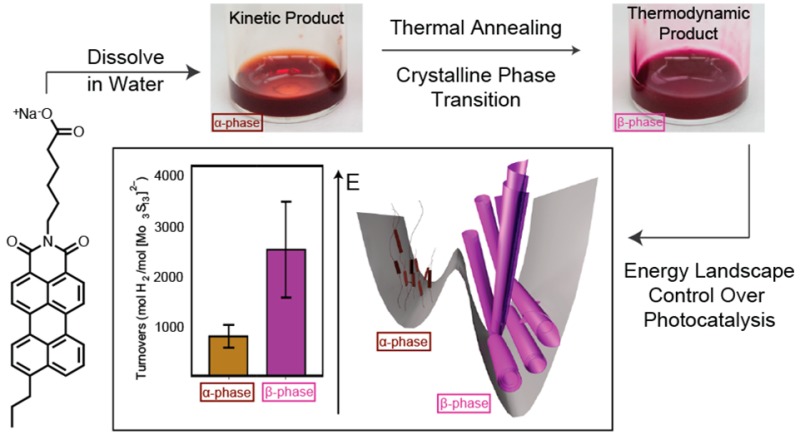
The energy landscape of a supramolecular material can include different molecular packing configurations that differ in stability and function. We report here on a thermally driven crystalline order transition in the landscape of supramolecular nanostructures formed by charged chromophore amphiphiles in salt-containing aqueous solutions. An irreversible transition was observed from a metastable to a stable crystal phase within the nanostructures. In the stable crystalline phase, the molecules end up organized in a short scroll morphology at high ionic strengths and as long helical ribbons at lower salt content. This is interpreted as the result of the competition between electrostatic repulsive forces and attractive molecular interactions. Only the stable phase forms charge-transfer excitons upon exposure to visible light as indicated by absorbance and fluorescence features, second-order harmonic generation microscopy, and femtosecond transient absorbance spectroscopy. Interestingly, the supramolecular reconfiguration to the stable crystalline phase nanostructures enhances photosensitization of a proton reduction catalyst for hydrogen production.
Introduction
Self-assembly of amphiphilic molecules has proven to be a facile, bottom-up route to highly functional supramolecular nanostructures and materials.1,2 While much is known about how molecular structure dictates assembly under spontaneous thermodynamic control,3,4 much less known are the energy landscapes and corresponding barriers of supramolecular systems under kinetic control.5−8 Indeed, systems in which pathway complexity exists can gives rise to supramolecular structures and functions other than those possible under thermodynamic control. Examples include formation of novel molecular interfaces9 and direct control of supramolecular polymerization in porphyrin,10,11 perylene,12 and corannulene systems.13 In this context, the existence of crystallinity and transformations in crystalline order within amphiphilic supramolecular nanostructures is unusual.14−17 The crystalline order that is so common in metals and inorganic semiconductors leading to band formation and electron delocalization would be highly beneficial in functional light-absorbing supramolecular systems.
We reported recently on a new class of light-absorbing, crystalline supramolecular polymers based on the self-assembly of chromophore amphiphiles (CAs) in water.14,18 These amphiphiles, composed of a perylene monoimide (PMI) core covalently linked to a carboxylate group via a spacer, were found to assemble into highly charged ribbon-like supramolecular nanostructures. In order to balance strong molecular attraction and electrostatic repulsion, the molecules pack in an antiparallel configuration and form a monolayer with charged groups on either side of the nanostructure. These charged assemblies in aqueous solution formed a light-absorbing soft gel when exposed to electrolytes as a result of charge screening. Addition of salt to charged amphiphiles can have a variety of effects, including gelation,19,20 morphological transitions,21,22 interassembly reorganization,23−25 and formation of novel materials.26,27 Interestingly, we found that the gelation of our PMI amphiphiles with salt results in crystallization within the supramolecular assemblies as charge screening allows the charged molecules pack closer in the absence of strong repulsive electrostatic forces (see Figure S3 for schematic of molecular packing). Importantly, charge screening of the nanostructures also leads to hydrogel formation. While gels and crystals are often thought of as incongruent states, it is important to note that in our previously reported system crystallinity and gelation occur on different length scales; we observed charged nanostructures with crystalline order that themselves form hydrogels upon charge screening.14 When a proton reduction catalyst of opposite charge to the light absorbing, nanoscale ribbons is encapsulated in the soft hydrogel, one observes hydrogen production upon illumination.14,18 This system demonstrated the possibility of using supramolecular chemistry to design photocatalytic materials.
Photocatalysis in the gel described above suggested that different crystalline phases within the light-absorbing nanostructures could modify photocatalytic function. This difference makes sense since the structural details of molecular packing among chromophores within a solid can determine intermolecular electronic coupling. This will determine in turn the light-harvesting potential of the supramolecular structures. We found previously that modifications to the alkyl linker on the PMI CAs led to differences in crystallinity and catalytic performance.18 Motivated by these results, we proceeded to explore how the substitution of PMI’s 9-postion with alkyl tails alters molecular packing within the nanoscale 2D crystals. We synthesized and studied in this work the self-assembly behavior of a CA with a propyl tail at the 9-position of PMI (T3-PMI, Figure 1A; see the Supporting Information for synthetic details).
Figure 1.
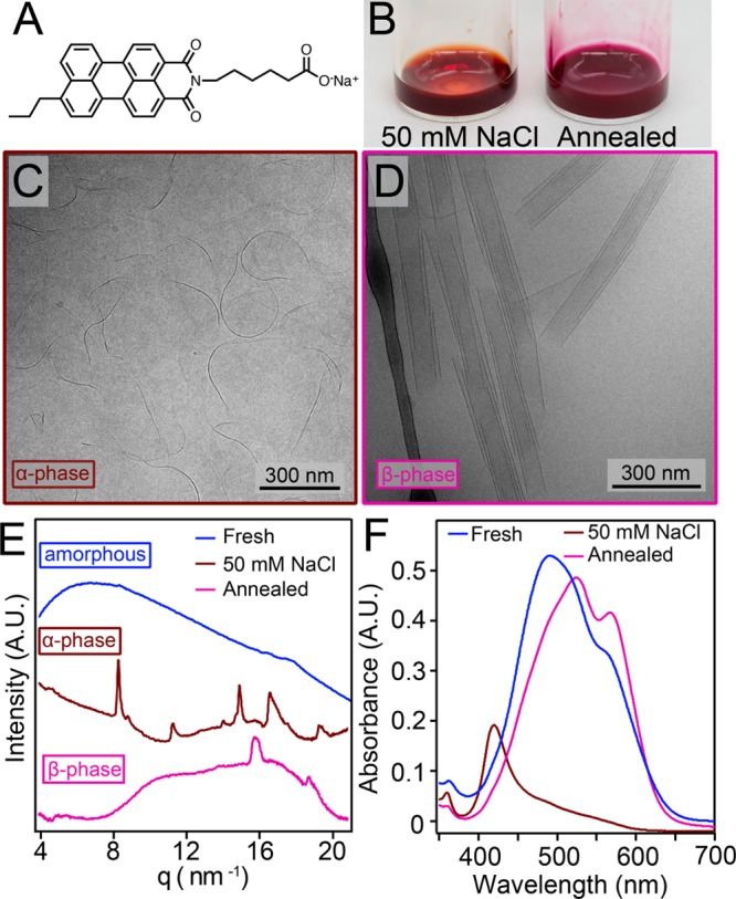
(A) Molecular structure of T3-PMI chromophore amphiphile. (B) Photographs of 7.25 mM T3-PMI solution with 50 mM NaCl before (left) and after (right) annealing. (C) Cryo-TEM of 7.25 mM T3-PMI with 50 mM NaCl shows ribbons that are 15 ± 4 nm in width. (D) Cryo-TEM of annealed T3-PMI solution reveals scrolls of 90 ± 13 nm in width. (E) WAXS patterns of freshly dissolved, 50 mM NaCl, and annealed solution of T3-PMI. Freshly dissolved pattern shows no peaks, 50 mM NaCl (α-phase) pattern shows peaks at 8.3, 11.2, 14.9, 16.5, and 19.3 nm–1, and annealed (β-phase) pattern shows peaks at 15.7 and 18.6 nm–1. (F) Absorbance spectroscopy of freshly dissolved T3-PMI shows an absorbance maximum at 490 nm and a shoulder at 558.5 nm, 50 mM NaCl (α-phase) shows a blue-shifted absorbance maximum at 420 nm, and the annealed (β-phase) shows an absorbance maximum at 523 nm with a new feature at 565 nm.
Previous work in our laboratory has shown that supramolecular systems have energy landscapes in which pathways followed in their formation affect the nature of molecular packing and their potential functions.5,19 One strategy that proved useful was thermal annealing to promote short-range intermolecular attractive forces in charged amphiphiles under charge-screening conditions that diminish electrostatic repulsive forces. Following this strategy, we discovered that nanostructures formed through self-assembly of T3-PMI can transition between two different crystalline structures upon thermal annealing and that supramolecular morphology could be affected by the extent of electrostatic screening.
Results and Discussion
Freshly dissolved solutions of T3-PMI in water (8.7 mM) were deep red in color and displayed ∼200 nm long 1D nanostructures by cryogenic transmission electron microscopy (cryo-TEM) (Figure S4). Wide-angle X-ray scattering (WAXS) of freshly dissolved solutions showed no diffraction peaks (Figure 1E). These data indicate that while the CAs are assembled, the nanostructures do not possess any crystalline domains consistent with previously reported CAs.14 Upon addition of NaCl to a final salt concentration of 50 mM, we observed a color change from red to pale orange (Figure 1B left). Cryo-TEM of 50 mM NaCl T3-PMI solutions revealed ∼400 ± 90 nm long ribbons that were 15 ± 4 nm wide (see Figure 1C and Figure S5A for ribbon width histogram). A similar morphology was observed by atomic force microscopy (AFM) after spin-casting the solution onto a glass substrate (Figure S6). WAXS of 50 mM NaCl T3-PMI solutions revealed diffraction peaks at 8.3, 11.2, 14.9, 16.5, and 19.3 nm–1 (Figure 1E, brown trace), indicating the formation of a crystalline lattice under charge-screening conditions (referred to here as the “α-phase”). A similar scattering pattern is observed when T3-PMI was charge screened by CaCl2 (Figure S7). Charge screening by the cations in solution reduces the electrostatic repulsion among the headgroups, allowing the molecules to pack into a crystalline lattice via strong intermolecular attractive forces. By indexing the diffraction peaks, we determined that the crystal structure had a 2D oblique unit cell with parameters shown in Figure 2A (see Figure S8 for WAXS fitting). Notably, some of the molecules in this lattice are oriented nearly perpendicular to each other (see Figure 2A), a configuration that would limit orbital overlap in this crystal and likely lead to lattice strain. This in turn could explain the narrow width of the supramolecular nanostructures.
Figure 2.
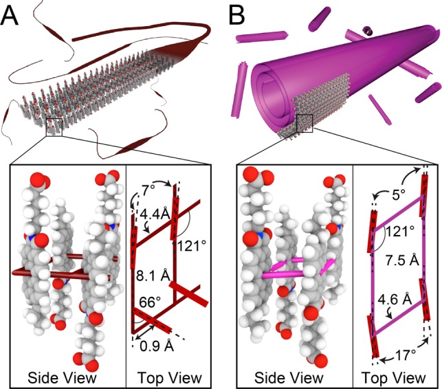
Schematic representation of (A) α-phase and (B) (β-phase) nanostructures including side and top views of the molecular basis that occupies one quadrant of the oblique unit cell.
We found that upon heating the solution to 80 °C and cooling at 0.3 °C/min the T3-PMI solution becomes dark purple (Figure 1B right). Examination of this solution by cryo-TEM revealed that the short, narrow ribbons had transformed into much larger scroll-like structures with outer diameters of 90 ± 13 nm (see Figure 1D and Figures S5B and S9 for size histogram and additional cryo-TEM). This scroll morphology was confirmed by AFM conducted on drop-cast samples (Figure S10). Variable-temperature dynamic light scattering (VT-DLS) experiments showed a sharp increase in signal intensity between 50 and 60 °C, confirming the drastic change in size between the two morphologies (Figure S5C). Along with this morphological transition, we observed a new set of diffraction peaks at 15.7 and 18.6 nm–1 in the WAXS pattern of annealed T3-PMI (Figure 1E, pink trace), referred to as the “β-phase”. The differences in X-ray scattering between the two supramolecular structures were supported by grazing incidence wide-angle X-ray scattering (GIWAXS) experiments using CA solutions dropcast onto glass slides (see Figure S11). We observed highly anisotropic scattering features from both lattices (indicating crystallinity within the nanostructure lying flat on the substrate) that closely matched the solution-phase X-ray traces. The new scattering peaks in the β-phase were fit to a diffraction model of an oblique unit cell (Figure 2B and see Figure S8 for peak fitting). In this new unit cell, the CA molecules align with each other, which can maximize π-orbital overlap and thus increase the nanostructure’s width.
We believe that addition of salt to screen charges on aggregates of CA molecules rapidly induces crystallization into the α-phase. We hypothesize that in this crystalline phase steric interactions among propyl segments and the imide side chains initially forces the molecules to adopt a kinetically trapped packing arrangement, preventing them from forming extended 2D supramolecular assemblies. However, thermal energy enables the transition of the supramolecular α-phase to the more thermodynamically favorable β-phase. In the crystalline β-phase, molecules reorient to maximize π-orbital overlap. We propose that the curvature of the scrolled 2D structures likely optimizes molecular packing for π overlap, hydrophobic contacts, and diminished sterics.
The observed color difference of solutions containing supramolecular nanostructures with the two distinct crystal structures strongly suggested that the packing arrangement directly influences the nanostructure’s excitonic properties. Transition dipole moment coupling in molecular aggregates produces the blue and red spectral shifts typically seen in H- and J-aggregates, respectively.28,29 In organic crystals, a second type of coupling can be accessed when the chromophore’s frontier orbitals couple along a crystalline axis. This short-range, charge-transfer (CT) coupling mediates electron and hole sharing via wave function overlap among adjacent chromophores.30−32 Upon light absorption, the local molecular Frenkel excitations (FE states) can mix with higher energy CT states to form hybrid FE/CT states.33 In organic crystals these states are known as CT-excitons and have been used to explain the appearance of new ground-state absorbance features that arise upon chromophore crystallization.34 Furthermore, recent theoretical studies conducted on PMI-based CA crystals have shown that the large dielectric environment surrounding the crystal effectively screens the electrostatic attraction between the exciton’s electron and hole, producing extended CT excitons (excitons where the electron and hole reside two or more lattice sites away from one another) that play a key role in explaining the crystal’s ground-state absorption spectrum.35
In the present system, absorbance spectroscopy of freshly dissolved T3-PMI showed an absorbance maximum (λmax) at 490 nm and a shoulder at 559 nm (Figure 1F). This spectrum is typical of H-aggregated (cofacially stacked), noncrystalline PMI aggregates.14 Upon crystallization into the α-phase, we observed a blue shift of the λmax to 420 nm and a decrease in oscillator strength (Figure 1F), as we previously reported.14 This spectral shift indicates formation of vibrationally decoupled excitons in highly H-aggregated assemblies.36 The decrease in oscillator strength is consistent with the symmetry of transition dipoles in the crystal. The reason is that the CA molecules are arranged antiparallel to one another, and the optically bright exciton state where all of the CA transitional dipoles are in resonance occurs at k = π, thus yielding a weakly absorbing indirect band gap semiconductor (see Figure S12 for further details). Upon annealing the charge-screened T3-PMI solution, we observed a stronger absorbance with λmax = 523 nm and the appearance of a new absorption feature at 565 nm (Figure 1F). The appearance of the 565 nm band has been assigned to CT excitons based on a previous assignment in PDI crystals37,38 and to extended CT-exciton states in PMI-based crystals.35 The absence of this spectroscopic feature in absorption by the α-phase and the monomer indicates it is unique to molecular packing associated with the β-phase (see absorbance spectra in Figure S13).
Given that H-aggregated assemblies are indirect semiconductors, the reappearance of high oscillator strength in β-phase crystals is likely due to CAs’ transition dipole moments no longer canceling each other out. This could arise from either a structural slip of the molecular packing or a change in the polarization direction of the chromophore’s transition dipole moments. Such a change in polarization could be due to CT-exciton formation as CT-excitons are known to reorient the transition dipole polarization away from the main axis of the molecule,34,39 which in this case would result in less oscillator dampening at k = 0 and higher absorbance intensities. If CT-excitons were being formed, excimer-like fluorescence should be observed, as mixing of molecular excitations (FE states) with CT states in π-stacked chromophore dimers leads to excimer formation.40,41 Indeed, β-phase fluorescence showed an emission maximum at 652 nm (Figure S14), in excellent agreement with excimer emission (649 nm) from PMI dimers covalently bound in an antiparallel stacking arrangement.41 Emission of amorphous and α-phase aggregates is highly quenched relative to β-phase assemblies. After normalizing for absorbance intensity at the excitation wavelength, we see that β-phase assemblies produce roughly seven times more emission than either the amorphous or α-phase aggregates. Given that excited state emission in H-aggregated assemblies should be highly quenched, these emission data suggest that the lowest energy excited state of β-phase crystals distinct from both the amorphous and α-phase assemblies due to its strong radiative coupling to the ground state. These data suggest that the phase transition greatly alters the excited state formed in CA crystals, likely through changes in the electron- and hole-transfer integrals that are highly sensitive to molecular packing.34,42 Furthermore, comparison of absorbance spectra for the α and β phases demonstrates a clear crystallochromic effect whereby optical properties determined by the quantum mixing of FE and CT states depend directly on the details of molecular packing arrangement.
We carried out solution-phase variable-temperature (VT) X-ray scattering experiments in order to directly connect the crystal-phase transition to the appearance of the 565 nm CT-exciton feature. Heating a 50 mM NaCl T3-PMI solution at 1 °C/min, we observed the α-phase scattering pattern up to 50 °C in the wide-angle region (3–30 nm–1) (see Figure 3A and the SI for experimental details). The β-phase began to appear at 53 °C (see feature at 16.0 nm–1) and became the dominant phase as the temperature was raised further. Analysis of peak area versus temperature showed that the disappearance of the 8.3 nm–1 peak was directly correlated with the appearance of the 16.0 nm–1 peak (Figure 3B and Figure S15). Additionally, in the small angle region (0.02–2 nm–1) we observed for the α-phase scattering curve (as a function of scattering vector q) a slope of −2, which is consistent with our observation of ribbons rather than purely one-dimensional structures by electron microscopy. Upon reorganization of molecules into the β-phase, we observed a minimum in the scattering curve at a q vector of 0.07 nm–1. This minimum is in agreement with the appearance of the scrolled structures measuring 90 nm in their outer diameter. Monitoring this transition by VT absorbance spectroscopy (VT UV–vis) at 565 nm, we observed a sharp increase in intensity between 50 and 60 °C upon heating at 1 °C/min (Figure 3C, red curve) and no further change upon cooling (Figure 3C, blue curve). The correlation in transition temperature and stability upon cooling between the VT X-ray and VT UV–vis experiments confirms that the CT-exciton feature appears as a direct result of β-phase formation (see Figure 3B and Figure S16 for X-ray cooling traces).
Figure 3.
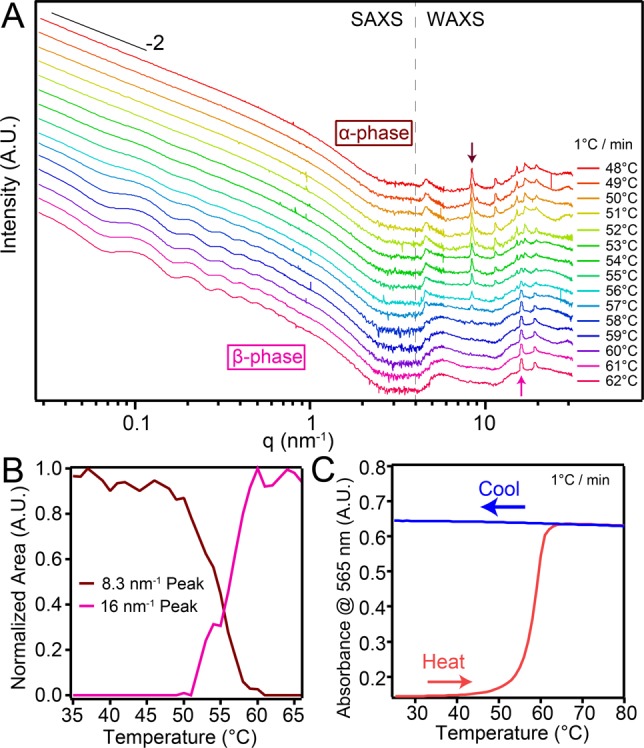
(A) VT X-ray scattering of 7.25 mM T3-PMI solution with 50 mM NaCl. Samples were heated at 1 °C/min and data collected every minute. (B) Normalized intensity vs temperature plots for the 8.3 and 16 nm–1 peaks in (A). (C) VT absorbance spectroscopy of 50 mM NaCl T3-PMI solution in a 50 μm demountable cuvette monitored at 565 nm. Temperature was ramped at 1 °C/min.
This correlation between the X-ray scattering and absorbance experiments further allowed us to use VT UV–vis to determine phase-transition kinetics. In order to determine the activation energy (Ea), isothermal heating absorbance experiments were carried out at various temperatures and normalized for the degree of conversion, x(t) (Figure 4A).43−45 An Arrhenius-type analysis of the data yielded a linear plot (Figure 4B), the slope of which gives Ea = 125 kJ/mol (see the Supporting Information for kinetic model details). Differential scanning calorimetry (DSC) revealed a sharp, exothermic peak around the transition temperature observed by other techniques (Figure 4C), and the curve was used to determine the enthalpy of transition (ΔH). Integrating the area under this peak yielded ΔHtransition = −4.4 kJ/mol. Additional entropic components to the phase transition’s driving force likely arise from a rearrangement of water molecules as a result of the morphological change. The energy values for kinetic barrier height and Gibbs free energy change have been summarized in an energy landscape diagram (see Figure 4D) where a barrier of height Ea (125 kJ/mol or 50 kBT) is sufficiently high to trap the stable α-phase from the thermodynamically more favored stable β-phase.
Figure 4.
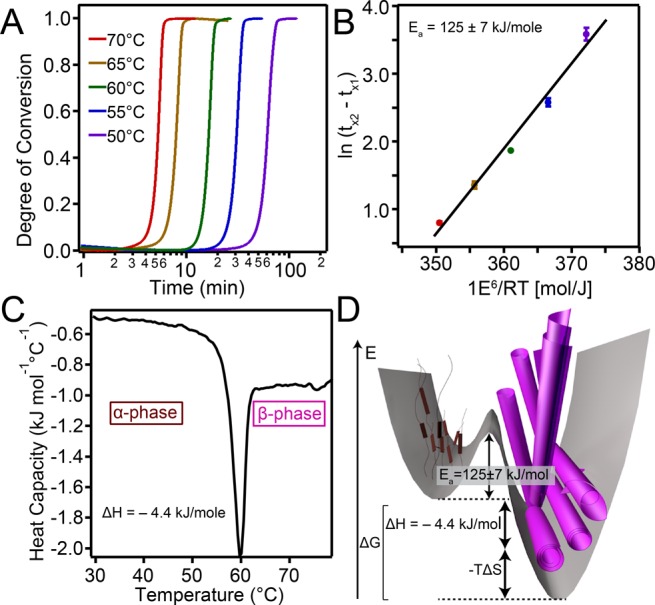
(A) Isothermal heating curves 7.25 mM T3-PMI solution with 50 mM NaCl monitored at 565 nm. (B) Plot to determine activation energy using eq 1 in the SI. (C) DSC of 7.25 mM T3-PMI solution with 50 mM NaCl heated at 1.5 °C/min. (D) Energy landscape diagram of T3-PMI phase transition at 50 mM NaCl (not drawn to scale).
β-Phase formation likely occurs via a nucleation and growth mechanism. In contrast to porphyrin systems that show full dissolution of one morphology during phase transition,11 the α-phase remains intact and is gradually depleted as observed in data shown in Figure 3B. The presence of the α-phase during β-phase nucleation suggests that nuclei can form via either rearrangement of the molecules within the α-phase or association of disordered aggregates present in solution. Unfortunately, the available data do not allow us to exclude either of these possibilities. The variable-temperature data do show β-phase growth as a consequence of α-phase depletion, suggesting that monomers or small disordered aggregates are transferred from the α-phase to the growing β-phase. The dramatic size increase and regularity of the β-phase nanostructures supports further this molecular exchange pathway. Recent experiments from our laboratory on assemblies of other charged amphiphilic molecules have shown that the exchange of small aggregates between nanostructures built by charged amphiphilic molecules is possible.46 We therefore propose that such an exchange is a feasible pathway for crystal growth once nucleation occurs.
We discovered that the ionic strength of the solution strongly influences the nucleation and growth kinetics of the β-phase and the morphology of the nanostructures as well (Figure 5A). As shown in Figure 5A, path 1 represents annealing T3-PMI in 50 mM NaCl, whereas path 2 represents annealing in 1 mM NaCl. Annealing T3-PMI along either path results in identical WAXS and absorbance spectra (Figure S17A,B), indicating crystallinity is retained under these low salt conditions. However, fluorescence confocal microscopy showed that the two paths have dramatically different micron scale structures; path 1 produced short assemblies (Figure 5B), consistent with the short scrolls (referred to here on as βscroll) observed by cryo-TEM and AFM (Figure 1D, and Figure S10, respectively), whereas path 2 produced much longer assemblies, some of which exceed 20 μm in length (Figure 5C). Cryo-TEM and AFM confirmed the formation of long 1D assemblies (Figure 5D and E, respectively, and additional images in Figure S18) and revealed their identity as helical ribbons (referred to here on as βhelix). The two β-phase morphologies are certainly related; we hypothesize that the curvature found in these structures is connected to an optimal molecular packing configuration of the β-phase unit cell formed by these crystalline nanostructures. However, altering the salt concentration during annealing clearly changes the growth mechanism of the newly formed β-phase. One unknown detail is the possible presence of amorphous and 2D crystalline regions within the aggregates which would require very challenging future work
Figure 5.
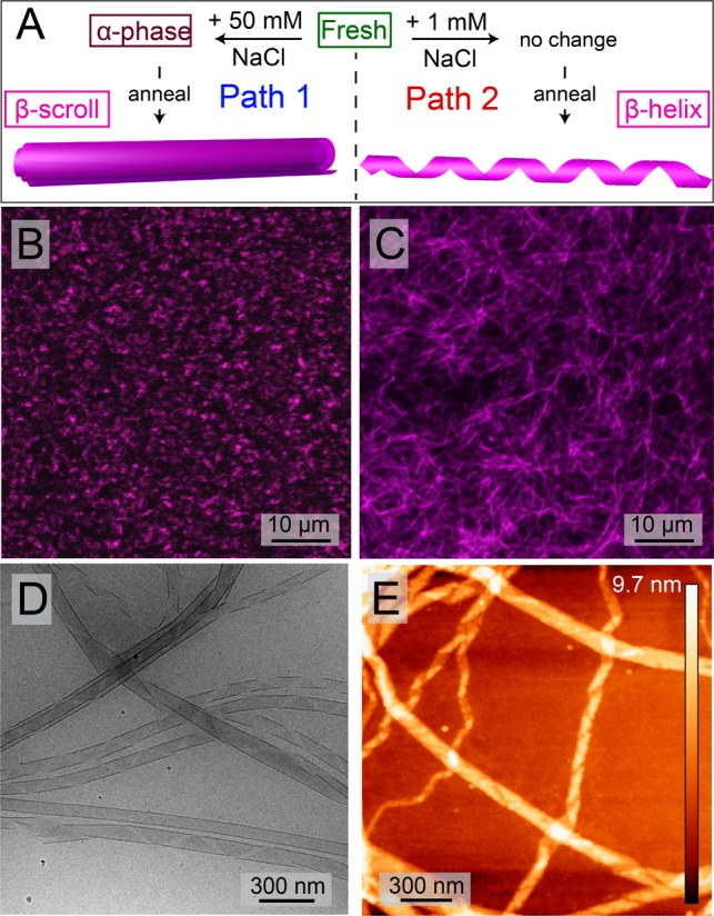
(A) Schematic diagram describing the two pathways for annealing T3-PMI solution. Confocal microscopy of annealed aggregates formed under path 1 (B) and path 2 (C). Cryo-TEM (D) and AFM (E) of helical aggregates formed in path 2.
Investigating the growth of these helical assemblies along path 2 by VT UV–vis showed little change in intensity at 565 nm upon heating (Figure S17C). Instead, a dramatic increase in absorbance intensity was observed when path 2 samples were cooled from 80 °C (Figure S17C and Figure 6A). This transition was correlated with an increase in scattering intensity as seen by VT-DLS (Figure 6A) corresponding to the growth of 1-D helical nanostructures. In contrast to the first order transition observed upon heating with 50 mM NaCl (path 1), the nucleation and growth of these crystalline helices occurred only upon cooling. Furthermore, the nucleation temperature is roughly 30 °C higher for path 2 than for path 1, indicating a larger kinetic barrier to crystallization. Our observations suggest that the increasing intermolecular charge repulsion as the β phase grows is balanced by attractive forces among molecules differently along the two crystallographic directions. That is, at a high salt concentration (50 mM NaCl; path 1), crystal growth occurs in both crystallographic directions because strong screening balances both the strong and weak attractive forces parallel and perpendicular to the ribbon axis, respectively. However, at lower salt concentration (1 mM NaCl; path 2), charge accumulation during crystal growth is only balanced by the strong forces parallel to the ribbon axis, producing long 1-D assemblies. This charge accumulation likely produces a larger kinetic barrier for nuclei formation in path 2, leading to the 30° increase in the required temperature for nucleation and growth. As the scrolls and helices are formed in their respective energy landscapes, we do not expect interconversion from long helices to short scrolls to be possible (see Figure S17D for energy landscape summary). Indeed, reannealing the 1-D helices in the presence of 50 mM NaCl produces nanostructures that are an intermediate state between helices and scrolls (Figure S17E,F), further suggesting that charge screening allows crystal growth in the lateral direction. Furthermore, our results are consistent with our previous observation that energy landscapes in supramolecular systems are efficiently navigated by identification of the dominant interactions and then establishing how the environment around the supramolecular structure can be altered to switch on and off the important interactions.5 In the system investigated here, switching off electrostatic interactions alters the crystallization pathway, resulting in nanostructures with morphologies that depend on the extent of screening of repulsive interactions among the charged molecules.
Figure 6.
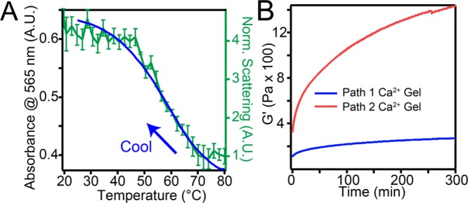
(A) Variable-temperature absorbance spectroscopy (left axis) and DLS (right axis) of cooling path 2 solution from 80 °C at 1 °C/min. (B) Rheology of CaCl2 gels of annealed aggregates formed in both paths.
Finally, we explored how morphological differences between short scrolls and helices affected mechanical properties of hydrogels formed in the presence of CaCl2 due to electrostatic attraction among negatively charged nanostructures. When these assemblies were gelled with CaCl2 (15 μL, 150 mM CaCl2 added to 170 μL 8.7 mM T3-PMI), solutions of βhelix nanostructures produced gels that were 5.3 times stiffer than those formed from βscrolls (see Figure 6B). This finding indicates that while the crystalline nanostructures formed by the supramolecular structures through paths 1 and 2 have the same unit cells and electronic properties, the solution’s ionic strength can be used also to tune nanostructure’s dimensionality and size, thereby altering the macroscopic mechanical properties of the resulting hydrogels.
We investigated how the change in the crystals exciton properties associated with a crystal-to-crystal phase change affected photocatalytic H2 production. We synthesized a thiomolybdate cluster [Mo3S13]2– reported recently to be an active proton reduction catalyst (Figure 7A top inset and Figure S19).47 We found that when β-phase supramolecular helices (βhelix) of T3-PMI molecules were illuminated in the presence of the [Mo3S13]2– catalyst and ascorbic acid (as sacrificial electron donor), the catalyst turned over 2600 ± 880 times in 18 h, producing 210 ± 70 μL of H2 (Figure 7A). Furthermore, we observed continuous H2 production from βhelix samples over the course of >100 h, yielding a maximum of 11100 turnovers (Figure 7A bottom inset). Control experiments without the supramolecular structures formed by CA molecules, catalyst, ascorbic acid, or light only yielded negligible H2 production (Figure 7A), indicating that T3-PMI supramolecular structures photosensitize the [Mo3S13]2– clusters in our experiments (Figure 7B). Interestingly, we found that β-phase scrolls (βscroll) yielded 1900 ± 530 turnovers (Figure 7C), a similar value to the βhelix which is expected as both the βhelix and βscrolls assembled into same crystal packing arrangement. We next tested the differences in photochemical performance based on the nature of the crystalline phase within the nanostructures. Interestingly, under identical conditions, we observed approximately a 3-fold enhancement in H2 production when β-phase nanostructures were present as the light absorbers compared to α-phase nanostructures (790 ± 230 TON after 18 h). In previous experimental and theoretical work, CAs crystal phases capable of generating CT-excitons showed enhanced H2 production efficiencies even when the data were normalized for spectral overlap with the illumination source.35 We hypothesize a similar phenomenon is responsible for the enhancement in H2 observed here as only the β-phase assemblies are able to support CT exciton formation and so produce more H2.
Figure 7.

(A) Hydrogen production experiments with T3-PMI and Mo3S132– proton reduction catalyst (inset, top). Continuous H2 production was carried out over 100+ hours (inset, bottom). (B) Hydrogen production with β-phase helicies and scrolls compared to α-phase structures in the presence of the Mo3S132– catalyst. All solutions were gelled with 20 μL of 5 wt % PDDA before sample preparation. (Inset) Photographs of β-phase (left) and α-phase (right) PDDA gels. (C) Schematic of photoinduced electron transfer from T3 helical ribbons to catalytic clusters.
In CT-excitons, the electrons and holes are separated across multiple molecules resulting in a lower exciton binding energy, enhanced exciton mobility, and larger exciton radius.34,37,42 The large static dipole moment created in such excitations can lead to large second-order nonlinear polarizabilities.37 In order to probe the presence of CT-exciton in β-phase assemblies, lattice polarizability of the nanostructures was studied by second-order harmonic generation (SHG) microscopy (see Figure S20 for details). Samples were excited with two 850 nm photons, and emission was recorded between 350 and 450 nm. We found that β-phase assemblies showed substantially greater SHG signals (see Figure 8A and Figure S21) than those containing the α-phase (Figure 8B and Figure S22). We believe that the observed signal arises from an excited state noncentrosymmetric distribution of electron density within the material because singlet-excited-state emission at 550–750 nm is also observed (Figure S22). Interestingly, these visible photons can be reabsorbed by β-phase assemblies, thereby facilitating the creation of additional CT-excitons and further SHG emission during the experiment. While an SHG signature is not direct evidence of CT-exciton formation, it does suggest a noncentrosymmetric distribution of electron density in the β-phase lattice that is typically associated with CT-excitons.
Figure 8.
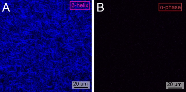
SHG microscopy of (A) β-phase helixes (B) and α-phase nanostructures.
As mixing of the FE and CT states occurs after excitation, the β-phase assemblies should show different excited-state dynamics than those observed in the α-phase or the monomer. Femtosecond transient absorbance (fsTA) spectroscopy of β-phase crystalline nanostructures showed a rapid decay of the excited state signal in 15 ps (Figure 9A). As the excited-state lifetime of T3-PMI dissolved in 6:1 CHCl3/MeOH solution (near monomeric state) is ∼5 ns (see Figure S23), we interpret this rapid signal decay as a redistribution of Frenkel state oscillator strength to the intrinsically low-oscillator strength CT-state.37 While we were unable to extract what fraction of the population survives to this final state, the broad feature in the near IR did give us information about excimer dynamics in the system. For both α- and β-phase crystals, the absorbance feature in the visible region decays faster than the NIR feature, suggesting a possible cascade of singlet excited state to excimer-like state. Interestingly, this cascade occurs much faster in β-phase crystals, suggesting that a third state is produced on time scales shorter than that of emission. Furthermore, we observed an absorption feature in the near-IR at 1470 nm for the β-phase and at 1580 nm for the α-phase (part A and B, respectively, of Figure 9). Such a feature has previously been assigned to the transition from an excimer state to a radical-pair state and yields information about the strength of intermolecular coupling.40,41 The larger transition energy in the β-phase further confirms a stronger intermolecular coupling in β-phase CAs relative to those in the α-phase. While we did not observe the appearance of any new spectral features that could directly be assigned to a CT-exciton state (possibly due to their low intrinsic oscillator strength), these data do suggest that crystalline packing directly impacts the energy flow mechanisms in crystalline CA assemblies.
Figure 9.
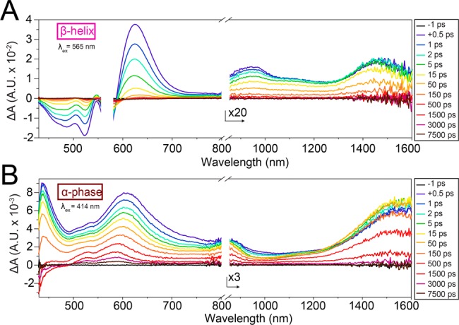
Femtosecond transient absorption spectra of β-phase helices (A) and α-phase nanostructure (B). β-Phase was excited at 565 nm, while the α-phase was excited at 414 nm.
The absorbance, emission, SHG, and fsTA data suggest that excitation of β-phase crystalline supramolecular polymers produces an excited state that is unique compared to either the α-phase or the amorphous aggregates. Furthermore, the appearance of new absorbance features and SHG signals in β-phase crystals is suggestive of the formation of a CT-exciton upon excitation. While computational details about electron/hole transfer integrals and exciton separation distances are beyond the scope of this work, the observed correlation between CT-exciton formation and faster rates of hydrogen production are consistent with theoretical predictions of that preseparation of electron and hole and their separation across a crystalline domain makes the electron more assessable for transfer to a proton reduction catalyst.35
Conclusion
We have found that supramolecular nanostructures of chromophore amphiphiles formed by self-assembly in water undergo a thermal phase transition between two unique crystalline states that is accompanied by changes in the nature of excitons created by light absorption. The electronic properties of these crystalline supramolecular polymers have been found to depend on the structure of their crystalline lattice. Since the monomeric units are charged, we observed a dependence of the nucleation and growth of the thermodynamic stable crystalline phase on the ionic strength. When placed into contact with an inorganic proton-reduction catalyst, we observed enhanced rates of H2 production in systems containing nanostructures with the most stable crystalline phase, which is capable of creating CT excitons. Since the electronic properties of these supramolecular nanostructures can be altered by slight modifications in crystal packing arrangements, we believe a large phase space can be discovered that can be used to optimize photosensitization of catalysts through molecular design of the self-assembling chromophores.
Acknowledgments
This work was supported as part of the Argonne–Northwestern Solar Energy Research (ANSER) Center, an Energy Frontier Research Center funded by the U.S. Department of Energy, Office of Science, Basic Energy Sciences under Award No. DE-SC0001059. AFM, SHG, and powder XRD experiments were also supported by the Office of Science, Basic Energy Sciences, Materials Sciences and Engineering Division, of the U.S. Department of Energy under Award No. DE-FG02-00ER45810. Use of the Advanced Photon Source (APS) was supported by the U.S. Department of Energy, Office of Science, Basic Energy Sciences, under Contract No. DE-AC02-06CH11357. Variable-temperature X-ray experiments were performed at the DuPont–Northwestern–Dow Collaborative Access Team (DND-CAT) located at Sector 5 of the Advanced Photon Source (APS). DND-CAT is supported by Northwestern University, E.I. DuPont de Nemours & Co., and The Dow Chemical Company. This research used resources of the Advanced Photon Source, a U.S. Department of Energy (DOE) Office of Science User Facility operated for the DOE Office of Science by Argonne National Laboratory under Contract No. DE-AC02-06CH11357. WAXS experiments conducted at BioCARS Sector 14 at the APS were supported by grants from the National Center for Research Resources (5P41RR007707) and the National Institute of General Medical Sciences (8P41GM103543) from the National Institutes of Health. GIXS data were collected at Sector 8-ID-E of APS. We thank the Biological Imaging Facility (BIF) at Northwestern for the use of TEM equipment, the Electron Probe Instrumentation Center (EPIC) and Keck-II facilities of the Northwestern University Atomic and Nanoscale Characterization Experimental (NUANCE) center for the use of SEM and XPS/UPS equipment. NMR and MS equipment at the Integrated Molecular Structure Education and Research Center (IMSERC) was supported by the National Science Foundation under CHE-9871268. The NUANCE Center is supported by the International Institute for Nanotechnology, MRSEC (NSF DMR-1121262), the Keck Foundation, the State of Illinois, and Northwestern University. The energy landscape analysis was supported by by the Center for Bio-Inspired Energy Sciences (CBES), an Energy Frontiers Research Center (EFRC) funded by the US Department of Energy, Office of Science, Office of Basic Energy Sciences under award number DE-SC0000989.
Supporting Information Available
The Supporting Information is available free of charge on the ACS Publications website at DOI: 10.1021/jacs.6b13156.
Experimental methods, materials used, synthetic characterization, calculations, and data (PDF)
Author Present Address
& (J.B.) Institute for Advanced Study and Department of Chemistry, Technische Universität München, 85748 Garching, Germany.
The authors declare no competing financial interest.
Supplementary Material
References
- Aida T.; Meijer E. W.; Stupp S. I. Science 2012, 335, 813. 10.1126/science.1205962. [DOI] [PMC free article] [PubMed] [Google Scholar]
- Stupp S. I.; Palmer L. C. Chem. Mater. 2014, 26, 507. 10.1021/cm403028b. [DOI] [Google Scholar]
- Zang L.; Che Y.; Moore J. S. Acc. Chem. Res. 2008, 41, 1596. 10.1021/ar800030w. [DOI] [PubMed] [Google Scholar]
- Würthner F.; Saha-Möller C. R.; Fimmel B.; Ogi S.; Leowanawat P.; Schmidt D. Chem. Rev. 2016, 116, 962. 10.1021/acs.chemrev.5b00188. [DOI] [PubMed] [Google Scholar]
- Tantakitti F.; Boekhoven J.; Wang X.; Kazantsev R. V.; Yu T.; Li J.; Zhuang E.; Zandi R.; Ortony J. H.; Newcomb C. J.; Palmer L. C.; Shekhawat G. S.; de la Cruz M. O.; Schatz G. C.; Stupp S. I. Nat. Mater. 2016, 15, 469. 10.1038/nmat4538. [DOI] [PMC free article] [PubMed] [Google Scholar]
- Korevaar P. A.; Schaefer C.; de Greef T. F. A.; Meijer E. W. J. Am. Chem. Soc. 2012, 134, 13482. 10.1021/ja305512g. [DOI] [PubMed] [Google Scholar]
- Endo M.; Fukui T.; Jung S. H.; Yagai S.; Takeuchi M.; Sugiyasu K. J. Am. Chem. Soc. 2016, 138, 14347. 10.1021/jacs.6b08145. [DOI] [PubMed] [Google Scholar]
- Korevaar P. A.; George S. J.; Markvoort A. J.; Smulders M. M. J.; Hilbers P. A. J.; Schenning A. P. H. J.; De Greef T. F. A.; Meijer E. W. Nature 2012, 481, 492. 10.1038/nature10720. [DOI] [PubMed] [Google Scholar]
- Zhang W.; Jin W.; Fukushima T.; Saeki A.; Seki S.; Aida T. Science 2011, 334, 340. 10.1126/science.1210369. [DOI] [PubMed] [Google Scholar]
- Fukui T.; Kawai S.; Fujinuma S.; Matsushita Y.; Yasuda T.; Sakurai T.; Seki S.; Takeuchi M.; Sugiyasu K. Nat. Chem. 2016, 10.1038/nchem.2684. [DOI] [PubMed] [Google Scholar]
- Ogi S.; Sugiyasu K.; Manna S.; Samitsu S.; Takeuchi M. Nat. Chem. 2014, 6, 188. 10.1038/nchem.1849. [DOI] [PubMed] [Google Scholar]
- Ogi S.; Stepanenko V.; Sugiyasu K.; Takeuchi M.; Würthner F. J. Am. Chem. Soc. 2015, 137, 3300. 10.1021/ja511952c. [DOI] [PubMed] [Google Scholar]
- Kang J.; Miyajima D.; Mori T.; Inoue Y.; Itoh Y.; Aida T. Science 2015, 347, 646. 10.1126/science.aaa4249. [DOI] [PubMed] [Google Scholar]
- Weingarten A. S.; Kazantsev R. V.; Palmer L. C.; McClendon M.; Koltonow A. R.; Samuel A. P. S.; Kiebala D. J.; Wasielewski M. R.; Stupp S. I. Nat. Chem. 2014, 6, 964. 10.1038/nchem.2075. [DOI] [PMC free article] [PubMed] [Google Scholar]
- Shahar C.; Baram J.; Tidhar Y.; Weissman H.; Cohen S. R.; Pinkas I.; Rybtchinski B. ACS Nano 2013, 7, 3547. 10.1021/nn400484y. [DOI] [PubMed] [Google Scholar]
- Nam K. T.; Shelby S. A.; Choi P. H.; Marciel A. B.; Chen R.; Tan L.; Chu T. K.; Mesch R. A.; Lee B.-C.; Connolly M. D. Nat. Mater. 2010, 9, 454. 10.1038/nmat2742. [DOI] [PubMed] [Google Scholar]
- Lohr A.; Lysetska M.; Würthner F. Angew. Chem., Int. Ed. 2005, 44, 5071. 10.1002/anie.200500640. [DOI] [PubMed] [Google Scholar]
- Weingarten A. S.; Kazantsev R. V.; Palmer L. C.; Fairfield D. J.; Koltonow A. R.; Stupp S. I. J. Am. Chem. Soc. 2015, 137, 15241. 10.1021/jacs.5b10027. [DOI] [PMC free article] [PubMed] [Google Scholar]
- Zhang S.; Greenfield M. A.; Mata A.; Palmer L. C.; Bitton R.; Mantei J. R.; Aparicio C.; de la Cruz M. O.; Stupp S. I. Nat. Mater. 2010, 9, 594. 10.1038/nmat2778. [DOI] [PMC free article] [PubMed] [Google Scholar]
- Roy S.; Javid N.; Frederix P. W.; Lamprou D. A.; Urquhart A. J.; Hunt N. T.; Halling P. J.; Ulijn R. V. Chem. - Eur. J. 2012, 18, 11723. 10.1002/chem.201201217. [DOI] [PubMed] [Google Scholar]
- Wu D.; Zhi L.; Bodwell G. J.; Cui G.; Tsao N.; Müllen K. Angew. Chem., Int. Ed. 2007, 46, 5417. 10.1002/anie.200700515. [DOI] [PubMed] [Google Scholar]
- Koti A.; Taneja J.; Periasamy N. Chem. Phys. Lett. 2003, 375, 171. 10.1016/S0009-2614(03)00866-2. [DOI] [Google Scholar]
- Leung C.-Y.; Palmer L. C.; Qiao B. F.; Kewalramani S.; Sknepnek R.; Newcomb C. J.; Greenfield M. A.; Vernizzi G.; Stupp S. I.; Bedzyk M. J.; Olvera de la Cruz M. ACS Nano 2012, 6, 10901. 10.1021/nn304321w. [DOI] [PubMed] [Google Scholar]
- Ortony J. H.; Newcomb C. J.; Matson J. B.; Palmer L. C.; Doan P. E.; Hoffman B. M.; Stupp S. I. Nat. Mater. 2014, 13, 812. 10.1038/nmat3979. [DOI] [PMC free article] [PubMed] [Google Scholar]
- Ohno O.; Kaizu Y.; Kobayashi H. J. Chem. Phys. 1993, 99, 4128. 10.1063/1.466109. [DOI] [Google Scholar]
- Wang C.; Guo Y.; Wang Y.; Xu H.; Wang R.; Zhang X. Angew. Chem., Int. Ed. 2009, 48, 8962. 10.1002/anie.200903897. [DOI] [PubMed] [Google Scholar]
- Capito R. M.; Azevedo H. S.; Velichko Y. S.; Mata A.; Stupp S. I. Science 2008, 319, 1812. 10.1126/science.1154586. [DOI] [PubMed] [Google Scholar]
- Kasha M.; Rawls H. Pure Appl. Chem. 1965, 11, 371. 10.1351/pac196511030371. [DOI] [Google Scholar]
- McRae E. G.; Kasha M. J. Chem. Phys. 1958, 28, 721. 10.1063/1.1744225. [DOI] [Google Scholar]
- Yamagata H.; Pochas C. M.; Spano F. C. J. Phys. Chem. B 2012, 116, 14494. 10.1021/jp309407r. [DOI] [PubMed] [Google Scholar]
- Brédas J. L.; Calbert J. P.; da Silva Filho D. A.; Cornil J. Proc. Natl. Acad. Sci. U. S. A. 2002, 99, 5804. 10.1073/pnas.092143399. [DOI] [PMC free article] [PubMed] [Google Scholar]
- Gisslén L.; Scholz R. Phys. Rev. B: Condens. Matter Mater. Phys. 2011, 83, 155311. 10.1103/PhysRevB.83.155311. [DOI] [Google Scholar]
- Yamagata H.; Norton J.; Hontz E.; Olivier Y.; Beljonne D.; Brédas J. L.; Silbey R. J.; Spano F. C. J. Chem. Phys. 2011, 134, 204703. 10.1063/1.3590871. [DOI] [PubMed] [Google Scholar]
- Gisslén L.; Scholz R. Phys. Rev. B: Condens. Matter Mater. Phys. 2009, 80, 115309. 10.1103/PhysRevB.80.115309. [DOI] [Google Scholar]
- Hestand N. J.; Kazantsev R. V.; Weingarten A. S.; Palmer L. C.; Stupp S. I.; Spano F. C. J. Am. Chem. Soc. 2016, 138, 11762. 10.1021/jacs.6b05673. [DOI] [PubMed] [Google Scholar]
- Spano F. C. Acc. Chem. Res. 2010, 43, 429. 10.1021/ar900233v. [DOI] [PubMed] [Google Scholar]
- Hoffmann M.; Schmidt K.; Fritz T.; Hasche T.; Agranovich V. M.; Leo K. Chem. Phys. 2000, 258, 73. 10.1016/S0301-0104(00)00157-9. [DOI] [Google Scholar]
- Haskal E.; Shen Z.; Burrows P.; Forrest S. Phys. Rev. B: Condens. Matter Mater. Phys. 1995, 51, 4449. 10.1103/PhysRevB.51.4449. [DOI] [PubMed] [Google Scholar]
- Agranovich V. M.Excitations in Organic Solids; Oxford University Press, 2009. [Google Scholar]
- Brown K. E.; Salamant W. A.; Shoer L. E.; Young R. M.; Wasielewski M. R. J. Phys. Chem. Lett. 2014, 5, 2588. 10.1021/jz5011797. [DOI] [PubMed] [Google Scholar]
- Lindquist R. J.; Lefler K. M.; Brown K. E.; Dyar S. M.; Margulies E. A.; Young R. M.; Wasielewski M. R. J. Am. Chem. Soc. 2014, 136, 14912. 10.1021/ja507653p. [DOI] [PubMed] [Google Scholar]
- Yamagata H.; Maxwell D. S.; Fan J.; Kittilstved K. R.; Briseno A. L.; Barnes M. D.; Spano F. C. J. Phys. Chem. C 2014, 118, 28842. 10.1021/jp509011u. [DOI] [Google Scholar]
- Moore D. T.; Sai H.; Tan K. W.; Smilgies D.-M.; Zhang W.; Snaith H. J.; Wiesner U.; Estroff L. A. J. Am. Chem. Soc. 2015, 137, 2350. 10.1021/ja512117e. [DOI] [PubMed] [Google Scholar]
- Liu F.; Sommer F.; Bos C.; Mittemeijer E. J. Int. Mater. Rev. 2007, 52, 193. 10.1179/174328007X160308. [DOI] [Google Scholar]
- Mittemeijer E. J. J. Mater. Sci. 1992, 27, 3977. 10.1007/BF01105093. [DOI] [Google Scholar]
- Da Silva R. M.; Van Der Zwaag D.; Albertazzi L.; Lee S. S.; Meijer E.; Stupp S. I. Nat. Commun. 2016, 7, 11561. 10.1038/ncomms11561. [DOI] [PMC free article] [PubMed] [Google Scholar]
- Kibsgaard J.; Jaramillo T. F.; Besenbacher F. Nat. Chem. 2014, 6, 248. 10.1038/nchem.1853. [DOI] [PubMed] [Google Scholar]
Associated Data
This section collects any data citations, data availability statements, or supplementary materials included in this article.


