Abstract
Surgeons and robots typically use different approaches for bone milling. Surgeons adjust their speed and tool incidence angle constantly, which enables them to efficiently mill porous bone. Surgeons also adjust milling parameters such as speed and depth of cut throughout the procedure based on proximity to sensitive structures like nerves and blood vessels. In this paper we use image-based bone density estimates and segmentations of vital anatomy to make a robot mill more like a surgeon and less like an industrial computer numeric controlled (CNC) milling machine. We produce patient-specific plans optimizing velocity and incidence angles for spherical cutting burrs. These plans are particularly useful in bones of variable density and porosity like the human temporal bone. They result in fast milling in non-critical areas, reducing overall procedure time, and lower forces near vital anatomy. We experimentally demonstrate the algorithm on temporal bone phantoms and show that it reduces mean forces near vital anatomy by 63% and peak forces by 50% in comparison to a CNC-type path, without adding time to the procedure.
I. Introduction
The value of robots in bone milling was recognized early in the history of surgical robotics (e.g. [1], [2]), and systems to assist with installing knee and hip implants have been successfully commercialized by several companies (e.g. RIO by Mako Surgical Corp., Robodoc by Curexo Corp., CASPAR by URS Ortho GMBH & Co. KG). More recently, there has been substantial research interest in image-guided and robotic drilling [3–7] and milling [8–12] in the temporal bone for inner ear procedures. Many of the fundamentals of the procedure are the same; however, temporal bone milling and drilling requires higher accuracy than orthopedic procedures because of how closely the cutting burr must approach delicate bone-embedded anatomy (nerves, blood vessels, and inner ear structures).
Mastoidectomy, which is the removal of part of the mastoid region of the temporal bone, is performed as the first step in many middle and inner ear surgeries (e.g. cochlear implantation and acoustic neuroma tumor removal). There are approximately 120,000 mastoidectomies performed each year in the United States (per [13], extrapolated to present day and also accounting for out-patient procedures). The procedure is currently performed manually using a high-speed surgical drill. The surgeon must first determine the exact locations of the critical structures embedded in the bone and then carefully remove the necessary bone around them. The location of the vital anatomical structures and the required bone to be removed can be determined in pre-operative imaging and the rigidity of bone facilitates reliable registration of the image data to physical space in the operating room. Thus, accurate robotic systems have the potential to reduce operating time, increase safety by increasing accuracy near vital anatomy, and require less bone to be removed to access middle or inner ear anatomy.
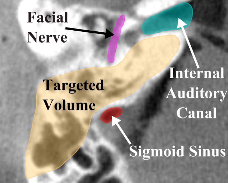
The bone in the mastoid region contains large air pockets (see Fig. 1). The number and size of these air pockets varies considerably between patients, and the density of bone varies spatially for each patient. In this paper, we propose the use of pre-operative imaging and force modeling to plan robot paths that account for these patient-specific bone property variations as well as the proximity of vital anatomy to the cutting burr. In comparison to treating the target region as a homogeneous volume of bone to be removed, this approach enables faster bone removal in areas with lower bone density and in areas far from critical structures. As the burr moves closer to the critical structures, cutting forces that would cause the tool to deflect in the direction of the structure and increase heat generation near temperature-sensitive anatomy are minimized by adjusting the robot velocity and orientation of the surgical drill.
Fig. 1.
A slice of a computed tomography (CT) scan of the temporal bone region. Both the target and vital anatomy that must be avoided are illustrated. Note also the porosity within the targeted bone volume to be removed, which lies in the mastoid region.
Several methods have been previously proposed for incorporating bone density variations into the planning and/or control of robotic bone drilling and milling. Sugita et al. employed a control scheme that accounted for the transitions between different bone types (cortical and cancellous) and air for reduction of procedure time and minimization of large force spikes in orthopedic bone milling [14]. Wang et al. used force-based control and knowledge of typical force levels in different areas of the vertebrae to avoid drill penetration beyond the targeted bone and damage to nerves [15]. In the field of otologic surgery, Williamson et al. used the correlation between drilling force and bone density to predict the pose of a robot-controlled drill based on density estimates from the pre-operative images and real-time force measurements [16]. Additionally, forces in otologic bone milling have been modeled in the development of a physics-based haptic simulator [17]. The voxelized model developed in [17] is used in the present work to adjust the cutting tool orientation and velocity along the trajectory for autonomous temporal bone milling such that the forces are decreased when the tool is in close proximity to vital anatomy and the tool is oriented for improved cutting efficiency.
II. Patient-Specific Motion Planning
A. Cartesian Path
The first step in the planning procedure is to generate a three-dimensional milling path through the bone that covers as much of the target volume as possible without crossing into untargeted regions (bone that need not be removed, or other anatomy). The output of this portion of the planning procedure is a list of N target points in the image coordinate frame. The only restriction on this path is that the current target point is reachable by the cutting burr and not beneath unmilled bone (i.e. target points 1 to i-1 must provide access to point i for the drill). This path can be calculated using a number of approaches, including a simple “lawnmower” approach (see e.g. [8], [14]), contour parallel tool paths [18], etc. Given this tool path, the remainder of this paper focuses on selecting the tool orientation and cutting velocity using patient-specific data.
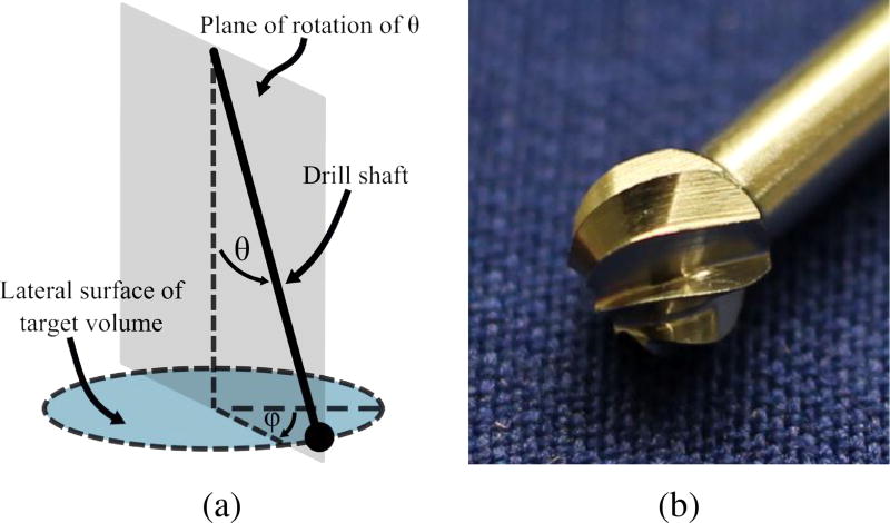
For each step along the 3D path, a range of permissible drill orientations can be calculated. This is done by examining the volume of bone previously removed in proximity to the point under consideration. Any shaft orientation that reaches the point, without colliding with unmilled bone, is considered a permissible orientation. Since the cutting burr is constantly rotating about its axis, only two orientation angles must be considered: ϕ and θ (see Fig. 2).
Fig. 2.
(a) Orientation angles of surgical drill with respect to bone surface. Since the drill rotates continuously, only two angles must be considered: θ and ϕ; (b) Photograph of fluted cutting burr for otologic surgery.
B. Efficient Cutting Angle
Surgical cutting burrs are typically spherical in shape with either a fluted or diamond-coated surface. Due to its shape, the side of the burr (i.e. near its equator) cuts more efficiently than the distal tip. In a study evaluating the forces during milling of the temporal bone, large force spikes (well beyond the mean forces for the parameters) were observed for spherical otologic burrs when primarily cutting with the distal tip [19]. In clinical practice, surgeons use the side of the burr whenever possible to increase cutting efficiency. As a simple metric for quantifying the amount of bone being cut with the side of the burr compared to the tip of the burr, an inertia-like quantity can be used:
| (1) |
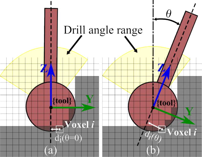
where i = 1…n represents all of the voxels that are at least partially covered by the cutting burr, ρi is the voxel density, Vi represents the partial volume of a given voxel, and di is the perpendicular distance from the shaft axis to the center of the voxel. The rightmost expression in (1) gives in terms of the radius of the burr, r, and the z-coordinate of the voxel, zi, in the tool coordinate frame shown in Fig. 3. Density is estimated based on the intensity of the voxel in the pre-operative CT scan. For different shaft orientations, the density and partial volume remain the same while di varies (see Fig. 3). I is maximized when the side of the burr is removing the largest quantity of bone possible. To account for varying quantity of bone along the path, I can be normalized based on the total amount of bone (calculated based on volume of voxel covered by the burr and intensity in image) that is to be removed at the given step:
| (2) |
which gives a value between 0 and 1. The normalization keeps the magnitude of this component of the orientation calculation in the same range for all points so the contribution of this component is consistent throughout the trajectory.
Fig. 3.
Cross-sectional illustration of the range of permissible angles at a given point along the path. Optimal shaft angle (θ) is determined based on the intensity and location of each voxel with respect to the drill shaft (di). Note that di also has a component in the x-direction in the 3D case and all of the voxels being cut are at the surface of the spherical burr. The figure shows how the distance between the shaft axis and the center of a single voxel changes with θ.
C. Reducing Forces Near Vital Anatomy
The orientation of the burr also influences the magnitude and direction of the cutting force between the burr and the bone. This is particularly true for spherical surgical burrs and non-homogeneous bone, where there can be considerable differences in cutting force direction with orientation change. When milling near vital anatomical structures in the temporal bone (e.g. the facial nerve), it is desirable to reduce the forces for two reasons. First, reduction of force in the direction of the structure decreases the likelihood of the burr deviating from the plan and colliding with the structure that needs to be preserved. Second, lower forces reduce the heat generation, decreasing the likelihood of thermal damage.
The model developed by Arbabtafti et al. [17] as part of their haptic simulator for bone machining using a spherical fluted cutting burr enables force estimation based on position of the burr and voxel intensity values. This model can be used to aid in robotic trajectory planning by predicting the forces based on the pre-operative images. From [17], the total force acting on each blade at any instant is given by:
| (3) |
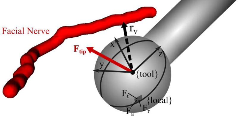
where Kt, Kr, and Ka represent the specific cutting energy for the material in the tangential, radial, and axial directions of the local coordinate frame, respectively, is the transformation between the local coordinate frame at the cutting position and the tool coordinate frame, and t is the chip thickness or depth of cut. Note that is unique for each position on the surface of the cutting burr (see Fig. 4). The cutting energies can be calibrated for the particular material by recording forces at various depths and tool orientations. The cutting tool also impacts the calibration since its geometry can influence how chips are removed, which can affect the forces on the tool.
Fig. 4.
Cutting burr in a position close to vital anatomy (facial nerve) showing the vector, rv, pointing from the burr center to the nearest point on the nerve. The tool coordinate frame and force vectors in the local coordinate frame for a single point along a blade are shown in the figure. Ft, Fr, and Fa represent the tangential, radial, and axial components of the force in the local coordinate frame, respectively.
Using (3), the differential forces acting along the blade are integrated over the entire surface of the blade engaged in cutting. This equation is expanded in discrete form in [17] for use in voxelized images and to account for all cutting blades. The forces along each discretized element of a blade are integrated along the z-direction at Nγ angular increments as the blade moves through a total angle of Ψ, which is the angle between two blades. This calculation is performed for each of the blades (1…Nβ) and averaged for each of the angular increments to obtain the total force on the burr:
| (4) |
where Nz represents the number of differential elements along the cutting blade in the z-direction and dz is the height of each element. See [17] for a more detailed derivation of the above equation.
The direction of the force, F = [Fx, Fy, Fz]T, can be compared to the vector between the cutting burr and the nearest point on the vital structure, rυ, to determine if the cutting force is pushing the burr towards the structure (see Fig. 4). The component of the force in the direction of the vital structure is:
| (5) |
where ûυ is the unit vector along rυ (Fυ is set to 0 for F · ûυ < 0). This information can be used to adjust the orientation of the drill such that the resultant force in the direction of the vital structure is minimized. Therefore, if there is a deflection of the robot, the likelihood of that deflection causing damage to the patient is reduced.
D. Orientation Selection
Given a range of shaft orientations for which the robot can safely reach the current target point, knowledge of what bone has been removed thus far in the path, and the CT scan of the patient, a desired shaft orientation can be calculated by minimizing a cost function that incorporates (2) and (5):
| (6) |
| (7) |
The coefficients α1 and α2 are varied based on the proximity to the nearest vital structure. When the burr is close to a structure that must be avoided, the first term of the cost function is the primary consideration. As the burr moves further away from the structure, the second term becomes the primary consideration. The scaling for a given point is based on the distance away from the vital structure at that point compared to the minimum allowable distance, rυ,min, as follows:
| (8) |
| (9) |
where κα determines how quickly the value of α1 drops off with distance away from the structure. If multiple vital structures are used in the planning algorithm, the closest one can be chosen for a given calculation. If multiple structures are in close proximity to the burr at any point in time, the higher priority structure can be used in the calculation. Alternatively, an additional term can be added to (6) to represent the force directed toward the second structure.
E. Incorporating Robot Deflection
Instead of simply using the direction of the force on the cutting burr, the deflection of the burr can be estimated given knowledge of robot stiffness. Assuming quasi-static loading and that the robot links are rigid relative to the joints, tip deflection can be approximated for a given force as:
| (10) |
where C(q) = Jχ−1JT is the compliance matrix of the robot. J is the robot Jacobian and χ = diag[k1, …, km] is a matrix of joint stiffnesses, where ki (i = 1…m) are the stiffness values for each of the m robot joints. Stiffness values representing “virtual joints” as described in [20] can also be included to account for off-axis joint compliance. Then, (5) and (6) become:
| (11) |
| (12) |
Δpυ is set to 0 for Δp · ûυ < 0.
F. Cutting Velocity
The velocity of the cutting burr along the trajectory is selected based on two factors: the amount of bone being removed and the orientation of the shaft at that point. When there is more bone (in terms of both volume and density), the robot should be programmed to cut slower. Since the total force is proportional to the mass of bone in contact with the burr and inversely proportional to the cutting velocity, an inverse relationship between mass and velocity is used ( ). The “mass” of bone can be calculated from image intensity and the partial volume of voxels within the burr as . To also account for the orientation-based cutting effectiveness and proximity to vital anatomy, the value determined from (6) or (12) is used. A low minimum cost function value means that there is an achievable orientation that provides good cutting performance. Thus, the velocity should be higher for lower values of C.
| (13) |
where kvel is a constant value that accounts for the magnitude of the intensity mapping such that the mean calculated velocity falls in the center of the allowed velocity range (υmin ≤ υcut ≤ υmax). The above equation yields high velocities at points when the amount of bone in contact with the burr is low or the bone to be cut is located at the side of the burr. Lower velocities are commanded when the burr is in contact with a large amount of dense bone, close to a vital anatomical structure, or it is not oriented well for efficient cutting. Due to the presence of air cells, the commanded υcut values can fluctuate rapidly as the burr moves in and out of air cells. A simple weighted, moving average filter is applied to the υcut data to ensure smooth motion and avoid very high accelerations at bone/air transition points.
G. Joint Trajectory Generation
The joint trajectory is generated from the target points (pburr), velocities (υcut), and desired orientation values (θdes, ϕdes). The desired drill orientation, as determined from minimizing the cost function, may change suddenly due to variable bone density and porosity. Thus, it is necessary to smooth these values to avoid rapid angle changes that may require joint velocities beyond the limits of the robot and reduce the ability of the surgeon to safely monitor the procedure. This smoothing can be applied directly to the desired angular values by using a low-pass filter. Alternatively, the orientation could be accounted for by considering only the Cartesian path positions as the task space and steering the orientation towards the desired value as a subtask in a redundancy resolution approach.
III. Experimental Methods
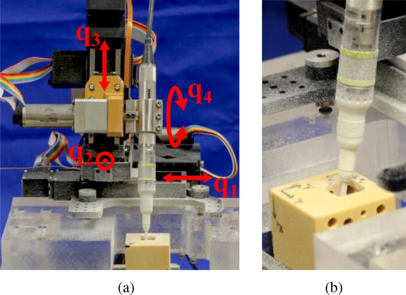
The algorithm described in this paper was tested on a four degree-of-freedom (DOF), bone-attached robot designed for mastoidectomy (see Fig. 5) [12]. Bone-attached robots can achieve higher positional accuracy since they do not require intra-operative tracking, which inherently introduces some level of registration error. However, they must be made small enough to mount on the patient without causing too much stress on the mounting points. Thus, these robots may not be as stiff as a larger robot and can therefore benefit from a planning algorithm that incorporates the minimization of deflection towards vital anatomy. Since the robot used in these experiments has three linear joints and one rotational joint, the drill shaft orientation is defined by this joint and the cost function is minimized over one variable, θ.
Fig. 5.
(a) Custom four DOF bone-attached robot for mastoidectomy mounted to test platform. The fourth joint (q4), which controls the drill orientation (θ) is determined by the optimization algorithm. (b) Close-up of surgical drill milling temporal bone phantom during an experiment.
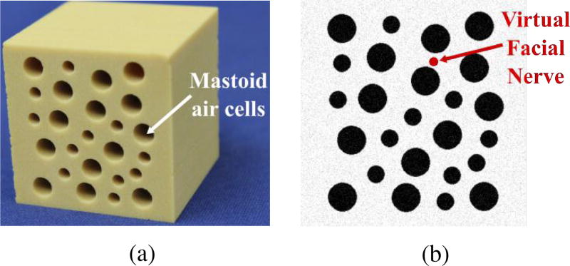
Experiments were performed using Sawbones (Pacific Research Laboratories, Vashon Island, WA USA) mechanical test blocks made from solid rigid polyurethane foam ( ). The blocks were custom-machined to add holes (3–5 mm in diameter) that mimic the air cells found in the mastoid region of the temporal bone. Fig. 6 shows a photograph of the test blocks and a slice of the image used for planning. To simplify the experimental protocol, the image was generated from a model of the custom-machined test blocks. To make the image-based planning more realistic, Gaussian noise with a standard deviation of 5% of the mean voxel intensity was added to the generated image. A virtual facial nerve was added to the image (see Fig. 6b) and its position was used in the trajectory planning algorithm. The block was placed in an experimental jig at a known location with respect to the robot. The same planning process would be used if the image was acquired using a CT scanner with the additional steps of localizing the structures and registering the anatomy to the robot.
Fig. 6.
(a) Photo of biomechanical test block used in experiments and (b) image slice of test block showing virtual facial nerve that was added to the image for testing of the planning algorithm.
A total of three experimental trials were performed. All trials were performed with the same Cartesian path at the same location in the phantom block, which enabled comparison between the different optimization approaches. The trajectory optimization step described in this paper is independent of the Cartesian path so any path could have been used in the experimental trials. For simplicity, the path used was a simple “lawnmower” type path in which the volume of bone was removed layer-by-layer. The outer path dimensions were 15 mm × 15 mm × 15 mm and the depth of each layer was 1.5 mm.
The first two trials were performed to evaluate the orientation selection component of the motion planning algorithm. The first trial, which serves as the control trial, used a constant angle (θ = 0°) and constant milling velocity ( ). The second trial was constrained to the same velocity but the orientation was varied along the path, with the value selected by minimizing (6). The optimization was performed using the fminbnd function in MATLAB 2015a (The MathWorks Inc., Natick, MA, USA). The drill inclination angle θ was bounded by both the limits of the robot and the constraints imposed by the unmilled bone at each point along the trajectory. Forces were recorded throughout both trials using a six axis force/torque sensor (Mini40, ATI Industrial Automation, Apex, NC, USA) positioned between the second and third joints of the robot. The force data was smoothed using a moving average filter and analyzed according to the position of the cutting burr at the time of the force reading. When the burr was within 2 mm of any point on the facial nerve, the measured force was projected along the unit vector between the burr and the closest point on the nerve (ûυ). The magnitude of forces towards the facial nerve was compared for the two trials. Additionally, the force values for all points along the trajectory were compared for the two trials.
A third milling trial was performed to include the velocity scaling component of the motion planning algorithm as well as the orientation selection. The same Cartesian path used in the two trials described above was planned in the phantom material. For this trial, the linear velocity, υcut, was regulated according to (13). The linear velocities were scaled such that the total procedure time was equal to the control trial (9 minutes, 26 seconds) and a fair comparison of forces could be made to prior trials. Again, (6) was used to select the drill orientation. The force data was recorded and compared to the first two trials.
IV. Results
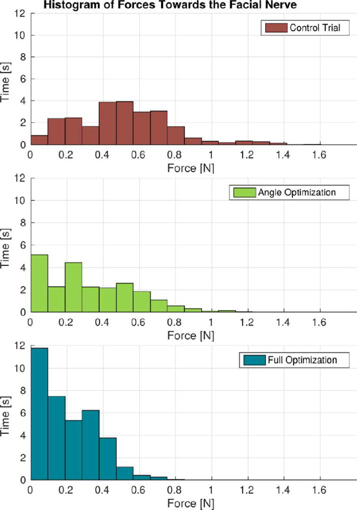
Fig. 7 illustrates the reduction of forces towards the facial nerve that was achieved through the implementation of the proposed approach. When the cutting burr was within 2 mm of the facial nerve, the control trial resulted in a mean force of 0.51 N, a 75th percentile force of 0.67 N, and a peak force of 1.60 N. The trial using the orientation optimization had mean, 75th percentile, and peak force values of 0.32 N, 0.50 N, and 1.16 N, respectively. Finally, the trial using the full (orientation and velocity) optimization had mean, 75th percentile, and peak force values of 0.19 N, 0.33 N, and 0.80 N, respectively. Compared with the control trial, the full optimization trial resulted in a 63% reduction in mean forces and a 50% reduction in peak forces toward the facial nerve.
Fig. 7.
Cutting forces towards the facial nerve when the burr was within 2 mm of the nerve. “Angle Optimization” refers to the trial in which only the regulation of the incidence angle was enabled and “Full Optimization” refers to the trial that used both angle and velocity regulation based on (6) and (13).
In addition to minimizing forces directed at the facial nerve, the proposed approach was found to produce an overall reduction of cutting forces throughout the milling process. This can be observed in the force magnitude plot (Fig. 8): the control trial resulted in a mean and peak force of 0.73 N and 3.24 N, whereas the trial that used variable incidence angle and milling velocity had mean a mean force of 0.66 N and a peak force of 1.69 N.
Fig. 8.
Force magnitude observed throughout the milling process. Here, “Full Optimization” refers to the trial that used both angle and velocity regulation. These plots show an overall reduction in mean and peak forces using the angle and velocity regulation. Note that the velocity was not constant throughout the full optimization trial so specific points along the path for the two trials do not occur at the same time. Thus, this plot provides a general comparison of the overall forces rather than a comparison at specific points along the path.
V. Discussion
The experimental results demonstrate that the proposed methodology has the potential to decrease cutting forces near vital anatomical structures and throughout the bone milling procedure. This is attributed to the incidence angle and velocity regulation scheme described by (6) and (13), which makes the robot mill more like a surgeon, i.e. varying the angle to control the cutting efficiency, moving slower when close to critical anatomy, and faster when in non-critical areas. This reduction of cutting forces is expected to bear two important clinical advantages. The first and most evident is that deflections of the robot towards vital anatomy (e.g. facial nerve, major blood vessels) will be smaller, thereby reducing the risk of accidental collisions when the burr is moving in close proximity to the structures. Second, lower cutting forces are expected to reduce the rate of thermal energy transferred to the surrounding bone, which could lead to heat-related trauma to the underlying vital structures. This latter implication is especially important in light of recent work that suggests high temperatures induced by bone drilling may cause thermal injury to the facial nerve [4], [21].
It is important to bear in mind that these results were obtained through experiments on synthetic bone, and that further experimentation is required to quantify the force reduction that can be achieved in a more clinically-relevant scenario. Temporal bone is denser than the material used in this study (up to vs. [22]). As a result, forces in actual bone will generally be higher than the ones reported here, which further emphasizes the importance of accounting for bone density and porosity variations. Future research to translate the methodology to actual temporal bone will be directed at evaluating how this method scales up to scenarios that involve higher forces and potentially higher variability in bone composition. This will require exploration of strategies to regulate the coefficients of the cost function (6) that govern the trade off between cutting efficiency and force minimization near the vital structures. It will also be necessary to precisely quantify the performance improvements achievable with respect to CNC-like temporal bone milling.
In addition to reducing cutting forces, the velocity regulation method presented here has the potential to enable time savings during robotic mastoidectomy. In some mastoidectomy procedures (e.g. the translabyrinthine approach for acoustic neuroma tumor removal), the surgeon spends several hours manually removing bone before beginning the primary surgical task of tumor resection. Thus, speed improvements during the milling component of the procedure would reduce overall operation time. This procedure time improvement is accomplished by increasing the velocity when the cutting burr goes through either non-critical areas or porous regions of the bone. The time decrease is partially balanced by the slow velocities used when milling close to critical structures. Note that in a clinical scenario this would save more time than was saved in these experiments because a larger percentage of time would be spent milling far from critical structures (in these experiments we milled a smaller pocket than would typically be required in mastoidectomy - 15 mm × 15 mm × 15 mm vs. approximately 30 mm × 40 mm × 40 mm).
VI. Conclusion
This paper presented a novel method for robotic bone milling that uses image-based bone density estimates along with the location of vital anatomy to generate a safe and efficient cutting plan. The method regulates the burr incidence angle to control the cutting forces that occur at the burr-bone interface. The objectives are to improve the safety and efficiency of the milling procedure by avoiding large forces that could deflect the robot towards towards vital anatomy (e.g. facial nerve), thus reducing the risk of accidental collisions, as well as enabling faster milling in areas of low density bone. The tool orientation and cutting velocity are selected based on the local density of bone and the proximity to vital anatomic structures.
The proposed method was implemented using a 4-DOF bone-attached robot for mastoidectomy. Milling experiments were performed on custom temporal bone phantoms and preliminary experimental results revealed a reduction of mean and peak forces compared to CNC-like bone milling. Furthermore, the approach enables faster milling of porous bone located in non-critical areas, potentially reducing overall procedure time. Future research will focus on further experimental validation of the approach. As a next step, experiments using cadaveric temporal bones will be conducted to determine whether the advantages seen in this preliminary evaluation translate as expected to biological tissues.
Acknowledgments
This work was supported by award number R01 DC012593 from the National Institutes of Health. The content is solely the responsibility of the authors and does not necessarily represent the official views of the National Institutes of Health.
Contributor Information
Neal P. Dillon, Department of Mechanical Engineering, Vanderbilt University, Nashville, TN USA..
Loris Fichera, Department of Mechanical Engineering, Vanderbilt University, Nashville, TN USA..
Patrick S. Wellborn, Department of Mechanical Engineering, Vanderbilt University, Nashville, TN USA.
Robert F. Labadie, Department of Otolaryngology, Vanderbilt University Medical Center, Nashville, TN, USA.
Robert J. Webster, III, Department of Mechanical Engineering, Vanderbilt University, Nashville, TN USA..
References
- 1.Paul HA, Bargar WL, Mittlestadt B, Musits B, Taylor RH, Kazanzides P, Zuhars J, Williamson B, Hanson W. Development of a surgical robot for cementless total hip arthroplasty. Clinical Orthopaedics and Related Research. 1992;285:57–66. [PubMed] [Google Scholar]
- 2.Ho S, Hibberd R, Davies B. Robot assisted knee surgery. IEEE Engineering in Medicine and Biology Magazine. 1995;14(3):292–300. [Google Scholar]
- 3.Labadie RF, Mitchell J, Balachandran R, Fitzpatrick JM. Customized, rapid-production microstereotactic table for surgical targeting: description of concept and in vitro validation. International Journal of Computer Assisted Radiology and Surgery. 2009;4(3):273–280. doi: 10.1007/s11548-009-0292-3. [DOI] [PMC free article] [PubMed] [Google Scholar]
- 4.Labadie RF, Balachandran R, Noble JH, Blachon GS, Mitchell JE, Reda FA, Dawant BM, Fitzpatrick JM. Minimally invasive image-guided cochlear implantation surgery: First report of clinical implementation. The Laryngoscope. 2014;124(8):1915–1922. doi: 10.1002/lary.24520. [DOI] [PMC free article] [PubMed] [Google Scholar]
- 5.Kratchman LB, Blachon GS, Withrow TJ, Balachandran R, Labadie RF, Webster RJ. Design of a bone-attached parallel robot for percutaneous cochlear implantation. IEEE Transactions on Biomedical Engineering. 2011;58(10):2904–10. doi: 10.1109/TBME.2011.2162512. [DOI] [PMC free article] [PubMed] [Google Scholar]
- 6.Bell B, Stieger C, Gerber N, Arnold A, Nauer C, Hamacher V, Kompis M, Nolte L, Caversaccio M, Weber S. A self-developed and constructed robot for minimally invasive cochlear implantation. Acta Oto-Laryngologica. 2012;132(4):355–360. doi: 10.3109/00016489.2011.642813. [DOI] [PubMed] [Google Scholar]
- 7.Kobler J-P, Kotlarski J, Öltjen J, Baron S, Ortmaier T. Design and analysis of a head-mounted parallel kinematic device for skull surgery. International Journal of Computer Assisted Radiology and Surgery. 2012;7(1):137–149. doi: 10.1007/s11548-011-0619-8. [DOI] [PubMed] [Google Scholar]
- 8.Federspil PA, Geisthoff UW, Henrich D, Plinkert PK. Development of the first force-controlled robot for otoneurosurgery. The Laryngoscope. 2003 Mar.113(3):465–71. doi: 10.1097/00005537-200303000-00014. [DOI] [PubMed] [Google Scholar]
- 9.Xia T, Baird C, Jallo G, Hayes K, Nakajima N, Hata N, Kazanzides P. An integrated system for planning, navigation and robotic assistance for skull base surgery. The International Journal of Medical Robotics and Computer Assisted Surgery. 2008;4(4):321–330. doi: 10.1002/rcs.213. [DOI] [PMC free article] [PubMed] [Google Scholar]
- 10.Danilchenko A, Balachandran R, Toennis JL, Baron S, Munkse B, Fitzpatrick JM, Withrow TJ, Webster RJ, III, Labadie RF. Robotic Mastoidectomy. Otology & Neurotology. 2010;(32):11–16. doi: 10.1097/MAO.0b013e3181fcee9e. [DOI] [PMC free article] [PubMed] [Google Scholar]
- 11.Lim H, Han J-M, Hong J, Yi B-J, Lee SH, Jeong JH, Matsumoto N, Oka M, Komune S, Hashizume M. Image-guided robotic mastoidectomy using human-robot collaboration control. 2011 International Conference on Mechatronics and Automation; IEEE; 2011. pp. 549–554. [Google Scholar]
- 12.Dillon NP, Balachandran R, Fitzpatrick JM, Siebold MA, Labadie RF, Wanna GB, Withrow TJ, Webster RJ. A compact, bone-attached robot for mastoidectomy. Journal of Medical Devices. 2015;9(3):031 003–1–7. doi: 10.1115/1.4030083. [DOI] [PMC free article] [PubMed] [Google Scholar]
- 13.French LC, Dietrich MS, Labadie RF. An estimate of the number of mastoidectomy procedures performed annually in the united states. Ear, Nose & Throat Journal. 2008;87(5):267. [PubMed] [Google Scholar]
- 14.Sugita N, Nakano T, Nakajima Y, Fujiwara K, Abe N, Ozaki T, Suzuki M, Mitsuishi M. Dynamic controlled milling process for bone machining. Journal of Materials Processing Technology. 2009;209(17):5777–5784. [Google Scholar]
- 15.Wang T, Luan S, Hu L, Liu Z, Li W, Jiang L. Force-based control of a compact spinal milling robot. The International Journal of Medical Robotics and Computer Assisted Surgery. 2010;6(2):178–185. doi: 10.1002/rcs.304. [DOI] [PubMed] [Google Scholar]
- 16.Williamson TM, Bell BJ, Gerber N, Salas L, Zysset P, Caversaccio M, Weber S. Estimation of tool pose based on force–density correlation during robotic drilling. IEEE Transactions on Biomedical Engineering. 2013;60(4):969–976. doi: 10.1109/TBME.2012.2235439. [DOI] [PubMed] [Google Scholar]
- 17.Arbabtafti M, Moghaddam M, Nahvi A, Mahvash M, Richardson B, Shirinzadeh B. Physics-based haptic simulation of bone machining. IEEE Transactions on Haptics. 2011;4(1):39–50. doi: 10.1109/TOH.2010.5. [DOI] [PubMed] [Google Scholar]
- 18.Dhanik S, Xirouchakis P. Contour parallel milling tool path generation for arbitrary pocket shape using a fast marching method. The International Journal of Advanced Manufacturing Technology. 2010;50(9–12):1101–1111. [Google Scholar]
- 19.Dillon NP, Kratchman LB, Dietrich MS, Labadie RF, Webster RJ, III, Withrow TJ. An experimental evaluation of the force requirements for robotic mastoidectomy. Otology & Neurotology. 2013 doi: 10.1097/MAO.0b013e318291c76b. [DOI] [PMC free article] [PubMed] [Google Scholar]
- 20.Abele E, Rothenbücher S, Weigold M. Cartesian compliance model for industrial robots using virtual joints. Production Engineering. 2008;2(3):339–343. [Google Scholar]
- 21.Feldmann A, Anso J, Bell B, Williamson T, Gavaghan K, Gerber N, Rohrbach H, Weber S, Zysset P. Temperature prediction model for bone drilling based on density distribution and in vivo experiments for minimally invasive robotic cochlear implantation. Annals of Biomedical Engineering. 2016;44(5):1576–1586. doi: 10.1007/s10439-015-1450-0. [DOI] [PubMed] [Google Scholar]
- 22.Kobler J-P, Prielozny L, Lexow G, Rau TS, Majdani O, Ortmaier T. Mechanical characterization of bone anchors used with a bone-attached, parallel robot for skull surgery. Medical Engineering & Physics. 2015;37(5):460–468. doi: 10.1016/j.medengphy.2015.02.012. [DOI] [PubMed] [Google Scholar]


