

Abstract
This paper presents a wirelessly powered, fully integrated system-on-a-chip (SoC) supporting 160-channel stimulation, 16-channel recording, and 48-channel bio-impedance characterization to enable partial motor function recovery through epidural spinal cord electrical stimulation. A wireless transceiver is designed to support quasi full-duplex data telemetry at a data rate of 2 Mb/s. Furthermore, a unique in situ bio-impedance characterization scheme based on time-domain analysis is implemented to derive the Randles cell electrode model of the electrode-electrolyte interface. The SoC supports concurrent stimulation and recording while the high-density stimulator array meets an output compliance voltage of up to ±10 V with versatile stimulus programmability. The SoC consumes 18 mW and occupies a chip area of 5.7 mm × 4.4 mm using 0.18 μm high-voltage CMOS process. In our in vivo rodent experiment, the SoC is used to perform wireless recording of EMG responses while stimulation is applied to enable the standing and stepping of a paralyzed rat. To facilitate the system integration, a novel thin film polymer packaging technique is developed to provide a heterogeneous integration of the SoC, coils, discrete components, and high-density flexible electrode array, resulting in a miniaturized prototype implant with a weight and form factor of 0.7 g and 0.5 cm3, respectively.
Index Terms: Spinal cord injury, paralysis, epidural, EMG, neuroprosthetics, implant, stimulation, recording, power and data telemetry, neural engineering, neural interface, bioelectronics, electroceuticals, system-on-a-chip (SoC)
I. Introduction
The estimated number of spinal cord injury (SCI) patients in the U.S. in 2016 is 282,000 with an annual incidence of approximately 54 cases per million populations and an estimated lifetime cost of > $1.1M per patient. SCI is defined as damage to the spinal cord that leads to permanent or temporary neurologic deficit [1]. Patients with SCI often lose their sensation, mobility, or even autonomic function as the control from the brain to the rest of the body is completely or partially lost at the level of the spinal cord lesion, bringing a tremendous socioeconomic impact on the U.S. healthcare system. However, although SCI interrupts the cerebro-spinal pathway, key planning, coordination, and effector centers above and below the injured spinal segment still remain intact [2–5]. Brain machine interface is a viable approach for restoring motor function through cortical stimulation. A closed-loop neural microsystem has been presented in [6] to reconstruct the communication between the motor and somatosensory cortical areas. In addition, spinal cord electrical neuromodulation has been shown to activate the complex spinal cord circuitries, providing the opportunity for partial motor function recovery after spinal cord injury [4, 7–10].
However, the development of implantable systems using epidural stimulation for restoring the motor function of the paralyzed is still in its infancy. Recent human clinical experiments still rely on commercial spinal cord electrode arrays and stimulators specifically designed for pain suppression [8, 10] with limited stimulation capabilities and a bulky form factor. Though efforts have been devoted to developing research tools/devices, many might not be appropriate for the application of motor function recovery. For example, the devices presented in [7, 11] have been demonstrated in spinal cord transected rodent experiments to enable stepping and standing through electrical stimulation, but they rely on discrete wires for the communication with the implant, imposing the risk of infection on the subject and increasing the complexity of the surgical procedure. A wireless device adapted from the deep brain stimulator has also been used to perform intra-spinal stimulation in the rodent model [12, 13]. However, it is not implantable and does not support real time physiological recording or recording of kinetics, both of which are widely used by researchers/clinicians to evaluate the effectiveness and optimize the protocol of the spinal cord stimulation [3, 4, 7, 14, 15].
Unlike some published cortical implants that stimulate with a pre-loaded stimulation pattern only when sensing abnormal neural activities [16, 17], the implant for motor function recovery must be capable of simultaneously adjusting its stimulation patterns (e.g., stimulation intensity, location, pulse width, polarity, and frequency) at run time in response to the subject’s varying physiological states recorded during ongoing stimulation. Recently, a brain-spine interface has been developed to alleviate gait deficits in primates with incomplete spinal cord injury [18]. This interface comprises of three individual components enabling wireless cortical recording, wireless EMG recording, and wireless stimulation. Yet initiating each stimulation requires stimulation trigger commands to be sent to the implanted stimulator. This implies that a pre-loaded parameter is used in its study and the only parameter capable of real-time update is the stimulation frequency, which is controlled by the onset frequency of the trigger command.
In addition, a high-density stimulator is preferred to support the stimulation with high spatial resolution. This would facilitate the focused stimulation only on the relevant area of the spinal cord, thus optimizing the motor outcome [7]. The size of the implant must also be miniaturized to reduce surgical invasiveness. The state-of-the-art neuromodulation implant presents a 4-channel stimulator with wireless data and power links for small animal experiments. Although it weighs 6 g and has a volume of 3 cm3 [19], it is still preferable for the implant to have a size comparable to its bioelectronics, thus minimizing its surgical invasiveness. Furthermore, the epidural electrode should be soft and flexible because the spinal cord is one of the most demanding environments in the central nervous system [20]. The implant should also be capable of characterizing the electrode impedance in order to determine the safe stimulation boundary, ensuring that the electrode overpotential is within the water window [21]. Thus, an implant which can fulfill the above function requirements is highly needed.
Fig. 1 shows the conceptual system illustration for the proposed spinal implant for motor function recovery using a rodent model. The implant and coils are implanted subcutaneously, where the EMG wire electrodes from the implant are sutured to the leg muscles for recording while the electrode array is inserted into the epidural space for electrical stimulation. The rat carries a rendezvous device (RD) that wirelessly powers the implant, and serves as a link between the implant and a remote control device (e.g. smartphone). This paper focuses on the design of the SoC implemented in 0.18 μm 32 V 1P6M high-voltage (HV) CMOS process, as well as the development of a miniaturized implant. The SoC supports 160-channel current-mode stimulation, 16-channel physiological signal recording, and 48-channel bio-impedance characterization with 2 Mb/s quasi full-duplex data telemetry at 18 mW. The miniaturized implant has a weight and form factor of 0.7 g and 0.5 cm3, respectively, including the coils, six 0201 passive components, the SoC, and the high-density flexible polyimide based platinum electrode array.
Fig. 1.

Conceptual illustration of the implantable system for motor function recovery using a rat model. User GUI can be a tablet or smart phone that communicates with the RD carried by the rat. The RD configures and powers the implant through an inductive link.
The remainder of this paper is organized as follows. Section II describes the mechanism of epidural spinal cord stimulation for motor function recovery. Section III presents the system design consideration. Section IV gives the system overview while Section V describes the circuit and implant implementation. Finally, measurement results are given in Section VI and Section VII concludes the paper.
II. The Nature of the Responses Produced by Spinal Cord Epidural Stimulation
The complex neural networks residing in the lumbosacral spinal segment can function to produce alternating motor patterns, which can be further alternated through the sensory feedback [5, 7]. For example, one’s walking gait can be alternated unconsciously when stepping from a flat surface to a bumpy one. Fig. 2 illustrates the possible mechanism for epidural stimulation to recover motor function. The stimulus delivered from the epidural electrode activates the dorsal spinal ganglions. Some combination of epidural stimulation and afferent inputs (e.g., Ia, Ib, and II sensory feedback) derived from the moving limbs appear to facilitate the EMG burst (Fig. 2). It is thus speculated that the origin of these evoked EMG responses is due to the activation of a complex inter-neuronal network (i.e., FRA spinal cord ventral horn interneuron) modulated electrically and through proprioception. The inter-neuronal networks then possibly drive and coordinate the motor neuron to initiate motor function, such as stepping and weight-bearing standing [22].
Fig. 2.

Schematic representation of the epidural electrode on the spinal cord, creation of the electric field for stimulation, and multiple EMG responses generated in muscles based on latency post stimulus.
The responses of EMG also vary with different stimulation parameters (i.e. frequency and intensity) and sites where the stimuli are applied. EMG responses include early response (ER), middle response (MR), and late response (LR). The characteristics of the ER are consistent with the direct activation of motor fibers or motoneurons with a latency of 1–3 ms and its amplitude increases with stimulation intensity. The short latency ER may include just the neuromuscular synaptic delay and the conduction time of the stimulus to the muscle within the spinal cord. The MR reflects the delay of one or more synaptic delays with a latency of 4–8 ms with an inhibition at higher intensities and frequency of stimulation. The LR has the longest latency of the three responses (7–11 ms) and represents a polysynaptic event. The latency difference between the ER and LR is about 6 to 8 ms and may correspond to as many as three synaptic delays. With increased stimulus intensity the amplitude of the LR initially increases and then is completely inhibited at high stimulus intensities [7].
III. System Design Consideration
The SoC for motor function recovery shares many design principles with other implantable devices, such as flexible stimulation waveforms at each individual channel, high-compliance voltage for stimulator, wireless power and data link, which have been discussed in our previous work [23] and others [16, 17, 24–26]. Based on our prior study in [7], the stimulation should cover frequencies between 1–100 Hz while the optimal number of required stimulation channels is still under investigation. On the other hand, the number of recording channels should be > 8 to cover EMG recording from both extensor and flexor muscles (e.g., soleus (SoL), tibialis anterior (TA), myasthenia gravis (MG), and vastus lateralis (VL) muscles) in hind limbs for the purposes of evaluating the performance of restoring the motor functions. The recording front-end circuits need to detect EMG signal whose amplitude ranges from tens of μV to several mV and bandwidth ranging from ~10 Hz to ~2 kHz [27]. This can be translated into a wireless data rate requirement of > 320kb/s (i.e., 8 channels × 10b digitization × 4 kHz sampling rate). A higher date rate would still be preferred to expand the potential application of the SoC and shorten the latency when implementing a closed-loop system. In addition to the aforementioned requirements, design requirements for the spinal implant should also include:
A. Wireless Duplex Data Link
The implant for motor function recovery should be capable of varying its stimulation sites and parameters based on the recorded physiological signals [15]. As the optimal stimulation parameters and sites vary among different subjects and the stimulation strategy is still under investigation using both animal and human models [7, 8, 14], we decide to transmit the recorded physiological signal to the RD and the GUI (e.g., tablet or smartphone), allowing for further signal processing and leaving the flexibility to improve the computing algorithm. Hence, a duplex wireless link is necessary so that the forward link to configure the stimulation parameters can be simultaneously transmitted while the reverse data link is used for wireless recording.
Furthermore, the design of the transceiver should be simplified to reduce its power consumption and the number of discrete components used by the implant. A strategy presented in [28] is to separate the transmit and receive signal frequency to realize a duplex data link using a single antenna. Transmitter-to-receiver signal isolation is improved by shaping the power spectrum of the transmitted signal and by filtering the feed-through signal from the transmitter with a narrow band low-noise amplifier at the receiver. Nonetheless, in adapting this method for a transceiver operated at a low frequency (i.e., MHz), a fully integrated solution is challenging and usually requires extra off-chip components. To overcome the above challenges, we develop a simple, yet effective method by adopting two different modulation schemes for transmit and receive signals, respectively. This prevents the occurrence of incorrect decoding even when the transmit signal couples to the receiver. Implementation of the data link is given in Section V.
B. Impedance Characterization
Measuring the bio-impedance can be used to evaluate the reliability of an electrode and to determine the safe stimulation boundary (i.e., stimulation pulse-width and intensity). However, characterizing the bio-impedance across a broad spectrum requires sophisticated equipment and is time-consuming, but doing so at a fixed frequency provides limited information. A time-domain analysis method developed in our laboratory that efficiently utilizes hardware in the implant to characterize the bio-impedance [21] is thus implemented in the SoC. As shown in Fig. 3, by adopting a simple three-element Randles cell electrode model consisting of a charge transfer resistance RCT, a double layer capacitance Cdl, and a tissue-solution resistance RS, impedance characterization can be performed by injecting a low-intensity, short-period biphasic current stimulus with a pre-defined inter-pulse delay to the electrode and by measuring the resulting electrode overpotential at three specific points (i.e., V0, V1, and V2 in Fig. 3). RS can be estimated by measuring V0 immediately after the stimulus is fired, as it represents the transient voltage increase when the instantaneous current is flowing through RS. On the other hand, utilizing a small and short stimulus can minimize the fraction of Faradic current, allowing the estimation of Cdl by simply measuring the resulting electrode voltage at the end of the leading pulse (i.e., V1 in Fig. 3). Subsequently, during the inter-pulse delay tinterpulse, the charge stored in Cdl is passively discharged. Insertion of the inter-pulse delay then provides a well-specified discharge time and a known timing to sample the electrode potential V2. Once V2 is derived, RCT can be estimated. Finally, a compensating pulse is applied for charge balance. The derivation of the electrode model does not require sophisticated computation and can be integrated into implants capable of performing simultaneous recording and stimulation. To further minimize the residual charge accumulated on the stimulation electrode, we also implement a passive charge balance scheme by shorting the electrode to ground after stimulation.
Fig. 3.

In situ impedance characterization (a) Randles cell electrode model (b) Electrode overpotential resulted from a biphasic stimulus with small intensity and inter-pulse delay.
C. Flexible Electrode Array and Miniaturization Package
The electrode for spinal cord stimulation is required to provide mechanical flexibility and durability because it must withstand the constant motion of the spine. In addition, there is a need for a high-density electrode array, as this would provide high spatial selectivity to enable focused delivery of the stimulus to specific spinal areas for optimizing the motor output [7]. In order to fulfill the above requirements, we develop a fabrication process for flexible multi-electrode array to support versatile stimulation [29]. Low stress thin film polyimide is used as the electrode substrate for its high mechanical strength, low moisture uptake rate, and low dielectric constant compared to other polymers. A platinum/titanium metal layer is selected for the electrode material, as it possesses high stability and biocompatibility. A roughening process is further conducted to increase the effective surface area of the electrode, increasing the safe delivered electric charge [29]. Critically, it has always been a challenge to miniaturize the implant that is composed of electronics, passive components (off-the-shelf resistors and capacitors), coils, and an electrode array. A widely adopted approach uses a printed circuit board (PCB) to connect the above-mentioned components, but this is less practical for implants with high input/output counts under the strict requirement of a small form factor. Adapted from our electrode fabrication process, we advance a heterogeneous integration method to miniaturize the size of the implant using a thin film polymer package.
IV. System Overview
The system diagram of the implant is shown in Fig. 4. A GUI communicates with the RD through WIFI while the RD and the implant are inductively coupled. The core of the implant is a mixed-signal, multi-voltage SoC performing 160-channel current stimulation with high compliance voltage, 16-channel recording, and 48-channel bio-impedance characterization with fully integrated power/data telemetry. Improved upon [30], a quad-voltage power converter generates four different voltages to power the implant, with added capability of adjusting the supply voltages for the stimulators (± 6/8/10/12 V) to accommodate various bio-impedances. A quasi full-duplex data transceiver links the SoC and the rendezvous device at 2 Mb/s. The NEural Command Signal Interface System (NECSIS) controller determines the implant operation based on the received commands (CMDs). Stimulation of 160 channels is achieved by 40 stimulation current drivers, each with a 1:4 Demux [23]. For impedance measurement, 12 out of 40 Demux inputs are selectively connected to the 16:1 MUX made of HV transistors, allowing 48 electrodes to be characterized. HV MUX is also connected to the power converter outputs and two of the MUX inputs are reserved for inertial and temperature sensors for future integration. The clock generator uses the 2 MHz power carrier to produce the 2 MHz clock and an on-chip conventional 3-stage ring oscillator is designed to generate the 16 MHz clock. Similar to [23], this SoC supports chip clustering using a 2-bit ID control. By sharing the same coils, a four-SoC cluster can be integrated into one implant to provide 640-channel stimulation, 64-channel recording, as well as 192-channel impedance characterization.
Fig. 4.

System diagram of the implant and the proposed SoC for motor function recovery.
V. Circuit and Implant Design
A. Quasi Full-Duplex Data Link
The block diagram of the quasi full-duplex data transceiver is shown in Fig. 5(a). Unlike other inductive-powered implants whose reverse data link is realized by using its power coil optimized for power transfer efficiency (i.e. high quality factor), a low-Q data coil is used for both the forward and reverse links to achieve a high data rate. The transceiver incorporates a differential phase-shift keying (DPSK) receiver for its good immunity to interference and a LSK transmitter for low-power consumption. The DPSK signal contains command data at a 2 Mb/s data rate modulated by a 20 MHz carrier. This signal is sent by the external DPSK transmitter to the DPSK receiver through an inductive link. In the receiver, a 2nd order high pass filter first attenuates out-of-band noise. Next, a subsampling technique is employed, where the sampling frequency is determined by the carrier frequency and targeted data rate [31]. The incoming DPSK command signal is then sampled at 16 MHz to finally demodulate the raw data [23]. In the reverse link, the signal to be transmitted through the LSK transmitter is combined through the 4:1 multiplexer. The single wire bit stream is then boosted from 1.8 V to ±1.8 V in order to modulate the load of the data coil through the 5 V NMOS LSK switch. As the reverse link adopts LSK modulation, the DPSK receiver is less likely to pick up the transmitted LSK signal. However, to avoid possible incorrect data decoding, a second protection scheme is further implemented in the digital controller of the SoC (see sub-section D).
Fig. 5.
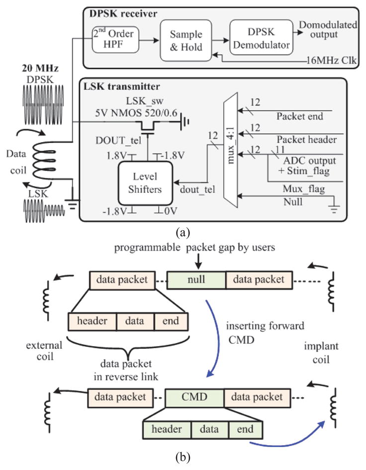
(a). Schematic of the quasi full-duplex transceiver. (b) Communication protocol for the quasi full-duplex data link.
In order to support quasi full-duplex link, we designate a communication protocol based on time multiplexing (Fig. 5(b)). Each data packet contains a user defined header, digitized physiological data, and an end marker. The LSK transmitter in the SoC sends the recorded data in packets separated by time gaps with a programmable length. Importantly, once the RD recognizes the end marker and there is a need to re-configure the implant, a new CMD that has a similar data structure to the recording data packet can be sent to the SoC within this time gap, allowing the use of the same coil for both transmit and receive signals.
B. Physiological Signal Recording Front-End
The schematic of the recording front-end is shown in Fig. 6. The first stage is an AC-coupled amplifier adapted from our prior work [32] with a targeted gain of 40 dB. The second stage is a programmable bandpass filter composed of a R-C high-pass filter and a gm-C low pass filter [33]. The high-pass and low-pass cutoff frequencies of the subsequent bandpass filter are adjustable by tuning the resistance of the pseudo-resistor via Vtune and by altering the transconductance of the gm-C filter with a 1-bit digital control. Vtune is pre-set to 1.8 V through an on-chip resistor and can be adjusted by connecting an additional external resistor to the SoC pin. The third stage is a programmable gain amplifier with 2-bit control to tune the ratio of the input and feedback resistors. Subsequently, a 16:1 multiplexer connects 16-channel outputs to the back-end ADC for signal digitization.
Fig. 6.

Schematic of the physiological signal recording front-end and the block diagram of the pipeline ADC.
The ADC is designed with a pipelined topology, resolving the rail-to-rail input into a 10-bit digital output. The input rail-to-rail unity gain amplifier buffers the recorded single-ended signal (Fig. 6). The first stage of the ADC converts the incoming single-ended signal to pseudo differential outputs. All ADC stages are also designed as differential to improve SNR of the full chain and increase tolerance to common-mode errors. The remaining architecture follows a conventional pipelined ADC topology with a switched-capacitor gain amplifier at the core of each stage. An error correction circuit is added to allow corrections for the comparator offset and other non-idealities. This is accomplished by designing each ADC stage in the pipeline to have a 1.5-bit topology, where the 0.5 bit overlaps with the next stage’s output to allow for digital error correction [34].
C. Bio-Impedance Characterization
The circuit implementation for the bio-impedance characterization is illustrated in Fig. 7. Of the 40 Demux inputs, 12 are connected to a 16:1 multiplexer made of high voltage transistors for impedance characterization (Fig. 3). Voltage clamp diodes are cascaded at the 16:1 MUX output to protect the 2:1 multiplexer made of low-voltage transistors. The measured electrode overpotential is digitized by the 10-bit pipeline ADC that is shared with the recording front-end. The purpose of the Stim_flag bit is to denote the onset of the stimulation. The serializer then incorporates the Stim_flag bit into the serialized ADC output. Based on the previously described method, the bio-impedance characterization module then estimates the Randles cell electrode model with the known stimulation parameters and measured electrode overpotential. Using the characterization of electrode #2 (CH#2) as an example, when Stim_flag is triggered to “1” to indicate the onset of a stimulus, the measured electrode overpotential following Stim_flag is indicated as V0. As the stimulation parameters, such as intensity (I0), pulse width (tanode and tcathod), and interpulse delay (tinterpulse), are stored in the SoC using a data structure developed in [35], V1 and V2 can be found accordingly after the Stim_flag bit is raised to high. It is important to note that in using the proposed method, only three values of the electrode voltage are required to estimate the impedance. Moreover, instead of designing complex or specific circuits for impedance measurement, we take advantage of the intrinsic functions supported by the SoC (i.e. recording and stimulation), that allow the derivation of the equivalent circuits model of the electrode-electrolyte interface.
Fig. 7.

The schematics for bio-impedance characterization.
D. NECSIS Controller
The NEural Command Signal Interface System (NECSIS) controller serves as the central control unit for the SoC. It consists of a global stimulation controller and a recording controller (Fig. 8). The incoming DPSK output contains a corresponding header and command, wrapped in a packet. During the operation of the NECSIS controller, the stimulation and recording controllers both listen to the incoming DPSK output, but only react to the command that can pass its own header check. In the case of a header mismatch, the data will be simply discarded.
Fig. 8.

Block diagram of the NECSIS controller.
When the implant is intended for stimulation, the DPSK output containing header #1 will be recognized and decoded by the global stimulation controller and will be distributed to every local digital controller for stimulation control. The global and local stimulation controllers have the architecture of a highly programmable digital controller used for neural prosthesis [23, 36] due to its fine-grained and independent control over multiple stimulators simultaneously. This allows the stimulation parameters of intensity, stimulus polarity, pulse width, and interpulse delay to be independently programmed in each channel [35, 37].
When the implant is intended for recording or performing simultaneous recording and stimulation, the recording controller takes over the control of the SoC once it recognizes the DPSK output signal containing header #2. It then configures the following functional blocks: 1) the recording front-end to determine the gain, bandwidth, channels of interests, and ADC sampling frequency, 2) the transceiver to determine the data rate, the size of packet to be transmitted, and the length of the packet gap, and 3) the stimulator to configure the stimulation parameters for each channel. Moreover, in order to perform simultaneous recording and stimulation, the recording controller sets the 2:1 multiplexer so the global stimulation controller only takes commands from the recording controller. The stored stimulation parameters are relayed to the global stimulation controller to enable concurrent stimulation and recording (Fig. 8).
E. Flexible Electrode Array and Thin Film Package
The illustration of the electrode array and the heterogeneous thin film polymer packaging is shown in Fig. 9 [38]. A flexible polymer substrate and electrode array are designed and fabricated through a process similar to [29]. The bond pads, electrodes, and interconnects on the flexible substrate are fabricated using e-Beam evaporation deposition as platinum and titanium layers. All necessary electrical connections to enable the function of the SoC are made through the patterned metal trace on the polymer substrate, serving as a flexible circuit board. The opening of the bump pad is specifically designed for the integration of the SoC and the polymer substrate. Gold ball bumps are placed to bond the top-metal I/O pads of the CMOS SoC. Coils and external capacitors are connected to the contact of the substrate pads using silver-filled conductive epoxy (EPO-TEK H20E, Epoxy Technology Inc., MA). The final implant is then hermetically sealed by encapsulation with non-conductive epoxy (3M DP100 Plus Clear, 3M Corp., MN).
Fig. 9.

Illustration of the electrode array and the packaging.
VI. Experimental Results and Discussion
The proposed SoC is designed and fabricated in 0.18 μm HV CMOS with an area of 5.7 × 4.4 mm2, as shown in Fig. 10. This SoC is packaged in a QFP 208-pin package for both bench-top and in vivo testing. The SoC is then integrated with custom-made coils and passive components using the proposed thin film polymer package to evaluate and validate our assembly and fabrication process, respectively. Three experiments are conducted: 1) a bench-top test, 2) an in vivo test using rodent models to characterize and validate the performance of the QFP-packaged SoC, and 3) fabrication and assembly of the thin film package along with the characterization of the epidural electrode.
Fig. 10.

The chip micrograph of the SoC.
A. Bench-Top Test
The setup of the bench-top test is adapted from our testbed system [23, 39]. An external oscillator is used to provide the 16 MHz clock signal for the SoC instead of the on-chip 16 MHz ring oscillator, due to high noise performance of the on-chip oscillator. A custom-made GUI based on C# (Microsoft Inc., Seattle, WA) is developed to control the SoC. A DPSK transmitter, class-E power amplifier, and LSK receiver made of off-the-shelf components are used to power and communicate with the SoC through an inductive link for our preliminary test.
The measured frequency response of the recording front-end is shown in Fig. 11(a). The recording bandwidth is tunable to set the high pass corner from 5 to 500 Hz and low pass corner from 500 to 7k Hz. The maximal mid-band gain of the amplifier is measured as ~62 dB. When the programmable gain amplifier is configured as a unit-gain buffer, the mid-band gain is measured as ~40 dB, contributed by the 1st stage amplifier. Fig. 11(b) shows the input referred noise of the analog recording front-end when its bandwidth and mid-band gain are set as 5–7 kHz and 62.5 dB, respectively. The input referred noise integrated from 5 Hz to 10k Hz is calculated as ~7.68 μVrms. With a power consumption of ~5.4 μW in each channel, the calculated noise-efficiency factor (NEF) is 7.64. Assuming a first-order roll-off of the amplifier bandpass frequency response, the NEF calculation is based on the formula given in [40] while the factor of π/2 is corrected to 0.71. The ADC is then experimentally characterized by sending a 1 kHz sine wave to the input of the ADC where the sampling frequency is set to 10 kHz. The frequency spectrum of the output signal is shown in Fig. 11(c). The spectrum is normalized to the power of the fundamental component of the input sine wave. Signal-to-noise and distortion ratio (SINAD) measured from the highest non-fundamental tone is ~53 dB below fundamental, which is equivalent to an effective number of bits (ENoB) of 8.5. The frequency spectrum shows that the ENoB is dominated by the third harmonic. Additional simulations reveal that the dominant harmonics seen in test results originate in the rail-to-rail input buffer of the ADC. Based on the characteristics of various biopotentials shown in [27], the proposed recording analog front-end is able to support not only EMG recordings, but also neural recordings, such as local field potentials and action potentials.
Fig. 11.

(a) Frequency response of the recording analog front-end. (b) Input noise for the recording setting of 7 kHz bandwidth and mid-band gain of 62.5 dB. The input referred noise is derived by dividing the measured output noise by the mid-band gain. (c) Measured output spectrum of the ADC.
Fig. 12 shows the measured waveform of the proposed quasi full-duplex data link. As the performance of the DPSK receiver has been thoroughly characterized with a bit error rate (BER) of < 10−6 in our prior work [23], the focus of the test is thus on the verification of the bi-directional data link. In this test, the SoC is configured to send the recorded data through the LSK transmitter and listen to any incoming new command. It can be seen that before timeline “A”, the output of the LSK transmitter modulates the waveform on the 2nd coil to produce the LSK signal for transmission. Once the packet end is recognized by the external LSK receiver and there is a need to update the command, a new command is sent from the external DPSK transmitter. The command is subsequently received by the SoC within the user-defined time gap between data packets. After timeline “B”, the LSK transmitter resumes the reverse data telemetry. Although the transmitted LSK signal may result in error bits at the DPSK-demodulated output, they would fail the CMD header check of the NECSIS controller and are discarded. The test result shows that both forward DPSK and reverse LSK signals can co-exist on the same coil without contention. A preliminary BER measurement for the reverse data link has also been conducted with an external LSK receiver developed for the SoC test. Our preliminary result shows a BER of ~10−3, but further improvements will be made in the design of the external LSK receiver to enhance the quality of the reverse data link.
Fig. 12.

Measured waveform of the quasi full-duplex data link.
The functionality of simultaneous wireless reverse data link and stimulation is verified, as shown in Fig. 13. The data rate of the reverse link in this test is set to 0.5 Mb/s. Two biphasic stimuli with different parameters are assigned to two stimulation channels. Grounding switches of the stimulator are enabled after stimulation in order to remove the residual charge.
Fig. 13.

Measured stimulator outputs during reverse data telemetry. Stimulus#1: 0.25 mA, 0.25 ms pulse width (40 kΩ load resistor); Stimulus#2: 0.25 mA, 0.1 ms pulse width, 0.25 ms interpulse delay, 0.25 ms starting delay (40 kΩ resistor + 2.5 nF capacitor load).
B. In vivo Acute Experiment
The QFP-packaged SoC is further used to perform epidural stimulation and EMG recording from both spinal cord transected and healthy adult female Sprague Dawley rats (270–300 g body weight) in vivo. All procedures comply with the National Institutes of Health Guide for the Care and Use of Laboratory Animals approved by the Animal Research Committee at UCLA. In both rats, EMG wire electrodes (AS632, Cooner wire, Chatsworth, CA) are implanted in their hindlimb muscles. An epidural 18-electrode array developed in our laboratory [29] is implanted, covering the lumbosacral spinal segments. Ground and reference wire electrodes (~1 cm of the Teflon removed distally) are inserted subcutaneously in the mid-back region. All wires for electrode connection are coiled in the back region to provide stress relief. In the paralyzed rat, a laminectomy is further performed at the T8–T9 vertebral level. The completeness of the transection is verified by two surgeons by lifting the cut ends of the spinal cord and passing a glass probe through the lesion site. Gel foam was inserted into the gap created by both the transection as a coagulant and the separation of the cut ends of the spinal cord. These procedures have been described in detail previously in [41]. Twelve stimulator output channels and three recording input channels of the QFP-packaged SoC are then connected via a wire bus to a headplug mounted on top of the rat’s head, which establishes connection to the implanted EMG wires and epidural electrode during the preliminary animal experiment.
The illustration of the in vivo experiment using the SoC is shown in Fig. 14(a). Epidural electrodes close to the L2 and S1 spinal segments are used for stimulation and EMG signals from the leg muscles are recorded. In the healthy awake rat, a monophasic stimulus with an intensity of 0.3 mA, pulse width of 0.2 ms, and pulse repetition rate of 0.5 Hz is applied, during which its EMG signals from the soleus (SoL) and vastus lateralis (VL) muscles are recorded. It can be observed that EMG responses emerge right after the stimulation (Fig. 14(b)). As this is recorded from a free-moving rat, spontaneous motor unit signal is also observed. On the other hand, the paralyzed rat is placed on a still treadmill with partial weight support and stimulated with a bi-phasic stimulus of 1 Hz pulse repetition rate, 0.2 ms pulse width, and current intensity of 0.7 mA (by combining two drivers). It can be noted that during the stimulation, the EMG responses from tibialis anterior (TA) and SoL muscles on the same leg are concurrently firing (Fig. 14(c)). This implies that the rat is standing, as there is no alternating EMG pattern. Both extensor and flexor muscles are acting to support standing. No early response (ER) is observed after the stimulation from the paralyzed rat. An in situ impedance characterization is also performed using the paralyzed rat. A stimulus with an intensity of 20 μA, cathodic anodic pulse width of 20 μs, and an interpulse delay of 10 μs is first injected into the epidural electrode to characterize the bio-impedance. The recorded electrode overpotential is shown in Fig. 15. The estimated RS, Cdl, and RCT are 7 kΩ, 7.27 nF, and 2.13 kΩ, respectively. Based on our experience, these measured values would vary as the proximity between the epidural electrodes and the spinal cord changes when the rat is moving.
Fig. 14.

(a) Illustration of the in vivo experiment. The electrodes on the electrode array close to L2 and S1 segments are used for stimulation. (b)–(c) Recorded EMG signal from healthy awaken and spinal cord transected rats, respectively.
Fig. 15.

Recorded electrode overpotential.
Subsequently, the stimulation parameters are configured as biphasic stimuli with an intensity of 766 μA, pulse frequency of 40 Hz, and pulse width of 0.2 ms to stimulate the paralyzed rat placed on the treadmill. The treadmill speed is set to 11 cm/s. The recorded EMG waveform of SoL and TA muscles along with the stimulation trigger signal (Stim_flag) decoded from the reverse link data packet are shown in the bottom panel of Fig. 16. EMG responses are recorded under three conditions: (1) treadmill is on without stimulation, (2) both treadmill and stimulation are on, and, lastly, (3) treadmill and stimulation are both off. It can be seen that under condition (1), there is some weak activity present in the EMG of the SoL muscle. This may be induced by the proprioceptory feedback when the treadmill is on. However, it is important to point out that with sensory feedback only, the rat is unable to move its legs for stepping and thus has both of its legs dragged on the treadmill. In the case of condition (2), SoL and TA muscles are activated and it can be observed that the rat is moving its left leg to step forward while stimulation and treadmill are on (Fig. 16). Subsequently, when both stimulation and treadmill are off (i.e., condition (3)), the rat is again unable to move its legs and no EMG response is present.
Fig. 16.

Stepping experiment on spinal transected rat and the recording EMG responses. The recorded EMG of LSOL and LTA muscles when (1) treadmill is on and stimulation is off; (2) both treadmill and stimulation are on; (3) both treadmill and stimulation are off.
C. Polyimide Electrode Array Characterization
In order to characterize the polyimide electrode array developed using our established fabrication process [29], a cyclic voltammetry (CV) measurement has been conducted. An Ag/AgCl electrode and a platinum plate are used as the reference electrode and counter electrode, respectively. The CV of the electrode array is measured using a scan rate of 100 mV/s in a 0.15 M NaCl solution. One electrode is scanned 20 times and the last 10 scans are averaged to calculate charge storage capacity. The CV characterization shows that the fabricated epidural electrode has a charge storage capacity of ~6.74 μC (Fig. 17(a)). In addition, the electrode array has also been implanted into a rat for ~52 days to validate its stability using the procedure described previously. This in vivo test of the electrode demonstrates < 1.5 kΩ impedance standard deviations across 18 electrodes during the 52-day post-surgery period (Fig. 17(b)). A more thorough test will be conducted to fully characterize the stability of the polyimide electrode array.
Fig. 17.

(a) Cyclic voltammetry test of the epidural electrode. (b) in vivo impedance test of the electrode.
D. Thin Film Polymer Packaged Prototype
With the goal of realizing a miniaturized implant, we developed a heterogeneous assembly and packaging method. Fig. 18 illustrates the prototype employing our proposed thin film polymer packaging process with a special bump pad design. The polyimide substrate with an epidural electrode array serves as an interposer to connect coils, passive components, wire electrodes, and the CMOS pads via gold bumps. The prototype integrates 172 epidural electrodes, four EMG wire electrodes, two coils, six 0201-SMD capacitors, and the SoC into a miniaturized package. It weighs 0.7 g and has an approximated volume of 0.5 cm3, assuming that the SoC will be housed in the middle of the coil. The prototype is currently encapsulated using epoxy. We are working on fully characterizing the prototype and improving the fabrication and assembly process for future in vivo animal experiments using the implant. This prototype enables various applications with its range of integrated functions and ability to program individual channels. It is our vision that the implantation of this prototype in an animal model will significantly accelerate the investigation of complex spinal cord circuitries and their underlying biological mechanisms.
Fig. 18.

The assembled thin film polymer packaged prototype.
VII. Conclusion
A summary and comparison table with other SoCs and devices developed for neuromodulation is given in Table I. The proposed SoC integrates the functionalities of simultaneous wireless recording, stimulation, and powering through inductive links, as well as a time-domain-analysis method to characterize the impedance of the electrode-electrolyte interface. The high-density versatile stimulator enables stimulation with high spatial resolution and provides researchers the flexibility to rapidly and dynamically adjust stimulation protocols to accommodate physiological changes that may occur in the spinal cord over time after injury. Furthermore, the proposed quasi full-duplex data link allows the adaptation of stimulation parameters during an ongoing reverse data link. As demonstrated in the in vivo experiments, the SoC presents its capability to partially recover the motor function of a spinal cord transected rat. Equally important, we have developed a novel thin film packaging technology for a heterogeneous system that significantly miniaturizes the size of the wireless implant. We believe that the application of the miniaturized implant is not limited to only spinal cord stimulation for the recovery of motor function, but also applicable to various biomedical applications (e.g., bladder stimulation, vagus nerve stimulation, and cortical stimulation), paving the way for the realization of closed-loop electroceuticals as a critical step toward personalized bioelectronic medicine.
TABLE I.
Comparison and Summary
| [19] | [16] | [24] | [25] | [11] | [12], [13] | This work | |
|---|---|---|---|---|---|---|---|
| Application target | Peripheral nerve | Cortex | Cortex | Spinal cord (pain reduction) | Spinal cord (motor function) | Spinal cord (motor function) | Spinal cord (motor function) |
| No. of stim. ch. | 4 | 10 | 8 | 4 | 13 | 4 | 160c, 40d, 20e |
| Stim. mode | Current | Current | Current | Voltage | Current | Current | Current |
| Max current (mA)/resolution (bit) | 25/10 | 4.18/6 | 0.23/5 | 10.5Va/8 | 1/8 | 10/14 |
0.5/7c 2/9d 4/10e |
| Stim. freq. (Hz)/PW (ms) | 0.15–8.3k/0.01–12.8 | 15.4/1 (fixed) | 60–220/0.04–0.44 | 2–150/0.06–0.45 | Any, externally defined | N/A (0.05–2) | Up-to 20k/0.01–8 |
| Residual charge removal | No recording design | N/A | N/A | N/A | N/A | N/A | Yes (passive) |
| No. of recording ch. | 4 | 8 | 1 (FSCV recording) | 16 | |||
| Gain (dB)/BW (Hz) | 54/0.64–6k | 60–74/0.5–3K | N/A | 40–62/5–7k | |||
| ADC ENoB (bit) | 8 | 6.5 | 10 | 8.5 | |||
| Noise (μV)/NEF/power (μW/Ch.) | 6.3/3.76/16 | 1.97/2.9/8.6 | N/A | 7.68/7.64/5.4 | |||
| Duplex data link | N/A | N/A | N/Ab | N/A | Yes (bluetooth) | Yes | |
| Forward data rate | N/A | 0.1 | 0.1 | N/A | ~0.23 | 2 (DPSK) | |
| Reverse data rate | 0.175 | 0.8 | 2 | 0.0002 | ~0.23 | 2 (LSK) | |
| Impedance characterization | N/A | N/A | N/A | N/A | N/A | 48 Ch. | |
| Power telemetry | Yes | Yes | Yes | N/A | N/A | Yes | |
| Stimulator compliance voltage (V) | > 10 | 5 | 4.5 | >10 | 25 | > 5 | ±6 – ±12 |
| CMOS process (nm) | 800 HV | 180 | 180 | 180 | 180 HV | Discrete components | 180 HV |
| Power consumption (mW) | N/A | 0.468 | N/A | ~58.08 | 0.114 | N/A | ~18 |
| Chip size (mm2) | 50 | 4 | 7.5 | 2.4 | 6.4 | N/A | 29.5 |
| Implant size (cm3)/weight (g) | 3/6 | N/A | N/A | N/A | N/A | N/A | 0.5/0.7 |
[25] only supports voltage-mode stimulation.
Stimulation parameters must be programmed before starting wireless recording.
Multiple stimulator outputs can be combined to support large stimulation current.
Acknowledgments
This work is partially funded by the Endowment of California Capital Equity LLC, NIH U01, and NIH STTR. The authors would like to thank Dr. Hui Zhong for device implantation and Yuan Du for his technical assistance.
Contributor Information
Yi-Kai Lo, University of California, Los Angeles, Los Angeles, CA 90095 USA.
Yen-Cheng Kuan, National Chiao Tung University, 1001 University Road, Hsinchu 30010, Taiwan, R.O.C.
Stanislav Culaclii, University of California, Los Angeles, Los Angeles, CA 90095 USA.
Brian Kim, University of California, Los Angeles, Los Angeles, CA 90095 USA.
Po-Min Wang, University of California, Los Angeles, Los Angeles, CA 90095 USA.
Chih-Wei Chang, University of California, Los Angeles, Los Angeles, CA 90095 USA.
Jonathan A. Massachi, University of California, Los Angeles, Los Angeles, CA 90095 USA
Minji Zhu, University of California, Los Angeles, Los Angeles, CA 90095 USA.
Kuanfu Chen, University of California, Los Angeles, Los Angeles, CA 90095 USA.
Parag Gad, University of California, Los Angeles, Los Angeles, CA 90095 USA.
V. Reggie Edgerton, University of California, Los Angeles, Los Angeles, CA 90095 USA.
Wentai Liu, University of California, Los Angeles, Los Angeles, CA 90095 USA.
References
- 1.Facts and Figures at a Glance. 2016 Available: http://www.nscisc.uab.edu.
- 2.Wang W, Collinger JL, Degenhart AD, Tyler-Kabara EC, Schwartz AB, Moran DW, et al. An electrocorticographic brain interface in an individual with tetraplegia. PLoS One. 2013;8:e55344. doi: 10.1371/journal.pone.0055344. [DOI] [PMC free article] [PubMed] [Google Scholar]
- 3.Collinger JL, Vinjamuri R, Degenhart AD, Weber DJ, Sudre GP, Boninger ML, et al. Motor-related brain activity during action observation: a neural substrate for electrocorticographic brain-computer interfaces after spinal cord injury. Front Integr Neurosci. 2014;8:17. doi: 10.3389/fnint.2014.00017. [DOI] [PMC free article] [PubMed] [Google Scholar]
- 4.Grahn PJ, Mallory GW, Berry BM, Hachmann JT, Lobel DA, Lujan JL. Restoration of motor function following spinal cord injury via optimal control of intraspinal microstimulation: toward a next generation closed-loop neural prosthesis. Front Neurosci. 2014;8 doi: 10.3389/fnins.2014.00296. [DOI] [PMC free article] [PubMed] [Google Scholar]
- 5.Lavrov I, Courtine G, Dy CJ, van den Brand R, Fong AJ, Gerasimenko Y, et al. Facilitation of stepping with epidural stimulation in spinal rats: role of sensory input. J Neurosci. 2008 Jul 30;28:7774–80. doi: 10.1523/JNEUROSCI.1069-08.2008. [DOI] [PMC free article] [PubMed] [Google Scholar]
- 6.Guggenmos DJ, Azin M, Barbay S, Mahnken JD, Dunham C, Mohseni P, et al. Restoration of function after brain damage using a neural prosthesis. Proceedings of the National Academy of Sciences of the United States of America. 2013 Dec 24;110:21177–21182. doi: 10.1073/pnas.1316885110. [DOI] [PMC free article] [PubMed] [Google Scholar]
- 7.Gad P, Choe J, Nandra MS, Zhong H, Roy RR, Tai YC, et al. Development of a multi-electrode array for spinal cord epidural stimulation to facilitate stepping and standing after a complete spinal cord injury in adult rats. J Neuroeng Rehab. 2013 Jan 21;10 doi: 10.1186/1743-0003-10-2. [DOI] [PMC free article] [PubMed] [Google Scholar]
- 8.Harkema S, Gerasimenko Y, Hodes J, Burdick J, Angeli C, Chen YS, et al. Effect of epidural stimulation of the lumbosacral spinal cord on voluntary movement, standing, and assisted stepping after motor complete paraplegia: a case study. Lancet. 2011 Jun 4;377:1938–1947. doi: 10.1016/S0140-6736(11)60547-3. [DOI] [PMC free article] [PubMed] [Google Scholar]
- 9.Xu Q, Hu D, Duan B, He J. A fully implantable stimulator with wireless power and data transmission for experimental investigation of epidural spinal cord stimulation. IEEE Trans Neural Syst Rehabil Eng. 2015 Jul;23:683–92. doi: 10.1109/TNSRE.2015.2396574. [DOI] [PubMed] [Google Scholar]
- 10.Angeli CA, Edgerton VR, Gerasimenko YP, Harkema SJ. Altering spinal cord eexcitability enables vluntary movements after chronic complete paralysis in humans. Brain. 2014 May;137:1394–409. doi: 10.1093/brain/awu038. [DOI] [PMC free article] [PubMed] [Google Scholar]
- 11.Giagka V, Eder C, Donaldson N, Demosthenous A. An Implantable Versatile Electrode-Driving ASIC for Chronic Epidural Stimulation in Rats. IEEE Trans Biomed Circuits Syst. 2015 Jun;9:387–400. doi: 10.1109/TBCAS.2014.2330859. [DOI] [PubMed] [Google Scholar]
- 12.Chang SY, Kimble CJ, Kim I, Paek SB, Kressin KR, Boesche JB, et al. Development of the Mayo Investigational Neuromodulation Control System: toward a closed-loop electrochemical feedback system for deep brain stimulation. J Neurosurg. 2013 Dec;119:1556–65. doi: 10.3171/2013.8.JNS122142. [DOI] [PMC free article] [PubMed] [Google Scholar]
- 13.Grahn PJ, Lee KH, Kasasbeh A, Mallory GW, Hachmann JT, Dube JR, et al. Wireless control of intraspinal microstimulation in a rodent model of paralysis. J Neurosurg. 2015 Jul;123:232–42. doi: 10.3171/2014.10.JNS132370. [DOI] [PMC free article] [PubMed] [Google Scholar]
- 14.Angeli CA, Edgerton VR, Gerasimenko YP, Harkema SJ. Altering spinal cord excitability enables voluntary movements after chronic complete paralysis in humans. Brain. 2014 May;137:1394–409. doi: 10.1093/brain/awu038. [DOI] [PMC free article] [PubMed] [Google Scholar]
- 15.Wenger N, Moraud EM, Raspopovic S, Bonizzato M, DiGiovanna J, Musienko P, et al. Closed-loop neuromodulation of spinal sensorimotor circuits controls refined locomotion after complete spinal cord injury. Science Translational Medicine. 2014 Sep 24;6 doi: 10.1126/scitranslmed.3008325. [DOI] [PubMed] [Google Scholar]
- 16.Rhew HG, Jeong J, Fredenburg JA, Dodani S, Patil PG, Flynn MP. A fully self-contained logarithmic closed-loop deep brain stimulation SoC with wireless telemetry and wireless power management. IEEE J Solid-State Circuits. 2014 Oct;49:2213–2227. [Google Scholar]
- 17.Chen WM, Chiueh H, Chen TJ, Ho CL, Jeng C, Ker MD, et al. A fully integrated 8-channel closed-loop neural-prosthetic CMOS SoC for real-time epileptic seizure control. IEEE J of Solid-State Circuits. 2014 Jan;49:232–247. [Google Scholar]
- 18.Capogrosso M, Milekovic T, Borton D, Wagner F, Moraud EM, Mignardot JB, et al. A Brain-spine Interface Alleviating Gait Deficits after Spinal Cord Injury in Primates. Nature. 2016 Nov 10;539:284–288. doi: 10.1038/nature20118. [DOI] [PMC free article] [PubMed] [Google Scholar]
- 19.Paralikar K, Santa W, Iyer R, Thom A, Su X, Hovland E, et al. A fully implantable and rechargeable neurostimulation system for animal research. IEEE Int. EMBS Conf. on Neural Engineering (NER); 2015. pp. 418–421. [Google Scholar]
- 20.Minev IR, Musienko P, Hirsch A, Barraud Q, Wenger N, Moraud EM, et al. Electronic dura mater for long-term multimodal neural interfaces. Science. 2015 Jan 9;347:159–63. doi: 10.1126/science.1260318. [DOI] [PubMed] [Google Scholar]
- 21.Lo YK, Chang CW, Liu W. Bio-impedance characterization technique with implantable neural stimulator using biphasic current stimulus. IEEE Int. Conf. Eng. Med. Biol. (EMBC); 2014. pp. 474–477. [DOI] [PMC free article] [PubMed] [Google Scholar]
- 22.Lavrov I, Gerasimenko YP, Ichiyama RM, Courtine G, Hui Z, Roy RR, et al. Plasticity of spinal cord reflexes after a complete transection in adult rats: Relationship to stepping ability. Journal of Neurophysiology. 2006 Oct;96:1699–1710. doi: 10.1152/jn.00325.2006. [DOI] [PubMed] [Google Scholar]
- 23.Lo YK, Chen K, Gad P, Liu W. A fully-Integrated high-compliance voltage SoC for epi-retinal and neural prostheses. IEEE Trans Biomed Circuits Syst. 2013;7:761–772. doi: 10.1109/TBCAS.2013.2297695. [DOI] [PubMed] [Google Scholar]
- 24.Lin YP, Yeh CY, Huang PY, Wang ZY, Cheng HH, Li YT, et al. A battery-less, implantable neuro-electronic interface for studying the mechanisms of deep brain stimulation in rat models. IEEE Trans Biomed Circuits Syst. 2016 Feb;10:98–112. doi: 10.1109/TBCAS.2015.2403282. [DOI] [PubMed] [Google Scholar]
- 25.Hsu CH, Tseng SB, Hsieh YJ, Wang CC. One-tme-implantable spinal cord stimulation system prototype. IEEE Trans Biomed Circuits Syst. 2011 Oct;5:490–498. doi: 10.1109/TBCAS.2011.2157152. [DOI] [PubMed] [Google Scholar]
- 26.Ortmanns M, Linger N, Rocke A, Rackow S, Gehrke M, Tiedtke HJ. IEEE J Solid-State Circuits. 2007. A 232-channel epiretinal stimulator IC; pp. 152–593. [Google Scholar]
- 27.Harrison RR. A Versatile Integrated Circuit for the Acquisition of Biopotentials. IEEE Custom Int. Circuits Conf; 2007. pp. 115–122. [Google Scholar]
- 28.Mirbozorgi SA, Bahrami H, Sawan M, Rusch LA, Gosselin B. A single-chip full-duplex high speed transceiver for multi-site stimulating and recording neural implants. IEEE Trans Biomed Circuits Syst. 2016 Jun;10:643–53. doi: 10.1109/TBCAS.2015.2466592. [DOI] [PubMed] [Google Scholar]
- 29.Chang CW, Lo YK, Gad P, Edgerton R, Liu WT. Design and fabrication of a multi-electrode array for spinal cord epidural stimulation. 2014 36th Annual International Conference of the Ieee Engineering in Medicine and Biology Society (EMBC); 2014. pp. 6834–6837. [DOI] [PubMed] [Google Scholar]
- 30.Lo YK, Chen K, Gad P, Liu W. An on-chip multi-voltage power converter with leakage current prevention using 0.18 μm high-voltage CMOS process. IEEE Trans Biomed Circuits Syst. 2015;10:163–174. doi: 10.1109/TBCAS.2014.2371695. [DOI] [PubMed] [Google Scholar]
- 31.Zhou MC, Yuce MR, Liu WT. A Non-coherent DPSK Data Receiver with Interference Cancellation for Dual-band Transcutaneous Telemetries. IEEE J Solid-State Circuits. 2008 Sep;43:2003–2012. [Google Scholar]
- 32.Lo YK, Liu W, Chen K, Tsai MH, Hsueh FL. A 64-channel neuron recording system. IEEE Int Conf Eng Med Biol (EMBC) 2011;2011:2862–5. doi: 10.1109/IEMBS.2011.6090790. [DOI] [PubMed] [Google Scholar]
- 33.Wattanapanitch W, Fee M, Sarpeshkar R. An energy-efficient micropower neural recording amplifier. IEEE Trans Biomed Circuits Sys. 2007 Jun;1:136–147. doi: 10.1109/TBCAS.2007.907868. [DOI] [PubMed] [Google Scholar]
- 34.Lewis SH, Fetterman HS, Gross GF, Ramachandran R, Viswanathan TR. A 10-b 20-Msample/S analog-to-digital converter. IEEE J Solid-State Circuits. 1992 Mar;27:351–358. [Google Scholar]
- 35.Chen KF, Liu WT. Highly programmable digital controller for high-density epi-retinal prosthesis. IEEE Int Conf Eng Med Biol (EMBC) 2009:1592–1595. doi: 10.1109/IEMBS.2009.5334120. [DOI] [PubMed] [Google Scholar]
- 36.Chen KF, Yang Z, Hoang L, Weiland J, Humayun M, Liu W. An integrated 256-channel epiretinal prosthesis. IEEE J Solid-State Circuits. 2010 Sep;45:1946–1956. [Google Scholar]
- 37.Chen KF, Tsai MH, Hsueh FL, Liu WT. Analysis and design of data transmission protocol for 1024-channel retinal prosthesis. IEEE Int. Conf. Eng. Med. Biol. (EMBC); 2011. pp. 4010–4013. [DOI] [PubMed] [Google Scholar]
- 38.Lo Y-K, Chang C-W, Edgerton RV, Liu W. Wirelss implant for motor function recovery after spinal cord injury. 62/287,584. US Patent Application no. 2016 doi: 10.1109/ISSCC.2016.7418067. [DOI] [PMC free article] [PubMed]
- 39.Chen KF, Lo YK, Yang Z, Weiland JD, Humayun MS, Liu WT. A system verification platform for high-density epiretinal prostheses. IEEE Trans Biomed Circuits Syst. 2013 Jun;7:326–337. doi: 10.1109/TBCAS.2012.2200103. [DOI] [PubMed] [Google Scholar]
- 40.Harrison RR, Charles C. A low-power low-noise CMOS amplifier for neural recording applications. IEEE J Solid-State Circuits. 2003 Jun;38:958–965. [Google Scholar]
- 41.Courtine G, Gerasimenko Y, van den Brand R, Yew A, Musienko P, Zhong H, et al. Transformation of nonfunctional spinal circuits into functional states after the loss of brain input. Nature Neuroscience. 2009 Oct;12:1333–1342. doi: 10.1038/nn.2401. [DOI] [PMC free article] [PubMed] [Google Scholar]