Abstract
The purpose of this article is to review some of the basic principles of imaging and how metal-induced susceptibility artifacts originate in MR images. We will describe common ways to reduce or modify artifacts using readily available imaging techniques, and we will discuss some advanced methods to correct readout-direction and slice-direction artifacts.
Introduction
Magnetic resonance imaging (MRI) is widely used for clinical evaluation in neurology, oncology, cardiology and orthopaedics to name a few. However, the presence of metallic implanted objects may render MR imaging either unsafe or greatly limit its diagnostic utility. This presents a tremendous clinical challenge because many of the subjects with implanted devices are precisely the population who may require imaging evaluation. For example, over 300,000 spinal fusions were performed in 2007 [1], with failure in as many as 30–40% of subjects [2–4]. In 2005, there were 80,000 revision surgeries for total knee and total hip replacements [5]. Metallic implants are also used in surgical reconstruction procedures, where patients may require follow-up imaging. In addition, there are many other smaller devices such as surgical clips, dental fillings, fixation screws or surgical pins that alone can complicate imaging techniques.
It is important to note that many implanted devices are unsafe for MRI. First, ferromagnetic objects can experience strong forces that originate from the static magnetic field [6]. The forces are strongest in regions near the magnet where the field strength changes rapidly over a small distance. Unfortunately, the distance over which forces can change from negligible to strong enough to project an object can be small, tens of centimeters. Second, some implants can cause heating due to their interaction with radiofrequency fields. The most common example is guide wires [7, 8]. While extensive research has characterized device safety, and in some cases improved ability to detect unsafe devices, no current methods exist to alter the MRI safety of ferromagnetic objects that may experience significant forces, or implants that may cause heating.
Although numerous metals are deemed MRI safe, they can still significantly impede imaging for several reasons. First, fundamentally, there is no MRI signal from the metal, so the metal is dark on MR images. This is in contrast to X-ray imaging, where radio-opaque metal is bright. Second, the presence of metal can result in severe variations in the static magnetic field due to the susceptibility variations between metal and surrounding tissue [9]. These field variations depend on the size, shape and type of metal, as well as its orientation in the magnetic field.
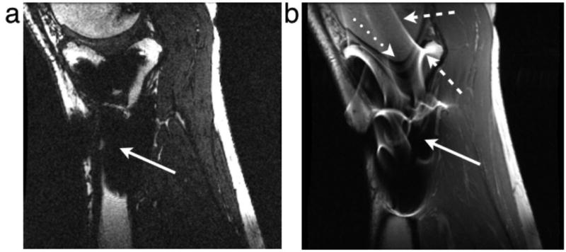
The magnetic field variations cause large resonant frequency variations, resulting in a variety of artifacts in MR imaging. When the field changes rapidly with position, there is significant dephasing of the signal, resulting in signal loss. This static effect can be avoided by using spin echo sequences or sometimes by using very short echo-time gradient echo sequences. The frequency variations can also prevent successful use of fat-suppression techniques that are based on the chemical shift, or frequency difference between fat and water tissues. In both the slice selection and readout directions, frequency variations result in displacement of signal. Because the frequency varies spatially, signal can be shifted away from regions, resulting in signal loss, or can accumulate in one region, resulting in a “pile-up” artifact. In less extreme situations, the varying displacements result in geometric distortion of the image. Several of these artifacts are illustrated in Fig. 1.
Figure 1.
Examples of artifacts due to the presence of stainless steel screws in (a) gradient echo image with ±62.5 kHz receive bandwith and (b) spin echo image with ±16 kHz receive bandwidth. Solid arrows show signal loss that can be due to dephasing, or from signal being shifted away from a region. The dotted arrow shows geometric distortion of the femoral condyle. Dashed arrows show signal pile-up, which can be a combination of in-plane and through-slice displacement of signal from multiple locations to one position.
In this article, we review some of the basic principles of imaging, and how metal-induced susceptibility artifacts are manifested in images. We describe common ways to reduce or modify artifacts using readily-available imaging techniques. Next we describe advanced methods to correct readout-direction artifacts, and slice-direction artifacts. Although technical, this article focuses on practical methods and techniques of artifact reduction. More advanced methods as well as thorough physical explanations of the origin of susceptibility artifacts have been recently described [10].
Imaging Mechanisms
This section briefly reviews the physics of MR imaging to explain why the presence of metal causes artifacts in imaging. MR imaging is enabled by first polarizing nuclear spins, typically in a static magnetic field. At macroscopic levels, the nuclear spins are collectively referred to as magnetization, which is a vector quantity. The magnetization can be excited, or actively rotated away from the direction of the static magnetic field to point in a transverse direction by a radiofrequency (RF) magnetic field. The transverse magnetization then precesses or resonates around the direction of the static field, which can generate an RF signal in a receive coil. The use of gradient fields can change the precession rate as a function of position in an arbitrary direction, allowing image formation in arbitrary scan orientations.
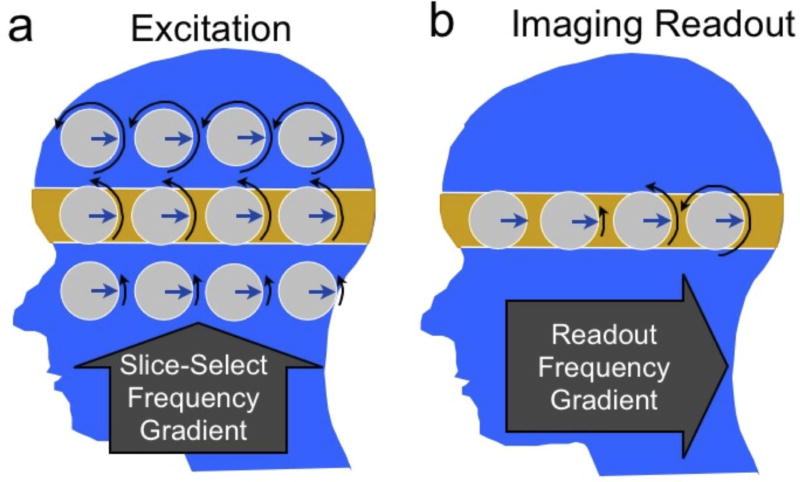
Most MR imaging methods consist of exciting the magnetization in slices, and forming 2D images of each slice. Excitation is achieved by first using a slice select gradient that imposes a variation of precession rate (or resonance frequency) in the slice direction (Fig. 2a). Next, an RF magnetic field is generated, with a limited bandwidth around a center frequency that is chosen so as to excite magnetization at a particular position. This is analogous to setting the dial on an amplitude-modulation (AM) radio to tune to a particular radio station. In MRI, after the spins within the slice have been excited, the excitation gradient is turned off, and the variation of precession rate in the slice direction is removed.
Figure 2.
Magnetization dynamics during slice selection (a) and imaging readout (b). The magnetization precession rate or frequency is indicated by black arrows showing different amounts of phase (rotation). To excite the highlighted slice (a), a gradient is turned on in the slice-select direction (superior-inferior) to impose a frequency variation. A radiofrequency (RF) pulse excites the magnetization at the frequency of the desired slice. Once the slice has been excited (b), the slice-select gradient is turned off, and a gradient is turned on in the readout or “frequency-encode” direction (anterior-posterior). This imposes a frequency variation with position. The received signal then consists of multiple frequencies, the strength of which depend on the amount of signal at the corresponding position.
To form 2D images, a gradient field can be turned on in a direction within the plane of the slice, causing a variation of the precession rate (Fig. 2b). The received signal is acquired during this time. The individual frequencies (or “tones”) can assigned to specific image locations using a method called a Fourier transform, with the amplitude of each frequency corresponding to the strength of the magnetization at a particular position. This process, called frequency encoding is analogous to hearing a piano sound: If several keys are pressed on a piano with different strength, the strings cause a vibration in your ear, analogous to the MRI signal that is recorded. Your ear is able to deduce the individual tones as well as the strength of each, much like the Fourier transform process deduces signal from different locations.
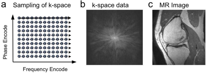
During frequency encoding, the received signal is actually sampled at discrete time points, with the change between points due to the position and the area of the gradient waveform between samples. Unlike frequency encoding, phase encoding switches on a gradient for a finite time, then switches off before acquiring samples. On successive excitations, the amplitude of the gradient can be changed. This allows sampling of the 2D data space called k-space, as shown in Fig. 3. The Fourier transform can be applied in two directions, leading to a 2D image. A key distinction between phase-encoding and frequency-encoding is that for phase-encoding the time that a particular sample is acquired does not depend on the sample position in the phase encode direction.
Figure 3.
In conventional MRI, samples of data are acquired in “k-space.” (a). On each excitation samples are taken along a line of locations in the frequency-encode direction over time (solid, dashed arrows). On different excitations, the location of these samples in the phase-encode direction is changed. The sampled data in k-space (b) consists of signal strengths at each location, and can be Fourier transformed to obtain the corresponding image (c).
While the raster scanning of k-space using frequency and phase encoding (Fig. 3) is by far the most common method of acquiring MR images, other options exist. Just as phase encoding moves to a different sample position in k-space, any combination of gradients can be used to move to any position. Sampling several lines of k-space on one excitation using echo-planar imaging (EPI) is a common option [11]. Alternatively, sampling with a radial [12] or spiral [13] pattern are also used for certain applications. These “non-Cartesian” sampling methods have advantages and disadvantages compared with raster scanning, and the artifacts due to the presence of metal may be differ substantially from those discussed here for Cartesian scanning methods.
Image Artifacts Near Metal Implants
The most prominent image artifacts that occur when imaging near metal arise from the inhomogeneous static magnetic field, which causes large variations in the precession rate (or resonant frequency) across the object. The predominant artifacts that arise in imaging are signal loss due to dephasing, failure of fat suppression, and displacement artifacts. Displacement artifacts occur in the slice selection and readout directions and include geometric distortion, signal loss and signal “pile-up.”
Close to metal objects, the magnetic field variations can be very rapid, such that the magnetization within a single imaged voxel precesses at varying rates. This leads to dephasing or loss of coherence, and signal loss. In images, this manifests as a black area where there would otherwise be signal (Fig. 1). Fortunately, dephasing effects can be almost completely avoided by the use of spin echo imaging, as described below.
Aside from the distortion and dephasing artifacts described above, an important detrimental effect of imaging near metal is failure of fat suppression. Many fat suppression techniques are far more sensitive to magnetic field variations than the image-formation methods themselves. The most common method of fat suppression is to use a chemically-selective saturation, often called fat saturation [14]. This method selectively excites fat exploiting the fact that the fat resonance is 220 Hz below that of water at 1.5 T. The frequency shifts near metallic implants can range from about 3 kHz to 80 kHz. This can cause large changes in the fat resonance, easily enough to cause complete failure of fat saturation as the saturation pulse completely misses the resonance frequency of fat near metal.
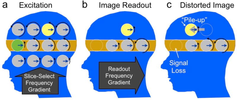
As described above, the method of selectively exciting a 2D slice in MRI is to apply an RF magnetic field of finite bandwidth in the presence of a gradient field. Since the gradient maps position to resonant frequency, the slice position is determined by changing the frequency of the RF field. When there are variations in the static magnetic field, these cause an error in the position that is selected. The error can cause a shift in the excited slice, or a curving or “potato-chip” effect. It can also cause the slice to be thicker or thinner than desired, and can even result in splitting of the slice into multiple regions. The overall result is that the selected region differs from what was desired, and therefore, the desired slice position no longer represents the location of the image. While small shifts or curving of the slice may not be noticeable, the thinning and thickening lead to clear signal loss or pile-up effects, the mechanisms of which are shown in Fig. 4. Using the radio-tuning analogy, the presence of the metal effectively causes some radio stations to transmit at the wrong frequency, so that when you tune to a location you may (a) miss the station you are looking for, (b) hear the wrong station or (c) hear multiple stations that are transmitting on the same channel.
Figure 4.
The effect of an offset of the resonance frequency or “off-resonance” on slice selection (a) and imaging readout (b). During slice selection, the yellow and green spins resonate below the expected rates. When the RF pulse is centered at the rate of the gray spins in the orange region, the green spin is not excited, while the yellow one is excited, resulting in signal loss (green) and pile-up (yellow). Next, when the spins are imaged, the yellow spin will again resonate below the expected rate (b), and be detected at the incorrect postion in the A/P direction (c), resulting in in-plane pile-up artifact. Note that although just a few spins are shown here to illustrate the concept, there is actually a continuous distribution of magnetization in both directions and the excited slice can show displacement, broadening, thinning or even splitting depending on the off-resonance frequency distribtuion.
During the image acquisition, in the frequency-encoding direction, a gradient field is played to map position to particular precession rates of the magnetization. The reconstruction inverts this process by identifying the tones in the signal, with each tone corresponding to a position. However, variations in the static magnetic field cause shifts in these tones, which again result in an error in determining the position from which the signal originates. Like slice distortion, the variations can result in bulk shifts that can distort the image, or in more extreme cases signal loss or pile-up effects when the signal is shifted away from a position or when signal from multiple positions is shifted to one position. The mechanism of slice-select and frequency-encode distortion are shown in Fig. 4. Note that the frequency-encode-direction and slice-direction artifacts are difficult to separate as both result in geometric distortion, signal loss and signal pile-up effects. Using the piano analogy, the static field variations simply cause the piano to be grossly out of tune and generate the wrong sounds for certain keys. A listener trying to identify the tones will make errors that correspond to shifts of signal to and from different positions in the image. In extreme cases, one key may generate the tone of the adjacent key, resulting in perception of increased signal at that tone (pile-up) or loss at the missing tone.
Basic Reduction of Artifacts
Although artifacts near metal can be severe, it is important to realize that many standard techniques and careful parameter selections can be combined to mitigate them, often to the point that an image has diagnostic value in spite of artifacts. The main types of artifacts, and both basic and advanced methods to reduce them are summarized in Table 1.
Table 1.
Common artifacts in MRI due to the presence of metallic implants, and methods to reduce them, as described in detail in the text. Standard methods are widely available, while more advanced methods are generally in research phases.
| Artifact | Standard Methods to Reduce Artifact |
Advanced Methods to Reduce Artifact |
|---|---|---|
| Signal Loss from Dephasing | Spin Echo or Fast Spin Echo (FSE/TSE/RARE) | Ultrashort Echo-Time Sequences, SWIFT |
| Failure of Fat Suppression | Use of STIR imaging, or Dixon techniques (less effective) | |
| Geometric Distortion | High readout bandwidth | View-Angle Tilting Field-map based corrections |
| In-Plane Distortion (Pile-up and Signal Loss) | High readout bandwidth Swap frequency/phase | View-Angle Tilting |
| Through-Slice Distortion | Non-selective Imaging Thin slices | (See below) |
| All distortions | (See Combinations above) | Multi-spectral Imaging (MAVRIC, SEMAC, etc) |
The signal dephasing that occurs when the static magnetic field varies rapidly results in dark areas of signal loss. The most common way to avoid this is to use spin echo techniques, which use a 180° “refocusing” pulse that reverses static field dephasing. As shown in Fig. 1, the spin echo avoids much of the signal loss seen with gradient echo imaging. An alternative to using spin echoes is to use ultrashort echo time (UTE) methods where the imaging is performed immediately after the RF excitation so that there is less time for magnetization to become incoherent (or dephase).
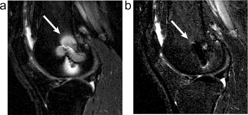
The failure of fat suppression can be reduced in many cases by the choice of fat suppression technique. Common MRI fat suppression methods include spectrally-selective saturation [14], short-TI inversion recovery (STIR) [15], or multiple-echo separation techniques such as Dixon separation [16, 17]. Fat suppression or water-only excitations are the most sensitive to the presence of metal, and will fail any time the shim is insufficient to remove background frequency variations to within the chemical shift frequency difference between fat and water. Dixon techniques can track gradual magnetic field variations, and perform well some distance from metal where fat-saturation may fail. However, closer to the metal, even Dixon techniques fail, and the best choice is to use STIR imaging, since it is completely independent of resonance frequency. STIR uses an inversion-recovery approach to null fat based on its short T1 relaxation time, which provides much more homogeneous fat suppression near metal as shown in Fig. 5. There are two down sides of using STIR. First it is limited by low SNR because the inversion pulse causes attenuation of the non-fat signal. Second, when a contrast agent is used, the tissue that normally enhances would instead be suppressed because of the shortened T1. Therefore, for contrast-enhanced imaging in the presence of metal, the options are very limited. Dixon-based methods are probably the best option, but will certainly fail near larger implants.
Figure 5.
Conventional fat-saturated (a) and STIR (b) proton-density weighted images of the knee of a patient with a titanium screw present. Fat-saturation leads to imperfect fat suppression near the metal, but maintains SNR. STIR provides uniform fat suppression, but decreases SNR, and still shows some pile-up artifacts around the metal.
The spatial distortion in the slice direction (Fig. 4) is the ratio of frequency offset to slice bandwidth, multiplied by slice width. Therefore using thin slices will reduce the amount of this distortion. The cost of this is both increased scan time since more slices are required to adequately cover the volume of interest and reduced SNR because the voxel size has been reduced. Multiple slices can be averaged during post-processing in order to recover some SNR, but this technique still reduces the overall SNR efficiency by a factor of 0.7. Nonetheless, the use of thin slices is a viable distortion-reducing option that can by used on most scanners.
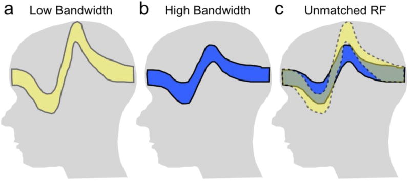
A direct way to reduce distortion effects is to maximize the bandwidth used both on slice selection and during readout. On both slice selection and readout, the spatial distortion is inversely proportional to the gradient strength, which scales with the bandwidth. Some systems will allow the use of increased bandwidth RF slice selection pulses, which will thus reduce slice distortion, as shown in Fig. 6. Increased RF bandwidth, however, comes at a cost of increased power deposition (SAR), which may either force longer repetition times or fewer interleaved slices per repetition.
Figure 6.
Use of a low slice-selection bandwidth results in substantial slice distortion or “potato-chipping” in the presence of frequency variations (a). Use of a higher excitation pulse bandwidth decreases the disotortion (b), but at a cost of higher RF power. An option to reduce image distortion is to use unmatched bandwidths on the excitation and refocusing pulses so that only the overlapped region is imaged (c). This may reduce some artifact, but can also result in signal loss.
As with slice selection, maximizing the readout bandwidth will minimize displacement artifact in the readout direction. The number of pixels of in-plane displacement is simply the ratio of the frequency offset to the bandwidth-per-pixel. (Note that on many systems, the readout bandwidth is specified using the half-bandwidth over the FOV. The pixel bandwidth is the twice the half-bandwidth, divided by the readout matrix size.) As with the slice-selection bandwidth, increasing the readout bandwidth comes at a cost - SNR. Maximizing readout bandwidth does reduce echo spacing which leaves an option for longer echo trains to partly compensate for lost efficiency. Next to using spin-echo methods, maximizing readout bandwidth is probably the simplest way to dramatically reduce artifacts near metal.
Most conventional imaging sequences will suffer from displacement artifacts in both the slice-select direction and the readout direction, but not in the phase-encode direction. In 3D sequences, although there are two phase-encode directions, there is typically a slab-selective excitation that has very large distortions due to the fact again that the distortion is proportional to the slice (or slab) thickness. However, if a non-selective pulse is used with 3D sequences, there will indeed be two phase-encode directions, neither subject to displacement artifacts. In certain imaging scenarios, the phase-encode direction(s) can be positioned in the direction perpendicular to interfaces so that the interfaces can still be clearly seen in spite of artifacts [18, 19].
Recall that the displacement due to off-resonance effects during excitation is inversely proportional to the RF bandwidth. In the common case, where spin echo sequences are used, an option is to use a different RF bandwidth for the excitation and refocusing pulses. This causes a different displacement for the excited and refocused slice in the presence of frequency offsets (Fig. 6). The result is that no signal arises from the off-resonant tissue, because it is not refocused. This approach is similar to inner-volume imaging, where the region is limited by changing the spatial region that is excited and refocused. The use of differing bandwidths has the tradeoff that artifacts may be suppressed, but at a cost that some signal is lost. In addition, the different excitation/refocusing regions can result in increased saturation of adjacent slices, which may force increased scan times, larger slice gaps, or other compromises. Differing excitation/refocusing pulse bandwidths are already used in cases to reduce artifacts from gradient non-linearity, and also may be used where the refocusing pulse bandwidth is reduced because of peak RF limits. However, more recently this concept has been used specifically to reduce artifacts near metal implants [20].
In-Plane Artifact Reduction
The in-plane artifacts due to displacement include geometric distortion, and in more severe cases, signal loss and pile-up artifacts. Although maximizing bandwidth is helpful in all cases, there are other options that can improve quality further.
The displacements due to off-resonance are predictable if the frequency error is known. In cases of fairly smooth frequency error, the geometric distortion can be largely fixed. The key assumption to this approach is that the frequency changes can be resolved by the image resolution, or put another way, that one frequency offset is representative for each voxel. The process then consists of measuring this frequency offset using field-mapping techniques, typically with multiple echo times. The image can then be distorted in the reconstruction to correct the geometric distortions that result from frequency offsets.
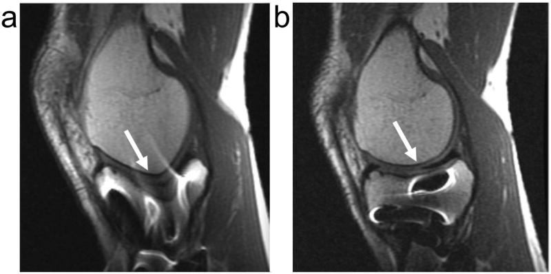
Field mapping is unable to resolve the very rapid spatially-varying frequency offsets that lead to pile-up and signal loss. A method called view-angle tilting (VAT) can be quite powerful in this situation [21]. VAT takes advantage of the fact that both the slice displacement and in-plane displacement due to off-resonance are known, and have a constant ratio. VAT replays the slice-selection gradient during the readout, which shears the image. The result is that slice-displacements exactly cancel in-plane displacements, so the in-plane displacements are removed, as shown in Fig. 7. However, VAT does not fix the slice distortion. Note that an alternative view of VAT is that the RF excites a certain bandwidth. By replaying the slice select gradient, the off-resonance is limited to the RF bandwidth, and in-plane distortion is nearly removed [22]. A limitation of VAT, however, is that the readout duration is limited to that of the RF excitation otherwise blurring can result [23]. This limits the SNR or spatial resolution that can be achieved. To avoid this blurring and to minimize residual artifact from the voxel tilt, a high bandwidth readout is desirable when using VAT [24].
Figure 7.
Spin echo (a) and VAT (b) images of a subject with stainless steel screws in his tibia, using identical parameters. Note the geometric distortion is completely corrected in VAT (arrows) but the through-slice signal loss and pile-up artifacts remain (bright areas in tibia).
One approach that has been used to reduce in-plane artifacts is to limit the excited bandwidth. This can be achieve using a spectral-spatial excitation, which excites both a limited slice and a limited band of frequencies. Because the frequency range is limited, this limits the in-place artifact. The cost of this approach is that the excitation must be repeated for different frequencies, which costs scan time.
Through-Plane Artifact Reduction
Slice direction distortion is a challenge, as maximizing RF bandwidths is ultimately limited by the maximum RF amplitude as well as the RF power or specific absorption rate (SAR). Methods have been designed to correct linear field variations in the slice direction. Gradient-echo slice excitation profile imaging (GESEPI) uses slice-direction phase-encoding and a Fourier transform, to recover signal losses in each slice [25]. 3D z-shimming builds on this with more efficient sampling based on expected field variations [26]. An alternative approach is to acquire and use a field map to estimate the slice displacement and thickening/thinning, which can be corrected in some cases [27]. More recently, methods have built on these techniques to correct a much more arbitrary range of resonance frequency offsets near metal, as described in the remainder of this section.
Multi-acquisition variable resonance image combination (MAVRIC) is a method to correct both in-plane and through-slice displacement artifacts [28]. MAVRIC uses a frequency-selective excitation (rather than exciting a slice or slab) to limit the range of frequency offsets imaged at one time. This is followed by a standard 3D imaging readout, typically using a spin echo train. As described before, when the range of frequencies is limited, the in-plane displacement is also limited, to within about a pixel in this case. MAVRIC avoids slice-direction displacements by using phase encoding to resolve in this direction. The 3D images are repeated for a range of frequencies, and combined together, typically using a sum-of-squares operation. The combined images have minimal artifact, and include signal from a wide range of frequency offsets near metal.
Slice-Encoding for Metal Artifact Correction (SEMAC) also corrects both in-plane and through-slice distortions near metal [29]. In SEMAC, 2D slices are excited just as in a standard multislice sequence, resulting in distorted profiles. For each slice, a 3D image is formed, using VAT to avoid in-plane artifacts and phase-encoding in the other two directions to avoid distortion. By combining the 3D images for each slice, a distortion-corrected volume can be achieved.
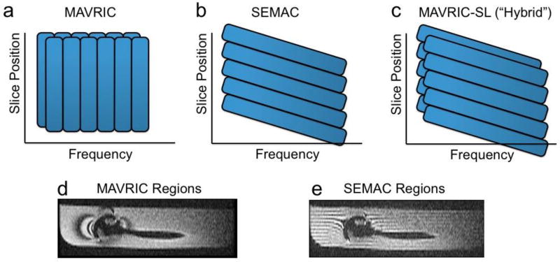
MAVRIC and SEMAC are very similar in many respects. Both use multiple excitations in order to excite the overall volume being imaged, and both use a 3D spin echo acquisition to resolve through-plane distortion. In both cases, the residual distortion in the readout direction is identical, within about a pixel. The fundamental difference between the techniques is that MAVRIC excites limited frequency bands, whereas SEMAC excites limited spatial bands. However, note again that the spatial bands are distorted by frequency offsets. There are other implementational differences including whether the excitation bands overlap, but these can typically be applied equally to both methods. A hybrid MAVRIC-SEMAC approach merges features from both original methods into one sequence [30]. Figure 8 shows how individual regions are excited in MAVRIC, SEMAC and the hybrid technique, while Fig. 9 shows example images using all of these methods.
Figure 8.
The excited regions of (a) MAVRIC and (b) SEMAC differ in that MAVRIC is purely frequency selective, while SEMAC is spatially selective, but with shifts due to frequency. The original MAVRIC method proposes overlapped regions, which improves artifact suppression at a cost of time. (c) A hybrid approach uses spatially-selective excitation, but overlapped regions. In a phantom with a shoulder prosthesis, the regions can be illustrated by intentionally leaving space between regions and showing reformatted images (d,e). In MAVRIC (d), the regions follow the contours of the magnetic field variations, while in SEMAC (e) the regions are distorted (“potato-chipped”) slices.
Figure 9.
Example images using (a) spin echo, (b) SEMAC, (c) MAVRIC and (d) a MAVRIC-SEMAC-hybrid approach in a subject with a total knee arthroplasty. The signal loss and pile-up artifacts in the spin echo image are substantially reduced in with the three correction techniques (b–d), with a similar overall ability to depict tissue near the implant.
Other methods have also recently been proposed for imaging near metal. Ultrashort echo time (UTE) methods and swept imaging with Fourier Transform (SWIFT) are alternatives to spin echo methods for avoiding static dephasing [31, 32]. Both methods typically use a radial acquisition, which results in blurring, but near metal more extreme additional displacement and pile-up artifacts. As with other methods, for a high readout bandwidth these artifacts can be reduced [33], but have not been compared directly with MAVRIC or SEMAC. Furthermore, the very short echo times may allow visualization of the polyethylene spacer, which could have diagnostic value [34]. The non-Cartesian methods add additional implementational complexity, which also has limited their use for routine scanning.
Summary
Although some metallic implants are safe for MR imaging, their presence can cause substantial artifacts in images including signal loss, failure of fat suppression, geometric distortion and signal pile-up. Signal loss caused by static dephasing can largely be corrected by the use of spin echoes, while some distortion can be reduced by the choice of scan parameters. Fat suppression failure is mitigated by using Dixon-based techniques, or better yet, STIR imaging at a cost of SNR. Displacement artifacts that cause geometric distortion, signal loss and pile-up can be corrected with a variety of methods. View-angle tilting is effective for in-plane displacement artifacts. However, much more complete correction, including correction for both in-plane and through-slice displacements, can be achieved by multi-spectral imaging methods such as MAVRIC or SEMAC, but at a cost of increased scan time. All of these methods are now, or soon will be fairly readily available on most scanners. Overall, it is important to understand the cause of metal-induced artifacts and to select the most appropriate of the available options to reduce or avoid them in the particular application.
Contributor Information
Brian Hargreaves, Stanford University.
Pauline W. Worters, GE Healthcare
Kim Butts Pauly, Stanford University.
John M. Pauly, Stanford University
Kevin M. Koch, Medical College of Wisconsin
Garry E. Gold, Stanford University
References
- 1.Elixhauser A, Andrews RM. Profile of inpatient operating room procedures in US hospitals in 2007. Arch Surg. 2010;145:1201–1208. doi: 10.1001/archsurg.2010.269. [DOI] [PubMed] [Google Scholar]
- 2.Javid M, Hadar E. Long-term follow-up review of patients who underwent laminectomy for lumbar stenosis: a prospective study. Journal of Neurosurgery: Pediatrics. 1998;89 doi: 10.3171/jns.1998.89.1.0001. [DOI] [PubMed] [Google Scholar]
- 3.Mekhail N, Wentzel D, Freeman R, Quadri H. Counting the Costs: Case Management Implications of Spinal Cord Stimulation Treatment for Failed Back Surgery Syndrome. Professional Case Management. 2011;16:27. doi: 10.1097/NCM.0b013e3181e9263c. [DOI] [PubMed] [Google Scholar]
- 4.Ryken T, Eichholz K, Gerszten P, Welch W, Gokaslan Z, Resnick D. Evidence-based review of the surgical management of vertebral column metastatic disease. Neurosurgical Focus. 2003;15:1–10. doi: 10.3171/foc.2003.15.5.11. [DOI] [PubMed] [Google Scholar]
- 5.Kurtz S, Ong K, Lau E, Mowat F, Halpern M. Projections of primary and revision hip and knee arthroplasty in the United States from 2005 to 2030. The Journal of Bone and Joint Surgery. 2007;89:780. doi: 10.2106/JBJS.F.00222. [DOI] [PubMed] [Google Scholar]
- 6.Kanal E, Shellock F, Talagala L. Safety considerations in mr imaging. Radiology. 1990;176:593. doi: 10.1148/radiology.176.3.2202008. [DOI] [PubMed] [Google Scholar]
- 7.Wildermuth S, Dumoulin C, Pfammatter T, Maier S, Hofmann E, Debatin J. Mr-guided percutaneous angioplasty: assessment of tracking safety, catheter handling and functionality. Cardiovascular and interventional radiology. 1998;21:404–410. doi: 10.1007/s002709900288. [DOI] [PubMed] [Google Scholar]
- 8.Nitz W, Oppelt A, Renz W, Manke C, Lenhart M, Link J. On the heating of linear conductive structures as guide wires and catheters in interventional mri. Journal of Magnetic Resonance Imaging. 2001;13:105–114. doi: 10.1002/1522-2586(200101)13:1<105::aid-jmri1016>3.0.co;2-0. [DOI] [PubMed] [Google Scholar]
- 9.Schenck JF. The role of magnetic susceptibility in magnetic resonance imaging: MRI magnetic compatibility of the first and second kinds. Med Phys. 1996;23:815–850. doi: 10.1118/1.597854. [DOI] [PubMed] [Google Scholar]
- 10.Koch K, Hargreaves B, Pauly K, Chen W, Gold G, King K. Magnetic resonance imaging near metal implants. Journal of Magnetic Resonance Imaging. 2010;32:773–787. doi: 10.1002/jmri.22313. [DOI] [PubMed] [Google Scholar]
- 11.Mansfield P. Multiplanar image formation using NMR spin-echoes. J Phys Chem Solid State Phys. 1977;10:L55. [Google Scholar]
- 12.Lauterbur P, Lai C. Zeugmatography by reconstruction from projections. Nuclear Science, IEEE Transactions on. 1980;27:1227–1231. [Google Scholar]
- 13.Meyer CH, Hu BS, Nishimura DG, Macovski A. Fast spiral coronary artery imaging. Magn Reson Med. 1992;28:202–213. doi: 10.1002/mrm.1910280204. [DOI] [PubMed] [Google Scholar]
- 14.Keller PJ, Schmalbrock P. Multisection fat-water imaging with chemical shift selective presaturation. Radiology. 1987;164:539–541. doi: 10.1148/radiology.164.2.3602398. [DOI] [PubMed] [Google Scholar]
- 15.Bydder GM, Pennock JM, Steiner RE, Khenia S, Payne JA, Young IR. The short TI inversion recovery sequence – an approach to MR imaging of the abdomen. Magn Reson Imaging. 1985;3:251–254. doi: 10.1016/0730-725x(85)90354-6. [DOI] [PubMed] [Google Scholar]
- 16.Dixon WT. Simple proton spectroscopic imaging. Radiology. 1984;153:189–194. doi: 10.1148/radiology.153.1.6089263. [DOI] [PubMed] [Google Scholar]
- 17.Glover GH. Multipoint Dixon technique for water and fat proton and susceptibility imaging. J Magn Reson Imaging. 1991;1:521–530. doi: 10.1002/jmri.1880010504. [DOI] [PubMed] [Google Scholar]
- 18.Sofka C, Potter H, Figgie M, Laskin R. Magnetic resonance imaging of total knee arthroplasty. Clinical orthopaedics and related research. 2003;406:129. doi: 10.1097/01.blo.0000030516.43495.61. [DOI] [PubMed] [Google Scholar]
- 19.Potter H, Nestor B, Sofka C, Ho S, Peters L, Salvati E. Magnetic resonance imaging after total hip arthroplasty: evaluation of periprosthetic soft tissue. The Journal of Bone and Joint Surgery. 2004;86:1947. doi: 10.2106/00004623-200409000-00013. [DOI] [PubMed] [Google Scholar]
- 20.Bos C, den Harder CJ, van Yperen G. MR imaging near orthopedic implants with artifact reduction using view-angle tilting and off-resonance suppression. Proceedings 18th Scientific Meeting, International Society for Magnetic Resonance in Medicine; Stockholm, Stockholm. 2010. p. 129. [Google Scholar]
- 21.Cho Z, Kim D, Kim Y. Total inhomogeneity correction including chemical shifts and susceptibility by view angle tilting. Medical Physics. 1988;15:7–11. doi: 10.1118/1.596162. [DOI] [PubMed] [Google Scholar]
- 22.Olsen RV, Munk PL, Lee MJ, Janzen DL, MacKay AL, Xiang QS, Masri B. Metal artifact reduction sequence: early clinical applications. Radiographics. 2000;20:699–712. doi: 10.1148/radiographics.20.3.g00ma10699. [DOI] [PubMed] [Google Scholar]
- 23.Butts K, Pauly JM, Gold GE. Reduction of blurring in view angle tilting MRI. Magn Reson Med. 2005;53:418–424. doi: 10.1002/mrm.20375. [DOI] [PubMed] [Google Scholar]
- 24.Kolind SH, MacKay AL, Munk PL, Xiang QS. Quantitative evaluation of metal artifact reduction techniques. J Magn Reson Imaging. 2004;20:487–495. doi: 10.1002/jmri.20144. [DOI] [PubMed] [Google Scholar]
- 25.Yang QX, Williams GD, Demeure RJ, Mosher TJ, Smith MB. Removal of local field gradient artifacts in T2*-weighted images at high fields by gradient-echo slice excitation profile imaging. Magn Reson Med. 1998;39:402–409. doi: 10.1002/mrm.1910390310. [DOI] [PubMed] [Google Scholar]
- 26.Glover G. 3D z-shim method for reduction of susceptibility effects in BOLD fMRI. Magnetic Resonance in Medicine. 1999;42:290–299. doi: 10.1002/(sici)1522-2594(199908)42:2<290::aid-mrm11>3.0.co;2-n. [DOI] [PubMed] [Google Scholar]
- 27.Butts K, Gold GE. Correction of slice profile distortions from metallic devices. Proceedings of the 14th Annual Meeting of ISMRM; Seattle. 2006. p. 2380. [Google Scholar]
- 28.Koch KM, Lorbiecki JE, Hinks RS, King KF. A multispectral three-dimensional acquisition technique for imaging near metal implants. Magn Reson Med. 2009;61:381–390. doi: 10.1002/mrm.21856. [DOI] [PubMed] [Google Scholar]
- 29.Lu W, Pauly KB, Gold GE, Pauly JM, Hargreaves BA. SEMAC: Slice encoding for metal artifact correction in MRI. Magn Reson Med. 2009;62:66–76. doi: 10.1002/mrm.21967. NIHMS171941. [DOI] [PMC free article] [PubMed] [Google Scholar]
- 30.Koch KM, Brau ACS, Chen W, Gold GE, Hargreaves BA, Koff M, McKinnon G, Potter HG, King KF. Imaging near metal with a MAVRIC-SEMAC hybrid. Magnetic Resonance in Medicine. 2010 doi: 10.1002/mrm.22523. Accepted. [DOI] [PubMed] [Google Scholar]
- 31.Gold GE, Thedens D, Pauly J, Bergman G, Beaulieu C, Fechner K, Macovski A. MR imaging of articular cartilage of the knee: New methods using ultrashort TE’s. AJR Am J Roentgenol. 1998;170:1223–1226. doi: 10.2214/ajr.170.5.9574589. [DOI] [PubMed] [Google Scholar]
- 32.Idiyatullin D, Corum C, Park JY, Garwood M. Fast and quiet MRI using a swept radiofrequency. J Magn Reson. 2006;181:342–349. doi: 10.1016/j.jmr.2006.05.014. [DOI] [PubMed] [Google Scholar]
- 33.Carl M, Du J, Koch K. Investigations on imaging near metal with combined 3D UTE-MAVRIC. Proceedings of the 19th Annual Meeting of ISMRM; Montreal. 2011. p. 2668. [Google Scholar]
- 34.Rahmer J, Bornert P, Dries S. Assessment of anterior cruciate ligament reconstruction using 3d ultrashort echo-time mr imaging. Journal of Magnetic Resonance Imaging. 2009;29:443–448. doi: 10.1002/jmri.21653. [DOI] [PubMed] [Google Scholar]


