Abstract
Cancers of the pancreas have the poorest prognosis among all cancers, as many tumors are not detected until surgery is no longer a viable option. Surgical viability is typically determined via endoscopic ultrasound imaging. However, many patients who may be eligible for resection are not offered surgery due to diagnostic challenges in determining vascular or lymphatic invasion. In this article, we describe the development of a dual-frequency piezoelectric transducer for rotational endoscopic imaging designed to transmit at 4 MHz and receive at 20 MHz in order to image microbubble-specific superharmonic signals. Imaging performance is assessed in a tissue-mimicking phantom at depths from 1.0 cm (CTR = 21.6 dB) to 2.5 cm (CTR = 11.4 dB), in ex vivo porcine vessels, and in vivo in a rodent. The prototyped 1.1 mm-aperture transducer demonstrates contrast-specific imaging of microbubbles in a 200 μm-diameter tube through the wall of a ~1 cm-diameter porcine artery, suggesting such a device may enable direct visualization of small vessels from within the lumen of larger vessels such as the portal vein or superior mesenteric vein.
Index Terms: superharmonic, microbubble, high frequency, endoscope, interventional imaging, acoustic angiography
I. Introduction
CANCERS of the pancreas occur at a rate of 4.1 new cases per 100,000 individuals per year, although the rate is much higher in some countries, including approximately twice as high in the United States [1]. The 5-year survival rate is just 7.7%, primarily because at the time of presentation, 85–90% of pancreatic tumors are inoperable due to tumor vascular invasion [1]. Patients commonly present with non-specific symptoms such as pain, weight loss, and jaundice [2], with imaging required to arrive at a diagnosis.
Initial imaging is typically performed with either transabdominal ultrasound (patients with jaundice) or computed tomography (CT, patients with epigastric pain and weight loss) [2]. If a pancreatic lesion is found, either endoscopic ultrasound or CT is used to determine the level of vascular and lymphatic involvement and assess tumor resectability. Endoscopic ultrasound provides direct visualization of the interface between the tumor and the vessel wall [3] and is more sensitive than CT for detecting vascular invasion of the portal and splenic veins [4, 5]. However, conventional endoscopic ultrasound (EUS) is limited by low specificity, particularly in assessing arterial invasion [6] and in patients with inflammatory lesions [3]. In the case where a pancreatic tumor is found and appears to be contiguous with a major vessel, additional minimally-invasive ultrasound imaging can be performed with a smaller, intravascular ultrasound (IVUS) transducer to distinguish between vascular invasion and a tumor positioned adjacent to the vessel [3, 7].
A retroactive review of 9500 patients in the United States (1995–2004) found that 38.2% of eligible patients were not offered surgical resection, and an additional 13.5% of patients did not undergo surgery for “unknown reasons” [8]. If fewer than 50% of eligible patients actually undergo surgery using conventional approaches for imaging and staging, alternative imaging techniques capable of directly visualizing tumor and healthy vasculature (especially arterial) without the confounding effect of inflammatory lesions may increase the number of patients with resectable tumors who undergo surgery.
Contrast-enhanced endoscopic ultrasound (CE-EUS) imaging has recently been proposed as an approach which allows improved visualization of vascular involvement and improved staging [9, 10]. By using contrast-specific imaging modes (i.e. pulse inversion or amplitude modulation [11]), images of vasculature can be formed using the systems and probes which are already utilized clinically for endoscopic ultrasound imaging. These studies have indicated an improved ability to distinguish between invasive tumor and inflammation (i.e. pancreatitis) and improved diagnostic accuracy in evaluating pancreatic pathologies [10, 12, 13]. While these results are very encouraging, CE-EUS imaging typically has limited resolution due to operating at frequencies <10 MHz and also suffers from tissue artifacts due to vessel walls, which produce nonlinear reflections that are incompletely cancelled by contrast-specific imaging techniques such as pulse inversion [14, 15].
Alternatively, utilizing a dual-frequency approach to contrast imaging can provide higher resolution imaging (up to 100 μm) while greatly reducing tissue artifacts [16]. Briefly, by transmitting at a lower frequency (< 6 MHz) and receiving at much higher frequencies (≥20 MHz), images can be formed from microbubble-specific signals having amplitudes many times higher than tissue signals [17, 18]. These “superharmonic” or “acoustic angiography” images of microvasculature have contrast-to-tissue ratios of ~25 dB [16, 19, 20] and can be used to quantify vascular characteristics in developing tumors [21–26]. We have also recently demonstrated the ability to use superharmonic signals to perform high resolution functional imaging, including molecular imaging [27, 28] and perfusion imaging [29].
The primary technical challenge for microbubble superharmonic imaging is the requirement for a transducer capable of transmitting at a lower frequency and receiving at a much higher frequency. While commercial transducers do not have the necessary bandwidth for receiving echoes at frequencies 3–5 times higher than the transmitted frequency, several groups have presented designs for transducers capable of operating at two frequencies for contrast imaging. Some designs for contrast imaging have interleaved elements at different frequencies in the azimuthal direction [30], while others have stacked elements of different frequencies in the elevation direction [31, 32]. Another approach for dual-frequency ultrasound probe design is to stack elements in the direction of propagation with an intervening layer to isolate acoustic reflections between low and high frequency elements [33].
In developing dual-frequency transducers for contrast imaging, our group has pursued a hybrid approach with stacked low and high frequency elements separated by an isolation layer to ensure a common focus as well as additional area in the elevation direction for low frequency elements to ensure sufficient acoustic pressures. This design utilizes a frequency-selective isolation layer (FSIL), a quarter wavelength impedance transformer that functions as an acoustic filter permitting forward propagation of low frequency waves while preventing high frequency waves from propagating backward into the low frequency element [34, 35]. Using this design, we have previously developed single element intravascular ultrasound (IVUS) transducers operating at 6.5 and 30 MHz. Several other dual-frequency transducers for contrast imaging have also been developed by our group and by others [21, 31, 35–41]. In other applications, multiple frequency transducers have been developed for tissue harmonic imaging using two piezoelectric layers which can be operated either in phase or 180° out of phase [42, 43], combined imaging-therapy transducers [44–49], or transducers designed for pushing and tracking in acoustic radiation force impulse imaging (ARFI) [50, 51].
Alternatively, others have presented transducers with extremely broad bandwidths in order to span both the low frequency (excitatory) and high frequency (receiving) regimes. Potential options for achieving necessary bandwidth include microfabricated piezoelectric composite materials [52, 53] and capacitive micromachined ultrasound transducers (CMUTs), which have exhibited −6 dB fractional bandwidths >75% and > 100%, respectively [54]. While contrast imaging with CMUTs is challenging due to their inherent non-linear operation, recently pulse sequences have been developed for non-destructive contrast-specific imaging [55–57].
In this paper we describe the first dual-frequency endoscopic transducer with special design factors (lateral dimension and resonance mode coupling) considering anatomically-imposed spatial limitations, which could provide high-resolution imaging of vascular integration without artifacts from vessel walls or inflammatory lesions, and which may in turn improve patient classification and increase the number of patients offered surgery.
II. Methods
A. Transducer Design and Fabrication
Based on previous experiments investigating the frequency dependence of microbubble superharmonic signals, it is known that the sensitivity increases with decreasing frequency [16]. However, in order to maintain adequate resolution (~1 mm for vascular imaging), the receiving frequency must be sufficiently high (λ ≈ 100 μm). As a compromise between sensitivity and resolution, a design with a transmit frequency of 4 MHz and a receive frequency of 20 MHz was pursued. For this project, a transducer having a 1.2 mm-aperture was designed in order to be able to perform both endoscopic ultrasound imaging and imaging within large vessels (e.g. portal and superior mesenteric veins via the minimally-invasive transhepatic procedure [7]). The mean diameters of the adult portal vein and superior mesenteric veins are 10.4 ± 1.6 mm and 8.1 ± 1.2, respectively [58], allowing the designed transducer to easily traverse and image from within these primary vessels as well as intraoperatively from smaller branches (e.g. superior pancreaticoduodenal veins, diameter: 2.1 ± 0.6 mm [59]).
The designed acoustic stack consisted of a rear transmitting element comprised of PZT-5H 1–3 composite (volume fraction: 60%, Blatek, Inc., State College, PA, USA). PZT-5H ceramic (CTS 3203HD, CTS Corporation, Elkhart, IN, USA) was used for the high frequency (receiving) element. For each transducer, low and high frequency elements were acoustically separated by a frequency selective isolation layer (FSIL) [33]. Briefly, for the transducer described in this work, after the frequencies of the two elements were determined based on the application, the material for the FSIL (Al2O3/Epotek 301 epoxy, Epoxy Technology, Inc., Billerica, MA, volume fraction: 25% Al2O3, particle size 0.3 μm [60]) with known properties (Table I) was selected, and the thickness was then varied using Krimholtz-Leedom-Matthaei (KLM) model simulations (BioSono KLM 2.0, Fremont, CA, USA) [61, 62]. The entire stack was modeled for the high frequency element and the central section only was modeled for the low frequency element. Matching layers for both low and high frequency elements consisted of aluminum oxide/epoxy bond mixture (acoustic impedance 5.6 MRayl [60]) and were lapped to the desired thicknesses. Ti/Au was deposited between all layers (including above and below the non-conductive FSIL) to form electrical connections. A light epoxy only backing (Epotek 301) was applied to the transmit element to ensure high transmitting sensitivity. The backing fills a semi-cylindrical volume behind the acoustic stack and has a radius of approximately 0.5 mm. Layered structures varied in length in the elevation direction in order to create exposed surfaces for electrical connections (Fig. 1A, back edge). Cables (40232-001, 50 Ω, 38 AWG, Hitachi Cable America, Manchester, NH, USA) were attached by hand to both low and high frequency elements under magnification using conductive epoxy (E-solder 3022, Von Roll Isola, Inc. New Haven, CT, USA). The completed transducer was mounted on a polyimide tube (20 AWG) and coated with a layer of parylene to provide protection from the external environment. The designed acoustic stack is shown in Fig. 1.
TABLE I.
Materials and dimensions for designed transducer
| Structure | Material | Dimension | Acoustic Impedance |
vl
(m/s) |
kt | εS33/ε0 | Attenuation(dB/cm/MHz) |
|---|---|---|---|---|---|---|---|
| Light acoustic backing | Epoxy | ~ 0.5 mm (radius) | 3.1 MRayl | 2680 | – | – | 0.46 |
| Low frequency piezoelectric element | PZT-5H 1–3 composite | 1.1 × 3.5 × 0.350 mm3 | 19.8 MRayl | 3740 | 0.65 | 660 | – |
| Low frequency matching layer | A12O3 (25%)/epoxy | 1.1 × 3.5 × 0.180 mm3 | 5.6 MRayl | 2800 | – | – | 5.3 |
| Frequency-selective isolation layer (FSIL) | Al2O3 (25%)/epoxy | 1.1 × 0.5 × 0.055 mm3 | 5.6 MRayl | 2800 | – | – | 5.3 |
| High frequency piezoelectric element | PZT-5H | 1.1 × 0.5 × 0.108 mm3 | 34.2 MRayl | 3850 | 0.50 | 1470 | – |
| High frequency matching layer | Al2O3 (25%)/epoxy | 1.1 × 3.3 × 0.038 mm3 | 5.6 MRayl | 2800 | – | – | 5.3 |
Fig. 1.
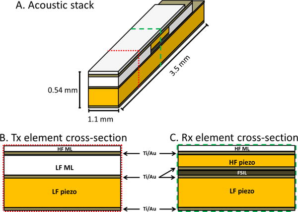
(A) Oblique and cross-sectional views of the acoustic stack, with dotted line indicating cross-sectional cut through Tx element (B) and dashed line indicating cross-section cut through Rx element (C). HF ML = high frequency matching layer, LF ML = low frequency matching layer, FSIL = frequency-selective isolation layer, Au = sputtered Ti/Au conductive layer. Further details on materials are provided in Table I.
B. Testing and characterization
Prototyped transducers were inspected under a microscope to determine the thickness and uniformity of layers (Fig. 2). An impedance analyzer was used to determine electrical impedance at resonance (Agilent 4294A, Santa Clara, CA, USA). Pulse-echo testing was performed individually on low and high frequency elements using a pulser-receiver (Panametrics 5900PR, Waltham, MA, USA) to acquire echoes from a planar aluminum reflector. Insertion loss was measured by transmitting a 5-cycle pulse into a planar aluminum reflector with a 50 Ω load applied to the waveform generator (AFG3101, Tektronix, Inc., Beaverton, OR, USA). Next, a calibrated hydrophone (ONDA HNA-0400, Sunnyvale, CA) was used to determine the peak negative transmit pressure and to map the transmitted acoustic pressure field for both elements.
Fig. 2.
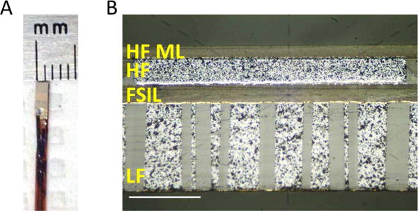
(A) Photograph of completed transducer mounted on catheter, and (B) micrograph of cross-sectional cut through center of a prototype transducer. Scale bar = 200 μm. The 1–3 composite material used for the low frequency element was cut at an angle of 60° with respect to the elevational surface seen in the photograph.
C. Phantom imaging
Imaging performance was tested using a prototype system in which the catheter-based transducer is mounted on a stepper motor to rotate the transducer through 360° with an angular step size of 0.9°. Rotation was controlled with a programmable microcontroller at a pulse repetition frequency of 100 Hz. A three-axis computer-controlled motion stage (Newport XPS, Irvine, CA, USA) translates the transducer in the elevation direction to enable 3D imaging [63]. The transducer was excited using a 4 MHz Gaussian-windowed sinusoid [19] (AFG3101) and a 60 dB radiofrequency amplifier (A-500, Electronic Navigation Industries, Rochester, NY, USA). 3D volumes of imaging data were acquired by performing pullback imaging in tissue-mimicking phantoms and in an ex vivo porcine artery. A custom tissue-mimicking phantom was fabricated (α = 0.4 dB/cm/MHz) [64] with channels having diameters of 4.0 mm and 1.0 mm in order to assess the ability to accurately image small channels. Images were acquired before and after filling the channels with 108 microbubbles/ml. Imaging experiments were performed at mechanical indices of 0.45 (4 MHz) and 0.29 (20 MHz B-mode). A second phantom was fabricated with the same attenuation having wallless 1.8 mm-diameter channels for microbubbles at depths of 1.0, 1.5, 2.0, and 2.5 cm. B-mode and dual-frequency mode imaging volumes were acquired in succession before and after filling the channels with 108 microbubbles/ml. Each acquisition consisted of 50 scans with a step size of 100 μm in the elevation direction and an angular step size of 0.9°.
D. Ex vivo artery imaging
In order to evaluate imaging performance in a scenario that more closely mimics the in vivo case, a splenic artery was obtained from a recently euthanized pig. A 200 μm-inner diameter cellulose tube was positioned adjacent to the adventitial surface of the ex vivo porcine artery. The artery was held under physiological tension using a custom holding apparatus. The entire setup was submerged in phosphate-buffered saline (PBS). A 4 mm-long section of artery was imaged first in B-mode (20 MHz), then the tube was filled with 108 microbubbles/ml and imaged again in dual-frequency mode (Tx 4 MHz, Rx 20 MHz). Angular step size was 0.9° with a step size of 100 μm in the elevation direction for both scans. RF data were filtered using a 4th order Butterworth bandpass filter (17–25 MHz) and envelope-detected in Matlab. Acquired B-mode images (gross vascular anatomy) and dual-frequency images (contrast-specific) were combined to form a single 3D dataset (ImageJ, NIH, Bethesda, MD, USA).
E. In vivo imaging
Transducer dual-frequency imaging performance was tested by performing transcutaneous imaging in a rodent with a subcutaneous tumor. Briefly, a 1-mm-diameter piece of fibrosarcoma tumor (FSA) was implanted subcutaneously in the flank of a Fischer 344 rat as previously described [65]. Imaging was performed two weeks after implantation when the tumor was 13.2 mm in diameter. The prototype transducer was mounted on a translational motion stage (Newport XPS, Irvine, CA, USA) and a custom program was used to scan the transducer in both the lateral and elevational directions in order to acquire a 3D imaging dataset (LabView, NI, Austin, TX, USA). Imaging was performed under anesthesia via vaporized isoflurane and oxygen; contrast agents were injected using a 24 gauge catheter inserted into a tail vein. Fur was removed by shaving and depilation. The center of the transducer was positioned on the center of the tumor and coupled to the animal with ultrasound gel. Microbubbles (108 microbubbles/ml) were infused at a rate of 30 μL/min using an infusion pump (Harvard Apparatus PHD2000, Holliston, MA). Acquisition time was approximately 4 minutes for a 5 mm × 5 mm scan region with a step size of 167 μm in both directions. All animal experiments were performed in accordance with the Institutional Animal Care and Use Committee of The University of North Carolina-Chapel Hill. Following image acquisition using the prototype transducer presented in this article, the animal was imaged a second time using a large mechanically-steered dual-frequency transducer (14 mm diameter, 4/30 MHz, 12.7 mm focus) described previously [36] for comparison.
III. Results
A. Modeling
Results of KLM simulations are shown in Fig. 3A and 3B. KLM simulations predicted a center frequency of 4.43 MHz and a −6 dB bandwidth of 60.9% (low frequency), and a center frequency of 21.3 MHz and −6 dB bandwidth of 64.4% (high frequency). Field II simulations predict −6 dB beam widths of 1.38 mm × 4.26 (4 MHz) and 1.64 mm × 0.70 (20 MHz)
Fig. 3.
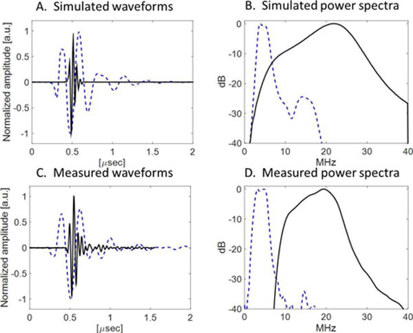
(A) Simulated pulse-echo waveforms and (B) spectra for low-frequency (dashed blue) and high frequency (solid black) elements, and (C) measured pulse-echo waveforms and (D) spectra for low-frequency (dashed blue) and high frequency (solid black) elements.
B. Transducer testing and characterization
In pulse-echo testing, measured bandwidths were 71% (4 MHz) and 55% (20 MHz) (Fig. 3C and 3D). Potential sources of discrepancy between measured acoustic characteristics in simulated and fabricated transducers include fabrication error (micro-scale thickness control), wire attachment, and a round-shaped light backing. The 1D KLM model cannot simulate the variation in the elevation direction, where only the center layer is covered by the FSIL and high frequency element, which could account for the measured bandwidth exceeding the simulated bandwidth. This model also cannot simulate the variation in thickness of the backing in the lateral direction due to the curved surface of the catheter. In hydrophone testing, a peak negative pressure of 1.38 MPa at 4 MHz (MI = 0.69) was measured in water, more than sufficient to produce the superharmonic signal from microbubbles [20]. The transmitting sensitivity was 8.2 kPa/V (peak negative pressure). −6 dB beam widths in the lateral direction were 2.55 mm at 4 MHz and 1.20 mm at 20 MHz at a depth of 10 mm (Fig. 4).
Fig. 4.
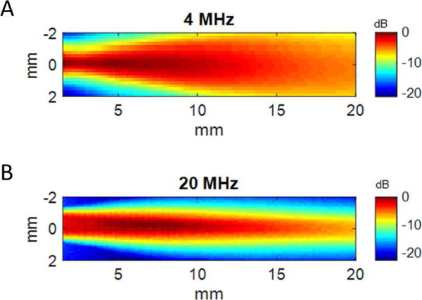
Spatial maps of acoustic pressure for the fabricated transducer for (A) 4 MHz element and (B) 20 MHz element.
C. Phantom imaging
Dual-frequency images acquired in the tissue-mimicking phantom with 1.0 mm- and 4.0 mm-diameter channels before and after contrast agent injection are shown in Fig. 5. In acquired images, channel diameters in this phantom measured 4.11 ± 0.22 mm and 1.13 ± 0.06 mm. Images from the second tissue-mimicking phantom with varying channel depths are shown in Fig. 6. Measured CTR in this phantom was 21.6 ± 4.0 dB at 10 mm, 13.7 ± 2.2 dB at 15 mm, 12.3 ± 2.5 dB at 20 mm, and 11.38 ± 1.8 dB at 25 mm (Fig. 7). In imaging ex vivo porcine arteries, the three layer structure of the arterial wall is visible in B-mode, and the microbubbles are visible in the tube 5 mm beyond the vessel wall (Fig. 8). In a second acquisition of a different arterial section, a bifurcation can be seen in the B-mode image (Fig. 9).
Fig. 5.
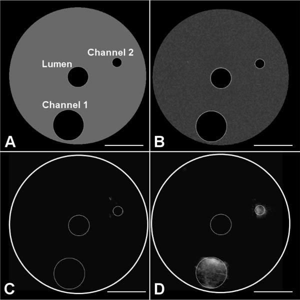
Phantom and imaging data used for assessing quantitative channel diameter measurements with the developed transducer. Channel diameters are 1.0 mm and 4.0 mm and are at depths of 6 mm and 8 mm from the transducer, respectively. (A) Phantom diagram indicating lumen for transducer and channels, (B) acquired B-mode image before injection of microbubbles into channels, (C) acquired dual-frequency image before injection of microbubbles into channels, and (D) acquired imaging volume after injection of microbubbles into channels.
Fig. 6.
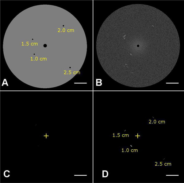
Phantom and imaging data used for assessing CTR as a function of varying depth with the developed transducer. (A) A tissue-mimicking phantom having attenuation of 0.4 dB/cm/MHz was imaged in (B) B-mode (transmit and receive 20 MHz), (C) dual-frequency mode before the injection of microbubbles (transmit: 4 MHz, receive: 20 MHz), and (D) dual-frequency mode after the injection of microbubbles. The ‘+’ indicates the transducer position. Depths of wall-less channels containing microbubbles are indicated in (A) and (D).
Fig. 7.
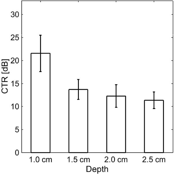
Contrast-to-tissue ratio (CTR) measurements in a tissue-mimicking phantom (Fig. 6) using the prototype transducer for dual-frequency contrast-specific imaging.
Fig. 8.
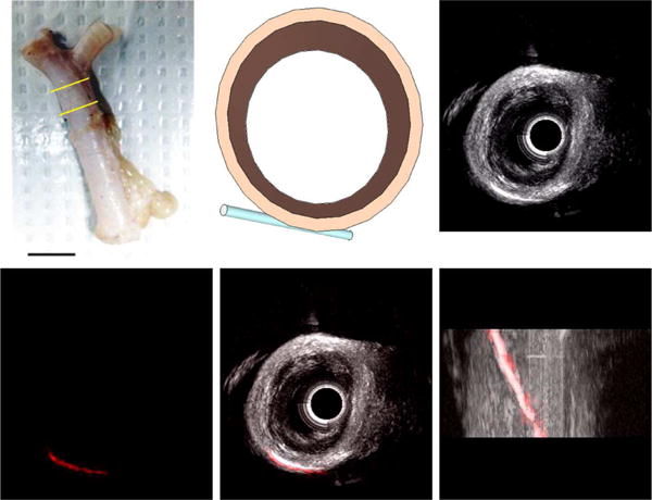
(A) Ex vivo porcine splenic artery specimen used for imaging experiments, with the imaged section indicated by yellow bars. Scale bar represents 1 cm. (B) Schematic of ex vivo artery section and cellulose tube filled with microbubbles for imaging experiment. (C) 3D rendering of B-mode (20 MHz) image acquired in arterial section (Scale bar = 2 mm). (D) 3D rendering of dual-frequency (transmit 4 MHz, receive 20 MHz) image of microbubbles in tube acquired in arterial section. Combined 3D rendering of B-mode (grayscale) and dual-frequency (red) imaging volumes shows contrast-specific signal originates only from microbubbles within the tube in (E) short and (F) long-axis views (Scale bar = 2 mm).
Fig. 9.
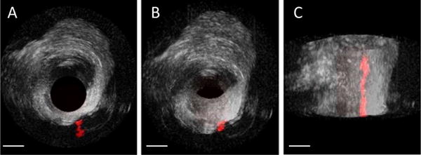
(A) Cross-sectional, (B) oblique, and (C) long-axis 3D rendered views of an arterial section having a bifurcation with an adjacent microbubble-filled tube in both B-mode (grayscale) and dual-frequency imaging modes (red) (Scale bar = 2 mm).
D. In vivo imaging
Using the computer-controlled motion stage to translate the prototype transducer, images of several vessels with contrast agent were acquired at depths reaching nearly 40 mm. However, the imaging field of view is small (5 mm × 5 mm × 40 mm) with this approach and ~4 minutes are required to acquire this data set. The correspondence between the imaging volume acquired using the prototype endoscopic transducer and the volume acquired with the larger transducer can be seen in Fig. 10. Note that vessels are visible at a depth of nearly 40 mm in (A).
Fig. 10.
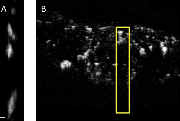
(A) 5 × 5 × 40 mm (lateral × elevational × axial) transcutaneous dual-frequency imaging volume (maximum intensity projection) acquired using the described transducer in the vasculature of a subcutaneous fibrosarcoma in a Fischer 344 rat, and (B) corresponding cross-sectional view of a dual-frequency image acquired using the large external transducer used in [21]. The yellow box in (B) indicates the region shown in (A) (Scale bar = 100 μm).
IV. Discussion
A. Future design improvements
In addition to mounting the transducer on a rotational catheter to enable minimally-invasive in vivo imaging, there are several additional improvements to transducer design which could improve performance. First, for endoscopic imaging from only the large vessels, a larger transducer could be used. The increased aperture size would lead to improved resolution, and the increased active area would increase sensitivity, however a second device would be required for minimally-invasive imaging or biopsy guidance. In this case, if a second transducer were to be developed for transhepatic access alone, a transducer having a smaller dimension in the elevation direction would be preferable in order to improve the ability to traverse tortuous arteries having small diameters, though this reduction in the active area of the transmit element would make it more difficult to achieve the necessary peak acoustic pressures. This potential loss of transmit pressure could be compensated by improving electrical matching of the transmit element to the system or using a higher efficiency piezoelectric material, such as PMN-PT single crystals.
The transducer presented in this paper has sufficient sensitivity and resolution for superharmonic contrast imaging of vessels of interest (e.g. infiltrating vessels of the superior mesenteric vein, portal vein and their branches). However, its clinical utility might be improved by increasing spatial resolution in order to resolve small vessels in the region between tumor and normal tissue. Previous studies using X-ray micro-computed tomography (micro-CT) in a rodent model indicate that pancreatic tumors have a sparse, irregular vessel network, while the region between the normal pancreas and the tumor has dense microvasculature [66]. In particular, higher resolution may improve the ability to definitively image invasive tumors and avoid unnecessary surgeries. There are several potential strategies for increasing spatial resolution, including the aforementioned increase in aperture size. The simplest approach is to increase the frequency of the receiving element, although this would also yield a reduction in CTR [16]. Decreases in CTR could be offset by improving acoustic matching to tissue via additional matching layers. Alternatively, we have also recently presented a new signal processing strategy for increasing spatial resolution by ~30% in rotational ultrasound imaging [67]. In addition, fabricating a dual-frequency endoscopic array rather than a radial endoscope could enable imaging of microbubble dynamics and improve depth of field while also yielding higher resolution throughout a larger imaging field of view, though it would come at increased fabrication cost.
B. Benefit for clinical staging of pancreatic disease
Because endoscopic ultrasound is already used clinically for pancreatic imaging via both esophageal [6] and minimally-invasive transhepatic approaches [3, 7], the only logistical change to the existing clinical procedure would be placement of an intravenous (IV) line followed by bolus injection of microbubble contrast agent. Cost and accessibility of the new devices that enable the type of contrast imaging shown in this article represent additional obstacles to adoption. The additional fabrication costs associated with a dual-frequency radial endoscope lie primarily in the acoustic stack, as the catheter assembly and receiving electronics are similar to those in existing endoscopes. Contrast mode imaging as presented in this article enables several additional capabilities, including the ability to acquire biopsy samples from the vessel wall while in contrast mode and excellent arterial imaging due to rapid microbubble reperfusion in large arteries (B-mode endoscopic ultrasound struggles with arterial imaging [6]). Thus this type of transducer has greater diagnostic function than current endoscopes, which typically utilize a single low frequency (≤12 MHz), and may also help reduce the number of return visits arising from inadequate biopsy sampling, an important cost-saving consideration given that diagnosing pancreatic cancer can require 3 months and the misdiagnosis rate is 31% [68].
V. Conclusion
We have demonstrated the feasibility of a prototype dual-frequency (4/20 MHz) endoscopic transducer for both conventional (20 MHz B-mode) and superharmonic (4/20 MHz) imaging in a tissue-mimicking phantom and in ex vivo arteries. The lower frequency design of this transducer relative to dual-frequency IVUS transducers (6.5/30 MHz) [35] enables higher CTR and greater depth of penetration at the cost of resolution. However, resolution is sufficient for the task of visualizing the continuity of healthy and tumor vasculature at depths of 1–3 cm.
TABLE II.
Characteristics of the transducers evaluated in imaging experiments
| Transmitting PZT 1–3 composite | Receiving PZT ceramic | |
|---|---|---|
|
Aperture (lateral × elevation) |
1.1 mm × 3.5 mm | 1.1 mm × 0.5 mm |
| Center frequency | 4.20 MHz | 19.50 MHz |
| −6 dB bandwidth | 71% | 55% |
| Capacitance (1 kHz) | 263.2 pF | 437.8 pF |
| Dielectric loss (1 kHz) | 0.0147 | 0.0231 |
| Insertion loss | −36.9 dB | −25.1 dB |
Acknowledgments
The authors thank Wei-Yi Chang for his help with gold deposition, Sibo Li for fabrication advice, Tim Nichols, M.D., for providing the porcine arteries, and Sarah Shelton for help with in vivo studies.
This work is supported by grants F32EB018715 and R01EB015508 from the U.S. National Institutes of Health.
Biographies

Brooks D. Lindsey (S′10, M′13) was born in Liberty, MO. He received the B.S. degree in electrical engineering from the University of Illinois at Urbana-Champaign and the Ph.D. degree in biomedical engineering from Duke University, Durham, NC, for his work in real-time 3D transcranial ultrasound imaging. While at Duke, he was the recipient of a pre-doctoral fellowship in medical imaging from the National Institutes of Health. In 2013, he joined the Joint Department of Biomedical Engineering at the University of North Carolina-Chapel Hill and North Carolina State University as a postdoctoral research associate. While a postdoc, he received the Ruth L. Kirschstein National Research Service Award from the National Institutes of Health. His research interests include interventional and functional imaging, transducer and system development, and ultrasound signal processing. Dr. Lindsey serves as a reviewer for several journals including IEEE Transactions on Ultrasonics, Ferroelectrics, and Frequency Control, IEEE Transactions on Medical Imaging, and Ultrasound in Medicine and Biology.

Jinwook Kim received his B.S. and M.S. degrees in mechanical engineering from Kyungpook National University in 2010 and 2012, respectively, working on design and optimization of underwater transducers. In 2013, he joined Dr. Xiaoning Jiang’s Micro/Nano Engineering Lab at North Carolina State University, working on the design and fabrication of ultrasound transducers for diagnosis and noninvasive therapy. His broad research interests involve laser-generated ultrasound, ultra-sound-mediated therapies, and bio-sensors.

Paul A. Dayton received his B.S. degree in physics from Villanova University in 1995, his M.E. degree in electrical engineering from the University of Virginia in 1998, and his Ph.D. degree in biomedical engineering in 2001, also from the University of Virginia. He pursued postdoctoral research and was later research faculty at the University of California, Davis. Much of Dr. Dayton’s training was under the mentorship of Dr. Katherine Ferrara; his initial studies involved high-speed optical and acoustical analysis of individual contrast agent microbubbles. In 2007, Dr. Dayton moved to the Joint Department of Biomedical Engineering at UNC-Chapel Hill and NC State University, Raleigh, where he is now Professor and Associate Department Chair. Dr. Dayton is currently Associate Director for Education for the Biomedical Imaging Research Center, and his research interests involve ultrasound contrast imaging, ultrasound-mediated therapies, and medical devices.
Dr. Dayton is a member of the technical program committee for IEEE UFFC, and a member of the editorial boards for the journals IEEE Transactions on Ultrasonics, Ferroelectrics, and Frequency Control, as well as Molecular Imaging and Bubble Science, Engineering, and Technology.

Xiaoning Jiang (M′11-SM′16) received the B.S. degree in mechanical engineering from Shanghai Jiaotong University, Minhang, China, in 1990, the M.S. degree in mechanical engineering from Tianjin University, Tianjin, China, in 1992, and the Ph.D. degree in precision instruments from Tsinghua University, Beijing, China, in 1997. He received postdoctoral training from Nanyang Technological University, Singapore, and the Pennsylvania State University, State College, PA, USA, from 1997 to 2001. He joined Standard MEMS, Inc., Hauppauge, NY, USA, as a Research and Development Engineer in 2001 and then worked for TRS Technologies, Inc., State College, as a Research Scientist, Senior Scientist, Chief Scientist, and Vice President for Technology before joining North Carolina State University, Raleigh, NC, USA, in 2009, where he is currently Professor of Mechanical and Aerospace Engineering and Adjunct Professor of Biomedical Engineering. He has authored or co-authored two book chapters, one book, over 60 peer-reviewed journal papers, and over 60 conference papers on piezoelectric composite micromachined ultrasound transducers, ultrasound for medical imaging and therapy, drug delivery, ultrasound NDT/NDE, smart materials and structures, and M/NEMS, and holds nine issued U.S. patents.
Dr. Jiang is a member of the Technical Program Committee for the IEEE Ultrasonics Symposium, UFFC representative of the IEEE Nanotechnology Council, and an Editorial Board Member of the journal Sensors.
Footnotes
Competing interest
Paul Dayton declares that he is a co-inventor on a patent describing the dual frequency imaging approach described here, and a co-founder of SonoVol, Inc., a company that has licensed this patent.
Contributor Information
Brooks D. Lindsey, Joint Department of Biomedical Engineering, University of North Carolina-Chapel Hill and North Carolina State University, Raleigh, NC, USA
Jinwook Kim, Department of Mechanical and Aerospace Engineering, North Carolina State University, Raleigh, NC, USA.
Paul A. Dayton, Joint Department of Biomedical Engineering, University of North Carolina-Chapel Hill and North Carolina State University, Raleigh, NC, USA
Xiaoning Jiang, Department of Mechanical and Aerospace Engineering, North Carolina State University, Raleigh, NC, USA.
References
- 1.Ferlay J, Soerjomataram I, Ervik M, Dikshit R, Eser S, Mathers C, et al. Cancer Incidence and Mortality Worldwide: IARC CancerBase No 11. 2012 01/16/2015. Available: http://globocan.iarc.fr.
- 2.Porta M, Fabregat X, Malats N, Guarner L, Carrato A, de Miguel A, et al. Exocrine pancreatic cancer: symptoms at presentation and their relation to tumour site and stage. Clin Transl Oncol. 2005 Jun;7:189–97. doi: 10.1007/BF02712816. [DOI] [PubMed] [Google Scholar]
- 3.Buchs NC, Chilcott M, Poletti PA, Buhler LH, Morel P. Vascular invasion in pancreatic cancer: Imaging modalities, preoperative diagnosis and surgical management. World J Gastroenterol. 2010 Feb 21;16:818–31. doi: 10.3748/wjg.v16.i7.818. [DOI] [PMC free article] [PubMed] [Google Scholar]
- 4.Sugiyama M, Hagi H, Atomi Y, Saito M. Diagnosis of portal venous invasion by pancreatobiliary carcinoma: value of endoscopic ultrasonography. Abdom Imaging. 1997 Jul-Aug;22:434–8. doi: 10.1007/s002619900227. [DOI] [PubMed] [Google Scholar]
- 5.Brugge WR, Lee MJ, Kelsey PB, Schapiro RH, Warshaw AL. The use of EUS to diagnose malignant portal venous system invasion by pancreatic cancer. Gastrointestinal Endoscopy. 1996 Jun;43:561–567. doi: 10.1016/s0016-5107(96)70191-8. [DOI] [PubMed] [Google Scholar]
- 6.Aslanian H, Salem R, Lee J, Andersen D, Robert M, Topazian M. EUS diagnosis of vascular invasion in pancreatic cancer: surgical and histologic correlates. Am J Gastroenterol. 2005 Jun;100:1381–5. doi: 10.1111/j.1572-0241.2005.41675.x. [DOI] [PubMed] [Google Scholar]
- 7.Kaneko T, Nakao A, Takagi H. Intraportal endovascular ultrasonography for pancreatic cancer. Semin Surg Oncol. 1998 Jul-Aug;15:47–51. doi: 10.1002/(sici)1098-2388(199807/08)15:1<47::aid-ssu8>3.0.co;2-w. [DOI] [PubMed] [Google Scholar]
- 8.Bilimoria KY, Bentrem DJ, Ko CY, Stewart AK, Winchester DP, Talamonti MS. National failure to operate on early stage pancreatic cancer. Ann Surg. 2007 Aug;246:173–80. doi: 10.1097/SLA.0b013e3180691579. [DOI] [PMC free article] [PubMed] [Google Scholar]
- 9.Yamashita Y, Kato J, Ueda K, Nakamura Y, Kawaji Y, Abe H, et al. Contrast-Enhanced Endoscopic Ultrasonography for Pancreatic Tumors. Biomed Res Int. 2015;2015:491782. doi: 10.1155/2015/491782. [DOI] [PMC free article] [PubMed] [Google Scholar]
- 10.Hocke M, Schulze E, Gottschalk P, Topalidis T, Dietrich CF. Contrast-enhanced endoscopic ultrasound in discrimination between focal pancreatitis and pancreatic cancer. World Journal of Gastroenterology. 2006 Jan 14;12:246–250. doi: 10.3748/wjg.v12.i2.246. [DOI] [PMC free article] [PubMed] [Google Scholar]
- 11.Phillips P. Contrast pulse sequences (CPS): imaging nonlinear microbubbles. IEEE Ultrasonics Symposium, Atlanta, GA. 2001:1739–1745. [Google Scholar]
- 12.Piscaglia F, Nolsoe C, Dietrich CF, Cosgrove DO, Gilja OH, Bachmann Nielsen M, et al. The EFSUMB Guidelines and Recommendations on the Clinical Practice of Contrast Enhanced Ultrasound (CEUS): update 2011 on non-hepatic applications. Ultraschall Med. 2012 Feb;33:33–59. doi: 10.1055/s-0031-1281676. [DOI] [PubMed] [Google Scholar]
- 13.Xia Y, Kitano M, Kudo M, Imai H, Kamata K, Sakamoto H, et al. Characterization of intra-abdominal lesions of undetermined origin by contrast-enhanced harmonic EUS (with videos) Gastrointest Endosc. 2010 Sep;72:637–42. doi: 10.1016/j.gie.2010.04.013. [DOI] [PubMed] [Google Scholar]
- 14.Yu HJ, Jang HJ, Kim TK, Khalili K, Williams R, Lueck G, et al. Pseudoenhancement Within the Local Ablation Zone of Hepatic Tumors Due to a Nonlinear Artifact on Contrast-Enhanced Ultrasound. American Journal of Roentgenology. 2010 Mar;194:653–659. doi: 10.2214/AJR.09.3109. [DOI] [PubMed] [Google Scholar]
- 15.Tang MX, Mulvana H, Gauthier T, Lim AKP, Cosgrove DO, Eckersley RJ, et al. Quantitative contrast-enhanced ultrasound imaging: a review of sources of variability. Interface Focus. 2011 Aug 6;1:520–539. doi: 10.1098/rsfs.2011.0026. [DOI] [PMC free article] [PubMed] [Google Scholar]
- 16.Lindsey BD, Rojas JD, Martin KH, Shelton SE, Dayton PA. Acoustic characterization of contrast-to-tissue ratio and axial resolution for dual-frequency contrast-specific acoustic angiography imaging. IEEE Trans Ultrason Ferroelectr Freq Control. 2014 Oct;61:1668–87. doi: 10.1109/TUFFC.2014.006466. [DOI] [PMC free article] [PubMed] [Google Scholar]
- 17.Bouakaz A, Krenning BJ, Vletter WB, ten Cate FJ, De Jong N. Contrast superharmonic imaging: a feasibility study. Ultrasound Med Biol. 2003 Apr;29:547–53. doi: 10.1016/s0301-5629(03)00012-7. [DOI] [PubMed] [Google Scholar]
- 18.Kruse DE, Ferrara KW. A new imaging strategy using wideband transient response of ultrasound contrast agents. IEEE Transactions on Ultrasonics Ferroelectrics and Frequency Control. 2005 Aug;52:1320–1329. doi: 10.1109/tuffc.2005.1509790. [DOI] [PMC free article] [PubMed] [Google Scholar]
- 19.Lindsey BD, Shelton SE, Dayton PA. Optimization of contrast-to-tissue ratio through pulse windowing in dual-frequency “acoustic angiography” imaging. Ultrasound Med Biol. 2015 Jul;41:1884–95. doi: 10.1016/j.ultrasmedbio.2015.02.011. [DOI] [PMC free article] [PubMed] [Google Scholar]
- 20.Lindsey BD, Rojas JD, Dayton PA. On the relationship between microbubble fragmentation, deflation, and broadband superharmonic signal production. Ultrasound Med Biol. 2015 Jun;41:1711–1725. doi: 10.1016/j.ultrasmedbio.2014.12.668. [DOI] [PMC free article] [PubMed] [Google Scholar]
- 21.Gessner R, Lukacs M, Lee M, Cherin E, Foster FS, Dayton PA. High-resolution, high-contrast ultrasound imaging using a prototype dual-frequency transducer: in vitro and in vivo studies. IEEE Trans Ultrason Ferroelectr Freq Control. 2010 Aug;57:1772–81. doi: 10.1109/TUFFC.2010.1615. [DOI] [PMC free article] [PubMed] [Google Scholar]
- 22.Gessner RC, Aylward SR, Dayton PA. Mapping microvasculature with acoustic angiography yields quantifiable differences between healthy and tumor-bearing tissue volumes in a rodent model. Radiology. 2012 Sep;264:733–40. doi: 10.1148/radiol.12112000. [DOI] [PMC free article] [PubMed] [Google Scholar]
- 23.Gessner RC, Frederick CB, Foster FS, Dayton PA. Acoustic angiography: a new imaging modality for assessing microvasculature architecture. Int J Biomed Imaging. 2013;2013:936593. doi: 10.1155/2013/936593. [DOI] [PMC free article] [PubMed] [Google Scholar]
- 24.Shelton SE, Lee YZ, Foster FS, Lee M, Cherin E, Aylward SR, et al. Quantification of microvascular tortuosity during tumor evolution utilizing acoustic angiography. Ultrasound Med Biol. 2015;41:1896–1904. doi: 10.1016/j.ultrasmedbio.2015.02.012. [DOI] [PMC free article] [PubMed] [Google Scholar]
- 25.Dunleavey JM, Xiao L, Thompson J, Kim MM, Shields JM, Shelton SE, et al. Vascular channels formed by subpopulations of PECAM1+ melanoma cells. Nat Commun. 2014;5:5200. doi: 10.1038/ncomms6200. [DOI] [PMC free article] [PubMed] [Google Scholar]
- 26.Rao S, Shelton S, Dayton P. The ’fingerprint’ of cancer extends beyond solid tumor boundaries: assessment with a novel ultrasound imaging approach. IEEE Trans Biomed Eng. 2016;63:1082–1086. doi: 10.1109/TBME.2015.2479590. [DOI] [PMC free article] [PubMed] [Google Scholar]
- 27.Shelton SE, Lindsey BD, Tsuruta JK, Foster FS, Dayton PA. Molecular acoustic angiography: a new technique for high resolution superharmonic ultrasound molecular imaging. Ultrasound Med Biol. 2016;42:769–781. doi: 10.1016/j.ultrasmedbio.2015.10.015. [DOI] [PMC free article] [PubMed] [Google Scholar]
- 28.Lindsey BD, Shelton SE, Foster FS, Dayton PA. Assessment of molecular acoustic angiography for combined microvascular and molecular imaging in preclinical tumor models. Molecular Imaging and Biology. 2017 Apr;19:194–202. doi: 10.1007/s11307-016-0991-4. [DOI] [PMC free article] [PubMed] [Google Scholar]
- 29.Lindsey BD, Shelton SE, Martin KH, Ozgun KA, Rojas JD, Foster FS, et al. High resolution ultrasound superharmonic perfusion imaging: in vivo feasibility and quantification of dynamic contrast-enhanced acoustic angiography. Annals of Biomedical Engineering. 2017 Apr;45:939–948. doi: 10.1007/s10439-016-1753-9. [DOI] [PMC free article] [PubMed] [Google Scholar]
- 30.Bouakaz A, Frigstad S, Ten Cate FJ, de Jong N. Super harmonic imaging: a new imaging technique for improved contrast detection. Ultrasound Med Biol. 2002 Jan;28:59–68. doi: 10.1016/s0301-5629(01)00460-4. [DOI] [PubMed] [Google Scholar]
- 31.Hu X, Zheng H, Kruse DE, Sutcliffe P, Stephens DN, Ferrara KW. A sensitive TLRH targeted imaging technique for ultrasonic molecular imaging. IEEE Trans Ultrason Ferroelectr Freq Control. 2010;57:305–16. doi: 10.1109/TUFFC.2010.1411. [DOI] [PMC free article] [PubMed] [Google Scholar]
- 32.Zheng HR, Kruse DE, Stephens DN, Ferrara KW, Sutcliffe P, Gardner E. A Sensitive Ultrasonic Imaging method for Targeted Contrast Microbubble Detection. 2008 30th Annual International Conference of the IEEE Engineering in Medicine and Biology Society. 2008;1–8:5290–5293. doi: 10.1109/IEMBS.2008.4650408. [DOI] [PubMed] [Google Scholar]
- 33.Azuma T, Ogihara M, Kubota J, Sasaki A, Umemura S, Furuhata H. Dual-frequency ultrasound imaging and therapeutic bilaminar array using frequency selective isolation layer. IEEE Trans Ultrason Ferroelectr Freq Control. 2010 May;57:1211–24. doi: 10.1109/TUFFC.2010.1534. [DOI] [PubMed] [Google Scholar]
- 34.Ma J, Steer MB, Jiang X. An acoustic filter based on layered structure. Appl Phys Lett. 2015 Mar 16;106:111903. doi: 10.1063/1.4915100. [DOI] [PMC free article] [PubMed] [Google Scholar]
- 35.Ma J, Martin K, Dayton PA, Jiang X. A preliminary engineering design of intravascular dual-frequency transducers for contrast-enhanced acoustic angiography and molecular imaging. IEEE Trans Ultrason Ferroelectr Freq Control. 2014 May;61:870–80. doi: 10.1109/TUFFC.2014.6805699. [DOI] [PMC free article] [PubMed] [Google Scholar]
- 36.Lukacs M, Lee M, Cherin E, Yin J, Hirson D, Foster FS. Hybrid dual frequency transducer and scanhead for micro-ultrasound imaging. IEEE Ultrasonics Symposium, Rome. 2009 [Google Scholar]
- 37.Martin KH, Lindsey BD, Ma J, Lee M, Li S, Foster FS, et al. Dual-Frequency Piezoelectric Transducers for Contrast Enhanced Ultrasound Imaging. Sensors (Basel) 2014;14:20825–20842. doi: 10.3390/s141120825. [DOI] [PMC free article] [PubMed] [Google Scholar]
- 38.Kim J, Li S, Kasoji S, Dayton PA, Jiang X. Phantom evaluation of stacked-type dual-frequency 1–3 composite transducers: A feasibility study on intracavitary acoustic angiography. Ultrasonics. 2015 Dec;63:7–15. doi: 10.1016/j.ultras.2015.06.009. [DOI] [PubMed] [Google Scholar]
- 39.Li SB, Kim J, Wang ZC, Jiang XN, Kasoji S, Lindsey B, et al. A 3 MHz/18 MHz Dual-layer Co-Linear Array for Transrectal Acoustic Angiography. 2015 IEEE International Ultrasonics Symposium (IUS) 2015 [Google Scholar]
- 40.Wang Z, Martin KH, Huang W, Dayton PA, Jiang X. Contrast Enhanced Superharmonic Imaging for Acoustic Angiography Using Reduced Form-factor Lateral Mode Transmitters for Intravascular and Intracavity Applications. IEEE Trans Ultrason Ferroelectr Freq Control. 2017 Feb;64:311–319. doi: 10.1109/TUFFC.2016.2619687. [DOI] [PMC free article] [PubMed] [Google Scholar]
- 41.Hansen R, Angelsen BA. SURF imaging for contrast agent detection. IEEE Trans Ultrason Ferroelectr Freq Control. 2009 Feb;56:280–90. doi: 10.1109/TUFFC.2009.1037. [DOI] [PubMed] [Google Scholar]
- 42.Hossack JA, Mauchamp P, Ratsimandresy L. A high bandwidth transducer optimized for harmonic imaging. 2000 IEEE Ultrasonics Symposium Proceedings. 2000;1 and 2:1021–1024. [Google Scholar]
- 43.Hossack JA, Auld BA. Improving the Characteristics of a Transducer Using Multiple Piezoelectric Layers. IEEE Transactions on Ultrasonics Ferroelectrics and Frequency Control. 1993 Mar;40:131–139. doi: 10.1109/58.212561. [DOI] [PubMed] [Google Scholar]
- 44.Jeong JS, Chang JH, Shung KK. Ultrasound transducer and system for real-time simultaneous therapy and diagnosis for noninvasive surgery of prostate tissue. IEEE Trans Ultrason Ferroelectr Freq Control. 2009 Sep;56:1913–22. doi: 10.1109/TUFFC.2009.1267. [DOI] [PMC free article] [PubMed] [Google Scholar]
- 45.Herickhoff CD, Light ED, Bing KF, Mukundan S, Grant GA, Wolf PD, et al. Dual-mode intracranial catheter integrating 3D ultrasound imaging and hyperthermia for neuro-oncology: feasibility study. Ultrason Imaging. 2009 Apr;31:81–100. doi: 10.1177/016173460903100201. [DOI] [PMC free article] [PubMed] [Google Scholar]
- 46.Herickhoff CD, Wilson CM, Grant GA, Britz GW, Light ED, Palmeri ML, et al. Dual-mode IVUS transducer for image-guided brain therapy: preliminary experiments. Ultrasound Med Biol. 2011 Oct;37:1667–76. doi: 10.1016/j.ultrasmedbio.2011.06.017. [DOI] [PMC free article] [PubMed] [Google Scholar]
- 47.Casper AJ, Liu D, Ballard JR, Ebbini ES. Real-time implementation of a dual-mode ultrasound array system: in vivo results. IEEE Trans Biomed Eng. 2013 Oct;60:2751–9. doi: 10.1109/TBME.2013.2264484. [DOI] [PMC free article] [PubMed] [Google Scholar]
- 48.Lai CY, Kruse DE, Caskey CF, Stephens DN, Sutcliffe PL, Ferrara KW. Noninvasive thermometry assisted by a dual-function ultrasound transducer for mild hyperthermia. IEEE Trans Ultrason Ferroelectr Freq Control. 2010 Dec;57:2671–84. doi: 10.1109/TUFFC.2010.1741. [DOI] [PMC free article] [PubMed] [Google Scholar]
- 49.Stephens DN, Lu XM, Proulx T, Walters W, Dayton P, Tartis M, et al. Multi-frequency Array Development for Drug Delivery Therapies. 2006 IEEE Ultrasonics Symposium, Vols 1–5, Proceedings. 2006:66–69. [Google Scholar]
- 50.Shih CC, Huang CC, Zhou QF, Shung KK. High-Resolution Acoustic-Radiation-Force-Impulse Imaging for Assessing Corneal Sclerosis. IEEE Transactions on Medical Imaging. 2013 Jul;32:1316–1324. doi: 10.1109/TMI.2013.2256794. [DOI] [PMC free article] [PubMed] [Google Scholar]
- 51.Wang Z, Li S, Czernuszewicz TJ, Gallippi CM, Liu R, Geng X, et al. Design, Fabrication, and Characterization of a Bifrequency Colinear Array. IEEE Trans Ultrason Ferroelectr Freq Control. 2016 Feb;63:266–74. doi: 10.1109/TUFFC.2015.2506000. [DOI] [PMC free article] [PubMed] [Google Scholar]
- 52.Jiang X, Yuan J, Cheng A, Snook K, Cao P, Rehrig P, et al. Microfabrication of piezoelectric composite ultrasound transducers (PC-MUT) Proc IEEE Ultrasonics Symp. 2006:918–921. [Google Scholar]
- 53.Yuan JR, Jiang X, Cao IPJ, Sadaka A, Bautista R, Snook K, et al. High Frequency Piezo Composites Microfabricated Ultrasound Transducers for Intravascular Imaging. 2006 IEEE Ultrasonics Symposium, Vols 1–5, Proceedings. 2006:264–268. [Google Scholar]
- 54.Jin XC, Oralkan O, Degertekin FL, Khuri-Yakub BT. Characterization of one-dimensional capacitive micromachined ultrasonic immersion transducer arrays. IEEE Transactions on Ultrasonics Ferroelectrics and Frequency Control. 2001 May;48:750–760. doi: 10.1109/58.920706. [DOI] [PubMed] [Google Scholar]
- 55.Novell A, Legros M, Felix N, Bouakaz A. Exploitation of capacitive micromachined transducers for nonlinear ultrasound imaging. IEEE Trans Ultrason Ferroelectr Freq Control. 2009 Dec;56:2733–43. doi: 10.1109/TUFFC.2009.1364. [DOI] [PubMed] [Google Scholar]
- 56.Novell A, Escoffre JM, Bouakaz A. Second Harmonic and Subharmonic for Non-Linear Wideband Contrast Imaging Using a Capacitive Micromachined Ultrasonic Transducer Array. Ultrasound in Medicine and Biology. 2013 Aug;39:1500–1512. doi: 10.1016/j.ultrasmedbio.2013.03.002. [DOI] [PubMed] [Google Scholar]
- 57.Novell A, Legros M, Gregoire JM, Dayton PA, Bouakaz A. Evaluation of bias voltage modulation sequence for nonlinear contrast agent imaging using a capacitive micromachined ultrasonic transducer array. Physics in Medicine and Biology. 2014 Sep 7;59:4879–4896. doi: 10.1088/0031-9155/59/17/4879. [DOI] [PubMed] [Google Scholar]
- 58.Goyal AK, Pokharna DS, Sharma SK. Ultrasonic measurements of portal vasculature in diagnosis of portal hypertension. A controversial subject reviewed. J Ultrasound Med. 1990 Jan;9:45–8. doi: 10.7863/jum.1990.9.1.45. [DOI] [PubMed] [Google Scholar]
- 59.Crabo LG, Conley DM, Graney DO, Freeny PC. Venous Anatomy of the Pancreatic Head - Normal Ct Appearance in Cadavers and Patients. American Journal of Roentgenology. 1993 May;160:1039–1045. doi: 10.2214/ajr.160.5.8385877. [DOI] [PubMed] [Google Scholar]
- 60.Wang HF, Ritter T, Cao WW, Shung KK. High frequency properties of passive materials for ultrasonic transducers. IEEE Transactions on Ultrasonics Ferroelectrics and Frequency Control. 2001 Jan;48:78–84. doi: 10.1109/58.895911. [DOI] [PubMed] [Google Scholar]
- 61.Leedom DA, Krimholtz R, Matthaei GL. Equivalent Circuits for Transducers Having Arbitrary Even-Symmetry or Odd-Symmetry Piezoelectric Excitation. IEEE Transactions on Sonics and Ultrasonics. 1971;Su18:128–&. [Google Scholar]
- 62.Desilets CS, Fraser JD, Kino GS. Design of Efficient Broad-Band Piezoelectric Transducers. IEEE Transactions on Sonics and Ultrasonics. 1978;25:115–125. [Google Scholar]
- 63.Martin KH, Lindsey BD, Ma J, Nichols TC, Jiang X, Dayton PA. Ex Vivo Porcine Arterial and Chorioallantoic Membrane Acoustic Angiography Using Dual-Frequency Intravascular Ultrasound Probes. Ultrasound Med Biol. 2016 Sep;42:2294–307. doi: 10.1016/j.ultrasmedbio.2016.04.008. [DOI] [PMC free article] [PubMed] [Google Scholar]
- 64.Madsen EL, Zagzebski JA, Banjavie RA, Jutila RE. Tissue mimicking materials for ultrasound phantoms. Med Phys. 1978 Sep-Oct;5:391–4. doi: 10.1118/1.594483. [DOI] [PubMed] [Google Scholar]
- 65.Yuan H, Schroeder T, Bowsher JE, Hedlund LW, Wong T, Dewhirst MW. Intertumoral differences in hypoxia selectivity of the PET imaging agent 64Cu(II)-diacetyl-bis(N4-methylthiosemicarbazone) J Nucl Med. 2006 Jun;47:989–98. [PubMed] [Google Scholar]
- 66.Makinen K, Loimas S, Nuutinen P, Eskelinen M, Alhava E. The growth pattern and microvasculature of pancreatic tumours induced with cultured carcinoma cells. Br J Cancer. 2000 Feb;82:900–4. doi: 10.1054/bjoc.1999.1017. [DOI] [PMC free article] [PubMed] [Google Scholar]
- 67.Lindsey BD, Martin KH, Jiang X, Dayton PA. Adaptive windowing in contrast-enhanced intravascular ultrasound imaging. Ultrasonics. 2016 Aug;70:123–35. doi: 10.1016/j.ultras.2016.04.022. [DOI] [PMC free article] [PubMed] [Google Scholar]
- 68.Swords DS, Mone MC, Zhang C, Presson AP, Mulvihill SJ, Scaife CL. Initial Misdiagnosis of Proximal Pancreatic Adenocarcinoma Is Associated with Delay in Diagnosis and Advanced Stage at Presentation. Journal of Gastrointestinal Surgery. 2015 Oct;19:1813–1821. doi: 10.1007/s11605-015-2923-z. [DOI] [PubMed] [Google Scholar]


