Abstract
Polymeric fibers are of increasing interest to regenerative medicine, as materials made from these fibers are porous, allowing for cell infiltration, influx of nutrients, and efflux of waste products. Recently, multilayered coextrusion has emerged as a scalable and rapid fabrication method to yield microscale to submicron fibers. In this report, we describe the multilayered coextrusion of aligned poly(ε-caprolactone) (PCL) fibers, followed by a simple photochemical patterning to create surface-immobilized gradients onto the polymer fibers. PCL fibers were photochemically decorated with a linear gradient of propargyl benzophenone using a gradient photomask to control light source intensity. The pendant alkynes were then able to undergo the copper-catalyzed azide–alkyne cycloaddition reaction with an azide-modified IKVAV peptide to further functionalize the surface. Gradient-modified IKVAV fibers were evaluated for neural cell adhesion and neural differentiation, using PC-12 cells cultured onto the fibers. The aligned gradient fibers provided directional cues for neurite outgrowth and alignment of neural cells, as observed by cellular elongation, neurite differentiation, and orientation. The work presented herein describes a scalable fiber system combined with simple chemical patterning to generate aligned fibers with controlled surface gradients as cell-seeding scaffolds.
Graphical abstract
INTRODUCTION
Materials derived from polymeric nano- and microfibers have seen much recent interest in tissue engineering, primarily due to the porous nature of these nonwoven mats and their high surface area to volume ratios. These properties allow transport of small molecules and gases across the fibrous scaffold and allow cells to infiltrate into the micropores.1–5 As such, materials derived from polymeric fibers have become attractive for wound healing patches, scaffolds to support tissues, sutures, and various other biomedical applications.2 For applications in regenerative medicine, a primary goal is to mimic the extracellular matrix (ECM) with synthetic substrates to influence tissue regeneration. Since the ECM is composed of various protein fibrils and fibers interwoven into a network to provide structural support, polymeric fibers show promise in recapitulating this environment. This biophysical structure connects the cellular cytoskeleton through cell-surface receptors and influences cells to respond to both the mechanical and the chemical properties of their environment.6 Thus, synthetic systems must both function as a mechanical support for tissues, but also provide appropriate chemical cues for tissue regrowth.
Fabrication of polymeric fibers is most commonly performed using electrospinning due to its simple setup, ability to process polymers on a pilot scale, and the capability to tune fiber dimensions from micron-to-nanometer sizes.7 Electrospun fibers have been widely used as precursor scaffolds for biomaterials with biodegradable and biocompatible polymers such as poly(ε-caprolactone) (PCL), poly(L-lactic acid) (PLLA), and poly(lactic-co-glycolic acid) (PLGA).1
To utilize electrospinning, polymers are dissolved in mixtures of organic solvents that are expelled through a jet in an electrically charged field. Fibers are collected on a grounded collector, either as a random mat or as aligned fibers, depending on the orientation of the collector.7 A detriment to fiber production via electrospinning is the lack of bioactive cues available on the surface of the polymeric fibers. Recent reports have tried to improve upon this by using telechelic polymers as substrates for electrospinning, providing a synthetic handle postprocessing to allow for attachment of biologically active peptides.8–10 In a prominent example, the Becker lab used copper-free click chemistry to attach YIGSR on aligned PLLA fibers, inducing mouse embryonic stem cells (mESC) to show directional neurite extension and enhanced gene expression for neural markers.11 However, when processing electrospun fibers, high dielectric and high boiling point solvents are typically used to yield uniform fiber dimensions. This solvent-based approach can be limiting for biological applications. If residual solvent remains, small contaminants can have a significant impact on cell and biomolecule behavior, leading to cell death or unregulated differentiation.12,13
Gradient-modified surfaces are gaining increasing attention, as surface-immobilized biologically active cues can lead to cell migration or differentiation.14 Laminin and laminin-derived peptides, such as IKVAV, are known to promote cell adhesion and induce neurite outgrowth of neural progenitor cells.15–17 Additionally, neural cells are known to respond to haptotactic gradients of surface-immobilized peptides or proteins, allowing directional growth of neurites along the gradient.15,18–21 Neural cells can also respond to topographical cues, such as lithographically patterned substrates, or more relevant to this work, aligned fibers.22,23 When neural cells are grown on aligned fibers, neurite outgrowth is typically seen along the direction of the polymeric fiber. This is in contrast to random fiber mats or nontopographical substrates in which axonal elongation is nondirectional. In this work, a method is describe to produce aligned fibers, followed by a simple photochemical modification to complement these fibers with haptotactic gradients.
Recently, multilayered melt coextrusion was developed to fabricate polymeric fibers with submicron cross-sectional dimensions.24 Melt extrusion is used industrially and is able to process polymers at much higher throughputs when compared to electrospinning, providing up to three orders of magnitude higher processing yield.25–27 Coextruded fibers demonstrate high surface area due to their rectangular shape, tunable dimensions, and can be processed on a laboratory-scale extruder at ~1.5 kg/h.28 Our previous work demonstrated the photochemical modification of PCL nanofibers to introduce new reactive functionality, particularly surface-immobilized alkyne functional groups.28 This allowed for the copper-catalyzed azide–alkyne cycloaddition (CuAAC) reaction to covalently immobilize azide-modified small molecule fluorophores and biologically active peptides (i.e., RGD) onto the fiber surface. Following RGD modification, it was found that the peptide remained active to induce adhesion and spreading, and neither the photochemistry nor the rectangular dimensions of the fibers impacted cell growth.
Herein, we report the incorporation of a gradient of covalently immobilized IKVAV peptides on coextruded PCL fibers to induce neural differentiation and alignment. Coextruded fibers were chosen due to their extensional strength, while maintaining lateral flexibility, in an effort to mimic a spinal cord replacement. Additionally, extruded fibers can remain aligned, providing for an additional topographical cue to promote directed elongation of neural cells. Photochemistry is used as a versatile tool to manipulate surface gradients, using a simple photomask with aligned PCL fibers. After attaching IKVAV gradients, we investigate neural cell growth in response to the gradient. In our system, both gradient modification and fiber alignment dictate neural differentiation and cellular alignment.
EXPERIMENTAL SECTION
Materials
N,N-Dimethylformamide (DMF; 99%), dimethyl sulfoxide (DMSO), methanol (99.8%), azide-fluor 488 (HPLC), 5-bromovaleric acid, sodium azide, and trifluoroacetic acid (TFA) were purchased from Sigma-Aldrich. Propargyl benzophenone was prepared as previously reported.28 Tris(3-hydroxypropyltriazolylmethyl)amine (THPTA) was a generous gift from the Finn lab. PC-12 adherent cells were purchased from ATCC. Nerve Growth Factor 7S was purchased from Life Technologies. 4′,6-Diamidino-2-phenylindole (DAPI) was purchased from EMD Biosciences, Inc. Anti-neuron-specific β-III Tubulin-NL557 was purchased from R&D Systems Inc.
Instrumentation
Multilayer coextrusion was performed using the CLiPS two-component coextrusion system with 12 multipliers. ATR-FTIR imaging was conducted on a Digilab FTS 7000 spectrometer, a UMA 600 microscope, and a 32 × 32 MCT IR imaging focal plane array (MCT-FPA) image detector with an average spatial area of 176 μm × 176 μm in the reflectance mode. Surface analysis of materials was investigated on a PHI Versaprobe 5000 scanning X-ray photoelectron spectrometer (XPS) with an Al Kα X-ray source (1486.6 eV photons). Scanning electron microscopy (SEM) was performed using a JEOL SEM under an emission voltage of 20 kV. A high-intensity UV lamp (Bluepoint 4 Ecocure from Honle UV America Inc.) was used for surface modification of the PCL fibers with propargyl benzophenone (Pr-Bz). The molecular weight of the synthesized azido-peptide was measured on a Bruker Autoflex III MALDI-TOF/TOF mass spectrometer using α-cyano-4-hydroxycinnamic acid (CHCA) as a matrix. Fluorescent images were taken via laser scanning fluorescence confocal microscopy using a Leica TCS SPE confocal microscope. Water contact angle (WCA) measurements were tested on a CAM 200 optical contact angle meter (KSV Instruments Ltd.). Fluorescent gradient images were collected on a Maestro imaging system from Perkin Elmer.
Coextrusion of PCL Fibers
A multilayered film was extruded by a multiplication coextrusion process to fabricate polymeric fibers. PCL (CAPA 6800 pellets, MW = 80 kg/mol) was coextruded with poly(ethylene oxide) (PEO) to produce PCL fibers. In order to match the rheology of PCL and PEO melts during the extrusion, two grades of PEO (Dow POLYOX N80 (MW = 200 kg/mol) and POLYOX N10 (MW = 100 kg/mol)) with a weight ratio of 30:70 were preblended using a Haake Rheodrive 5000 twin screw extruder. The viscosities of the obtained PEO blend and PCL melt match at the extrusion temperature, 200 °C. A total of 10 vertical multipliers and 2 horizontal multipliers were used throughout the extrusion line to generate a 256 × 4 matrix architecture that contains 128 × 4 PCL domains embedded in PEO. The chill roll speed was 40 rpm and the dimensions of the exit die are 0.5″ × 0.02″. PEO was removed by securing the ends of the composite tape and stirring in water at room temperature for 24 h, to yield PCL fiber bundles. The PCL fibers were washed with methanol 3× and vacuum-dried overnight.
Photochemistry
The 10 mm × 30 mm linear gradient images were printed on transparency films (3 M PP2410/100) with a commercialized inkjet printer (Epson WF 3540) from transparent to black. To evaluate the gradient photomask, three nongradient photomasks were produced, corresponding to three points (black, 50% black and transparent: 0, 1.5, and 3 cm on the gradient photomask) on the gradient photomask to determine surface immobilization at each point on the fiber (Figure S1).
Each fiber bundle (3 cm, derived from a single tape) was soaked in a Pr-Bz solution for 5 min (10 mg/mL in methanol) and was air-dried at room temperature. Samples were placed on a 25 cm × 75 cm slide glass and covered with the gradient photomask. The distance between the sample and UV source is 11.5 cm and a 320–390 nm filter was used. The UV intensity varied linearly from 2.7 to 28.6 mW/cm2 from black to transparent and the center was 14.6 mW/cm2. The unmasked UV source was 33.5 mW/cm2. Samples were irradiated for 20 min. After irradiation, samples were washed in methanol overnight to remove excess Pr-Bz, and solvent was evaporated under reduced pressure overnight. The process of photochemistry for nongradients (PCL-ng-IKVAV) was repeated as described above without the use of a photomask.
Click Chemistry
Three cm of PCL fiber bundles were immersed in a premixed aqueous solution of Azide Fluor 488 (AF488; 0.8 mL, 3 mM) or azido-IKVAV (1.5 mL, 1.5 mM), CuSO4 (10 μL, 50 mM), and THPTA (50 μL, 50 mM). A fresh solution of sodium ascorbate (100 μL, 100 mM) and 500 μL of DI water were added and incubated for 2 h at room temperature. Gradient-modified AF488 or IKVAV (PCL-g-AF488 or PCL-g-IKVAV) fibers were washed with dimethyl sulfoxide (DMSO) or water, respectively, overnight to remove unreacted dye or peptide. The gradient conjugation of AF488 with PCL-Alkyne fibers was confirmed by Maestro fluorescence imaging (green excitation filter used with exposure time 100 ms). Quantification of surface AF488 dye was determined by dissolution of the fibers in DCM and quantification by UV–vis absorbance at 501 nm (Figure S2). This value was compared to the BET surface area of the fibers to determine surface coverage density (Figure S3). PCL-g-IKVAV fibers were scanned at three spots using ATR-FTIR collecting from 600 to 4000 cm−1 with 128 scans at the resolution 4 cm−1. Spatial distribution of absorbance at 1628 cm−1 was taken using FT-IR imaging. Atomic chemical composition of PCL-g-IKVAV fibers was analyzed by XPS.
Surface Characterization
Water contact angle (WCA) measurements were carried out at room temperature with high purity 18.2 MΩ DI water. A single liquid droplet was suspended at the edge of a syringe needle (Matrix Technologies micro-Electrapette 25) and placed on the measured surface. Water droplet images were taken on unmodified PCL, propargyl benzophenone decorated PCL fibers (PrBz-PCL), nongradient IKVAV PCL fibers (PCL-ng-IKVAV), and four different spots across the PCL-g-IKVAV fibers for each sample. The contact angles were measured as right and left angle of the water drop on the surface of the sample and reported as mean angles. The surface atomic analysis of neat PCL fibers, PrBz-PCL, PCL-ng-IKVAV, and PCL-g-IKVAV were investigated by XPS.
Cell Culture
PC-12 adherent cells (ATCC CRL-1721.1) were purchased from ATCC and cells were cultured in F-12K medium containing 15% heat inactivated horse serum, 2.5% fetal bovine serum (FBS), and 1% penicillin. Cells were incubated in 75 cm2 cell culture flasks at 37 °C, in a 95% air and 5% CO2 environment. At 80–90% confluency, the cells were detached with PBS/EDTA for 10 min at 37 °C. The detached cells were collected by centrifugation at 800 g for 5 min. 14.5 × 10⁴ cells were placed on each samples (PCL, PCL-ng-IKVAV, and PCL-g-IKVAV) and cultured in the same media with the addition of 50 ng/mL of NGF at 37 °C, 5% CO2 in a humid environment for 5 days. The cell culture medium was refreshed every 2 days.
Immunocytochemical Staining
After 5 days of incubation, all samples were washed with DPBS 3× and cells were fixed with 4% paraformaldehyde in DPBS for 15 min at room temperature. After fixing cells, the samples were washed 3× with DPBS. Nonspecific binding sites were blocked with 10% normal donkey serum, 0.1% Triton X-100, and 1% BSA in DPBS for 30 min at room temperature. Sequentially, cells were incubated with Anti-Neuron-specific β-III Tubulin NL557-conjugated antibody (1:10 dilution) in blocking buffer for 3 h at room temperature. After 3 h, cells were washed and nuclei were stained with DAPI (100 μL, 5 μg/mL in PBS) for 10 min and washed 3× with DPBS. Fluorescent confocal images were acquired using the 405 nm laser for DAPI and 522 laser for NL557 as 10% laser intensity. Images were processed using the autothreshold feature of ImageJ.
Characterization of Cell Alignment
To compare differences between cell alignment among the fibers (PCL-ng-IKVAV and PCL-g-IKVAV), we assigned the direction of the fiber axis as a 0° reference line, as measured by image analysis software (ImageJ). The auto threshold feature of ImageJ was used to analyze the DAPI signal. The angle of the long axis of nuclei from PC 12 cells relative to the fiber direction was analyzed for a minimum of 50 cells for each fiber system. The angular difference ranged from 0° to 180°, with 0° being the normalized reference line of PCL fibers. The histogram of angles measured with ImageJ were replotted to the angles of deviation by Origin. Unmodified PCL is not included because of the very small number of adherent cells on the fibers (<50 in all images).
RESULTS AND DISCUSSION
Coextruded Aligned PCL Fiber
In this work, multilayered melt coextrusion of polymeric fibers was chosen for several reasons. The layered coextrusion system uses two polymer components, in this case, PCL and PEO, which are both polymers that have been used in several FDA-approved applications.29 Additionally, both polymers are inexpensive, costing less than $15/kg. Finally, the method is continuous and solvent free, requiring only a water wash to generate PCL fibers, hence, eliminating biologically detrimental effects of solvent based processing. During the extrusion process, PCL and poly(ethylene oxide) (PEO) are melt-pumped and layered vertically in the extrusion line (Figure 1, step A). This vertical bilayer was cut in a horizontal plane in the multiplication die and recombined side-by-side to double the number of vertical layers (step B). This process was repeated 10 times to increase the number of layers and, conversely, decrease the layer thickness. Following vertical multiplication, PEO is layered on the top and bottom of the vertical multilayers (step C). Finally, the multilayered melt undergoes horizontal multiplication, where it is cut in the vertical direction, and the two flow fields are stacked on top of each other to yield PCL fibers embedded in a PEO tape. This procedure was repeated two times, producing a composite extrudate tape containing 512 PCL domains embedded in a PEO tape (step D). The extruded tape is secured on either end to a solid support and washed in a water bath for ~24 h to remove PEO, yielding aligned PCL fibers. Distribution of the size of PCL fibers was examined using scanning electron microscopy (SEM; Figure 1B) and was analyzed using ImageJ. The fiber dimensions show a narrow distribution of size with an average cross-section of 1.49 ± 0.48 μm (Figure 1). It should be noted that only a single dimension of the rectangular cross-section is shown due to the mild washing conditions and lack of fiber entanglement. In our previous work, final fiber processing was carried out using a high pressure water jet, leading to significant degrees of fiber entanglement, allowing for visualization of the smaller crosssection. In this case, the more gentle dissolution process yielded aligned PCL fibers, as seen in the SEM micrograph (Figure 1B), that are more in tune with our goal of both topographically and chemically inducing cell growth along a linear axis.
Figure 1.
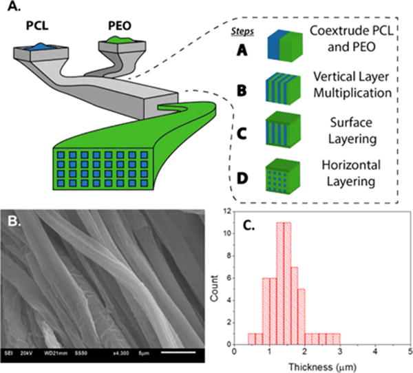
Coextrusion processing system. (A) Schematic for multilayered coextrusion of polymeric fibers. (B) Scanning electron micrograph of coextruded aligned PCL fibers. (C) Size distribution of fiber thickness. Mean value = 1.49 ± 0.48 μm.
Gradient Photochemistry
In this work, we sought to create a simple method to generate surface-immobilized chemical gradients on aligned extruded fibers. Owing to the ease with which photochemical modification occurs, we aimed to utilize a simple photomasking strategy to modulate the concentration of functionalized benzophenone deposited on the fibers. A 3 cm linear photomask was printed on transparency slides ranging from completely transparent to entirely black (Figure 2A), allowing us to modulate the UV-intensity for photochemistry by one full order of magnitude. PCL fibers were dip coated in a concentrated solution of propargyl benzophenone (Pr-Bz), allowed to dry, and subjected to UV-irradiation for 20 min (Scheme 1).
Figure 2.
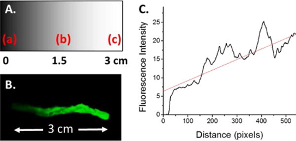
(A) Schematic of gradient photomask as inkjet printed onto transparency sheets: (a) is 100% black, (b) is 50% of black, and (c) is transparent as indicated in the text. (B) Fluorescence image of PCL-AF488 fiber gradient. (C) Plot of fluorescence intensity over the total fiber distance, indicating an approximate linear gradient of intensity.
Scheme 1.
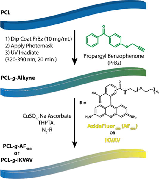
Synthetic Scheme To Generate PCL Fiber Gradients
Upon UV irradiation, Pr-Bz is excited to form a radical species, which can then undergo a radical insertion into the PCL backbone.30–32 This resulted in a new covalent bond between Pr-Bz and PCL, leaving surface exposed propargyl groups that could undergo the CuAAC reaction. After alkyne gradient formation, the CuAAC reaction was used to attach Azide Fluor 488 (AF488) to the fibers, a green fluorescent dye that allows for simple visualization of the gradient modified surface. The surface gradient was visualized using fluorescence imaging in the green channel, clearly indicating gradient formation (Figure 2B). The gradient intensity was analyzed by mean fluorescence intensity over the entire fiber bundle to correlate the fluorescent gradient to the linear photomask, showing a close-to-linear correlation to the mask (Figure 2C). This fibrous scaffold is processed as a thin layer and penetration depth of the UV irradiation and the subsequent click chemistry was at least 100 μM, as determined by confocal microscopy.28 As previously reported, there was no nonspecific adsorption of the dye molecules or the following peptides in the absence of the azide–alkyne pair and the corresponding copper catalysts.28
Quantification of AF488 Gradient
In order to quantify surface coverage following AF488 immobilization, dye coverage was quantified using UV–vis spectroscopy. Dye quantification proves to be much simpler than peptide quantification, due to the fact that protein concentration assays are performed under aqueous conditions. However, these fibers are not soluble in water or highly polar solvents that would be miscible with aqueous protein assays. In the past, dye quantification has correlated well to peptide conjugation. The correlation is likely due to the extreme efficiency of the ligand-accelerated CuAAC reaction and the bioorthogonality of the reaction. Rather than quantifying the gradient fibers directly, we chose to take individual points within the gradient and understand how UV fluence impacted surface coverage. Three individual photomasks were used to attach Pr-Bz, followed by CuAAC with AF488, where photomasks corresponded to (a), (b), and (c) in Figure 2A (i.e., completely transparent, 50% black, and 100% black) to evaluate surface coverage (Figure S1). After the CuAAC reaction, fibers were dissolved and dye loading was quantified and compared to BET surface area measurements (18.8 cm2/mg, Figure S3). The quantification of AF488 was determined using UV–vis spectroscopy at 501 nm against a standard curve in dichloromethane following dissolution of PCL-AF488 fibers. Fibers with a transparent photomask, corresponding to spot (c) (Figures 2A and S1), allowed UV transmittance of 28.6 mW/cm2 and led to 0.43 nM/cm2 of surface coverage (Figure S2) on the fiber bundle. An intermediate intensity, corresponding to 50% black in the photomask indicated by spot (b) (Figure 2A) provided 14.6 mW/cm2 of UV intensity. This photomask yielded 0.24 nM/cm2 of AF488 attachment onto the surface of the fibers (Figure S2). Finally, the UV intensity of the 100% black photomask (2.7 mW/cm2), corresponding to spot (a) (Figure 2A) of the gradient photomask yielded 0.09 nM/cm2 of AF488 decorated onto the fibers. Gratifyingly, the simple inkjet photomasking technique yielded approximate linear results that allowed us to tune the gradients by nearly an order of magnitude from 0.43 to 0.09 nM/cm2 onto the surface.
Gradient Surface Modification of PCL with IKVAV
It is well-known that cells can respond to haptotactic gradients, or surface immobilized gradients of biologically active molecules.19 Such gradients can lead to enhanced cell adhesion and migration relative to nongradient surfaces. In particular, neuronal cells are especially sensitive to these chemical perturbations and can undergo axonal elongation in the presence of haptotactic gradients of laminin-derived peptides, like IKVAV of YIGSR.20 We sought to employ this phenomenon with our extruded fibers, employing the same linear gradient as described above. An azide-modified IKVAV was synthesized and clicked onto Pr-Bz modified PCL fibers, using the optimized gradient conditions for photochemistry and ligand-accelerated CuAAC (PCL-g-IKVAV).33 As IKVAV does not provide the ease of quantification of the dye-immobilized molecules, several characterization techniques were carried out to investigate peptide gradient formation. First, PCL-g-IKVAV was analyzed by ATR-FTIR and FTIR imaging. The C=O stretching mode in the amide I region is coupled to the bending of the N–H bond and the stretching of the C–N bond represented between 1620 and 1640 cm−1. 34,35 The ATR-FTIR spectra at 1628 cm−1 confirmed an increasing amide I band (C=O) across the breadth of the fiber length of PCL-g-IKVAV with detection at the three different regions of the sample (Figure 3B). With increasing transparencies of the photomask, more intense amide I peaks are seen, indicating an increasing gradient of amide bonds, as would be expected for gradient IKVAV formation. FTIR imaging was also employed to visualize the spatial distribution of the C=O amide I band and is shown as a chemical heat map (Figure 3C) from spots (a) to (c) (scale bar on the right indicates intensity of absorbance, blue to red after normalization). The FTIR imaging result correlates well with the full ATR-FTIR spectra as an increase in the intensity of amide C=O bonds is seen, indicating an increase in concentration of IKVAV. Based on the IR micrographs, the resolution of the gradient is approximately 100 μm.
Figure 3.
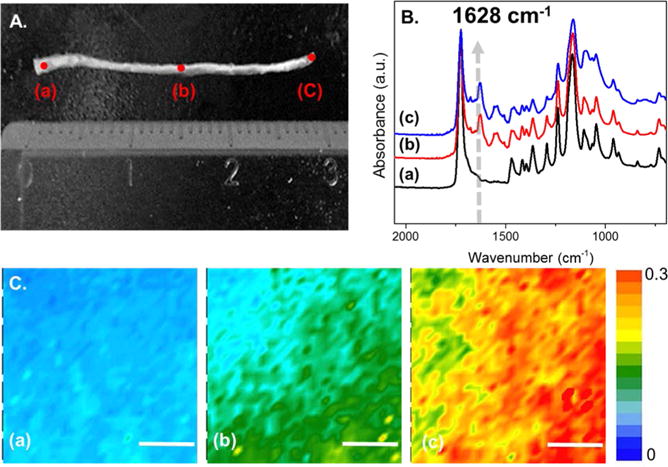
ATR-FTIR spectrum and IR imaging of the IKVAV PCL fiber gradient. (A) Digital image of PCL gradient-modified IKVAV fibers, indicating points where IR spectra were taken. (B) ATR-FTIR spectrum of varying spots on the PCL gradient (indicated in A). The arrow indicates the amide I region derived from the IKVAV peptide. (C) ATR-FTIR imaging at 1628 cm−1 (scale bar = 50 μm, intensity is indicated by a heat map as is indicated on the right).
Water contact angle provides an indication of the hydrophilicity and hydrophobicity on the surface of polymeric substrates. Cell adhesion also depends on the wettability of a scaffold surface, especially since synthetic biocompatible polymers, such as PCL, are hydrophobic, which usually limits cell interactions with the scaffold.36,37 Incorporating peptides such as IKVAV or YIGSR will likely improve the hydrophilicity of the surface, in addition to interacting with cell surface receptors, further enhancing the cell adhesion properties of the polymeric scaffold.38 Water contact angles were measured on PCL-g-IKVAV fibers from spot 1 to spot 4, indicating a decreasing water contact angle and, hence, an increasing amount of surface-immobilized IKVAV (Figure 4A). Water contact angle values decreased from 107.8 ± 7.5 to 65.5 ± 3.7° (Figure 4B), indicating that PCL-g-IKVAV fibers become more hydrophilic as surface density is increased. Furthermore, this follows a near linear trend as would be expected from our linear photomask. Therefore, it is likely that both gradient hydrophilicity and receptor specific interactions may play a role in improving cell surface adhesion.
Figure 4.
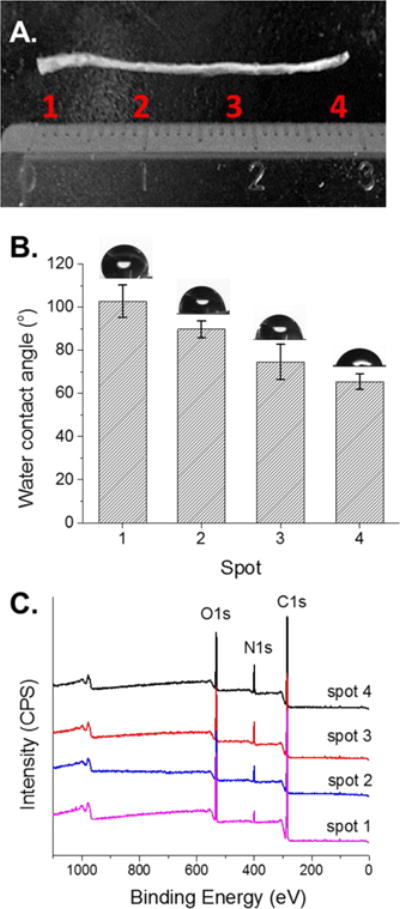
Surface characterization of PCL-g-IKVAV fibers. (A) Digital image of IKVAV gradient fibers, indicating spots taken for water contact angle and X-ray photoelectron spectroscopy. (B) Water contact angle (deg) of PCL-g-IKVAV fibers with four distinct spots from left (low peptide concentration) to right (high peptide concentration). Error bars represent standard deviation (n = 3). (C) Full XPS wide scan from left to right of PCL-gradient (spots 1–4), as indicated in (A). IKVAV fibers shows increasing intensity of nitrogen (N 1s) with increasing UV irradiation intensity.
Finally, PCL-g-IKVAV fibers were characterized by X-ray photoelectron spectroscopy (XPS) to determine nitrogen content, a unique atom after the fibers are peptide-modified. XPS wide scan of PCL-g-IKVAV fibers (Figure 4C) was performed at four distinct spots at increasing gradient densities, and the intensity of the N1s was quantified. An increasing intensity of N1s (relative %) at ~400 eV was seen, showing successful immobilization of gradiated amounts of IKVAV onto the PCL fibers. The percentages of nitrogen were 3.5, 7.5, 9.8, and 12.0% corresponding to spots 1–4 (Figure 4C) as a result of gradient IKVAV immobilization (see Table 1). In contrast, nongradient control fibers revealed 13.3% nitrogen, corresponding closely to the fully transparent photomask. By calculating the relative concentration of nitrogen, as compared to carbon and oxygen, we were able to determine peptide grafting density onto the fibers. Surface coverage is expressed as total peptide molecules per polymer chain and shows approximately 26, 83, 152, and 289 peptide modifications, respectively. This assumes that the molecular weight of PCL is narrowly distributed at 80 kg/mol (degree of polymerization ~ 700). The negative controls of PCL and PrBz-PCL fibers do not contain nitrogen, allowing for this calculation (Figure S6). This result also shows the linear behavior of the nitrogen to carbon ratio (N/C), confirming nearly linear gradient formation (Figure S5B). Based on this data and that represented by dye quantification experiments, it is anticipated that gradient density can be modified by at least 1 order of magnitude between low grafting density and high and that the upper limit of concentration can reach nearly 1 nmol/cm2. Clear differences in gradient density can be seen on the order of ~100 μm, as indicated by IR microscopy. Finally, as copper is a concern for biomedical applications the relative proportion of copper was determined by XPS and it was found that copper concentrations were consistent with complete copper removal (Figure S5A).
Table 1.
Surface Characterizationa
| sample | atomic component (%)
|
WCA angle (deg) | |||
|---|---|---|---|---|---|
| C (1s) | N (1s) | O (1s) | |||
| neat PCL | 74.6 | 25.4 | 112.3 ± 4.9 | ||
| PrBz-PCL | 74.4 | 25.6 | 95.1 ± 3.6 | ||
| PCL-ng-IKVAV | 70.7 | 16.0 | 13.3 | 62.3 ± 2.0 | |
| PCL-g-IKVAV | spot 1 | 77.9 | 3.5 | 18.6 | 107.8 ± 7.5 |
| spot 2 | 71.7 | 7.5 | 20.7 | 89.8 ± 3.9 | |
| spot 3 | 70.4 | 9.8 | 19.8 | 74.6 ± 8.1 | |
| spot 4 | 70.1 | 12.0 | 18.0 | 65.5 ± 3.7 | |
Neat PCL fibers, Pr-Bz-PCL, PCL-nongradient IKVAV fibers, and relative elemental concentrations of different spots on the PCL-g-IKVAV fibers (center, indicated in Figure 4) by XPS and values for water contact angles (right column).
In Vitro Characterization of Aligned PCL-g-IKVAV Fibers with PC-12 Cells
To determine the effects of the gradient on neural cells, growth of PC-12 cells was evaluated on three different substrates, unmodified PCL fibers, PCL nongradient IKVAV (PCL-ng-IKVAV), and PCL-g-IKVAV. PC-12 cells are derived from a pheochromocytoma of the rat adrenal medulla, which can differentiate into neurons and are commonly used as a model cell line in regenerative neural medicine. PC-12 cells were seeded onto the fiber and cultured for 5 days in the presence of nerve growth factor (NGF) to allow for neural differentiation and neurite extension. Following incubation, cells were fixed and stained using a NL557 conjugated anti β-III-tubulin antibody that is specific for neural differentiation (red) and DAPI for the nucleus (blue; Figure 5). Confocal microscopy images reveal different neurite extension and cellular density of PC-12 cells on each substrate, as well as in three different regions of each substrate. The density of cells on the unmodified PCL fibers, was significantly lower than that observed on the PCL-ng-IKVAV and PCL-g-IKVAV (Figure 5). Also, the three different areas on the unmodified PCL showed little adhesion, differentiation, and directed cell alignment (Figure 5A–C). In total, less than 50 cells were visualized throughout the total surface of the fibers, rendering it difficult to draw statistically significant conclusions. This would be expected, as PCL provides no biologically active cues, and the hydrophobic nature of the surface provides little adhesive capabilities for cells.
Figure 5.
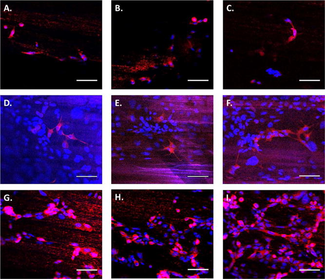
Confocal microscopy images of PC-12 cells. Cells were cultured for 5 days and stained with DAPI (blue) and anti-β-III-tubulin (red). Fiber orientation is approximately horizontal. (A–C) PC-12 cells cultured on unmodified PCL, corresponding to spots (a), (b), and (c) in Figure 3A, respectively. (D–F) PC-12 cells cultured on PCL-ng-IKVAV, which correspond to spots (a), (b), and (c) in Figure 3A. (G–I) PC-12 cells cultured on three different regions of PCL-g-IKVAV, which correspond to spots (a), (b), and (c) in Figure 3A, respectively. The direction of the gradient is left to right, where (G) is the lowest peptide concentration and (I) is the highest (scale bar = 50 μm).
The biologically active peptide, IKVAV, is known to bind to β-amyloid precursor protein and has been shown to promote adhesion and neurite outgrowth of PC-12 cells.39–41 It was postulated that PCL-ng-IKVAV would lead to improved adhesion but would have less propensity for cell alignment and extension than PCL-g-IKVAV fibers. Confocal images indicate a higher density of cells on nongradient substrates as higher IKVAV densities are seen throughout the nongradient fibers (Figure 5D–F). Although higher IKVAV densities enhanced cell adhesion on PCL-ng-IKVAV, there is minimal neuronal alignment or differentiation of PC-12 cells with a fixed concentration of IKVAV across the sample. Spreading of neurites was in arbitrary directions in the three different spots as observed via anti-β-III-tubulin, and neural differentiation was less significant when compared to gradient modified fibers. When nongradient substrates are compared to PCL-g-IKVAV, several differences arise. Figure 5G corresponds to the lowest concentration of IKVAV on the gradient and shows lower numbers of PC-12 cells, as compared to other regions on the same substrate. The highest cell density was seen on the highest concentrations of IKVAV on the gradient fibers (Figure 5I). In addition, PC-12 cells had noticeably elongated nuclei and neurites along the axis of the PCL-g-IKVAV fibers. The primary direction was along the gradient of the IKVAV motif, which showed the highest cell extension, differentiation and alignment of neurites, as compared to all other samples (Figure 5G–I). Regardless of peptide concentration on the gradient surface, neurite extension was seen both in the direction of the fibers and along the axis of the gradient. Cell alignment was further quantified by image analysis of nuclear elongation (Figure 6). The histogram of cell alignment shows the angular distribution of PC-12 cells relative to the fiber axis. The orientation of cells is, with respect to the fiber axis, represented as 0°. PCL-g-IKVAV clearly showed improved alignment relative to the nongradient substrates, with nuclear alignment averaging less than 30°. In contrast, nongradient samples showed a higher degree of randomness orienting throughout the angular window. These results imply that the gradient surface of PCL-g-IKVAV fibers is critical for strong biological activity and that the higher concentrations of IKVAV impacted cell adhesion. The gradient fibers affect differentiation of PC-12 cells and their alignment more so than solely the topographical cues of the aligned fiber direction.
Figure 6.

PC-12 orientation relative to the elongated axis of the fibers, where the fiber axis is represented as 0°. (A) Distribution of PC-12 cells on PCL-ng-IKVAV. (B) Distribution of PC-12 cells on PCL-g-IKVAV.
CONCLUSION
Photochemical gradient modification of a scalable class of melt coextruded fibers was presented and allowed for immobilization of azide-modified peptide gradients on the surface of aligned PCL fibers. Melt coextrusion allows for a significantly higher throughput of fiber production when compared to other common fiber processing techniques. In addition, we present a simple photochemical modification that is modular and allows for patterning of surface groups about the fiber. Gradient immobilization of the laminin-derived peptide, IKVAV, onto PCL fibers was easily accomplished. Gradient peptide concentrations and fiber alignment provide directional cues to neuronal cell growth, while future work will explore the interplay between fiber alignment and gradient compositions. We hope that these promising PCL-g-IKVAV fibers can improve axonal growth, promote cell adhesion, and provide directional cues to acute neuronal lesion tissues and trauma.
Supplementary Material
Acknowledgments
J.K.P. and R.C.A. acknowledge the National Science Foundation (NSF) Center for Layered Polymeric Systems for start-up funds (DMR 0423914) and generous use of the center’s confocal microscope. J.K.P. also acknowledges a NIH Pathway to Independence Award for funding (R00EB011530).
Footnotes
Supporting Information
Experimental details for peptide synthesis, BET measurements, and quantification of peptide gradients are included. This material is available free of charge via the Internet at http://pubs.acs.org.
Notes
The authors declare no competing financial interest.
References
- 1.Liu W, Thomopoulos S, Xia Y. Adv Healthc Mater. 2012;1:10–25. doi: 10.1002/adhm.201100021. [DOI] [PMC free article] [PubMed] [Google Scholar]
- 2.Khadka DB, Haynie DT. Nanomed Nanotechnol Biol Med. 2012;8:1242–1262. doi: 10.1016/j.nano.2012.02.013. [DOI] [PubMed] [Google Scholar]
- 3.Chew SY, Mi R, Hoke A, Leong KW. Adv Funct Mater. 2007;17:1288–1296. doi: 10.1002/adfm.200600441. [DOI] [PMC free article] [PubMed] [Google Scholar]
- 4.Sivolella S, Brunello G, Ferrarese N, Puppa AD, D’Avella D, Bressan E, Zavan B. Int J Mol Sci. 2014;15:3088–3117. doi: 10.3390/ijms15023088. [DOI] [PMC free article] [PubMed] [Google Scholar]
- 5.Martins A, Araújo JV, Reis RL, Neves NM. Nanomedicine. 2007;2:929–942. doi: 10.2217/17435889.2.6.929. [DOI] [PubMed] [Google Scholar]
- 6.Lutolf MP, Hubbell JA. Nat Biotechnol. 2005;23:47–55. doi: 10.1038/nbt1055. [DOI] [PubMed] [Google Scholar]
- 7.Sill TJ, von Recum HA. Biomaterials. 2008;29:1989–2006. doi: 10.1016/j.biomaterials.2008.01.011. [DOI] [PubMed] [Google Scholar]
- 8.Zheng J, Liu K, Reneker DH, Becker ML. J Am Chem Soc. 2012;134:17274–17277. doi: 10.1021/ja307647x. [DOI] [PubMed] [Google Scholar]
- 9.Zheng J, Xie S, Lin F, Hua G, Yu T, Reneker DH, Becker ML. Polym Chem. 2013;4:2215–2218. [Google Scholar]
- 10.Lancuški A, Fort S, Bossard F. ACS Appl Mater Interfaces. 2012;4:6499–6504. doi: 10.1021/am301458y. [DOI] [PubMed] [Google Scholar]
- 11.Smith Callahan LA, Xie S, Barker IA, Zheng J, Reneker DH, Dove AP, Becker ML. Biomaterials. 2013;34:9089–9095. doi: 10.1016/j.biomaterials.2013.08.028. [DOI] [PubMed] [Google Scholar]
- 12.Grodowska K, Parczewski A. Acta Polym Pharm. 2010;67:3–12. [PubMed] [Google Scholar]
- 13.Fatih Canbolat M, Tang C, Bernacki SH, Pourdeyhimi B, Khan S. Macromol Biosci. 2011;11:1346–1356. doi: 10.1002/mabi.201100108. [DOI] [PubMed] [Google Scholar]
- 14.Wu J, Mao Z, Tan H, Han L, Ren T, Gao C. Interface Focus. 2012;2:337–355. doi: 10.1098/rsfs.2011.0124. [DOI] [PMC free article] [PubMed] [Google Scholar]
- 15.Chelli B, Barbalinardo M, Valle F, Greco P, Bystrenova E, Bianchi M, Biscarini F. Interface Focus. 2014;4:20130041. doi: 10.1098/rsfs.2013.0041. [DOI] [PMC free article] [PubMed] [Google Scholar]
- 16.Mammadov B, Mammadov R, Guler MO, Tekinay AB. Acta Biomater. 2012;8:2077–2086. doi: 10.1016/j.actbio.2012.02.006. [DOI] [PubMed] [Google Scholar]
- 17.Hosseinkhani H, Hiraoka Y, Li C-H, Chen Y-R, Yu D-S, Hong P-D, Ou K-L. ACS Chem Neurosci. 2013;4:1229–1235. doi: 10.1021/cn400075h. [DOI] [PMC free article] [PubMed] [Google Scholar]
- 18.Yu TT, Shoichet MS. Biomaterials. 2005;26:1507–1514. doi: 10.1016/j.biomaterials.2004.05.012. [DOI] [PubMed] [Google Scholar]
- 19.Wrobel MR, Sundararaghavan HG. Tissue Eng, Part B. 2013 130812071112006. [Google Scholar]
- 20.Adams DN, Kao EY-C, Hypolite CL, Distefano MD, Hu W-S, Letourneau PC. J Neurobiol. 2005;62:134–147. doi: 10.1002/neu.20075. [DOI] [PubMed] [Google Scholar]
- 21.Mai J, Fok L, Gao H, Zhang X, Poo M. J Neurosci. 2009;29:7450–7458. doi: 10.1523/JNEUROSCI.1121-09.2009. [DOI] [PMC free article] [PubMed] [Google Scholar]
- 22.Yang F, Murugan R, Wang S, Ramakrishna S. Biomaterials. 2005;26:2603–2610. doi: 10.1016/j.biomaterials.2004.06.051. [DOI] [PubMed] [Google Scholar]
- 23.Hoffman-Kim D, Mitchel JA, Bellamkonda RV. Annu Rev Biomed Eng. 2010;12:203–231. doi: 10.1146/annurev-bioeng-070909-105351. [DOI] [PMC free article] [PubMed] [Google Scholar]
- 24.Wang J, Langhe D, Ponting M, Wnek GE, Korley LTJ, Baer E. Polymer. 2014;55:673–685. [Google Scholar]
- 25.Luo CJ, Stoyanov SD, Stride E, Pelan E, Edirisinghe M. Chem Soc Rev. 2012;41:4708–4735. doi: 10.1039/c2cs35083a. [DOI] [PubMed] [Google Scholar]
- 26.Persano L, Camposeo A, Tekmen C, Pisignano D. Macromol Mater Eng. 2013;298:504–520. [Google Scholar]
- 27.Repka MA, Shah S, Lu J, Maddineni S, Morott J, Patwardhan K, Mohammed NN. Expert Opin Drug Delivery. 2012;9:105–125. doi: 10.1517/17425247.2012.642365. [DOI] [PubMed] [Google Scholar]
- 28.Kim S-E, Wang J, Jordan AM, Korley LTJ, Baer E, Pokorski JK. ACS Macro Lett. 2014;3:585–589. doi: 10.1021/mz500112d. [DOI] [PMC free article] [PubMed] [Google Scholar]
- 29.Woodruff MA, Hutmacher DW. Prog Polym Sci. 2010;35:1217–1256. [Google Scholar]
- 30.Schneider MH, Tran Y, Tabeling P. Langmuir. 2011;27:1232–1240. doi: 10.1021/la103345k. [DOI] [PubMed] [Google Scholar]
- 31.Prucker O, Naumann CA, Rühe J, Knoll W, Frank CW. J Am Chem Soc. 1999;121:8766–8770. [Google Scholar]
- 32.Lancaster JR, Smilowitz R, Turro NJ, Koberstein JT. Photochem Photobiol. 2014;90:394–401. doi: 10.1111/php.12214. [DOI] [PubMed] [Google Scholar]
- 33.Hong V, Presolski S, Ma C, Finn MG. Angew Chem, Int Ed. 2009;48:9879–9883. doi: 10.1002/anie.200905087. [DOI] [PMC free article] [PubMed] [Google Scholar]
- 34.Yamada M, Kadoya Y, Kasai S, Kato K, Mochizuki M, Nishi N, Watanabe N, Kleinman HK, Yamada Y, Nomizu M. FEBS Lett. 2002;530:48–52. doi: 10.1016/s0014-5793(02)03393-8. [DOI] [PubMed] [Google Scholar]
- 35.Surewicz WK, Mantsch HH, Chapman D. Biochemistry (Moscow) 1993;32:389–394. doi: 10.1021/bi00053a001. [DOI] [PubMed] [Google Scholar]
- 36.Dhandayuthapani B, Yoshida Y, Maekawa T, Kumar DS. Int J Polym Sci. 2011;2011:e290602. [Google Scholar]
- 37.Mattanavee W, Suwantong O, Puthong S, Bunaprasert T, Hoven VP, Supaphol P. ACS Appl Mater Interfaces. 2009;1:1076–1085. doi: 10.1021/am900048t. [DOI] [PubMed] [Google Scholar]
- 38.Subramanian A, Krishnan UM, Sethuraman S. J Biomed Sci. 2009;16:108. doi: 10.1186/1423-0127-16-108. [DOI] [PMC free article] [PubMed] [Google Scholar]
- 39.Rice JJ, Martino MM, De Laporte L, Tortelli F, Briquez PS, Hubbell JA. Adv Healthc Mater. 2013;2:57–71. doi: 10.1002/adhm.201200197. [DOI] [PubMed] [Google Scholar]
- 40.Li Q, Chau Y. J Biomed Mater Res Part A. 2010;94A:688–699. doi: 10.1002/jbm.a.32707. [DOI] [PubMed] [Google Scholar]
- 41.Kibbey MC, Jucker M, Weeks BS, Neve RL, Nostrand WEV, Kleinman HK. Proc Natl Acad Sci USA. 1993;90:10150–10153. doi: 10.1073/pnas.90.21.10150. [DOI] [PMC free article] [PubMed] [Google Scholar]
Associated Data
This section collects any data citations, data availability statements, or supplementary materials included in this article.


