Abstract
The human body can act as a medium for the transmission of electromagnetic waves in the wireless body sensor networks context. However, there are transmission losses in biological tissues due to the presence of water and salts. This Letter focuses on lateral intra-body microwave communication through different biological tissue layers and demonstrates the effect of the tissue thicknesses by comparing signal coupling in the channel. For this work, the authors utilise the R-band frequencies since it overlaps the industrial, scientific and medical radio (ISM) band. The channel model in human tissues is proposed based on electromagnetic simulations, validated using equivalent phantom and ex-vivo measurements. The phantom and ex-vivo measurements are compared with simulation modelling. The results show that electromagnetic communication is feasible in the adipose tissue layer with a low attenuation of ∼2 dB per 20 mm for phantom measurements and 4 dB per 20 mm for ex-vivo measurements at 2 GHz. Since the dielectric losses of human adipose tissues are almost half of ex-vivo tissue, an attenuation of around 3 dB per 20 mm is expected. The results show that human adipose tissue can be used as an intra-body communication channel.
Keywords: electromagnetic wave transmission, body sensor networks, biological tissues, phantoms, dielectric losses
Keywords: electromagnetic wave transmission, wireless body sensor networks, transmission losses, water, salts, lateral intrabody microwave communication, biological tissue layers, tissue thicknesses, signal coupling, R-band frequencies, industrial radio band, scientific radio band, medical radio band, electromagnetic simulations, equivalent phantom, ex-vivo measurements, adipose tissue layer, phantom measurements, dielectric losses
1. Introduction
Wireless body sensor networks have recently attracted significant interest in a range of applications including medical and healthcare monitoring systems [1–3]. The human body has a complex anatomy comprising different layers of tissues such as skin, adipose (body fat), muscle and so on. The dielectric properties of these tissues depend on various factors such as the age, the body composition and the gender [4]. Moreover, the dielectric properties of a tissue can vary with the frequency, temperature and humidity. The dielectric properties of biological tissues can be roughly divided into two categories, based on their water contents. Tissues with high water content, such as muscles (73–78%) and skin (60–76%), and tissues with low water content, such as adipose (5–10%) and bone (8–16%) [5]. Adipose tissues are hydrophobic which means they retain less water and, consequently, have a low dielectric constant. Moreover, adipose tissues exhibit low dielectric losses compared with other tissues. Therefore, it is worthy to investigate the use of adipose tissues as a communication channel to transfer information through the human body.
From the statistic made by World Health Organization, more than 1.9 billion adults worldwide are overweight in 2014 and 31.58% of them are obese [6]. People suffering from obesity will have excess adipose deposition below the skin layer and in abdominal cavities. Obesity and overweight are often related to health problems such as diabetes, high blood pressure, respiratory ailments and so on [7]. These diseases require frequent follow-ups using implanted sensors [8]. A communication channel through the excess of adipose tissue will largely benefit in procuring physiological data from these patients.
Several studies in the literature were conducted to investigate normal signal transmission through multilayer tissues, such as capacitive [9, 10] and galvanic coupling [11–13], however little work has been done to investigate lateral signal transmission through a specific tissue. In this work, we investigate the lateral signal transmission in biological tissues and evaluate the use of these tissues as a communication channel for intra-body communication. To model the human biological tissues, we build two dielectric models that comprise three layers of tissue: skin, adipose and muscle. We do comprehensive parametric studies to investigate the impact of the tissues’ sizes on the transmission of electromagnetic waves.
This Letter demonstrates a new approach to characterise adipose and muscle tissue for intra-body communication channel over a microwave frequency range 1.7–2.6 GHz. These frequencies overlap with the industrial, scientific and medical radio (ISM) frequency band, which is free to be used in medical application. Microwave imaging applications also utilise similar frequencies such as 0.5–4 GHz [14]. Antennas working at these frequencies are used to communicate from implanted sensors to off body devices [15]. Referring to [16], in order to ensure the compatibly with other users, they use the unlicensed ultra-wideband spectrum for short-range patient monitoring and consume very low power.
To validate our results, we propose an experimental setup comprising of a realistic electromagnetic probe, an equivalent phantom for human tissues and ex-vivo tissues from pork belly.
This Letter is organised as follows. In Section 2, we briefly review the materials and techniques used in this work. Section 3 presents a theoretical study based on numerical simulations using the commercial CST microwave package. Section 4 briefly explains the electromagnetic probe we use in our simulations and experiment. Section 5 shows the comparison of dielectric properties of human tissues, phantom and ex-vivo. Section 6 describes the experimental setup and the results obtained by using equivalent phantom and ex-vivo tissues, and Section 7 shows the simulation setup. Results are presented and discussed in Section 8. Finally, concluding remarks are given.
2. Materials and methods
We investigate the wave propagation though human skin, adipose and muscle tissues at the frequency band 1.7–2.6 GHz. We study the effect of biological tissues thicknesses on the transmission channel. We choose two 3D models that we design separately using the commercial CST package. The two models, namely model A and model B, are shown in Figs. 1a and b. Model A is a three-layer structure comprising skin, adipose and muscle layers (organised from top to bottom, respectively), while model B contains the skin layer and a rather thick muscle layer (to represent low adipose body types). The two models have the dimensions 75 mm (W) × 75 mm (L), illustrated in Fig. 1, while the third dimension will vary. The dielectric properties of the tissues are given in Table 1 [17].
Fig. 1.

Simulation setup of models of the human tissues
a Model A: skin–adipose–muscle layer
b Model B: skin–muscle 1–muscle 2 layer
Table 1.
Dielectric properties of materials at 2.0 GHz [17]
| Tissues | Relative permittivity, εr | Conductivity, σ, S/m | Loss tangent, tan δ |
|---|---|---|---|
| skin | 38.57 | 1.27 | 0.30 |
| adipose | 5.33 | 0.09 | 0.15 |
| muscle | 53.29 | 1.46 | 0.25 |
Fig. 2 illustrates the proposed setup that we use to characterise the biological tissues. A transmitting probe (Tx) launches an electromagnetic signal that horizontally propagates towards the other side of the tissue, where a receiving probe (Rx) is used to detect the received signal. As a proof of concept, first we rely on the built-in waveguide ports, in the CST package, to simulate the electromagnetic probes Tx and Rx (later, we propose a realistic probe optimised to operate at the frequency band of interest). In addition, we use open-space boundary conditions around the setup to simulate non-reflecting environments. Further, we use the bio-tissue material included in the CST software to simulate the dielectric properties of the biological tissues.
Fig. 2.

Illustration of the model we use to characterise the biological tissues
3. Numerical investigations
Using the setup described in the previous section, we investigate the effect of the thickness of the layers, of the proposed models, on signal transmission. In all cases, the thickness of the skin layer is fixed to 2 mm. We investigate the impact of the thicknesses of the adipose and the muscle layers on signal transmission between Tx and Rx. Table 2 summarises the cases that we investigate. We used bio-tissue material included in the CST software to simulate three layers tissues behaviour depending on the thickness of each tissues.
Table 2.
Case studies used for investigating signal transmission in biological tissues
| Model | Thickness of tissue layer, mm | |
|---|---|---|
| Second layer | Third layer | |
| A | 10, 15, 20, 25, 30, 35 | 30 |
| 25 | 20, 25, 30, 35, 40, 45 | |
| B | 20, 25, 30, 35, 40, 45 | 30 |
First, we investigate the signal transmission through the adipose layer. We vary the thickness of the adipose layer from 10 to 35 mm, while keeping the thickness of skin and muscle tissues layer fixed. Fig. 3 compares S21 dB, as a function of frequency, obtained by simulation for various adipose layers. The simulation results show the signal coupling over the frequency band 1.7–2.6 GHz. We note that the amplitudes of the S21 dB improves as the thickness of the adipose layer increases until 25 mm and does not vary much when the thickness is increased further. This is because, for a given frequency range, a minimum dimension of waveguide is required to match the impedance. In this case, the three layers tissues can be considered as a waveguide filled with adipose. It can be seen from Fig. 3 that the best signal coupling occurs at 25 mm and above, and therefore it is considered as a good adipose thickness to be used for communicating in the given frequency range. The value of S21 for the thickest adipose layer is about −15 dB, which indicates a possible use of that tissue as a communication medium.
Fig. 3.
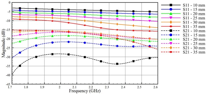
Impact of varying the adipose layer thickness on the coupled and reflected signals for model A (skin = 2 mm, adipose thickness varies from 10 to 35 mm, muscle thickness = 30 mm)
Second, we investigate the impact of the muscle layer thickness on signal transmission between Tx and Rx, when model A is used. We choose the 25 mm-thick adipose layer, which is also an average thickness for the adipose layer in human body [18]. We vary the thickness of the muscle tissue in model A from 20 to 45 mm. Fig. 4 shows that the muscle layer has a little impact on both the S21 and the S11 curves. The high contrast in the dielectric properties between the muscle and the adipose layer allows even thin muscle layers to act as good boundaries that confine signals within the adipose layer.
Fig. 4.
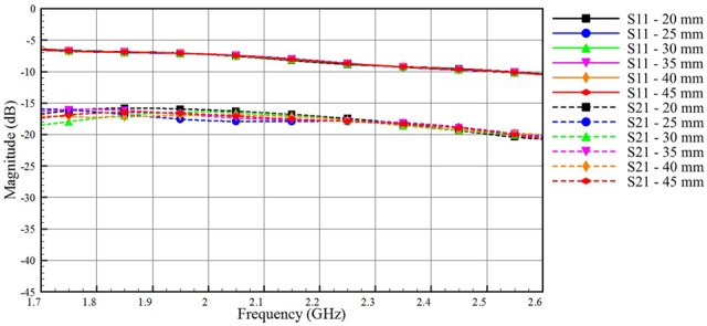
Impact of varying the thickness of the muscle layer on the coupled and reflected signals for model A (skin = 2 mm, adipose thickness = 25 mm, muscle thickness vary from 20 to 45 mm)
As a final study, we investigate the transmission of electromagnetic signals through the muscle layer. We use model B, where a muscle tissue that represents very low adipose body types replaces the adipose tissue of model A. Fig. 5 shows the reflection and the coupling coefficients through the muscle layer. Inspecting the scale of the vertical axis in Fig. 5, we see a very low signal coupling through the muscle layer, which is expected because of the high dielectric losses of this layer. We note that lower values of S11 (good matching between the port and the muscle layer) contribute to a better coupling through the muscle channel.
Fig. 5.
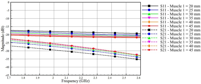
Impact of varying the thickness of the muscle layer of model B on the coupled and reflected signals (skin thickness = 2 mm, muscle 1 thickness varies from 20 to 45 mm, muscle 2 thickness = 30 mm)
Overall, the simulation results indicate that the adipose tissue can perform much better as a low loss communication channel than the muscle tissue. In the next section, we peruse an experimental characterisation of the adipose channel aiming to use this layer for intra-body communications.
4. Phantom and electromagnetic probe design
To validate our simulations, we propose an equivalent phantom model to represent the human tissues. Table 3 shows the materials that we use to construct the phantom together with their dielectric properties. We use the Agilent dielectric probe kit (Series number: 85070E) to measure the dielectric properties of these materials. By using computed tomography scanning, Hwang and Shin [19] gave reference values for the thickness of the adipose layer. In their study, they found that the adipose thickness varies from 3.5 mm (at biceps site) to 39.0 mm (at upper abdomen site), and the average adipose thickness in the upper part of the abdomen is around 22.2 mm. Therefore, we develop a phantom with 25 mm-thick adipose layer and we use 2 and 30 mm for the skin and the muscle layers, respectively. The equivalent phantom represents the skin, the adipose and the muscle. We use an agar-based material for the skin and the muscle, and for the adipose tissue we use adhesive putty.
Table 3.
Dielectric properties of the tissue-equivalent phantom at 2.0 GHz
| Tissues | Relative permittivity, εr | Conductivity, σ, S/m | ||
|---|---|---|---|---|
| Skin | 38.18 | 7.93 | ||
| adipose | rubber | adhesive putty | rubber | adhesive putty |
| 5.0 | 5.04 | 0.05 | 0.05 | |
| muscle | 56.11 | 11.28 | ||
We use an optimised probe that operates in the R-band (1.7–2.6 GHz). The probe shown in Fig. 6 consists of three parts: (i) A 25 mm × 50 mm × 70 mm rectangular waveguide section, (ii) a standard SubMiniature version A (SMA) connector and (iii) a topology optimised monopole antenna (TOMA) to match the SMA connector to the rectangular waveguide [20]. In order to ensure the electromagnetic continuity and maximise the signal coupling from the probe to the adipose layer, we fill the former with easily machinable rubber with dielectric properties similar to adipose. Table 3 shows the properties of the tissue-equivalent phantom at 2.0 GHz. The antenna is designed on a 0.762 mm-thick RO3203 substrate with relative permittivity 3.02, and a loss tangent of 0.016. The overall dimension of the antenna is 25 mm × 50.52 mm, while the overall dimension of the waveguide is 25 mm × 70 mm.
Fig. 6.
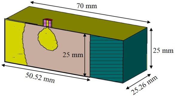
Probe to launch electromagnetic signals into the adipose layer (cross-sectional view)
Fig. 7 shows some steps of probe fabrication. A TOMA is designed and fabricated (Fig. 7a). The TOMA is inserted in a rubber block with a dimension of 70 mm × 50.52 mm × 25 mm as shown in Fig. 7b. The TOMA–rubber assembly is covered using copper tape to form a coax to waveguide adapter and the final probe is shown in Fig. 7c.
Fig. 7.
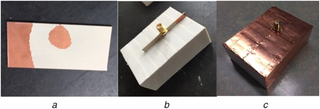
Prototype of the fabricated probe
a Topology optimised monopole antenna [20]
b Antenna immersed inside the rubber (adipose-equivalent material)
c Probe after final assembly
Fig. 8 shows the probe to probe measurement setup with Fieldfox Microwave Analyzer (N9918A). The probes are aligned horizontally and placed face to face in contact to measure S-parameters. The S-parameter measurement results for probe to probe configuration are shown in Fig. 9. Solid line shows the measurement results and the dashed line shows the simulation results. The resonant frequencies of both simulation and measurements are at 2.03 and 2.0 GHz with S11 of −24 and −23 dB, respectively. The measurement results agree with the simulation. Any discrepancy especially at 2.44 and 2.48 GHz might be due to uneven metallic surface (copper tape) of the probe. Since the probe offers better coupling at 2.0 GHz, it is considered as the centre frequency for result analysis. In this work, characterisation of the transmission channel is given more focus than optimising the probe itself.
Fig. 8.
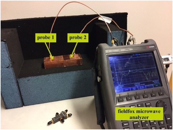
Probe to probe measurement
Fig. 9.
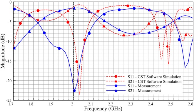
S-parameters of the probe to probe connection
5. Dielectric properties of phantom, ex-vivo and human tissues
Figs. 10–12 show the comparison of dielectric properties for skin, adipose and muscle with respect to the phantom, ex-vivo and human tissues at room temperature. The dielectric properties of the phantom, ex-vivo and human tissues are comparable.
Fig. 11.
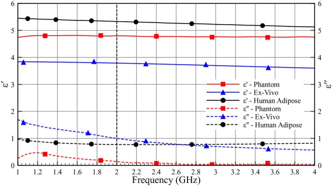
Dielectric properties (ɛ′ and ɛ″) of adipose as a function of frequency (1–4 GHz) at room temperature
Fig. 10.
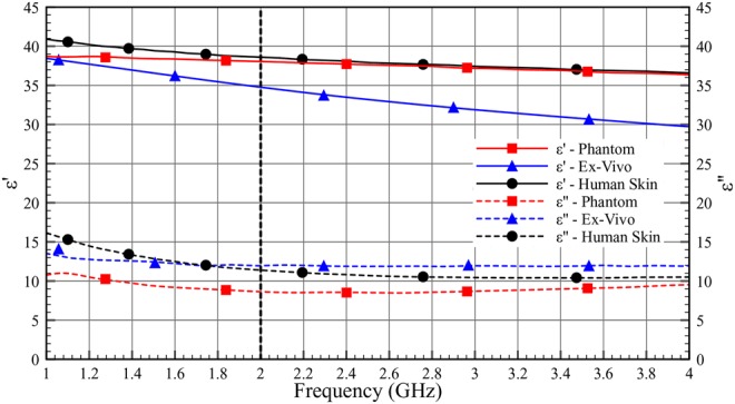
Dielectric properties (ɛ′ and ɛ″) of skin as a function of frequency (1–4 GHz) at room temperature
Fig. 12.
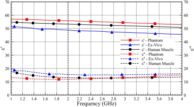
Dielectric properties (ɛ′ and ɛ″) of muscle as a function of frequency (1–4 GHz) at room temperature
Table 4 shows the permittivity and the loss tangent of the phantom, the ex-vivo and the human tissues. As can be seen in Table 4, the human tissue has lower losses compared with the ex-vivo measurement.
Table 4.
Comparison of dielectric properties (ε′ and tan δ) of the phantom, ex-vivo and human at 2.0 GHz
| Tissues | Phantom | Ex-vivo | Human | |||
|---|---|---|---|---|---|---|
| ε′ | tan δ | ε′ | tan δ | ε′ | tan δ | |
| skin | 38.182 | 0.208 | 34.839 | 0.343 | 38.570 | 0.295 |
| adipose | 5.038 | 0.010 | 4.096 | 0.202 | 5.328 | 0.145 |
| muscle | 56.114 | 0.201 | 48.855 | 0.317 | 53.290 | 0.245 |
6. Phantom and ex-vivo experimental setup
Fig. 13 shows the experimental setup that we use in our investigations. The three-layer equivalent phantom is placed between the two probes, which are aligned with the adipose layer. To investigate the signal transmission through the tissues, we study the scattering parameters (S11 and S21) of the two probes for a set of different tissue's lengths. We start by a length of 100 mm for the equivalent phantom and measure the scattering parameters of the two probes, and then we shorten the equivalent phantom by 10 mm after each measurement to perform the next one. We use a similar setup for the ex-vivo experiments as shown in Fig. 14a. In the ex-vivo experiments, we use pork belly meat comprising of skin, adipose and muscle. Moreover, to preserve the cuboid shape of the tissues, we use polystyrene holder to keep the muscle tissue in place as shown in Fig. 14b.
Fig. 13.
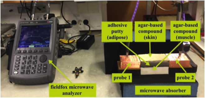
Experimental setup for phantom measurement
Fig. 14.
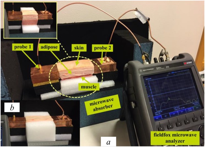
Experimental setup for ex-vivo
a Whole experimental setup
b Polystyrene holder to keep tissues in place
7. Simulation setup
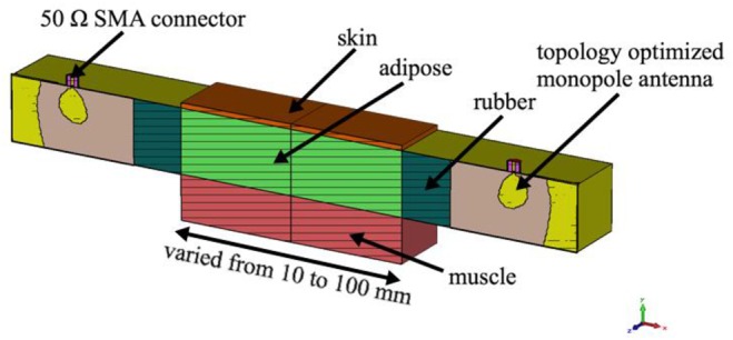
Fig. 15 shows the cross-sectional geometry of the simulation model in the CST software. The geometry consists of two probes and the three-layer tissue model. All measurement data for skin, adipose and muscle tissue were uploaded into the CST simulator, to obtain a similar environment in simulation as in the phantom and ex-vivo experimentation. We design and simulate the three-layer model and vary the distance between the two probes from 10 to 100 mm.
Fig. 15.
Cross-sectional view of the simulation model with R-band probe
8. Results and discussion
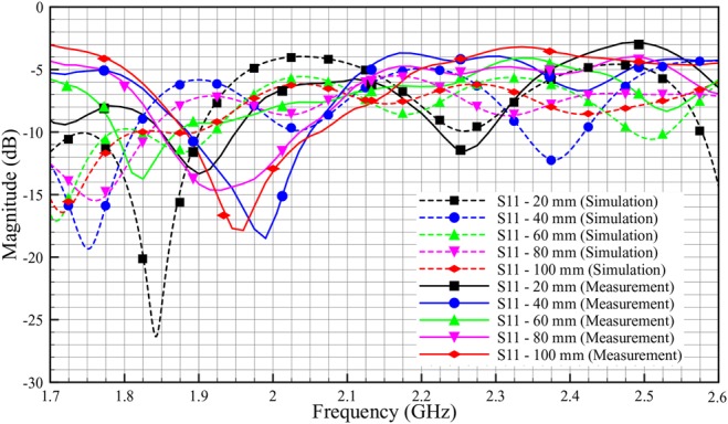
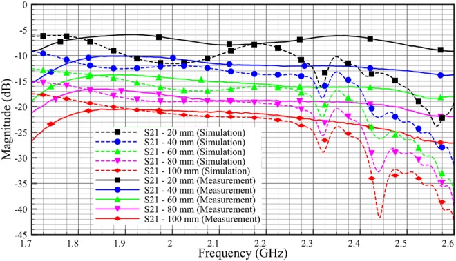
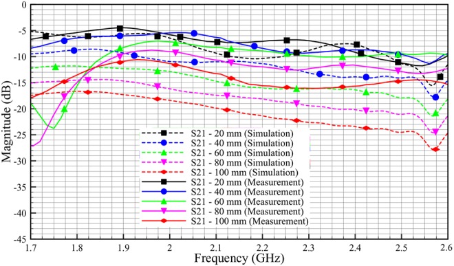
The S-parameter results for phantom and ex-vivo simulation and measurements are obtained and presented in this section. As shown in Figs. 16–19, the solid line corresponds to the measurement results, and the dashed line corresponds to the simulation results. The measurements and simulations were done by varying probe–adipose channel–probe, distance by 10 mm. For the brevity of the results, we have only provided the data with 20 mm variation.
Fig. 16.
Comparison reflection coefficient, S11 of phantom between simulation and measurement (skin = 2 mm, adipose = 25 mm, muscle = 30 mm)
Fig. 19.
Comparison transmission coefficient, S21 of ex-vivo between simulation and measurement (skin = 2 mm, adipose = 25 mm, muscle = 30 mm)
The rather large discrepancy shown in Fig. 16 between simulated and experimental values of S11 is not surprising. For a presumably matched system, also a small defect in the electromagnetic coupling will show up as a large difference since small values are compared. Possible explanations for the difference include geometrical distortions of the phantom setup and air bubbles getting stuck in the contact zone between the antenna patch and the adhesive putty.
The measurement results for phantom in Fig. 17 show a good signal coupling at R-band, which demonstrates that we can communicate through the adipose layer. The measurement results show good correlation with simulation results. For phantom of 100 mm length, we get an S21 value of −11 dB for measurement compared with −18 dB in simulation at 2 GHz. The discrepancy between simulation and measurement might stem from the difference in the shape of the physical phantom with the respect to simulation model. From Fig. 17, we also can see that, as the length of the phantom is decreased by 20 mm, the insertion loss (S21) is decreased by ∼2 dB, both for simulation and measurement.
Fig. 17.
Comparison transmission coefficient, S21 of phantom between simulation and measurement (skin = 2 mm, adipose = 25 mm, muscle = 30 mm)
Fig. 18 shows the discrepancy between simulated and experimental values of S11. It can be seen that, the discrepancies between simulation and measurement are much lesser compared with the phantom (Fig. 16). This is because, ex-vivo tissues retain better geometrical shape compared with that of phantom. As shown in Fig. 19, the S21 measurement results show good correlation with the simulation results. The graph shows a similar trend compared with the phantom experimentation. For ex-vivo of 100 mm length, the S21 value is almost −20.5 dB for measurement and −21.5 dB for simulation at 2 GHz. We also can see for both simulation and measurement, as the length of the ex-vivo is decreased by 20 mm, the insertion loss (S21) is decreased by ∼4 dB.
Fig. 18.
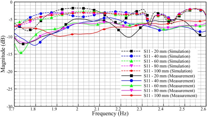
Comparison reflection coefficient, S11 of ex-vivo between simulation and measurement (skin = 2 mm, adipose = 25 mm, muscle = 30 mm)
In overall, we saw ∼2 dB per 20 mm loss in phantom measurement and 4 dB per 20 mm loss in ex-vivo measurement. The differences between phantom and ex-vivo measurements are due to the dielectric properties of loss tangent. Ex-vivo adipose tissue has high losses compared with phantom. Based on the loss tangent values for different adipose tissue in Table 4, we expect transmission characteristic with a loss of around 3 dB per 20 mm for human adipose tissue.
Variation in body composition has not been taken into account in this Letter. The results show that signal coupling is optimal in adipose tissue layers of 25 mm thickness and above and therefore the translation of our data to clinical application appears valid, as the mean thickness of adipose layers in the human body is 25 mm. Still, variation in body composition can be substantial and specifically in patients with a low body mass index the signal quality may be influenced by the thickness of the adipose layer.
This work will be beneficial in establishing communication between implanted sensors laterally over a wide area across human body. Using microwave signals for intra-body communication will substantially increase bandwidth and data rate. This communication methodology can offer higher integrity since the signals are confined between skin and muscle tissues. This work will also help in placing sensors deeper in the body (e.g. glucose sensors) down to muscle, and still be able to transmit and receive the signals even if the patient is obese. This will greatly improve lag time in glucose readings. Applications such as subcutaneous chemotherapy and drug delivery could also be benefitted from this work.
In the future work, we will consider different aspects of signal polarisation using smaller probes in both homogeneous and heterogeneous tissue models.
9. Conclusion
Different tissue types are characterised and analysed with respect to their dielectric and transmission properties. Three layered phantom and ex-vivo models consisting of skin, adipose and muscle tissues were simulated and measured at R-band to assess the intra-body microwave communication possibilities. The impact of various human adipose and muscle tissues thicknesses is studied in the CST simulation model. The signal transmission improves with the thickness of adipose and muscle tissues. The signal transmission is analysed with respect to the length of tissues channel. The results show that microwave transmission is possible through adipose tissue with a loss of ∼2 dB per 20 mm in phantom, and 4 dB per 20 mm in ex-vivo model. Since human adipose tissues have lower dielectric loss compared with ex-vivo tissues, the transmission loss can be calculated as about 3 dB. This work shows that the adipose tissue can offer low transmission loss for intra-body microwave communication. It can be a potential technique for monitoring disease conditions and transmitting information from or to implantable medical devices.
10. Funding and declaration of interests
This work was supported by Ministry of Higher Education, Malaysia, Universiti Teknikal Malaysia Melaka (UTeM), Eurostars project COMFORT (Grant E!9655-COMFORT), Swedish Vinnova project (Grant BDAS) and eSSENCE, a strategic collaborative eScience program funded by the Swedish Research Council. Conflict of interest: none declared.
11 References
- 1.Khaleghi A.A., Chavez-Santiago R., Balasingham I.: ‘Ultra-wideband statistical propagation channel model for implant sensors in the human chest’, IET Microw. Antennas Propag., 2011, 5, (15), pp. 1805–1812 (doi: 10.1049/iet-map.2010.0537) [Google Scholar]
- 2.Yazdandoost K.Y., Kohno R.: ‘Wireless communications for body implanted medical device’. 2007 Asia-Pacific Microwave Conf., Bangkok, 2007, pp. 1–4 [Google Scholar]
- 3.Kaka A.O., Toycan M.: ‘Dual band implant antenna design with miniaturized and biocompatible characteristics for wireless health monitoring’. 2016 24th Signal Processing and Communication Application Conf. (SIU), Zonguldak, 2016, pp. 1725–1728 [Google Scholar]
- 4.Da Graça Lopes C.A.: ‘Characterisation of the radio channel in on-body communications’. MS thesis, Universidade Técnica de Lisboa, Lisboa, Portugal, 2010 [Google Scholar]
- 5.Komarov V., Wang S., Tang J.: ‘Permittivity and measurements’. In Chang K. (Ed.): ‘Encyclopedia of RF and microwave engineering (3693e3711)’, (John Wiley and Sons, Inc, New York, 2005) [Google Scholar]
- 6.2016 Obesity and overweight Fact sheet, World Health Organization. Available at www.who.int/mediacentre/factsheets/fs311/en/ , accessed November.
- 7.U.S. Department of Health and Human Services, National Institute of Diabetes and Digestive and Kidney Diseases: ‘Do you know some of the health Risks of being overweight?’. Available at https://www.niddk.nih.gov/health-information/health-topics/weight-control/health_risks_being_overweight/Documents/hlthrisks1104.pdf. Updated December 2012, accessed November 2016
- 8.Lucisano J., Routh T., Lin J., et al. : ‘Glucose monitoring in individuals with diabetes using a long-term implanted sensor/telemetry system and model’, IEEE Trans. Biomed. Eng., doi: 10.1109/TBME.2016.2619333 [DOI] [PMC free article] [PubMed] [Google Scholar]
- 9.Zhao K., Ying Z., He S.: ‘Intra-body communications between mobile device and wearable device at 26 MHz’, IEEE Antennas Wirel. Propag. Lett., 2017, 16, pp. 549–552 (doi: 10.1109/LAWP.2016.2588524) [Google Scholar]
- 10.Kazim M.I., Kazim M.I., Wikner J.J.: ‘Realistic path loss estimation for capacitive body-coupled communication’. European Conf. on Circuit Theory and Design (ECCTD), 2015, Trondheim, 2015, pp. 1–4 [Google Scholar]
- 11.Swaminathan M., Muncuk U., Chowdhury K.R.: ‘Tissue safety analysis and duty cycle planning for galvanic coupled intra-body communication’. 2016 IEEE Int. Conf. on Communications (ICC), Kuala Lumpur, 2016, pp. 1–6 [Google Scholar]
- 12.Swaminathan M., Muncuk U., Chowdhury K.R.: ‘Topology optimization for galvanic coupled wireless intra-body communication’. IEEE INFOCOM 2016 – The 35th Annual IEEE Int. Conf. on Computer Communications, San Francisco, CA, 2016, pp. 1–9 [Google Scholar]
- 13.Wegmueller M.S., Oberle M., Felber N., et al. : ‘Galvanical coupling for data transmission through the human body’. 2006 IEEE Instrumentation and Measurement Technology Conf. Proc., Sorrento, 2006, pp. 1686–1689 [Google Scholar]
- 14.Ruvio G., Cuccaro A., Solimene R., et al. : ‘Microwave bone imaging: a preliminary scanning system for proof-of-concept’, Healthc. Technol. Lett., 2016, 3, (3), pp. 218–221, (doi: 10.1049/htl.2016.0003) [DOI] [PMC free article] [PubMed] [Google Scholar]
- 15.Kim A.J., Rahmat-Samii Y.: ‘Implanted antennas inside a human body: simulations, designs, and characterizations’, IEEE Trans. Microw. Theory Tech., 2004, 52, (8), pp. 1934–1943 (doi: 10.1109/TMTT.2004.832018) [Google Scholar]
- 16.2016 Fish and Richardson Regulatory (2013) Wireless medical technologies: navigating government regulation in the new medical age. Fish's Regulatory & Government Affairs Group. Available at http://www.fr.com/files/Uploads/attachments/FinalRegulatoryWhitePaperWirelessMedicalTechnologies.pdf , accessed November.
- 17.2016 IFAC, Dielectric properties of body tissues calculator. Available at http://niremf.ifac.cnr.it/tissprop/ , accessed November.
- 18.Kim C.W., See T.S.P.: ‘RF transmission power loss variation with abdominal tissues thicknesses for ingestible source’. 13th IEEE Int. Conf. e-Health Networking Applications and Services (Healthcom), 2011, Columbia, MO, 2011, pp. 282–287 [Google Scholar]
- 19.Hwang I.D., Shin K.: ‘Fat thickness measurement using optical technique with miniaturized chip LEDs: a preliminary human study’. 2007 29th Annual Int. Conf. of the IEEE Engineering in Medicine and Biology Society, Lyon, 2007, pp. 4548–4551 [DOI] [PubMed] [Google Scholar]
- 20.Hassan E.: ‘Topology optimization of antennas and waveguide transitions’. PhD thesis, Department of Computing Science, Umeå University, 2015 [Google Scholar]


