Abstract
Light–matter strong coupling allows for the possibility of entangling the wave functions of different molecules through the light field. We hereby present direct evidence of non‐radiative energy transfer well beyond the Förster limit for spatially separated donor and acceptor cyanine dyes strongly coupled to a cavity. The transient dynamics and the static spectra show an energy transfer efficiency approaching 37 % for donor–acceptor distances ≥100 nm. In such systems, the energy transfer process becomes independent of distance as long as the coupling strength is maintained. This is consistent with the entangled and delocalized nature of the polaritonic states.
Keywords: cyanine dyes, non-radiative energy transfer, quantum entanglement, strong coupling
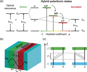
Energy transfer is a ubiquitous phenomenon in nature and the underlying non‐radiative process has been extensively studied over the years and typically relates either short‐range dipole–dipole interactions (Förster) or electronic exchange (Dexter).1 Many factors can affect these types of energy transfer such as the local photonic mode density1, 2, 3, 4, 5, 6 which can be controlled in the weak light–matter interaction regime. This is typically achieved by placing the quantum emitters in a resonant cavity. Another way to modify energy transfer is under strong light–matter coupling as recently demonstrated.7, 8 In those experiments, both the donor D and the acceptor A were coupled to a cavity, leading to a cascade of hybrid light–matter or polaritonic states as illustrated in Figure 1 a. The three new hybrid states, namely the upper (UP), middle (MP) and lower (LP) polaritonic states are quantum mechanically entangled and provide an effective path for energy transfer. This is very much like when the donor and acceptor are chemically linked with an overlap of their wave functions.7 We reported that the rate of non‐radiative energy transfer was increased by a factor of seven under those conditions as compared to the normal situation outside the cavity, with a corresponding effect on the energy transfer efficiency.7 Such cascaded strongly coupled systems lead to the intriguing possibility of achieving energy transfer of spatially separated but entangled donors and acceptors over distances where Förster type mechanism is no longer possible as illustrated in Figure 1 b. It should be recalled that Förster type energy transfer rate k ET is proportional to where R DA is the average donor–acceptor distance and it is well established that energy transfer is highly unlikely for R DA≥10 nm. Herein, we present direct evidence for non‐radiative energy transfer of spatially separated but entangled molecules well beyond this Förster limit. This is observed from both static measurements and the transient dynamics and interestingly the energy transfer becomes independent of distance as long as the strong coupling strength is constant. Such findings add to a rich variety of quantum phenomena that can be observed by using hybrid light–matter states such as coherent emission9, 10 and room temperature polariton condensation11, 12 in addition to modifications of chemical and material properties in strongly coupled organic materials.13, 14, 15, 16, 17, 18, 19, 20, 21, 22
Figure 1.

a) Schematic representation of cascade strong coupling successively with the donor resonant with a cavity modem , and then the acceptor, leading to the formation of three new eigen hybrid light–matter states: the upper (UP), middle (MP), and lower (LP), polaritonic states. b) Schematic diagram of the strongly coupled Fabry–Pérot cavity with spatial separated donor and acceptor. The spacer thickness h can be tuned from 10 nm to 75 nm. c) Temporal picture of the dipole allowed energy transfer processes from an initial state where D is excited and A is in the ground state, to a final state where A is excited and D is in the ground state. Those processes involve an intermediate state in which a cavity photon of frequency , wavevector and polarization, is exchanged.
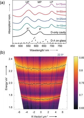
For the purpose of this study, we used the same J‐aggregates of two cyanine dyes, TDBC as D, and BRK as A (see General method in the Supporting Information, SI) as we did in our previous work7 because they have all the required spectroscopic features. To build the hybrid light–matter states with TDBC and BRK as illustrated in Figure 2 a, an optical cavity mode is first chosen to be resonant with the D absorption maximum at 590 nm (2.1 eV). The absorption spectrum of the system (donor plus resonant cavity) is then modified by strong coupling leading to the formation of two new hybrid light–matter eigen states (P+ and P−).20 As a consequence, new absorption peaks appear corresponding to P+ at 548 nm (2.26 eV) and P− at 640 nm (1.94 eV), separated in this case by a vacuum Rabi splitting of 320 meV, as shown in Figure 1 a (black curve). The transition energy to P− is in turn close to BRK J‐aggregate absorption maximum at 659 nm (1.88 eV) enabling them couple and finally leading to the three hybrid polaritonic eigenstates UP, MP and LP, illustrated in Figure 1 a and shown experimentally in Figure 2 a for different polymer spacer layers. As discussed in the introduction, a crucial factor for Förster type energy transfer is the average D–A distance. We recall that the Förster type energy transfer rate constant can be written as , where η represents contributions such as concentration and refractive index, κ 2 is the relative orientation factor of D and A transition dipole moments, κ D is the donor decay rate and J is the spectral overlap integral calculated from the D emission and the A absorption spectra. To explore the energy transfer between spatially separated but entangled D and A, we added a polymer spacer between D and A layers (Figure 1 b). Figure 2 a shows the absorption spectra of the strongly coupled system with different poly (methyl methacrylate) (PMMA) spacer thicknesses h between 10 nm and 75 nm. The corresponding transmission (T) and reflection (R) spectra are shown in the SI (Figure S1). Atomic force microscopy (AFM) was used to study the surface profile of each separated PMMA layer to ensure that they were flat across the sample. It can be seen that increasing the PMMA thickness hardly changes the energies of the hybrid polariton absorption bands as expected since we use the second mode of the FP cavity (Figure 1 b) so that D and A are located at the anti‐nodes where strong coupling is most favourable (we recall that the Rabi splitting , where d is the transition dipole moment and E is the electric field17, 20). At the same time the spacer is centered at the node where E is weakest.
Figure 2.

a) Normalized absorption spectra for various spacer thickness (10 nm to 75 nm) of donor (TDBC) and acceptor (BRK) in the strongly coupled cavity. The absorption A is determined after recording the transmission T and the reflection R of the samples (A=1−T−R). The black dash curve shows the spatial separated donor and acceptor absorbance spectrum on top of a glass substrate. b) Example of the reflection dispersion plots in the donor–acceptor (h=50 nm) strongly coupled cavity. The white lines correspond to the coupled oscillator model results with different Hopfield coefficient. The blue line indicates the angle (22.5°) where the excitation spectra were collected.
Example of reflection dispersion of the polaritonic states for h=50 nm is shown in Figure 2 b. This dispersive behaviour which is due to photonic content of the polaritonic states can be simulated by a three‐coupled oscillator model consisting of the optical cavity7, 8 mode and the two excitonic transitions of D and A (see the SI). As can be seen in Figure 2 b, the simulation is in exact agreement with the experimental data. From the same analysis, we can also estimate the mixing coefficients , and describing the photonic, D and A excitonic content of the polaritonic states (Hopfield coefficients). For h=50 nm sample and at resonance (k=0), the D/A ratios for UP, MP and LP are, respectively 11.6, 1.2 and 0.1. In other words, the energy should flow from the mostly donor like UP to mostly acceptor like LP just like energy transfer in chemically linked D–A systems.
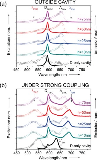
Next we study the emission and excitation spectra of the D–A system under strong coupling and compare them with those outside the cavity for different spacer thicknesses h. When only the donor is strongly coupled, the emission is already modified in the cavity (black curves). The TDBC fluorescence spectrum at 590 nm is broadened by the new emission at 640 nm from P−. The co‐existence of both emissions is well understood and it is due to the fact that not all molecules are coupled to the cavity because of their orientation and position relative to the optical field.17, 20
When both D and A are strongly coupled, the emission is totally changed as can be seen by comparing Figures 3 a and b. Outside the cavity (Figure 3 a), the emission spectra are dominated by D (TDBC) peak, the tiny emission signal from A at 660 nm is due to some direct excitation at 530 nm as there is no energy transfer, as expected for such large distances between D and A. Under strong coupling however, the emission spectra for all spacer thicknesses are dominated by two peaks which correspond to the LP emission and uncoupled D. The LP emission indicates that energy transfer is occurring under strong coupling via the entangled D and A molecules. An example of the dispersion curves of the emission spectra for D–A inside the cavity is shown in SI (Figure S2).
Figure 3.

Normalized excitation (dots) and emission (solid line) spectra from varying spacer thickness from 10 nm to 75 nm. a) in the absence of the top Ag mirror (outside cavity) and b) in the strongly coupled system. The emission spectra are recorded upon excitation at 530 nm with normal measurement while the excitation spectra are collected at 700 nm at an angle of 22.5°.
To confirm that energy transfer is indeed occurring in these coupled systems, the excitation spectra were recorded at 700 nm. Outside the cavity, the excitation spectra (Figure 3 a) is dominated by the absorption of A (BRK). A small contribution at the D (TDBC) absorption is due to the fact that D also emits weakly at 700 nm as confirmed by the excitation spectrum for D only (black circles in Figure 3 a). When both D and A are strongly coupled, the excitation spectra exhibit 3 peaks corresponding to UP, MP and LP which in agreement with the absorption peaks of the coupled systems shown in Figure 1 a.
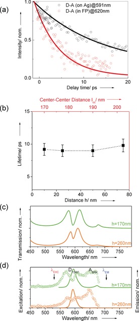
These static measurements show that energy transfer is indeed mediated by the hybrid polaritonic states of the entangled D and A across the spacer layer. As a final confirmation of the long‐distance non‐radiative energy transfer under these conditions, the dynamics of the system was also studied by femtosecond pump–probe spectroscopy (transient spectra are shown in the SI Figure S3). The donor lifetime is ca. 15 ps whether outside or inside the cavity in the absence of strong coupling (see the SI). In samples consisting of D, A and spacer layers (i.e. prepared in the same way as under strong coupling conditions) but without the cavity, D lifetime remains unchanged indicating in agreement with the static measurements that no energy transfer happens outside cavity at these spacer thicknesses as expected from Förster theory.23 This is shown in Figure 4 a where the decay dynamics of D–A system outside the cavity (black circles) are compared with the strongly coupled system (red circles). As can be seen, in the latter case, the decay dynamics is shortened to τ DA=9 ps as observed by monitoring the spectral region corresponding to the middle polariton MP which is the intermediate state through which the energy transfer occurs (Figure 1 a). The UP is so short lived that we cannot detect with our 150 fs resolution. From these values, the energy transfer rates R ET=k ET[A] can be extracted since R ET=1/τ DA−1/τ D and in the strongly coupled system the rate is 0.04×10¹² s−1 under these experimental conditions. The competition between the decay of the donor and energy transfer dynamics is in quantitative agreement with the ratios of the emission peaks corresponding to the donor and LP of Figure 3 b as discussed below.
Figure 4.

a) The decay kinetics of the donor‐acceptor (h=50 nm) outside cavity at the TDBC absorption maximum 591 nm (black circles), and of MP in the strongly coupled system at 620 nm (red circles). b) The lifetimes of MP recorded at different spacer thickness for the strongly coupled donor–acceptor cavity. c) Normalized transmission spectrum of cavities with spacer thicknesses h=170 and 260 nm. d) Normalized excitation (dots) and emission (solid line) spectra as in Figure 3.
When we modify the spacer thickness from 10 nm to 75 nm we are able to maintain the strong coupling strength nearly constant (see Figure 2 a) because D and A are then centered at the anti‐nodes as discussed earlier. Interestingly, the dynamics do not change as shown in Figure 4 b, which in agreement with the static experiments in Figure 3 where the energy transfer efficiency is invariant. What's more, if one considers the center to center distance between D and A layers as shown in Figure 1 a (lCC) and Figure 4 b (top red scale), the distance is on average much longer. As discussed further down, our theoretical model predicts that the energy transfer will drop with the coupling strength ħΩR. We first checked this by detuning the cavity away from strong coupling. Indeed, energy transfer disappears and the D lifetime is recovered (see the SI). In a second check, the concentrations of D and A were reduced to decrease the coupling strength (it depends on the square root of the coupled molecules in the mode volume)20 and the energy transfer decreases correspondingly (see Figure S5 in the SI) but here one is limited by the fact that J‐aggregates de‐aggregate as their concentration is reduced. Therefore, to analyse further the effect of the coupling strength, the spacer thickness was increased all the while keeping the cavity length and mode constant, and reducing the thickness of the D and A layers. In Figure 4 c and d shows the case for two spacer thicknesses. At h=170 nm, there is still some strong coupling (130 meV splitting between UP and MP) but the emission form the LP is severely reduced. For h=260 nm, no emission is detected at the wavelength corresponding to A or LP which is not surprising since the system is no longer meets the strong coupling criteria, that is, the peak splitting (75 meV) is smaller than the width of the optical mode (85 meV). Thus entanglement via strong coupling is clearly essential for energy transfer over such large distances. Weak coupling effects on D–A energy transfer inside resonant cavities occur over distance less than ca. 20 nm.2
The energy transfer efficiency can be written as:
| (1) |
where and are the radiative and non‐radiative decay rate constants of the donor state. From this equation and the data, we estimate . Compared with the former study,7 this energy transfer efficiency is lower than the homogenously mixed donor–acceptor case (ca. 0.90). This is reasonable since in the latter system, there are two channels contributing to the energy transfer process. One is the short‐range dipole–dipole interaction while the other involves the entangled hybrid states.
In this spatially separated system, the short‐range dipole–dipole interaction between D and A is obviously supressed by the spacer. Therefore, to place these results in the context of Förster theory, we need only to consider the long range interactions involving the quantized photonic mode of the cavity, which is the one participating in the strong coupling (Figure 1 c). As detailed in SI, this single mode restriction modifies the usual Förster energy transfer rate.24, 25 In particular, the ET probability amplitude only depends on the light–matter coupling strength at the D and A positions in the field of the cavity and no longer on the distance:
| (2) |
where d A(D) is the transition dipole moment of A (D) molecule, is the energy of the cavity mode, V its mode volume, the polarization unit vector of A (D, cavity mode), the electric field amplitude at A (D) position in the cavity, and * stands for the complex conjugate. The net ET rate from a given D to a collection of A is then proportional, on the basis of Fermi's golden rule, to , where the position of the A is summed over the acceptor layer. In other words, the energy is carried from the D to A via two successive Rabi oscillations corresponding to the collective dressing of both D and A by the cavity. This implies that the energy transfer will collapse in this regime with the square of the light–matter coupling strength (see the SI) as found experimentally and reported above. A striking implication of this result is that, as long as one maintains the same coupling strength, the energy transfer process remains distance‐independent (i.e. Figure 3 b). Our results are also in agreement with a recent theoretical study that has come to our attention which shows that energy transfer can occur very efficiently between spatially distant points in excitonic‐plasmonic structures with the onset of strong coupling.26
Clearly the energy transfer process described here belongs neither to the Förster (short‐range dipole–dipole interaction) or the Dexter (electronic wave‐function overlap) type mechanisms. It has become independent of distance due to the entangled and delocalized nature of the hybrid polaritonic states. This is in line with theoretical studies on exciton transport in polaritonic systems,14,15, 26 and the observation of enhanced electronic transport in organic semiconductors under strong coupling.13 Interestingly, there is also evidence that quantum coherence plays a role in photosynthetic light harvesting systems, thus modifying the traditional incoherent picture of energy transfer.27, 28
The present demonstration of efficient energy transfer between entangled spatially separated D–A systems shows that strong coupling provides a relatively simple platform to investigate chemical and molecular phenomena under quantum entanglement. The additional freedom provided by the entanglement to separate donors and acceptors could also be used to improve the design of solar energy conversion systems. Light–matter strong coupling thus opens the way to bring quantum features into molecular and material science with rich consequences.
Conflict of interest
The authors declare no conflict of interest.
Supporting information
As a service to our authors and readers, this journal provides supporting information supplied by the authors. Such materials are peer reviewed and may be re‐organized for online delivery, but are not copy‐edited or typeset. Technical support issues arising from supporting information (other than missing files) should be addressed to the authors.
Supplementary
Acknowledgements
We acknowledge support of the International Center for Frontier Research in Chemistry (icFRC, Strasbourg), the ANR Equipex Union (ANR‐10‐EQPX‐52‐01), the Labex NIE projects (ANR‐11‐LABX‐0058 NIE) and CSC (ANR‐10‐LABX‐ 0026 CSC) within the Investissement d'Avenir program ANR‐10‐IDEX‐0002‐02.
X. Zhong, T. Chervy, L. Zhang, A. Thomas, J. George, C. Genet, J. A. Hutchison, T. W. Ebbesen, Angew. Chem. Int. Ed. 2017, 56, 9034.
References
- 1. Scholes G. D., Annu. Rev. Phys. Chem. 2003, 54, 57–87. [DOI] [PubMed] [Google Scholar]
- 2. Andrew P., Barnes W. L., Science 2000, 290, 785–788. [DOI] [PubMed] [Google Scholar]
- 3. Götzinger S., Menezes L. de S., Mazzei A., Kühn S., Sandoghdar V., Benson O., Nano Lett. 2006, 6, 1151–1154. [DOI] [PubMed] [Google Scholar]
- 4. Konrad A., Metzger M., Kern A. M., Brecht M., Meixner A. J., Nanoscale 2015, 7, 10204–10209. [DOI] [PubMed] [Google Scholar]
- 5. Blum C., Zijlstra N., Lagendijk A., Wubs M., Mosk A. P., Subramaniam V., Vos W. L., Phys. Rev. Lett. 2012, 109, 203601. [DOI] [PubMed] [Google Scholar]
- 6. Ghenuche P., de Torres J., Moparthi S. B., Grigoriev V., Wenger J., Nano Lett. 2014, 14, 4707–4714. [DOI] [PubMed] [Google Scholar]
- 7. Zhong X., Chervy T., Wang S., George J., Thomas A., Hutchison J. A., Devaux E., Genet C., Ebbesen T. W., Angew. Chem. Int. Ed. 2016, 55, 6202–6206; [DOI] [PubMed] [Google Scholar]; Angew. Chem. 2016, 128, 6310–6314. [Google Scholar]
- 8. Coles D. M., Somaschi N., Michetti P., Clark C., Lagoudakis P. G., Savvidis P. G., Lidzey D. G., Nat. Mater. 2014, 13, 712–719. [DOI] [PubMed] [Google Scholar]
- 9. Aberra Guebrou S., Symonds C., Homeyer E., Plenet J. C., Gartstein Y. N., Agranovich V. M., Bellessa J., Phys. Rev. Lett. 2012, 108, 066401. [DOI] [PubMed] [Google Scholar]
- 10. Shi L., Hakala T. K., Rekola H. T., Martikainen J.-P., Moerland R. J., Törmä P., Phys. Rev. Lett. 2014, 112, 153002. [DOI] [PubMed] [Google Scholar]
- 11. Plumhof J. D., Stöferle T., Mai L., Scherf U., Mahrt R. F., Nat. Mater. 2013, 13, 247–252. [DOI] [PubMed] [Google Scholar]
- 12. Daskalakis K. S., Maier S. A., Murray R., Kéna-Cohen S., Nat. Mater. 2014, 13, 271–278. [DOI] [PubMed] [Google Scholar]
- 13. Orgiu E., George J., Hutchison J. A., Devaux E., Dayen J. F., Doudin B., Stellacci F., Genet C., Schachenmayer J., Genes C., Pupillo G., Samorì P., Ebbesen T. W., Nat. Mater. 2015, 14, 1123–1129. [DOI] [PubMed] [Google Scholar]
- 14. Feist J., Garcia-Vidal F. J., Phys. Rev. Lett. 2015, 114, 196402. [DOI] [PubMed] [Google Scholar]
- 15. Schachenmayer J., Genes C., Tignone E., Pupillo G., Phys. Rev. Lett. 2015, 114, 196403. [DOI] [PubMed] [Google Scholar]
- 16. Hutchison J. A., Schwartz T., Genet C., Devaux E., Ebbesen T. W., Angew. Chem. Int. Ed. 2012, 51, 1592–1596; [DOI] [PubMed] [Google Scholar]; Angew. Chem. 2012, 124, 1624–1628. [Google Scholar]
- 17. Wang S., Chervy T., George J., Hutchison J. A., Genet C., Ebbesen T. W., J. Phys. Chem. Lett. 2014, 5, 1433–1439. [DOI] [PubMed] [Google Scholar]
- 18. Shalabney A., George J., Hutchison J., Pupillo G., Genet C., Ebbesen T. W., Nat. Commun. 2015, 6, 5981. [DOI] [PMC free article] [PubMed] [Google Scholar]
- 19. Thomas A., George J., Shalabney A., Dryzhakov M., Varma S. J., Moran J., Chervy T., Zhong X., Devaux E., Genet C., Hutchison J. A., Ebbesen T. W., Angew. Chem. Int. Ed. 2016, 55, 11462–11466; [DOI] [PMC free article] [PubMed] [Google Scholar]; Angew. Chem. 2016, 128, 11634–11638. [Google Scholar]
- 20. Ebbesen T. W., Acc. Chem. Res. 2016, 49, 2403–2412. [DOI] [PubMed] [Google Scholar]
- 21. Hao Y.-W., Wang H.-Y., Jiang Y., Chen Q.-D., Ueno K., Wang W.-Q., Misawa H., Sun H.-B., Angew. Chem. Int. Ed. 2011, 50, 7824–7828; [DOI] [PubMed] [Google Scholar]; Angew. Chem. 2011, 123, 7970–7974. [Google Scholar]
- 22. George J., Chervy T., Shalabney A., Devaux E., Hiura H., Genet C., Ebbesen T. W., Phys. Rev. Lett. 2016, 117, 153601. [DOI] [PubMed] [Google Scholar]
- 23. Laptenok S. P., Borst J. W., Mullen K. M., van Stokkum I. H. M., Visser A. J. W. G., van Amerongen H., Phys. Chem. Chem. Phys. 2010, 12, 7593–7602. [DOI] [PubMed] [Google Scholar]
- 24. Craig D. P., Thirunamachandran T., Molecular Quantum Electrodynamics, Academic Press, London, 1984. [Google Scholar]
- 25. Hopfield J. J., Phys. Rev. 1958, 112, 1555. [Google Scholar]
- 26. Gonzalez-Ballestero C., Feist J., Moreno E., Garcia-Vidal F. J., Phys. Rev. B 2015, 92, 121402. [Google Scholar]
- 27. Dawlaty J. M., Ishizaki A., De A. K., Fleming G. R., Philos. Trans. R. Soc. London Ser. A 2012, 370, 3672–3691. [DOI] [PubMed] [Google Scholar]
- 28. Fassioli F., Dinshaw R., Arpin P. C., Scholes G. D., J. R. Soc. Interface 2014, 11, 20130901. [DOI] [PMC free article] [PubMed] [Google Scholar]
Associated Data
This section collects any data citations, data availability statements, or supplementary materials included in this article.
Supplementary Materials
As a service to our authors and readers, this journal provides supporting information supplied by the authors. Such materials are peer reviewed and may be re‐organized for online delivery, but are not copy‐edited or typeset. Technical support issues arising from supporting information (other than missing files) should be addressed to the authors.
Supplementary


