Significance
Janus particles (JPs) are structures with two distinct faces. This study reports the discovery of an unprecedented class of JPs denoted Janus dendrimersomes (JDSs) coassembled from amphiphilic Janus dendrimers (JDs) with fluorinated, hydrogenated, and hybrid fluorinated–hydrogenated hydrophobic chains. JDSs consist of fluorinated and hydrogenated vesicles connected in a dumbbell-like shape. They appear as one structure in a broader fission-like pathway, which is revealed by varying the ratios of the three JD components. This pathway implies that non–protein-mediated fission and fusion is a likely mechanism by which similar structures form in synthetic and biological systems. These results highlight the potential importance of non–protein-mediated fusion and fission for biology and medicine.
Keywords: Janus particles, onion-like vesicles, self-sorting, fusion mechanism
Abstract
A three-component system of Janus dendrimers (JDs) including hydrogenated, fluorinated, and hybrid hydrogenated–fluorinated JDs are reported to coassemble by film hydration at specific ratios into an unprecedented class of supramolecular Janus particles (JPs) denoted Janus dendrimersomes (JDSs). They consist of a dumbbell-shaped structure composed of an onion-like hydrogenated vesicle and an onion-like fluorinated vesicle tethered together. The synthesis of dye-tagged analogs of each JD component enabled characterization of JDS architectures with confocal fluorescence microscopy. Additionally, a simple injection method was used to prepare submicron JDSs, which were imaged with cryogenic transmission electron microscopy (cryo-TEM). As reported previously, different ratios of the same three-component system yielded a variety of structures including homogenous onion-like vesicles, core-shell structures, and completely self-sorted hydrogenated and fluorinated vesicles. Taken together with the JDSs reported herein, a self-sorting pathway is revealed as a function of the relative concentration of the hybrid JD, which may serve to stabilize the interface between hydrogenated and fluorinated bilayers. The fission-like pathway suggests the possibility of fusion and fission processes in biological systems that do not require the assistance of proteins but instead may result from alterations in the ratios of membrane composition.
Janus particles (JPs) are nanoscale or microscale objects that exhibit two-faced asymmetry, enabling the presentation of vastly different chemical or physical properties localized at distinct parts of the same structure. They have been prepared as unimolecular systems in the form of dendrimers, dendrimer-like polymers, heterografted polymers, and polyhedral oligomeric silsesquioxanes; as supramolecular assemblies from lipids, block copolymers, and terpolymers and other polymers; as liquid crystals; and as inorganic nanoparticles. JPs have gained increasing attention due to their application in a variety of fields including as emulsion stabilizers, facilitators for the development of novel liquid/liquid and liquid/air interfaces among other interfacial applications, optical nanoprobes, electronic inks, self-propelling beads, targeted stealth drug delivery systems, MRI contrast agents, and theranostics agents, among other biomedical applications (1).
Asymmetric molecules such as phospholipids, block copolymers, and Janus dendrimers (JDs) can be thought of as the molecular-level equivalent of JPs. Phospholipids are the major building block of the bilayers of biological membranes. Synthetic vesicles, which mimic biological membranes, have been prepared from phospholipids and are denoted liposomes. As the result of their instability due to oxidation, phospholipids must be coassembled with cholesterol and polyethylene glycol-conjugated phospholipids to form stable liposomes (2, 3). Furthermore, time-consuming fractionation and extrusion must be performed to achieve monodisperse assemblies (4). Diblock copolymers have also been widely used for the development of synthetic vesicles denoted polymersomes, which exhibit excellent stability and mechanical properties (5, 6). However, they are polydisperse and sometimes toxic and exhibit bilayers from 8 to 50 nm, which are thicker than those of biological membranes (about 4 nm), making them less suitable for incorporating proteins and other components of biological origin in their bilayers (7–10). A third class of synthetic vesicles denoted dendrimersomes (DSs) has been elaborated by the self-assembly of amphiphilic JDs (11). Their simple preparation by injection of THF, ethanol, and other organic solutions of JDs into aqueous media results in monodisperse assemblies of predictable size with bilayer thicknesses of 4.5–6 nm, which are similar to those of biological membranes (11, 12). DSs together with their sugar (glycan)-presenting counterparts glycodendrimersomes (13) combine the biological compatibility of liposomes with the robustness of polymersomes, providing improved synthetic vesicles for mimicking biological membranes including by hybrid coassembly with bacterial membranes (14) and for biomedical applications (15).
Self-assembled from the same amphiphilic building blocks, supramolecular JPs such as two-faced micelles and vesicles, exhibiting hemispheres with different physical and chemical properties, are of particular interest due to their potential application as models of biological systems such as lipid rafts and as drug and gene delivery vectors (1, 9, 10, 16). A three-component lipid system consisting of 30% 1,2-dioleoyl-sn-glycero-3-phosphocholine (DOPC), 50% brain sphingomyelin, and 20% cholesterol was reported to form giant unilamellar, peanut-shaped biphasic liposomes (17, 18). Other three-component lipid systems have also afforded biphasic liposomes (19). Spherical Janus polymersomes exhibiting two different hemispheres and a single hollow cavity were prepared by the coassembly of the anionic block copolymer polybutadiene-block-poly(acrylic acid) (PB-b-PAA) and the neutral block copolymer polybutadiene-block-poly(ethylene oxide) (PB-b-PEO) (20, 21). Addition of calcium ions resulted in the cross-bridging of anionic PAA, giving rise to segregation of the anionic and neutral amphiphiles into Janus assemblies. These types of structures have been proposed as tools for “repair-and-go” drug delivery, in which one hemisphere presents a stealth shield to the environment, whereas the other hemisphere binds to a surface defect and delivers the drugs necessary for repair. After healing the defect, the capsule may release from the site and move to another in need of repair (1, 22).
Recently, the Percec laboratory reported the coassembly of a three-component system of hydrogenated (RH), fluorinated (RF), and hybrid hydrogenated–fluorinated (RHF) amphiphilic JDs into a variety of vesicular structures at various ratios (23). Homogenous DSs coassembled from all three components were observed at 25% RH, 25% RF, and 50% RHF and at 30% RH, 30% RF, and 40% RHF by weight. When RHF was reduced to 34% with RH and RF at 33% each, assemblies were observed with hydrogenated and fluorinated JDs segregated into an exterior shell and an interior core. Elimination of RHF from the mixture entirely resulted in the self-sorting of DSs into separate hydrogenated and fluorinated vesicles. Using this same three-component system of JDs but tuned at different ratios, herein we report the discovery of complex Janus supramolecular assemblies combining two vesicles with different properties into a single dumbbell-shaped structure that retains separate compartments. Denoted Janus dendrimersomes (JDSs), these structures exhibit a fluorinated vesicular assembly and a hydrogenated vesicular assembly tethered together. Their unique structure is closely related to intermediates observed in the fusion and fission of synthetic and biological membranes and serves as a model for non–protein-mediated fusion and fission.
Results and Discussion
Design and Modular Synthesis of Amphiphilic JDs with Fluorinated, Hydrogenated, and Hybrid Fluorinated–Hydrogenated Chains.
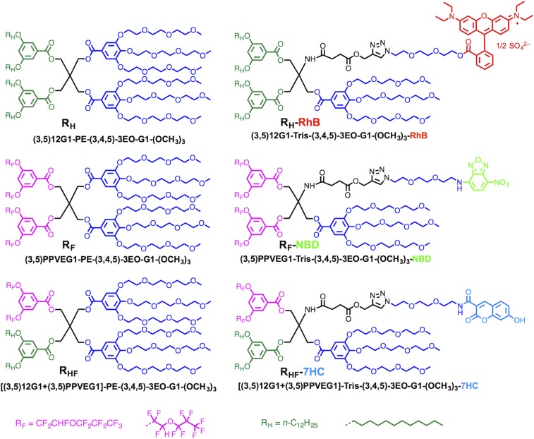
A library of six JDs was used for the coassembly of JDSs, including one with hydrogenated hydrophobic dendrons denoted RH, one with fluorinated hydrophobic perfluoropropyl vinyl ether (PPVE)-based dendrons (24) denoted RF, and one with hybrid hydrogenated–fluorinated hydrophobic dendrons denoted RHF, and their dye-tagged analogs. These molecules are illustrated with their long and short names in Fig. 1.
Fig. 1.
The library containing JDs with RH, RF, and hybrid RHF chains, and red fluorescent probe (RhB) labeled JD with RH chains, green fluorescent probe (NBD) labeled JD with RF chains, and blue fluorescent probe (7HC) labeled JD with hybrid RHF chains.
The dye-tagged JDs were prepared to visualize the coassembly of the three-component RH, RF, and RHF mixtures. In particular, a JD with hydrogenated hydrophobic dendrons was tagged with the red fluorescent dye rhodamine B (RhB) and denoted RH-RhB, a JD with fluorinated hydrophobic dendrons was tagged with the green fluorescent dye 7-nitrobenzofurazan (NBD) and denoted RF-NBD, and a JD with hybrid hydrogenated–fluorinated hydrophobic dendrons was tagged with the blue fluorescent dye 7-hydroxycoumarin (7HC) and denoted RHF-7HC. This enabled the visualization of each component in the assemblies by fluorescence microscopy.
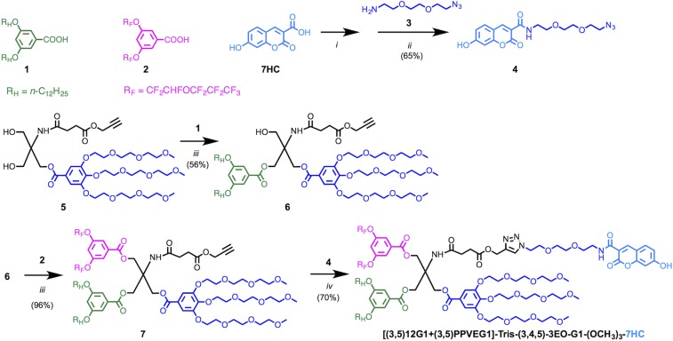
The syntheses of all of these molecules have been reported previously (23), with the exception of the synthesis of RHF-7HC, which is shown in Fig. 2. This compound was synthesized to visualize the role of RHF during the coassembly process. Therefore, compared with earlier studies (23) RHF provides a tool to investigate the coassembly process. The carboxyl group on the blue fluorescent dye 7HC underwent amidation with amine 3 to give 4, the azide-conjugated dye with oligo(ethylene oxide) spacer. The tris(hydroxymethyl)aminomethane (Tris)-based scaffolding 5 has been extensively used for the synthesis of JDs including the other dye-tagged JDs in Fig. 1, and its synthesis, which was originally developed for the preparation of Janus glycodendrimers (25), has been reported previously. A stepwise esterification was performed to couple the hydrogenated hydrophobic dendron 1 and the fluorinated hydrophobic PPVE dendron 2 to the hydroxyl groups on 5 in an analogous procedure to the one previously reported for the preparation of RHF. In the final step, the azide-functionalized dye 5 was coupled with the alkyne on JD scaffolding 7 via copper-catalyzed click chemistry to give the desired hybrid RHF-7HC.
Fig. 2.
Synthesis of blue fluorescent probe (7HC) labeled JD with hybrid RHF chains. Reagents and conditions: (i) HOSu, EDC, DMF, 0 °C for 1 h, then 23 °C for 12 h; (ii) N,N-diisopropylethylamine (DIPEA), DMF, 23 °C, 12 h; (iii) 4-(dimethylamino)pyridinium 4-toluenesulfonate, DCC, DCM, 23 °C for 12 h; and (iv) CuSO4·5H2O, sodium ascorbate, THF, water, 23 °C for 12 h.
Confocal Microscopy of the Coassembly of JDs with RF, RH, and Hybrid RHF Chains into JDSs.
Visualization by fluorescence microscopy required the preparation of giant assemblies with diameters greater than 1 μm by the thin film hydration method on a Teflon sheet. All experiments were conducted in PBS with a 1:1 ratio of RH to RF while the relative ratio of the third component RHF was altered. Hydration occurred at 60 °C for 12 h, after which the samples were vortexed and cooled to room temperature. Previous assemblies prepared with 50%, 40%, 34%, and 0% RHF by weight were reported, giving rise to various vesicular architectures with increasing separation of the hydrogenated and fluorinated components (23). Further tuning of RHF percentages between 34% and 0% is reported here and reveals the coassembly of a previously (23) unreported structure that, as will be discussed later, is frequently encountered in biological membranes.
In initial experiments, coassembly was conducted with 40% RH, 40% RF, and 20% RHF along with 1% of the red fluorescent hydrogenated analog RH-RhB and 1% of the green fluorescent fluorinated analog RF-NBD. Previously, it was demonstrated that RH and RF, due to the immiscibility of hydrogenated and fluorinated chains, preferentially coassemble with their respective dye-tagged analogs, enabling visualization of the fluorinated and hydrogenated components of their supramolecular assemblies (23). By viewing the same assemblies through different fluorescence channels, it is possible to visualize the various contributions of each molecule to the overall structure.
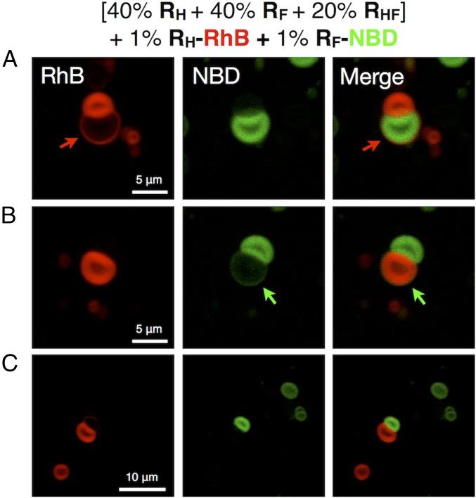
As shown in Fig. 3, at the prepared ratio of the three components, a unique structure denoted as a JDS was obtained, exhibiting two vesicles, one hydrogenated and the other fluorinated, locked together in a dumbbell shape. In Fig. 3A, a thin red hydrogenated ring extending from the red hydrogenated vesicle (marked by the red arrows) is visible surrounding the green fluorinated vesicle. The reverse construction, though less common, with a thin green fluorinated ring (marked by the green arrows) surrounding the red hydrogenated vesicle was also observed as shown in Fig. 3B. These structures coexisted with a large portion of completely self-sorted fluorinated and hydrogenated vesicles as evidenced by Fig. 3C.
Fig. 3.
Representative confocal fluorescent microscopy images (A–C) of assemblies from mixtures of RH, RF, and hybrid RHF JDs with proportions (in wt%) of RH = 40%, RF = 40%, and RHF = 20%. Mixtures contain an additional 1% (wt/wt) of RH-RhB and 1% (wt/wt) RF-NBD. Red and green fluorescent images were merged into one to demonstrate their self-sorting and coassembly.
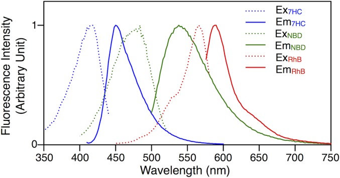
To better elucidate the role of the hybrid RHF JD in the formation of these dumbbell-shaped assemblies, a dye-tagged analog of RHF was synthesized as discussed above and denoted RHF-7HC. The blue fluorescent dye 7HC was chosen to ensure sufficient separation between the fluorescence wavelengths of each dye-tagged JD. Fig. S1 demonstrates the clear separation between the excitation and emission spectra of giant DSs prepared separately with RH, RF, and RHF and 1% of their respective dye-tagged analogs. By synthesizing a blue fluorescent JD with a distinct signal, interference between the blue and green dyes was avoided so that fluorescence microscopy could reliably be used to locate RHF in the assemblies.
Fig. S1.
Excitation (dash lines) and emission (solid lines) spectra of giant DSs prepared by [RH + 1% (wt/wt) RH-RhB] (RhB, red lines), [RF + 1% (wt/wt) RF-NBD] (NBD, green lines), and [RHF + 1% (wt/wt) RHF-7HC] (7HC, blue lines).
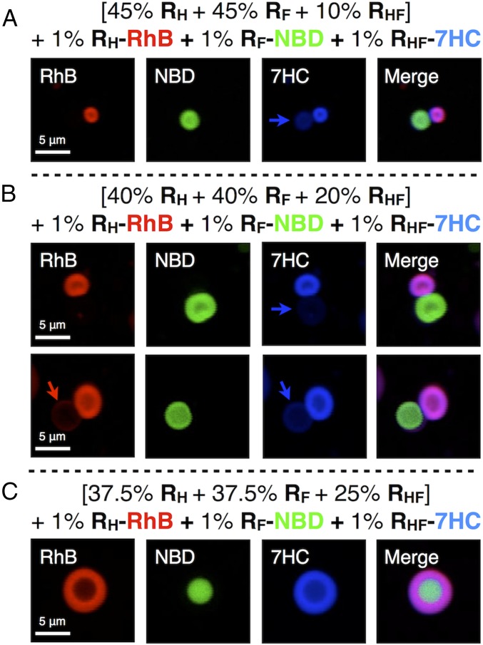
With the new dye-tagged hybrid JD in hand, coassembly was conducted with 40% RH, 40% RF, and 20% RHF along with 1% of the red fluorescent hydrogenated analog RH-RhB, 1% of the green fluorescent fluorinated analog RF-NBD, and 1% of the blue fluorescent hybrid hydrogenated–fluorinated analog RHF-7HC. As shown in Fig. 4B, the dumbbell-shaped assemblies were observed, and the blue fluorescence channel indicated the preferential segregation of the hybrid JD into the hydrogenated regions of the assembly. It should be noted that a minor fraction of the hybrid JD was observed in the fluorinated regions of the assembly as evidenced by faint blue fluorescence (marked by the blue arrows) corresponding to the location of the green fluorinated vesicles. When all fluorescence channels were merged, the red fluorescence and the blue fluorescence mixed to appear purple, while the green fluorescence remained about the same. This separation was indicative of the higher miscibility of the hybrid JD with the hydrogenated JD. Although no thin ring was observable surrounding either the fluorinated or hydrogenated vesicles in the top assembly in Fig. 4B, a thin red hydrogenated ring was visible surrounding the fluorinated vesicle in the bottom assembly as marked by the red arrow. Additionally, a brighter blue fluorescence was observed around the fluorinated region of the assembly (marked with the blue arrow) corresponding to the greater miscibility of the hybrid JD in the encompassing hydrogenated ring compared with the fluorinated vesicle. When the channels were merged, a thin purple ring consisting of the hybrid and hydrogenated JDs was partially visible surrounding the green fluorinated vesicle.
Fig. 4.
Representative confocal fluorescent microscopy images (A–C) of assemblies from mixtures of RH, RF, and hybrid RHF JDs with proportions (in wt%) of (A) RH = 45%, RF = 45%, RHF = 10%; (B) RH = 40%, RF = 40%, RHF = 20%; (C) RH = 37.5%, RF = 37.5%, RHF = 25%. Mixtures contain an additional 1% (wt/wt) of RH-RhB, 1% (wt/wt) RF-NBD, and 1% (wt/wt) RHF-7HC. Red, green, and blue fluorescent images were merged into one to demonstrate their self-sorting and coassembly.
Additional ratios of the three major components were also tested to determine a threshold for the formation of the dumbbell-shaped assemblies. When the percentage of RHF was increased to 25% from 20% and the percentages of RH and RF were reduced from 40% to 37.5% each, the dumbbell-shaped assemblies were no longer observed. Instead, core-shell assemblies were present as previously reported for RHF at 34% (23). Fig. 4C shows an example of one of these assemblies, demonstrating the presence of a red hydrogenated shell surrounding a filled green fluorinated core. Again, the hybrid JD was observed to preferentially localize in the red hydrogenated region as indicated by the blue fluorescence channel and the merged image. It was thus apparent that even a slight increase in the percentage of the hybrid JD resulted in the formation of an alternative structure. On the other hand, when the percentage of RHF was reduced to 10% and the percentages of RH and RF were increased to 45% each, the dumbbell-shaped assemblies were still observed as shown in Fig. 4A. However, these structures were significantly smaller than those obtained at 20% RHF, indicating that the size of the assemblies could be tuned by the relative percentage of RHF, with size decreasing with decreasing percentage of RHF. This also serves to highlight the sensitive role of RHF in controlling the assembly and sorting behavior of RH and RF. It should be noted that JDSs were observed to remain stable up to physiological temperature. Further characterization of the temperature dependency of JDSs is currently underway.
Nanoscale Visualization with Cryo-TEM.
The low resolution of confocal fluorescence microscopy made a detailed view of the JDSs unachievable by this method. However, the relatively large thickness of the vesicle membranes compared with the thinner rings surrounding the fluorinated or hydrogenated vesicles suggested the structures were multilamellar. This hypothesis was also supported by cryogenic transmission electron microscopy (cryo-TEM) images of vesicles prepared separately from RF and RHF, as reported previously, which showed those vesicles were multilamellar. In fact, RHF formed particularly well-defined onion-like vesicles (23).
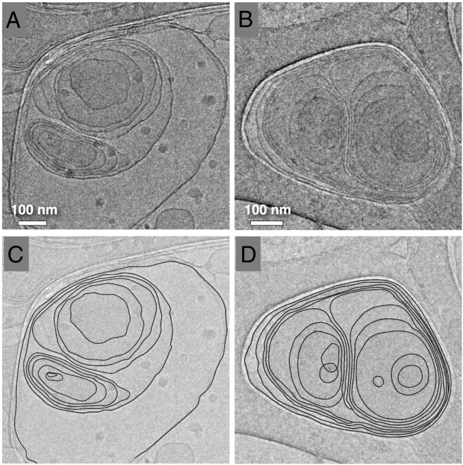
To better elucidate the structures of the JDSs, cryo-TEM was used to visualize the individual membranes that make up the assemblies. To do so, submicron analogs had to be assembled. This was achieved by preparing a THF solution containing 40% RH, 40% RF, and 20% RHF and rapidly injecting it into PBS at room temperature to give a final concentration of 0.5 mg/mL of JD in PBS. Fig. 5 shows selected images of the submicron dumbbell-shaped assemblies formed by this method along with traces of their bilayer contours. In both assemblies, multiple membranes encompass two onion-like vesicles. The left image clearly shows two separate onion-like vesicles forced together by the encompassing membrane. On the other hand, in the right image, in which the dumbbell assembly is squeezed within the lacey carbon architecture of the cryo-TEM grid, it is more difficult to clearly distinguish the membranes of each vesicle from each other. The outer membrane of the left vesicle even appears to cross over to the right vesicle in a manner suggestive of a disclination (26–28) in which a single membrane diverges into two (see bottom center of Fig. 5D). However, the low resolution of the cryo-TEM image prevents any definitive conclusions about the possible role of membrane defects in the formation of the JDSs. Additionally, since fluorinated and hydrogenated vesicles cannot be discriminated (distinguished) in cryo-TEM, it cannot be definitively proven that the dumbbell-shaped assemblies observed consist of self-sorted fluorinated and hydrogenated vesicles tethered together by an encompassing membrane as observed by fluorescence microscopy. Still, the cryo-TEM images provide valuable insight into the not yet fully elucidated JDS structure, including clear evidence of a multilamellar design. Additionally, cryo-TEM images of submicron analogs of the core-shell structures reported for 37.5% RH, 37.5% RF, and 25% RHF indicate that they consist of onion-like vesicles (Fig. S2).
Fig. 5.
Representative cryo-TEM images (A and B) of submicron assemblies from mixtures of RH, RF, and hybrid RHF JDs with proportions (in wt%) of RH = 40%, RF = 40%, and RHF = 20% prepared by injection of their THF solution into PBS to give a final concentration 0.5 mg/mL. Black lines were added to the images (C and D) to demarcate the contours of the bilayers.
Fig. S2.
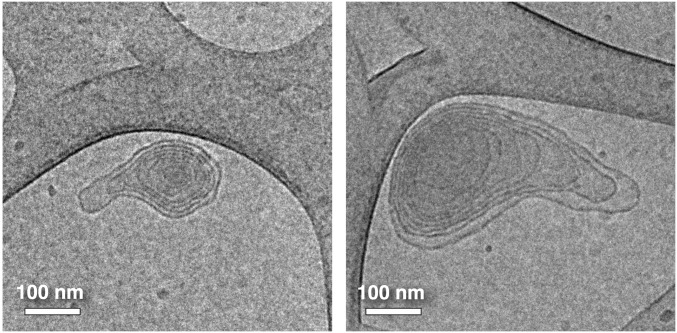
Representative cryo-TEM images of submicron assemblies from mixtures of RH, RF, and hybrid RHF JDs with proportions (in wt%) of RH = 37.5%, RF = 37.5%, and RHF = 25% prepared by injection of their THF solution into PBS to give a final concentration 0.5 mg/mL.
It should be noted that structures similar to JDSs have been observed by TEM and cryo-TEM to occur statistically in both synthetic and biological systems, albeit without the unique presentation of two vesicles with different physical properties. For instance, the self-assembly of phosphatidylcholine (PC), cholesterol, and various cosurfactants resulted in an almost identical structure to those in the cryo-TEM images reported herein but coexisting with mainly individual multilamellar vesicles (28). Multilamellar bodies in biological systems have also exhibited structures almost identical to those reported herein, suggesting the possible utility of JDSs as models (29, 30).
Proposed Model for Coassembly and Self-Sorting of JDs with RF, RH, and Hybrid RHF Chains.
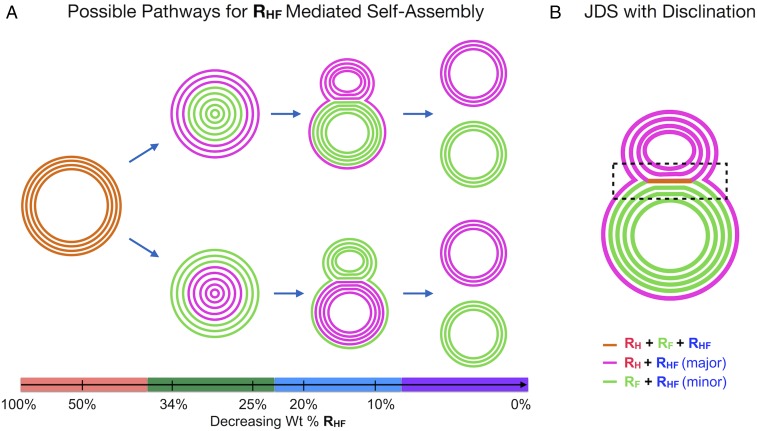
With the available information, a pathway for the coassembly and self-sorting of RF, RH, and RHF can be proposed as a function of the weight percentage of RHF as illustrated in Fig. 6A. The colored lines in the diagram represent bilayers of different compositions, as indicated in the legend. At 50% RHF, onion-like vesicles form that are homogenously composed of all three JD components (orange lines). As RHF is reduced to 34%, the homogenous vesicles separate into a core-shell structure with the core composed of either the fluorinated JDs (green lines) or the hydrogenated and hybrid JDs (purple lines) as a tightly formed onion-like vesicle and the shell consisting of the opposite component also exhibiting a multilamellar structure. In the diagram, a major fraction of RHF is illustrated to localize in the RH bilayers as was experimentally observed. When RHF is further reduced to 20%, additional separation of the fluorinated and hydrogenated components is observed, resulting in the partial fission of the assembly into JDSs that exhibit two vesicles connected in a dumbbell-like shape due to an encompassing outer membrane and possible disclinations. Finally, when the percentage of RHF is reduced toward 0%, complete separation of the fluorinated and hydrogenated components into isolated multilamellar vesicles is observed. It should be noted that two parallel pathways are described, with one showing the hydrogenated JDs localizing on the outside of the assemblies and the other showing the fluorinated JDs localizing on the outside of the assemblies. Structures corresponding to both of these pathways were experimentally observed, but structures from the top pathway were more common for reasons not yet understood.
Fig. 6.
Cartoon (A) illustrating the proposed coassembly and self-sorting pathways of mixtures of RH, RF, and hybrid RHF JDs in aqueous solution as a function of the concentration of RHF. Each structure shown is stable at room temperature in the given concentration range of RHF. Highlighting on the x axis below each structure spans the probable ranges of RHF percentages for which those structures exist. Cartoon B illustrates an alternative structure of JDSs, in which disclinations at the meeting of the hydrogenated and fluorinated vesicles, as well as an encompassing bilayer surrounding both vesicles, hold the two together as highlighted by the dashed box. The colored lines in both cartoons represent bilayers composed of RF, RH, and RHF as indicated in the legend.
The schematic structures proposed in Fig. 6A for the JDSs are most consistent with the cryo-TEM image in Fig. 4A, in which two distinct onion-like vesicles are held together by an encompassing outer bilayer. An alternative structure incorporating disclinations between the hydrogenated and fluorinated vesicles is shown in Fig. 6B and was inspired by the cryo-TEM image in Fig. 5B. In this proposed structure, a bilayer (orange line) at the meeting of the fluorinated and hydrogenated vesicles contains all three JDs and serves to lock the structure together along with an encompassing bilayer surrounding both vesicles. Disclinations at each end of this three-component bilayer result in its division into separate hydrogenated and fluorinated bilayers, which in turn form the basis of the separate hydrogenated and fluorinated vesicles.
It should be noted that more than 10 experiments were performed within the range of compositions that JDSs have been observed to exist, and in every case, JDSs were consistently observed as shown in the representative confocal fluorescence microscopy images from Figs. 3 and 4. This highlights their very high level of reproducibility. Additionally, JDSs were repeatedly observed in the same samples more than 6 wk after the initial preparation, indicating the persistence of these structures in time. The models presented in Fig. 6 were developed after reviewing all available fluorescence microscopy images from multiple different preparations in conjunction with cryo-TEM images to provide the most probable architectures of JDSs and the other structures shown in the pathway.
Three-Component JD System as Model of Biological Fusion and Fission.
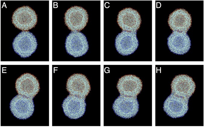
Fusion is the process by which two vesicles merge to become a single vesicle, whereas fission is the process by which a single vesicle splits into two separate ones. Both processes, which are involved in cell uptake, secretion, communication, and division for instance, are vital for the survival and proliferation of cells and are driven by various proteins (31–33). Synthetic models of vesicle fusion have been reported previously in giant liposome and polymeric vesicle systems, often with the aid of various ligands and ions replicating the roles of proteins in biological systems (34–39). Additionally, vesicle fusion has been modeled with computer simulations for both unilamellar and multilamellar vesicles (40–44). Previously reported coarse-grained (CG) molecular dynamics (MD) simulations of the interactions between two liposomes composed of dimyristoyl phosphatidylcholine (DMPC) exhibited no initiation of fusion even after applying a force (41). Movie S1 shows the two vesicles deform against one another when a force is applied and then move apart after the force is released. Thus, it is apparent that liposomes tend not to undergo fusion events without the assistance of complex machinery such as fusion proteins. CG-MD simulations of two liposomes composed of dioleoyl phosphatidylethanolamine (DOPE) with an initial stalk between them demonstrated the initiation of a fusion event with exchange of phospholipids between vesicles (Fig. S3 and Movie S2). The formation of disclinations at the meeting of the two vesicles resulted in a dumbbell-like structure. The simulation thus provides evidence of the role of disclinations in the formation of architectures similar to JDSs. However, the formation of the dumbbell-like structure was only possible when the initial condition of the simulation included a stalk between the two vesicles. Furthermore, the formation of the dumbbell-like structure was observed specifically for liposomes assembled from DOPE. An analogous simulation with liposomes assembled from DMPC exhibited repulsive behavior, eliminating the initial stalk to form two separate vesicles. It is apparent that the composition of liposomes impacts the ease with which they undergo fusion.
Fig. S3.
CG-MD simulation of the interaction between two liposomes composed of DOPE (each containing 1,512 molecules) at (A) 0 ns, (B) 7 ns, (C) 21 ns, (D) 36 ns, (E) 50 ns, (F) 64 ns, (G) 79 ns, and (H) 100 ns. Outer leaflets of two liposomes were initially connected through a channel with a diameter of bilayer thickness to mimic an ordinary stalk structure (40).
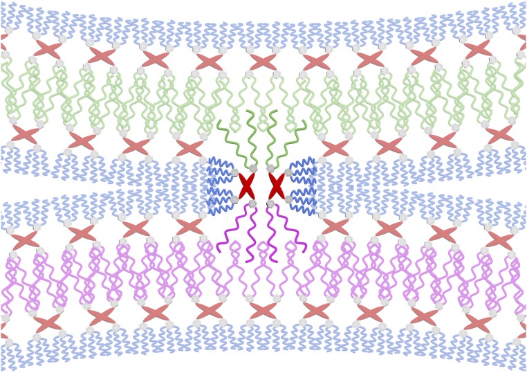
The diagram in Fig. 6A, regardless of the specific structures of the JDSs, takes the form of a fission pathway, in which a homogenous vesicle splits into separate vesicles based on the immiscibility of its components, and the reverse pathway depicts fusion. Furthermore, the addition of ligands, ions, and proteins was not required to observe structures indicative of fusion and fission processes. Self-sorting of the fluorinated and hydrogenated JD components may occur laterally within a bilayer to give a fluorinated and a hydrogenated domain, which then undergo fission to afford two separate vesicles. Sorting may also occur between the two monolayers of a single bilayer by the flip-flopping of JDs from one monolayer to the other, and sorting may occur between two bilayers by migration of JDs from one bilayer to another. It is possible that the barriers for the flip-flopping of JDs and their detachment from a bilayer are significantly lower than the same processes for phospholipids due to less dense packing of hydrophobic chains, promoting repartitioning of the JD system. Thus, fusion and fission may be achieved with specific mixtures of membrane building blocks rather than with complex systems of ligands, ions, and proteins. The hybrid JD RHF may serve to stabilize intermediates in this process such as JDSs. It is possible that the formation of stable JDSs results from the trapping of a fission or fusion process at a hemifusion-like intermediate due to the immiscibility of RH and RF. The hybrid JD RHF may stabilize the interface between the fluorinated and hydrogenated vesicles by inserting a fluorinated dendron into a fluorinated bilayer and a hydrogenated dendron into a hydrogenated bilayer as depicted in Fig. 7. The spanning of bilayers by RHF may also be responsible for the formation of membrane defects such as disclinations, as schematized in Fig. 6B. An analogous bridging between bilayers has been simulated with phospholipids in liposomes and is thought to be an important intermediate in fusion (45). Simulations and experiments designed to test these hypotheses are currently underway and will be reported in the future.
Fig. 7.
Cartoon illustrating two RHF molecules bridging a hydrogenated bilayer and a fluorinated bilayer by inserting their hydrogenated dendrons into the hydrogenated bilayer and their fluorinated dendrons into the fluorinated bilayer. Color code: blue, hydrophilic tri(ethylene oxide) chains; gray, aromatic rings; red, pentaerythritol core; pink, hydrophobic fluorinated chains; green, hydrophobic hydrogenated chains.
At the limit for which the concentration of RHF is zero, it is even possible that an analogous pathway to that shown in Fig. 6A is followed for the self-sorting of RH with RF alone. By adding increasing amounts of RHF to the system, this pathway can be trapped at a specific point depending on the concentration of RHF, which modulates the miscibility of RH with RF, essentially stabilizing structures that would be unstable otherwise. At high concentrations of RHF, miscibility of all three components is great enough to render homogenous vesicles stable. However, when the concentration of RHF is reduced, the miscibility of RH with RF gradually decreases such that each component along the fission pathway in Fig. 6 becomes stable within a narrow percentage range of RHF at room temperature. In effect, RHF pauses the self-sorting pathway at a specific moment as a function of its concentration, enabling the whole process to be visualized. Definitive proof of this concept has yet to be realized, but it is a logical possibility for explaining the unique coassembly and self-sorting behavior observed in this three-component JD system.
Conclusion
The coassembly of hydrogenated, fluorinated, and hybrid hydrogenated–fluorinated JDs at specific ratios into JDSs represents the discovery of a unique class of supramolecular JPs with dumbbell-shaped vesicular architectures. One side of the dumbbell consists of a fluorinated onion-like vesicle, and the other side consists of a hydrogenated onion-like vesicle. In most cases, the fluorinated onion-like vesicles appear to be encapsulated within hydrogenated membranes extending from the hydrogenated onion-like vesicles, although the reverse architecture has also been more rarely observed. The exact nature of the structure at the meeting of the two vesicles remains incompletely resolved, but it is hypothesized that membrane defects such as disclinations may play a role. Additionally, it has been shown that the hybrid JDs preferentially sort into the hydrogenated bilayers with a smaller fraction present in the fluorinated bilayers. As the concentration of hybrid JD decreases relative to the concentrations of the hydrogenated and fluorinated JDs, progressively more separated structures were observed, with the highest relative concentrations of hybrid JD affording homogenous onion-like vesicles and the lowest relative concentrations of hybrid JD affording JDSs and ultimately completely self-sorted hydrogenated and fluorinated vesicles in the absence of any hybrid JD. Thus, the ability of the hybrid JD to increase the miscibility of the hydrogenated and fluorinated JDs with each other appears to be responsible for the formation of JDSs and other unusual architectures at narrow ranges of the ratios of each component. The hybrid JD may also serve to stabilize the interface between hydrogenated and fluorinated vesicles in JDSs by bridging between their bilayers. Fluorinated and hybrid hydrogenated–fluorinated JDs designed from additional fluorinated building blocks that stabilize (46–48) rather than destabilize (24) supramolecular assemblies will be reported soon.
These findings are significant as models for fusion and fission in biological systems. Apparently, nonstatistical processes of fusion and fission can be achieved in the absence of complex additives such as fusion proteins. It is expected that three-component systems of phospholipids, as opposed to JDs, also exhibit similar properties to those observed in this study, opening up the possibility of non–protein-mediated fusion and fission in living cells. In fact, structures similar to JDSs have been observed in synthetic liposomes and in multilamellar bodies in biological systems, and JDSs may provide valuable insight into the mechanism by which these related structures form. Although little attention has been paid to the formation and presence of these dumbbell-like structures in biological systems, they may be indicative of non–protein-mediated fusion and fission of cells—a fundamental process that has been largely ignored but that may have major implications in biology and in medicine.
Methods
Preparation of DS by Injection.
A mixed stock solution was prepared by dissolving the required amount of amphiphilic JDs in ethanol. DSs were then generated by injection of 50 μL of the stock solution into 1 mL PBS, followed by 5 s of vortexing.
Preparation of Giant DS by Film Hydration.
A mixed solution of JDs (10 mg⋅mL−1, 200 μL) in THF was deposited on the top surface of a roughened Teflon sheet (1 cm2), placed in a flat-bottom vial, and followed by evaporation of the solvent for 2 h. The Teflon sheet was dried in vacuo for an additional 12 h. PBS (2.0 mL) was added to submerge the dendrimer film on the Teflon sheet, and the vial was placed in a 60 °C oven for 12 h for hydration. The sample was then mixed using a vortex mixer for 30 s with a final concentration of 1 mg⋅mL−1.
Confocal Fluorescence Microscopy.
An imaging chamber (5–10 μL) containing DSs was formed between two coverslips (25 × 25 mm, Fisher Scientific) sealed with vacuum grease. DSs were imaged by confocal fluorescence microscopy (FluoView 300 scanning system configured on a IX81 inverted microscope platform) with a 60 × 1.1 N.A. water immersion lens (Olympus). DSs containing RH-RhB were excited at a wavelength of λ = 543 nm, those containing RF-NBD were excited at a wavelength of λ = 488 nm, and those containing RHF-7HC were excited at a wavelength of λ = 405 nm. Laser intensities were adjusted so that fluorescence signal was not oversaturated. Image processing and analysis were completed with ImageJ 1.50 software.
Materials
All reagents were obtained from commercial sources and used without purification unless otherwise stated. CH2Cl2 (DCM) was dried over CaH2 and freshly distilled before use. DMF was dried from CaH2 or ninhydrin, distilled, and kept over molecular sieves before use. THF was distilled over Na/benzophenone immediately before use. Solvents and reagents were deoxygenated when necessary by purging with nitrogen. Milli-Q water obtained by Milli-Q UV plus with the resistivity 18.2 MΩ·cm was used for the preparation of PBS. PBS (1×) was obtained by dissolving 8 g of NaCl, 0.2 g of KCl, 1.44 g of Na2HPO4, and 0.24 g of KH2PO4 in 800 mL of Milli-Q water, adjusted to pH 7.4 and diluted to 1,000 mL.
Techniques
1H, and 13C NMR spectra were recorded at 500 MHz and 126 MHz, respectively, on a Bruker DRX (500 MHz) NMR spectrometer by Topspin. All NMR spectra were measured at 25 °C in CDCl3. Chemical shifts (δ) are reported in ppm, and coupling constants (J) are reported in Hertz (Hz). The resonance multiplicities in the 1H NMR spectra are described as “s” (singlet), “d” (doublet), “t” (triplet), “quint” (quintet), and “m” (multiplet), and broad resonances are indicated by “br.” Residual protic solvent of CDCl3 [1H, δ 7.26 ppm; 13C, δ 77.16 ppm (central resonance of the triplet)] and tetramethylsilane (TMS) were used as the internal reference in the 1H- and 13C-NMR spectra. The absorptions are given in wavenumbers (cm−1). Evolution of the reaction was monitored by TLC using silica gel 60 F254 precoated plates (E. Merck), and compounds were visualized by UV light with a wavelength of 254 or 356 nm. Purifications by flash column chromatography were performed using flash silica gel from Silicycle (60 Å, 40–63 μm) with the indicated eluent. The purity of the products was determined by a combination of TLC and high pressure liquid chromatography (HPLC) using Perkin-Elmer Series 10 high pressure liquid chromatograph equipped with an LC-100 column oven, Nelson Analytical 900 Series integrator data station, and two Perkin-Elmer PL gel columns of 5 × 10² and 1 × 10⁴ Å. THF was used as a solvent at the oven temperature of 40 °C. Detection was done by UV absorbance at 254 nm. MALDI-TOF mass spectrometry was performed on a PerSeptive Biosystem-Voyager-DE mass spectrometer equipped with nitrogen laser (337 nm) and operating in linear mode. Internal calibration was performed using Angiotensin II and Bombesin as standards. The analytical sample was obtained by mixing the THF solution of the sample (5–10 mg/mL) and THF solution of the matrix (2,5-dihydroxybenzoic acid, 10 mg/mL) in a 1/5 (vol/vol) ratio. The prepared solution of the sample and the matrix (0.5 μL) was loaded on the MALDI plate and allowed to dry at 23 °C before the plate was inserted into the vacuum chamber of the MALDI instrument. The laser steps and voltages applied were adjusted depending on both the molecular mass and the nature of each analyzed compound.
Synthesis
3,5-bis(dodecyloxy)benzoic acid (1) (11), 3,5-bis(1,1,2-trifluoro-2-(perfluoropropoxy)ethoxy)benzoic acid, (2) (23), 2-(2-(2-azidoethoxy)ethoxy)ethan-1-amine (3) (49), 7HC (50), 4-[[5-(hydroxylmethyl)-2,2-dimethyl-1,3-dioxan-5-yl]amino]-3-oxo-prop-2-yn-1-yl succinate (5) (25), and 4-(dimethylamino)pyridinium 4-toluenesulfonate (DPTS) (51) were prepared according to literature procedures.
Compound 4.
A DMF (4 mL) solution of 7HC (150 mg, 0.73 mmol) and N-hydroxysuccinimide (HOSu, 84 mg, 0.73 mmol) was cooled to 0 °C and 1-ethyl-3-(3-dimethylamino-propyl)carbodiimide (EDC) was added (168 mg, 0.88 mmol). The reaction mixture was allowed to stir at 0 °C for 1 h and at 23 °C for 12 h. The mixture was diluted with 200 mL of EtOAc and washed with 2 × 50 mL of water. The organic layer was dried over Na2SO4 and concentrated to dryness. The crude was used for the next step without further purification. The crude and 3 (127 mg, 0.73 mmol) was dissolved with 5 mL of DMF, and DIPEA (188 mg, 1.46 mmol) was added. The reaction mixture was allowed to stir at 23 °C for 12 h and concentrated to dryness. The crude product was further purified by column chromatography on silica gel with a mobile phase of EtOAc to yield compound 4 as a white solid (170 mg, 65%): 1H NMR (500 MHz, CDCl3) δ = 9.63 (br, 1H, OH), 9.18–9.20 (t, 1H, CONH, J = 5 Hz), 8.69 (s, 1H, CH = CCONH-), 7.48–7.50 (d, 1H, PhH, J1 = 8.5 Hz), 6.91–6.93 (dd, 1H, PhH, J1 = 8.5 Hz, J2 = 2.5 Hz), 6.88 (d, 1H, PhH, J2 = 2.5 Hz), 3.65–3.72 (m, 10H, 5×CH2), 3.37–3.39 (t, 2H, CH = CCOONHCH2CH2O-, J = 5 Hz); 13C NMR (500 MHz, CDCl3) δ = 163.8, 163.2, 161.9, 156.8, 148.7, 131.6, 115.1, 113.3, 111.7, 103.0, 70.7, 70.2, 69.6, 50.8, 40.0.
Compound 6.
To a DCM (10 mL) solution of compound 1 (0.69 g, 1.4 mmol), compound 5 (1.20 g, 1.4 mmol), and DPTS (0.42 g, 1.4 mmol), we added dicyclohexylcarbodiimide (DCC, 0.44 g, 2.1 mmol). The mixture was allowed to stir at 23 °C for 12 h. The precipitate was then filtered, and the filtrate was concentrated to dryness. The crude product was further purified by column chromatography on silica gel with a mobile phase of DCM/methanol = 20/1 (vol/vol) to yield compound 6 as a colorless oily liquid (1.05 g, 56%): 1H NMR (500 MHz, CDCl3) δ = 7.29 (s, 2H, 2×PhH), 7.11 (d, 2H, 2×PhH, J = 2 Hz), 6.63–6.64 (t, 1H, PhH, J = 2 Hz), 6.50 (br, 1H, CONH), 4.68–4.70 (m, 2H, 2×PhCOOCHHO), 4.59–4.62 (m, 4H, 2×PhCOOCHHO and COOCH2CCH), 4.22–4.24 (t, 2H, PhOCH2CH2O-, J = 5 Hz), 4.18–4.20 (t, 4H, 2×PhOCH2CH2O-, J = 5 Hz), 3.94–3.96 (m, 6H, 2×PhOCH2CH2CH2(CH2)8CH3 and CH2OH), 3.84–3.86 (t, 4H, 2×PhOCH2CH2O-, J = 5 Hz), 3.78–3.80 (t, 2H, PhOCH2CH2O-, J = 5 Hz), 3.70–3.73 (m, 6H, 3×PhOCH2CH2OCH2CH2O-), 3.62–3.66 (m, 12H, 3×PhOCH2CH2OCH2CH2OCH2CH2OCH3), 3.52–3.54 (m, 6H, 3×PhOCH2CH2OCH2CH2OCH2CH2OCH3), 3.36–3.37 (m, 3×PhOCH2CH2OCH2CH2OCH2CH2OCH3), 2.69–2.72 (t, 2H, NHCO-CH2CH2-COO, J = 6.5 Hz), 2.52–2.54 (t, 2H, NHCO-CH2CH2-COO, J = 6.5 Hz), 2.47–2.48 (t, 1H, COOCH2CCH, J = 2.5 Hz), 1.74–1.80 (m, 4H, 2×PhOCH2CH2CH2(CH2)8CH3), 1.41–1.47 (m, 4H, 2×PhOCH2CH2CH2(CH2)8CH3), 1.26–1.34 (m, 32H, 2×PhOCH2CH2CH2(CH2)8CH3), 0.86–0.89 (m, 6H, 2×PhOCH2CH2CH2(CH2)8CH3); 13C NMR (500 MHz, CDCl3) δ = 172.6, 172.1, 166.3, 166.0, 160.3, 152.4, 143.2, 131.0, 124.2, 109.4, 107.9, 106.6, 77.5, 75.2, 72.5, 71.9, 70.8, 70.7, 70.6, 70.5, 69.7, 69.0, 68.4, 63.8, 63.6, 63.3, 60.8, 59.0, 52.3, 31.9, 31.4, 29.7, 29.6, 29.6, 29.6, 29.4, 29.4, 29.3, 29.2, 26.1, 22.7, 14.1.
Compound 7.
To a DCM (10 mL) solution of compound 2 (0.20 g, 0.29 mmol), compound 6 (0.35 g, 0.265 mmol), and DPTS (86 mg, 0.29 mmol), we added DCC (137 mg, 0.66 mmol). The mixture was allowed to stir at 23 °C for 12 h. The precipitate was then filtered, and the filtrate was concentrated to dryness. The crude product was further purified by column chromatography on silica gel with a mobile phase of DCM/methanol = 10/1 (vol/vol) to yield compound 7 as a colorless oily liquid (504 g, 96%): 1H NMR (500 MHz, CDCl3) δ = 7.77–7.78 (d, 2H, 2×PhH, J = 2 Hz), 7.29 (s, 2H, 2×PhH), 7.23 (t, 1H, PhH, J = 2 Hz), 7.10–7.11 (d, 2H, 2×PhH, J = 2 Hz), 6.63 (t, 1H, PhH, J = 2 Hz), 6.58 (br, 1H, CONH), 6.08–6.19 (d, 2H, 2×CHF, J(HF) = 53 Hz), 4.78–4.91 (m, 6H, 6×PhCOOCHHO), 4.57 (d, 2H, COOCH2CCH, J = 2.5 Hz), 4.22–4.23 (t, 2H, PhOCH2CH2O-, J = 5 Hz), 4.17–4.19 (t, 4H, 2×PhOCH2CH2O-, J = 5 Hz), 3.93–3.95 (t, 4H, 2×PhOCH2CH2CH2(CH2)8CH3, J = 6.5 Hz), 3.84–3.86 (t, 4H, 2×PhOCH2CH2O-, J = 5 Hz), 3.78–3.80 (t, 2H, PhOCH2CH2O-, J = 5 Hz), 3.70–3.73 (m, 6H, 3×PhOCH2CH2OCH2CH2O-), 3.61–3.66 (m, 12H, 3×PhOCH2CH2OCH2CH2OCH2CH2OCH3), 3.51–3.54 (m, 6H, 3×PhOCH2CH2OCH2CH2OCH2CH2OCH3), 3.35–3.36 (m, 3×PhOCH2CH2OCH2CH2OCH2CH2OCH3), 2.67–2.69 (t, 2H, NHCO-CH2CH2-COO, J = 6.8 Hz), 2.50–2.53 (t, 2H, NHCO-CH2CH2-COO, J = 6.8 Hz), 2.44–2.45 (t, 1H, COOCH2CCH, J = 2.5 Hz), 1.74–1.79 (m, 4H, 2×PhOCH2CH2CH2(CH2)8CH3), 1.41–1.47 (m, 4H, 2×PhOCH2CH2CH2(CH2)8CH3), 1.26–1.34 (m, 32H, 2×PhOCH2CH2CH2(CH2)8CH3), 0.86–0.89 (m, 6H, 2×PhOCH2CH2CH2(CH2)8CH3); 13C NMR (500 MHz, CDCl3) δ = 172.0, 171.9, 166.1, 165.9, 163.7, 160.4, 152.5, 149.4, 143.3, 132.7, 130.9, 124.0, 120.9, 113.6–119.9 (CF), 109.4, 107.9, 106.7, 106.5–109.0 (CF), 96.5–99.0 (CF), 77.5, 75.1, 72.5, 72.0, 72.0, 70.9, 70.8, 70.7, 70.6, 70.6, 70.6, 69.7, 69.0, 68.4, 64.1, 63.5, 59.1, 59.0, 59.0, 52.2, 32.0, 31.4, 29.7, 29.7, 29.7, 29.6, 29.4, 29.4, 29.2, 29.2, 26.1, 22.7, 14.1.
[(3,5)12G1+ (3,5)PPVEG1]-Tris-(3,4,5)-3EO-G1-(OCH3)3-7HC.
To a mixed THF (10 mL) and water (1 mL) solution of compound 4 (19 mg, 0.05 mmol) and compound 7 (100 mg, 0.05 mmol), we added CuSO4·5H2O (13 mg, 0.05 mmol) in water (1 mL) and sodium ascorbate (20 mg, 0.1 mmol) in water (1 mL) successively under nitrogen atmosphere. The reaction mixture was allowed to stir at 23 °C for 24 h. The reaction mixture was concentrated to dryness. The crude product was further purified by column chromatography with a mobile phase of DCM/methanol = 20/1 (vol/vol) to yield compound [(3,5)12G1+ (3,5)PPVEG1]-Tris-(3,4,5)-3EO-G1-(OCH3)3-7HC as an colorless gel (82 mg, 70%). Purity (HPLC), 99%+: 1H NMR (500 MHz, CDCl3) δ = 9.02 (br, 1H, CONH), 8.62 (s, 1H, CH = CCONH-), 7.86 (s, 1H, triazole), 7.76 (d, 2H, 2×PhH, J = 2 Hz), 7.35–7.37 (d, 1H, PhH, J1 = 8.5 Hz), 7.27 (br, 1H, CONH), 7.20 (br, 1H, PhH), 7.08 (d, 2H, 2×PhH, J = 2 Hz), 6.84–6.86 (dd, 1H, PhH, J1 = 8.5 Hz, J2 = 2.5 Hz), 6.79 (d, 1H, PhH, J2 = 2.5 Hz), 6.63 (br, 1H, PhH), 6.09–6.20 (d, 2H, 2×CHF, J(HF) = 53 Hz), 5.15 (s, 2H, COOCH2-(C)triazole), 4.75–4.98 (m, 6H, 3×PhCOOCH2), 4.53–4.55 (t, 2H, triazole(N)-CH2CH2O, J = 5 Hz), 4.16–4.18 (t, 2H, PhOCH2CH2O, J = 5 Hz), 4.08–4.10 (t, 4H, 2×PhOCH2CH2O, J = 5 Hz), 3.90–3.92 (t, 4H, 2×PhOCH2CH2CH2(CH2)8CH3, J = 6.5 Hz), 3.85–3.87 (t, 2H, triazole(N)-CH2CH2O, J = 5 Hz), 3.80–3.84 (m, 4H, 2×CH2,), 3.75–3.77 (m, 1H, CH2), 3.69–3.71 (m, 6H, 3×CH2), 3.58–3.65 (m, 20H, 10×CH2), 3.51–3.54 (m, 6H, 3×CH2), 3.32–3.35 (m, 9H, 3×CH2), 2.64–2.67 (t, 2H, CH2, J = 6 Hz), 2.53–2.56 (t, 2H, CH2, J = 6 Hz), 1.70–1.77 (m, 4H, 2×PhOCH2CH2CH2(CH2)8CH3), 1.38–1.42 (m, 4H, 2×PhOCH2CH2CH2(CH2)8CH3), 1.24–1.27 (m, 32H, 2×PhOCH2CH2CH2(CH2)8CH3), 0.85–0.87 (m, 6H, 2×PhOCH2CH2CH2(CH2)8CH3); 13C NMR (500 MHz, CDCl3) δ = 172.7, 172.5, 166.1, 165.7, 163.8, 163.7, 162.7, 162.1, 160.4, 156.7, 152.5, 152.3, 149.4, 148.6, 142.9, 142.6, 132.8, 131.4, 131.0, 125.2, 124.1, 120.9, 113.6–119.9 (CF), 115.1, 113.4, 111.6, 109.1, 106.5–109.0 (CF), 108.0, 106.7, 96.5–99.0 (CF), 102.8, 70.7, 70.6, 70.6, 70.4, 69.7, 69.6, 69.4, 69.0, 68.9, 68.5, 64.1, 63.6, 63.4, 59.1, 59.0, 58.0, 50.4, 39.7, 32.0, 31.5, 29.8, 29.8, 29.7, 29.7, 29.7, 29.5, 29.4, 29.3, 26.1, 22.8, 14.2. MALDI-TOF (m/z), [M+Na]+ calculated for C103H137F20N5NaO33, 2374.9; found, 2,374.3.
Fluorescence Spectra
Fluorescence spectra for each fluorescence-labeled dendrimer were collected using an Infinite M1000 Pro microplate reader (Tecan). Peak excitation (Ex) and emission (Em) wavelengths were determined to be 418 nm/450 nm Ex/Em for RHF-7HC, 484 nm/538 nm Ex/Em for RF-NBD, and 566 nm/590 nm Ex/Em for RH-RhB.
Cryo-TEM
Cryo-TEM was performed on a JEOL 2100 microscope at a voltage of 200 kV. Briefly, a droplet of 2.5 μL DS solution was pipetted onto a lacey carbon film coated on a copper TEM grid (300 mesh, from Electron Microscopy Services) loaded into a Gatan Cp3 cryoplunger (Gatan). The sample was blotted by hand and then quickly plunged into liquefied ethane (∼90 K) cooled by a reservoir of liquid nitrogen to ensure the vitrification of water. The vitrified samples were transferred to a Gatan CT3500TR single tilt cryo transfer holder in a cryo-transfer stage immersed in liquid nitrogen. During the imaging, the cryo-holder was kept below −170 °C to prevent sublimation of vitreous solvent. The digital images were recorded by Orius SC200 or low-dose SerialEM camera. Image processing and analysis were completed with ImageJ 1.50 software.
Supplementary Material
Acknowledgments
The authors thank Benjamin E. Partridge for the preparation of Fig. 7 and Professor Matthew C. Good (Perelman School of Medicine, University of Pennsylvania) for inspiring discussions. The authors gratefully acknowledge financial support from National Science Foundation (NSF) Grants DMR-1066116 and DMR-1120901, the P. Roy Vagelos Chair at the University of Pennsylvania, and the Humboldt Foundation (all to V.P.); NSF Grant DMR-1120901 (to D.A.H. and M.L.K.); NIH Grant R01 GM097552 (to T.B.); and University of Pennsylvania Postdoctoral Opportunities in Research and Teaching (PENN-PORT) fellowship funded by the National Institute of General Medical Sciences Institutional Research and Career Development Award (IRACDA) 5 K12 GM081259-09) (to S.E.W.).
Footnotes
Conflict of interest statement: D.A.T. has an adjunct appointment at the University of Pennsylvania. It is not his primary affiliation.
This article contains supporting information online at www.pnas.org/lookup/suppl/doi:10.1073/pnas.1708380114/-/DCSupplemental.
References
- 1.Walther A, Müller AHE. Janus particles: Synthesis, self-assembly, physical properties, and applications. Chem Rev. 2013;113:5194–5261. doi: 10.1021/cr300089t. [DOI] [PubMed] [Google Scholar]
- 2.Allen TM, Chonn A. Large unilamellar liposomes with low uptake into the reticuloendothelial system. FEBS Lett. 1987;223:42–46. doi: 10.1016/0014-5793(87)80506-9. [DOI] [PubMed] [Google Scholar]
- 3.Immordino ML, Dosio F, Cattel L. Stealth liposomes: Review of the basic science, rationale, and clinical applications, existing and potential. Int J Nanomedicine. 2006;1:297–315. [PMC free article] [PubMed] [Google Scholar]
- 4.Bridson RH, et al. The preparation of liposomes using compressed carbon dioxide: Strategies, important considerations and comparison with conventional techniques. J Pharm Pharmacol. 2006;58:775–785. doi: 10.1211/jpp.58.6.0008. [DOI] [PubMed] [Google Scholar]
- 5.Discher BM, et al. Polymersomes: Tough vesicles made from diblock copolymers. Science. 1999;284:1143–1146. doi: 10.1126/science.284.5417.1143. [DOI] [PubMed] [Google Scholar]
- 6.Lee JS, Feijen J. Polymersomes for drug delivery: Design, formation and characterization. J Control Release. 2012;161:473–483. doi: 10.1016/j.jconrel.2011.10.005. [DOI] [PubMed] [Google Scholar]
- 7.Thiele J, Steinhauser D, Pfohl T, Förster S. Preparation of monodisperse block copolymer vesicles via flow focusing in microfluidics. Langmuir. 2010;26:6860–6863. doi: 10.1021/la904163v. [DOI] [PubMed] [Google Scholar]
- 8.Anajafi T, Mallik S. Polymersome-based drug-delivery strategies for cancer therapeutics. Ther Deliv. 2015;6:521–534. doi: 10.4155/tde.14.125. [DOI] [PMC free article] [PubMed] [Google Scholar]
- 9.Schulz M, Binder WH. Mixed hybrid lipid/polymer vesicles as a novel membrane platform. Macromol Rapid Commun. 2015;36:2031–2041. doi: 10.1002/marc.201500344. [DOI] [PubMed] [Google Scholar]
- 10.Ruysschaert T, et al. Hybrid nanocapsules: Interactions of ABA block copolymers with liposomes. J Am Chem Soc. 2005;127:6242–6247. doi: 10.1021/ja043600x. [DOI] [PubMed] [Google Scholar]
- 11.Percec V, et al. Self-assembly of Janus dendrimers into uniform dendrimersomes and other complex architectures. Science. 2010;328:1009–1014. doi: 10.1126/science.1185547. [DOI] [PubMed] [Google Scholar]
- 12.Peterca M, Percec V, Leowanawat P, Bertin A. Predicting the size and properties of dendrimersomes from the lamellar structure of their amphiphilic Janus dendrimers. J Am Chem Soc. 2011;133:20507–20520. doi: 10.1021/ja208762u. [DOI] [PubMed] [Google Scholar]
- 13.Percec V, et al. Modular synthesis of amphiphilic Janus glycodendrimers and their self-assembly into glycodendrimersomes and other complex architectures with bioactivity to biomedically relevant lectins. J Am Chem Soc. 2013;135:9055–9077. doi: 10.1021/ja403323y. [DOI] [PubMed] [Google Scholar]
- 14.Xiao Q, et al. Bioactive cell-like hybrids coassembled from (glyco)dendrimersomes with bacterial membranes. Proc Natl Acad Sci USA. 2016;113:E1134–E1141. doi: 10.1073/pnas.1525589113. [DOI] [PMC free article] [PubMed] [Google Scholar]
- 15.Sherman SE, Xiao Q, Percec V. Mimicking complex biological membranes and their programmable glycan ligands with dendrimersomes and glycodendrimersomes. Chem Rev. 2017;117:6538–6631. doi: 10.1021/acs.chemrev.7b00097. [DOI] [PubMed] [Google Scholar]
- 16.Le Meins J-F, Schatz C, Lecommandoux S, Sandre O. Hybrid polymer/lipid vesicles: State of the art and future perspectives. Mater Today. 2013;16:397–402. [Google Scholar]
- 17.Dietrich C, et al. Lipid rafts reconstituted in model membranes. Biophys J. 2001;80:1417–1428. doi: 10.1016/S0006-3495(01)76114-0. [DOI] [PMC free article] [PubMed] [Google Scholar]
- 18.Semrau S, Idema T, Holtzer L, Schmidt T, Storm C. Accurate determination of elastic parameters for multicomponent membranes. Phys Rev Lett. 2008;100:088101. doi: 10.1103/PhysRevLett.100.088101. [DOI] [PubMed] [Google Scholar]
- 19.Bezlyepkina N, Gracià RS, Shchelokovskyy P, Lipowsky R, Dimova R. Phase diagram and tie-line determination for the ternary mixture DOPC/eSM/cholesterol. Biophys J. 2013;104:1456–1464. doi: 10.1016/j.bpj.2013.02.024. [DOI] [PMC free article] [PubMed] [Google Scholar]
- 20.Christian DA, et al. Spotted vesicles, striped micelles and Janus assemblies induced by ligand binding. Nat Mater. 2009;8:843–849. doi: 10.1038/nmat2512. [DOI] [PMC free article] [PubMed] [Google Scholar]
- 21.Spinler K, et al. Dynamic domains in polymersomes: Mixtures of polyanionic and neutral diblocks respond more rapidly to changes in calcium than to pH. Langmuir. 2013;29:7499–7508. doi: 10.1021/la304602e. [DOI] [PMC free article] [PubMed] [Google Scholar]
- 22.Verberg R, Dale AT, Kumar P, Alexeev A, Balazs AC. Healing substrates with mobile, particle-filled microcapsules: Designing a ‘repair and go’ system. J R Soc Interface. 2007;4:349–557. doi: 10.1098/rsif.2006.0165. [DOI] [PMC free article] [PubMed] [Google Scholar]
- 23.Xiao Q, et al. Self-sorting and coassembly of fluorinated, hydrogenated, and hybrid Janus dendrimers into dendrimersomes. J Am Chem Soc. 2016;138:12655–12663. doi: 10.1021/jacs.6b08069. [DOI] [PMC free article] [PubMed] [Google Scholar]
- 24.Wilson CJ, Wilson DA, Feiring AE, Percec V. Disassembly via an environmentally friendly and efficient fluorous phase constructed with dendritic architectures. J Polym Sci A Polym Chem. 2010;48:2498–2508. [Google Scholar]
- 25.Zhang S, et al. Mimicking biological membranes with programmable glycan ligands self-assembled from amphiphilic Janus glycodendrimers. Angew Chem Int Ed Engl. 2014;53:10899–10903. doi: 10.1002/anie.201403186. [DOI] [PubMed] [Google Scholar]
- 26.Zasadzinski JA. Transmission electron microscopy observations of sonication-induced changes in liposome structure. Biophys J. 1986;49:1119–1130. doi: 10.1016/S0006-3495(86)83741-9. [DOI] [PMC free article] [PubMed] [Google Scholar]
- 27.Zasadzinski JAN, Kerins J, Davis HT, Scriven LE. Toward an understanding of liposome structure through the use of computer graphic image correlation. J Electron Microsc Tech. 1986;3:385–400. [Google Scholar]
- 28.Shiba H, Noguchi H, Gompper G. Structure formation of surfactant membranes under shear flow. J Chem Phys. 2013;139:014702. doi: 10.1063/1.4811239. [DOI] [PubMed] [Google Scholar]
- 29.Richard A, Delvaux J, Bourel-Bonnet L. Effects of sterilizing-grade filters on the physico-chemical properties of onion-like vesicles. Int J Pharm. 2006;312:144–150. doi: 10.1016/j.ijpharm.2006.01.007. [DOI] [PubMed] [Google Scholar]
- 30.Paquet VE, et al. Lipid composition of multilamellar bodies secreted by Dictyostelium discoideum reveals their amoebal origin. Eukaryot Cell. 2013;12:1326–1334. doi: 10.1128/EC.00107-13. [DOI] [PMC free article] [PubMed] [Google Scholar]
- 31.Südhof TC, Rothman JE. Membrane fusion: Grappling with SNARE and SM proteins. Science. 2009;323:474–477. doi: 10.1126/science.1161748. [DOI] [PMC free article] [PubMed] [Google Scholar]
- 32.Jahn R, Lang T, Südhof TC. Membrane fusion. Cell. 2003;112:519–533. doi: 10.1016/s0092-8674(03)00112-0. [DOI] [PubMed] [Google Scholar]
- 33.Kozlov MM, McMahon HT, Chernomordik LV. Protein-driven membrane stresses in fusion and fission. Trends Biochem Sci. 2010;35:699–706. doi: 10.1016/j.tibs.2010.06.003. [DOI] [PMC free article] [PubMed] [Google Scholar]
- 34.Haluska CK, et al. Time scales of membrane fusion revealed by direct imaging of vesicle fusion with high temporal resolution. Proc Natl Acad Sci USA. 2006;103:15841–15846. doi: 10.1073/pnas.0602766103. [DOI] [PMC free article] [PubMed] [Google Scholar]
- 35.Richard A, et al. Fusogenic supramolecular vesicle systems induced by metal ion binding to amphiphilic ligands. Proc Natl Acad Sci USA. 2004;101:15279–15284. doi: 10.1073/pnas.0406625101. [DOI] [PMC free article] [PubMed] [Google Scholar]
- 36.Marchi-Artzner V, Brienne M-J, Gulik-Krzywicki T, Dedieu J-C, Lehn J-M. Selective complexation and transport of europium ions at the interface of vesicles. Chemistry. 2004;10:2342–2350. doi: 10.1002/chem.200305423. [DOI] [PubMed] [Google Scholar]
- 37.Marchi-Artzner V, et al. Selective adhesion, lipid exchange and membrane-fusion processes between vesicles of various sizes bearing complementary molecular recognition groups. ChemPhysChem. 2001;2:367–376. doi: 10.1002/1439-7641(20010618)2:6<367::AID-CPHC367>3.0.CO;2-#. [DOI] [PubMed] [Google Scholar]
- 38.Voskuhl J, Ravoo BJ. Molecular recognition of bilayer vesicles. Chem Soc Rev. 2009;38:495–505. doi: 10.1039/b803782p. [DOI] [PubMed] [Google Scholar]
- 39.Yao W, Qian H, Zhang J, Wu W, Jiang X. Multifusion-induced wall-super-thick giant multilamellar vesicles. Chem Commun (Camb) 2012;48:7079–7081. doi: 10.1039/c2cc32387g. [DOI] [PubMed] [Google Scholar]
- 40.Shinoda W, Klein ML. Effective interaction between small unilamellar vesicles as probed by coarse-grained molecular dynamics simulations. Pure Appl Chem. 2014;86:215–222. [Google Scholar]
- 41.Shinoda W, DeVane R, Klein ML. Zwitterionic lipid assemblies: Molecular dynamics studies of monolayers, bilayers, and vesicles using a new coarse grain force field. J Phys Chem B. 2010;114:6836–6849. doi: 10.1021/jp9107206. [DOI] [PMC free article] [PubMed] [Google Scholar]
- 42.Lin C-M, Wu DT, Tsao H-K, Sheng Y-J. Membrane properties of swollen vesicles: Growth, rupture, and fusion. Soft Matter. 2012;8:6139–6150. [Google Scholar]
- 43.Lin Y-L, Chang H-Y, Sheng Y-J, Tsao H-K. The fusion mechanism of small polymersomes formed by rod-coil diblock copolymers. Soft Matter. 2014;10:1500–1511. doi: 10.1039/c3sm52387j. [DOI] [PubMed] [Google Scholar]
- 44.Chang H-Y, Lin Y-L, Sheng Y-J, Tsao H-K. Structural characteristics and fusion pathways of onion-like multilayered polymersome formed by amphiphilic comb-like graft copolymers. Macromolecules. 2013;46:5644–5656. [Google Scholar]
- 45.Markvoort AJ, Marrink SJ. Lipid acrobatics in the membrane fusion arena. Curr Top Membr. 2011;68:259–294. doi: 10.1016/B978-0-12-385891-7.00011-8. [DOI] [PubMed] [Google Scholar]
- 46.Johansson G, Percec V, Ungar G, Zhou JP. Fluorophobic effect in the self-assembly of polymers and model compounds containing tapered groups into supramolecular columns. Macromolecules. 1996;29:646–660. [Google Scholar]
- 47.Percec V, Johansson G, Ungar G, Zhou J. Fluorophobic effect induces the self-assembly of semifluorinated tapered monodendrons containing crown ethers into supramolecular columnar dendrimers which exhibit a homeotropic hexagonal columnar liquid crystalline phase. J Am Chem Soc. 1996;118:9855–9866. [Google Scholar]
- 48.Johansson G, Percec V, Ungar G, Smith K. Fluorophobic effect generates a systematic approach to the synthesis of the simplest class of rodlike liquid crystals containing a single benzene unit. Chem Mater. 1997;9:164–175. [Google Scholar]
- 49.Huang C-J, Hong C-W, Ko F-H, Chang F-C. Fabrication of vesicle-like dual-responsive click capsules by direct covalent layer-by-layer assembly. Soft Matter. 2011;7:10850–10855. [Google Scholar]
- 50.Mizukami S, Watanabe S, Hori Y, Kikuchi K. Covalent protein labeling based on noncatalytic β-lactamase and a designed FRET substrate. J Am Chem Soc. 2009;131:5016–5017. doi: 10.1021/ja8082285. [DOI] [PubMed] [Google Scholar]
- 51.Moore JS, Stupp SI. Room temperature polyesterification. Macromolecules. 1990;23:65–70. [Google Scholar]
Associated Data
This section collects any data citations, data availability statements, or supplementary materials included in this article.


