Abstract
Neurosurgeons currently base most of their treatment decisions for intracranial aneurysms (IAs) on morphological measurements made manually from 2D angiographic images. These measurements tend to be inaccurate because 2D measurements cannot capture the complex geometry of IAs and because manual measurements are variable depending on the clinician's experience and opinion. Incorrect morphological measurements may lead to inappropriate treatment strategies. In order to improve the accuracy and consistency of morphological analysis of IAs, we have developed an image-based computational tool, AView. In this study, we quantified the accuracy of computer-assisted adjuncts of AView for aneurysmal morphologic assessment by performing measurement on spheres of known size and anatomical IA models. AView has an average morphological error of 0.56% in size and 2.1% in volume measurement. We also investigate the clinical utility of this tool on a retrospective clinical dataset and compare size and neck diameter measurement between 2D manual and 3D computer-assisted measurement. The average error was 22% and 30% in the manual measurement of size and aneurysm neck diameter, respectively. Inaccuracies due to manual measurements could therefore lead to wrong treatment decisions in 44% and inappropriate treatment strategies in 33% of the IAs. Furthermore, computer-assisted analysis of IAs improves the consistency in measurement among clinicians by 62% in size and 82% in neck diameter measurement. We conclude that AView dramatically improves accuracy for morphological analysis. These results illustrate the necessity of a computer-assisted approach for the morphological analysis of IAs.
Keywords: Intracranial Aneurysm, Morphology, Computer-Assisted analysis
1. Introduction
Morphological parameters are important for intracranial aneurysm (IA) risk assessment and treatment guidelines. Aneurysm size is one of the primary parameters for treatment decisions, and neck diameter is measured to optimize IA treatments. Currently, clinicians measure these indices manually on 2D images (typically Digital Subtraction Angiography, DSA, Computed Tomography Angiography, CTA, or Magnetic Resonance Angiogram, MRA). In addition to size and neck diameter measurements, considering more complex 3D morphological factors, such as irregularity of aneurysm shape [1], or measurement of aneurysm volume [2], have been suggested for better management of IAs. However, 2D manual measurements of morphological parameters are subject to error and variability among clinicians. Therefore, there is a need for precise, accurate and user-friendly means for morphologic analysis of IAs.
We have developed AView as an image-based vascular analysis tool for rapid assessment of aneurysmal morphometrics and hemodynamics [3]. AView was a result of collaboration between biomedical engineers at University at Buffalo's Toshiba Stroke and Vascular Research Center, neurosurgeons at Gates Vascular Institute, and software developers at Orobix Srl (Bergamo, Italy).
AView segments 3D geometry of IAs based on algorithms in Vascular Modelling Toolkit, (VMTK, www.vmtk.org), and performs semi-automated computation of morphological indices. However, it is important to determine the accuracy of AView measurement and evaluate its clinical utility before its eventual clinical application. In this study, we introduce AView's morphological measurement tool and quantify its accuracy. We also retrospectively evaluate the clinical utility of AView's morphological tool by comparing 2D manual with 3D computer-assisted measurement of size and neck diameter of 10 IAs.
2. Methods
2.1 Morphology module
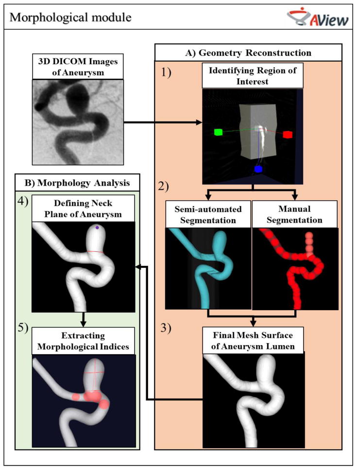
Figure 1 shows the workflow of AView morphological module.
Figure 1.

Morphological workflow of AView.
AView requires IA images in Digital Imaging and Communications in Medicine (DICOM) format. To access the AView morphological workflow, the user must navigate two sub-modules: A) Geometry Reconstruction, in which user segments and reconstructs the 3D geometry of the IA, and B) Morphology Analysis, to inspect the 3D geometry of the IA and extract the clinically relevant morphological parameters.
The reconstruction of IA geometries starts by defining the region of interest, or the region where the IA and parent arteries are visible (Figure 1-1). The user then initializes the aneurysm lumen surface and chooses between two approaches, semi-automated or manual segmentation (Figure 1-2). Semi-automated segmentation is a user-friendly approach that generates the initial surface when the user defines a threshold-based iso-surface. For aneurysms that have more complex anatomy, AView provides a manual approach in which user can define the aneurysms and parent arteries by manually placing a sequence of seed spheres on a maximum intensity projection (MIP) or on slices. Then, an initial surface is estimated by rendering an interpolating spline through the seeds. A detailed description of manual segmentation can be found in previous publications [3]. After generation of the initial surface, the final mesh surface will be extracted by evolving the initial surface towards the nearest maximum intensity gradient, which represents the lumen boundary (Figure 1-3).
After reconstruction of the IA geometry, the model can be trimmed and prepared for analysis. In the trimming module, the user can remove spurious features from the geometry, identify the inlet and outlet branches, and isolate the domain of interest from the rest of the vasculature network. Then, the user identifies the aneurysm neck plane (Figure 1-4) and AView automatically analyzes the IA sac. AView provides 17 morphological parameters which their clinical utilities have been shown before [4].
2.2 Validation of morphological workflow
The segmentation module uses 3D images to generate the 3D surface mesh of the IA lumen. However, it is important to quantify the accuracy of the generated geometry.
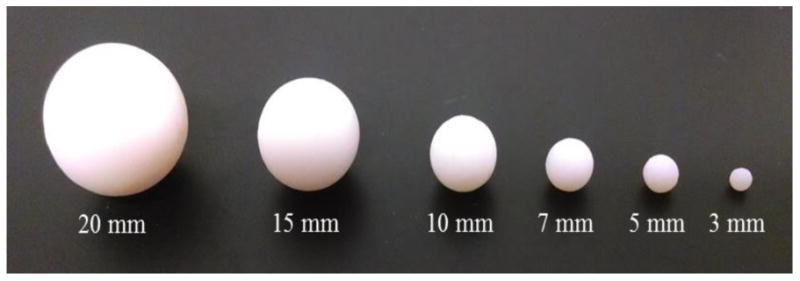
To validate the semi-automated segmentation module, we imaged spheres with known diameters and volumes (Figure 2) using 3D rotational X-Ray angiography cone beam CT (Toshiba Medical Systems Corp. Tustin, CA) at our research center. For imaging, we followed a similar protocol, voxel size = 0.223 × 0.223 × 0.223 mm3, to the one used at our clinical imaging site, Gates Vascular Institute (Buffalo, NY). After imaging, we performed segmentation and morphometric analysis (maximum size, volume) using AView and compared the results with the true size of the objects.
Figure 2.

3D spheres objects with known sizes.
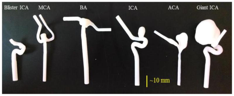
Next, we acquired and segmented six patient-specific IA geometries with sizes between 1.6 and 21.3 mm, as shown in Figure 2. The morphology of each IA was analyzed using an in-house MATLAB code (The MathWorks Inc., Natick, MA) [4]. We calculated the size and volume of each IA and considered them as true measurements. Then, the geometries were 3D printed using an Objet PolyJet 3D printer, Model260 V (Object-Stratasys, Inc. Eden Prairie, MN). The printer layer thickness of the 3D printer is 14 μm [5]. Therefore, we assumed that the 3D printer does not significantly change the IA geometry. Then, we imaged the 3D printed IA models using the approach previously explained, and analyzed the IAs morphology using AView. We compared the true size and volume of IAs with the results measured in AView.
2.3 2D manual versus 3D computer-assisted morphological analysis of IAs
After validation of the AView morphological measurement tool, we evaluated the clinical usefulness of the tool by comparing the 2D manual measurements with 3D computer-assisted measurements. We obtained Institutional Review Board approval (University at Buffalo), and randomly selected 10 patients with 2D and 3D DSA images that were diagnosed with IAs between 2012 and 2013. Three neuroendovascular fellows at Gates Vascular Institute (Buffalo, NY) measured morphological parameters that are routinely used in clinical practice.
First, clinicians were asked to perform the morphological analysis of IAs using their routine clinical approach. To this purpose, we provided them with the 2D DSA images of the aneurysms in anterior-posterior and lateral views. Clinicians used those images to find the best cross-sectional view of the aneurysm geometries and measured the size and neck diameter of IAs.
Next, clinicians performed the morphological analysis on same IAs using AView. To this purpose, clinicians were provided with the 3D geometry files of the IAs in StereoLithography (STL) format that were previously reconstructed. To analyze the morphology of each aneurysm, clinicians inspected the aneurysm's 3D geometry by rotating the STL model. Then, they defined the neck plain of each IA by drawing a line on the projection images of aneurysm (Figures 1 through 4). AView automatically analyzed the 3D geometry of aneurysm sac and provided 17 morphological parameters, including size and neck diameter of the IA. We compared the 2D manual and 3D computer-assisted measurements.
3. Results
3.1 Validation of morphological workflow
Table 1 shows the comparison of AView measurements with the known sizes of spherical objects. Results show an average of -0.89% difference in diameter and -3.21% difference in volume between AView calculations and the true sizes of the objects. Results also show that the difference increases for smaller objects; however, the maximum difference in size for the sphere with 3 mm diameter is only -2.00%. Table 2 shows the comparison of AView measurements with the true size of IA models. The results show an average difference of -0.23% for aneurysm size and 1.0% for aneurysm volume.
Table 1. Error quantification of AView measurement using sphere objects with known sizes.
| Sphere | Size (mm) | Volume (mm3) | ||||
|---|---|---|---|---|---|---|
| AView | True Value | Error | AView | True Value | Error | |
| 1 | 20.02 | 20.00 | 0.10 % | 4210.51 | 4188.79 | 0.52 % |
| 2 | 14.96 | 15.00 | -0.27 % | 1767.94 | 1765.15 | 0.16 % |
| 3 | 9.98 | 10.00 | -0.20 % | 522.81 | 523.60 | -0.15 % |
| 4 | 6.93 | 7.00 | -1.00 % | 176.66 | 179.59 | -1.63 % |
| 5 | 4.90 | 5.00 | -2.00 % | 62.56 | 65.45 | -4.42 % |
| 6 | 2.94 | 3.00 | -2.00 % | 12.20 | 14.14 | -13.72 % |
Table 2. Error quantification of AView measurement using anatomical models of IAs with known sizes.
| IA Models | Size (mm) | Volume (mm3) | ||||
|---|---|---|---|---|---|---|
| AView | True Value | Error | AView | True Value | Error | |
| Giant ICA | 20.77 | 21.27 | -2.35 % | 4291.99 | 4304.38 | -0.29 % |
| ACA | 14.3 | 14.42 | -0.83 % | 706.76 | 700.81 | 0.85 % |
| ICA | 9.07 | 8.99 | 0.89 % | 226.35 | 227.41 | -0.47 % |
| BA | 5.04 | 4.84 | 4.13 % | 100.17 | 95.07 | 5.36 % |
| MCA | 4.91 | 4.91 | 0.00 % | 87.49 | 89.37 | -2.10 % |
| Blister ICA | 1.51 | 1.56 | -3.21 % | 3.92 | 3.82 | 2.62 % |
3.2 2D manual versus 3D computer-assisted morphological analysis of IAs
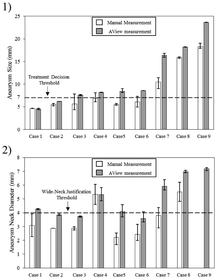
The clinicians who participated in this study measured the maximum diameter and maximum neck diameter of each IA. Figure 4-1 shows the comparison of 2D manual and 3D computer-assisted, AView, size measurements of all IAs. One aneurysm was recognized as fusiform IA and was excluded from our study. The results are organized based on the aneurysm size that was measured by AView. The results show that almost all the aneurysm sizes were underestimated, by an average of 22%, when clinicians used 2D manual approach. Bars in the figure represent the inter-user variability of the measurements by three clinicians. These results show a considerable range in 2D manual size measurement, with the average range of 1.4 mm. The average range of size measurement was reduced to 0.25 mm when they used 3D computer-assisted approach. A dashed line was also plotted to compare the aneurysm size measurements to the recommended size threshold for treatment, which implies aneurysms larger than 7 mm are justified for treatment [6]. For four IA cases, Cases 3-6, 2D manual approach underestimated aneurysm sizes less than the size threshold, however, 3D computer-assisted approach showed these aneurysms are larger than 7 mm.
Figure 4.

Comparison of 2D manual and 3D computer-assisted measurement of size and neck diameter of IAs. Bars present inter-user variablity in measurements.
Figure 4-2 shows the results of neck diameter measurements using both 2D manual and 3D computer-assisted, AView, approaches. Only one clinician could determine the aneurysm neck in Case 2, and no clinician could determine the aneurysm neck in Case 9. Similar to IA size measurement, clinicians underestimated the neck diameter by an average of 30% when they used 2D manual approach. Inter-user variability in measurements was illustrated using bars in the figure. The average range of 2D manual measurement between clinicians was 1.17 mm, which reduced to 0.44 mm when AView was used. As in aneurysm size measurement, a dashed line is plotted to show the cutoff threshold for the wide-neck classification of IAs, which implies that aneurysms with neck diameter larger than 4 mm are considered as wide-neck IAs [7]. 2D Manual measurement of three IA cases, Case 1, Case5 and Case 7, showed that the aneurysm neck diameters are less than 4 mm, however, AView categorized them as wide-neck aneurysms.
4. Discussion
Recent studies suggest that morphological characteristics of IAs are important for IA management. It has been recommended by American Heart Association that: “In addition to the size and location of the aneurysm and the patient's age and health status, it might be reasonable to consider morphological and hemodynamic characteristics of the aneurysm when discussing the risk of aneurysm rupture” [8]. Providing accurate morphometric information requires extensive knowledge and computational skills. Therefore, a mean to easily and accurately calculate such information is necessary.
Several attempts have been made previously to bring IA modeling tools to the clinical setting [9, 10]; however, all of them were faced with obstacles, such as being complicated, not being integrated, or being dependent on other stand-alone software. Based on years of experience through collaboration of biomedical engineers from the University at Buffalo's Toshiba Stroke and Vascular Research Center, neurosurgeons at Gates Vascular Institute and software developers at Orobix Srl (Bergamo, Italy), we have developed an integrated tool, AView, to rapidly assess morphometrics and hemodynamics of IAs in the clinical setting [3]. In order to bring such computational tools to clinical settings, the accuracy of the tools should be validated and their clinical usefulness should be explored.
In this study, we aimed to confirm the accuracy of AView morphological module. AView embeds VMTK algorithm for segmentation, which has been validated using a known-size internal carotid artery phantom [11]. Moreover, VMTK geometrical quantification of the IA shape is also validated on simple idealize bifurcation and aneurysm sidewall models [12]. Our results showed an ignorable error in size and volume measurement of sphere objects and anatomical IA models. Our findings, along with the previous validation studies [11, 12], confirms the high accuracy of the morphological module of AView for segmentation and morphological analysis of IAs.
We also compared the IA size and neck diameter measurements using 2D manual approach with computer-assisted approach, AView, and investigated the clinical impact of computer-assisted measurement and its potential improvement in morphological analysis of IAs, in clinical practice. The results showed that, in general, clinicians underestimate the IA size and neck diameter when 2D manual measurements are used. This finding is in agreement with the study by Groth et al. [13], in which for the first time they compared 2D manual measurement to 3D computer-assisted measurement. However, their computer-assisted approach was limited to MRI images; while digital subtraction angiography is well known as the gold standard for detection and morphological analysis of IAs [8].
Underestimation of aneurysm size can misguide clinical decisions. For example, if an aneurysm is incorrectly determined to be under a specific size threshold (for instance, 7mm [6]), which recommends observation of IAs, it may incorrectly misguide clinicians to assume that the aneurysm has a low risk of rupture. In this study, 4 of 9 IAs were incorrectly categorized as low rupture risk aneurysms based on 7 mm threshold [6], while AView measurements show that they are underestimated by the 2D manual approach. In addition, underestimation of aneurysm neck diameter could cause clinicians to improperly treat aneurysm. For instance, an IA is not correctly identified as “wide-necked”, the retention of coils may be problematic during endovascular treatment. In this study, underestimation of neck diameter resulted in wrong categorization of 3 of 9 IAs. With the introduction of AView, clinicians now have the opportunity to accurately assess the IA size and neck diameter. Thus, AView could potentially lead to better management of IAs.
Limitations
Our study has several limitations. First, as a pilot investigation, we performed comparison between 2D manual measurements, as routine clinical approach, and 3D computer-assisted measurements, using AView, on only 10 IA cases. To confirm our findings, we plan to further explore the clinical utility of AView with a larger sample of IA cases. Additionally, we did not calculate the image distortion and magnification which inevitably exists in 2D images. Lastly, this study was limited to a single center. A multicenter study is necessary to confirm our findings.
5. Conclusions
In this study, we demonstrated that AView has sufficient accuracy for morphological analysis of IAs, and illustrated that it outperformed manual measurement techniques for assessment of IA size and neck diameter. Our findings endorse the necessity of using computational tools, such as AView, as a reliable mean for analyzing the morphology of IAs. In the future, more evidence about the usefulness of computational tools for morphological analysis of IAs may encourage clinicians to implement such tools in clinical practices.
Figure 3.

Patient-specific 3D IA models.
Acknowledgments
Thanks to Jianping Xiang, Nikhil Paliwal, Rob Damiano, Sricharan Veeturi, Vincent Tutino and Saeb Ragani for their help in this study. This work has been funded by Toshiba Medical Systems Corp and grants from the NIH R03NS090193 and RO1NS091075.
References
- 1.Lindgren AE, Koivisto T, Bjorkman J, et al. Irregular Shape of Intracranial Aneurysm Indicates Rupture Risk Irrespective of Size in a Population-Based Cohort. Stroke. 2016;47(5):1219–26. doi: 10.1161/STROKEAHA.115.012404. [DOI] [PubMed] [Google Scholar]
- 2.Sluzewski M, van Rooij WJ, Slob MJ, et al. Relation between aneurysm volume, packing, and compaction in 145 cerebral aneurysms treated with coils 1. Radiology. 2004;231(3):653–658. doi: 10.1148/radiol.2313030460. [DOI] [PubMed] [Google Scholar]
- 3.Xiang J, Antiga L, Varble N, et al. AView: An Image-based Clinical Computational Tool for Intracranial Aneurysm Flow Visualization and Clinical Management. Ann Biomed Eng. 2016;44(4):1085–96. doi: 10.1007/s10439-015-1363-y. [DOI] [PubMed] [Google Scholar]
- 4.Dhar S, Tremmel M, Mocco J, et al. Morphology parameters for intracranial aneurysm rupture risk assessment. Neurosurgery. 2008;63(2):185–96. doi: 10.1227/01.NEU.0000316847.64140.81. discussion 196-7. [DOI] [PMC free article] [PubMed] [Google Scholar]
- 5.Ionita CN, Mokin M, Varble N, et al. Challenges and limitations of patient-specific vascular phantom fabrication using 3D Polyjet printing. doi: 10.1117/12.2042266. 90380M-90380M-12. [DOI] [PMC free article] [PubMed] [Google Scholar]
- 6.Wiebers DO, Whisnant JP, Huston J, 3rd, et al. Unruptured intracranial aneurysms: natural history, clinical outcome, and risks of surgical and endovascular treatment. Lancet. 2003;362(9378):103–10. doi: 10.1016/s0140-6736(03)13860-3. [DOI] [PubMed] [Google Scholar]
- 7.Fernandez Zubillaga A, Guglielmi G, Vinuela F, et al. Endovascular occlusion of intracranial aneurysms with electrically detachable coils: correlation of aneurysm neck size and treatment results. AJNR Am J Neuroradiol. 1994;15(5):815–20. [PMC free article] [PubMed] [Google Scholar]
- 8.Bederson JB, Connolly ES, Batjer HH, et al. Guidelines for the management of aneurysmal subarachnoid hemorrhage a statement for healthcare professionals from a special Writing Group of the Stroke Council, American Heart Association. Stroke. 2009;40(3):994–1025. doi: 10.1161/STROKEAHA.108.191395. [DOI] [PubMed] [Google Scholar]
- 9.Peach T, Ngoepe M, Spranger K, et al. Personalizing flow-diverter intervention for cerebral aneurysms: from computational hemodynamics to biochemical modeling. International journal for numerical methods in biomedical engineering. 2014;30(11):1387–1407. doi: 10.1002/cnm.2663. [DOI] [PubMed] [Google Scholar]
- 10.Villa-Uriol M, Berti G, Hose D, et al. @ neurIST complex information processing toolchain for the integrated management of cerebral aneurysms. Interface Focus. 2011 doi: 10.1098/rsfs.2010.0033. rsfs20100033. [DOI] [PMC free article] [PubMed] [Google Scholar]
- 11.Antiga L, Piccinelli M, Botti L, et al. An image-based modeling framework for patient-specific computational hemodynamics. Medical & biological engineering & computing. 2008;46(11):1097–1112. doi: 10.1007/s11517-008-0420-1. [DOI] [PubMed] [Google Scholar]
- 12.Piccinelli M, Veneziani A, Steinman DA, et al. A framework for geometric analysis of vascular structures: application to cerebral aneurysms. IEEE Trans Med Imaging. 2009;28(8):1141–55. doi: 10.1109/TMI.2009.2021652. [DOI] [PubMed] [Google Scholar]
- 13.Groth M, Forkert N, Buhk J, et al. Comparison of 3D computer-aided with manual cerebral aneurysm measurements in different imaging modalities. Neuroradiology. 2013;55(2):171–178. doi: 10.1007/s00234-012-1095-8. [DOI] [PubMed] [Google Scholar]


