 We demonstrate the ability of a molecular Fe2 complex to enable magnetic resonance-based ratiometric quantitation of redox status.
Abstract
We demonstrate the ability of a molecular Fe2 complex to enable magnetic resonance (MR)-based ratiometric quantitation of redox status, namely through redox-dependent paramagnetic chemical exchange saturation transfer (PARACEST). Metalation of a tetra(carboxamide) ligand with FeII and/or FeIII in the presence of etidronate ion affords analogous FeII2, FeIIFeIII, and FeIII2 complexes. Both FeII2 and FeIIFeIII complexes give highly-shifted, sharp, and non-overlapping NMR spectra, with multiple resonances for each complex corresponding to exchangeable carboxamide protons. These protons can be selectively irradiated to give CEST peaks at 74 and 83 ppm vs. H2O for the FeIIFeIII complex and at 29, 40 and 68 ppm for the FeII2 complex. The CEST spectra obtained from a series of samples containing mixtures of FeII2 and FeIIFeIII are correlated with independently-determined open-circuit potentials to construct a Nernstian calibration curve of potential vs. CEST peak intensity ratio. In addition, averaged intensities of phantom images collected on a 9.4 T MRI scanner show analogous Nernstian behavior. Finally, both the FeII2 and FeIIFeIII forms of the complex are stable to millimolar concentrations of H2PO4 –/HPO4 2–, CO3 2–, SO4 2–, CH3COO–, and Ca2+ ions, and the FeIII2 form is air-stable in aqueous buffer and shows >80% viability in melanoma cells at millimolar concentration. The stability suggests the possible application of this or related complexes for in vivo studies. To our knowledge, this concentration-independent method based on a single Fe2 probe provides the first example of MR-based ratiometric quantitation of redox environment.
Introduction
The redox status of intra- and extracellular environments is a vital biomarker for disease, as it provides a collective picture of the concentration of redox-active species, such as thiols, reactive oxygen or nitrogen species, signaling molecules (e.g. NO/H2O2), and redox-active proteins (e.g. superoxide dismutases), which are key participants in cell apoptosis and proliferation.1 For this reason, the ability to quantitatively interrogate redox environment represents an important challenge. One approach toward this end involves the employment of analytical methods, such as HPLC2 and fluorescence spectrometry,3 to determine the ratio of oxidized to reduced species in an extracted sample. Whereas these procedures provide important information regarding the redox-dependence of cancer-related cell activities in tissues4 and cultured cells,5 they nonetheless suffer from key disadvantages in that they require physical withdrawal of a sample and provide only a single spatiotemporal point, rather than global, measurement. Indeed, a non-invasive imaging method for spatiotemporal redox mapping would represent an invaluable tool for both diagnostic and pathological investigations of redox status.
Magnetic resonance imaging (MRI) is a powerful and non-invasive imaging technique, as it utilizes non-ionizing radio radiation that deeply penetrates tissue to provide high spatiotemporal image resolution.6 As such, MRI represents an ideal modality for redox mapping of tissue. Toward this end, numerous metallic molecular MRI probes have shown the capability to detect pO2/hypoxia,7 peroxide,8 thiols,9 NADH,10 and redox-active metals.11 In general, these probes show negligible contrast in one oxidation state but are activated upon oxidation or reduction to generate MRI contrast, with a number of activation mechanisms having been reported. For instance, lanthanide probes can feature redox-active pendent groups on the ligand that cause structural changes upon redox chemistry to turn contrast on or off.9a,10 In addition, transition metal probes can exploit metal-based redox processes, where a change in oxidation state of the metal center turns contrast on or off.7c,e
A key limitation of turn-on or turn-off probes is their inability to provide quantitative information about redox environment, owing to unpredictable, inhomogeneous probe concentration in tissue that results from variable biodistribution patterns. As an alternative, one can envision use of a single molecule that features two individually addressable “on” oxidation states, with the ratio of the two signals giving a concentration-independent measureable that can be used to quantitate solution redox environment. Toward this end, PARACEST represents a promising method for ratiometric redox quantitation.12 This technique employs paramagnetic probes with highly-shifted exchangeable protons that, upon selective irradiation, are delivered to bulk H2O to generate contrast. In principle, for a probe accessible in two CEST-active oxidation states, the ratio between the CEST effects of the redox states would provide a concentration-independent measure of solution redox environment.
In order for a molecule to display the PARACEST effect in two oxidation states, the metal center must first be paramagnetic in both states. One such scenario is high-spin FeII and high-spin FeIII. However, the electronic relaxation time (τ s) of high-spin FeIII is usually too long (ca. 10–10 s) to give sharp 1H NMR spectra,13 another requirement for PARACEST. Alternatively, moving to a redox-active molecule with multiple metal centers offers a more straightforward and general strategy toward realizing multiple oxidation states with short τ s. Recently, we reported a dinucleating, tetra(carboxamide) ligand (HL; see Fig. 1) that gives rise to a Cu2 PARACEST agent.14 Herein, we report the Fe2 analogue and demonstrate PARACEST activity in both the FeIIFeIII and FeIIFeII form that enables ratiometric quantitation of solution open-circuit potential. To our knowledge, this study provides the first example of ratiometric quantitation of solution redox environment using an MR probe.
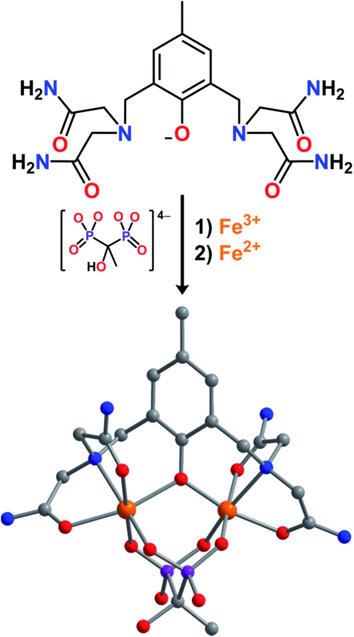
Fig. 1. Reaction of L–, etidronate tetraanion, Fe3+, and Fe2+ to form LFe2(etidronate), as observed in LFe2(etidronate)·7H2O. Orange, purple, blue, red, and gray spheres represent Fe, P, N, O, and C atoms, respectively; H atoms are omitted for clarity.
Results and discussion
The synthesis of the anionic complex [LFe2(etidronate)]– was carried out through successive additions of two equivalents of [Fe(H2O)6]2+ and one equivalent of etidronic acid, in the presence of NMe4OH, to a solution of HL in methanol, to give the compound (NMe4)[LFeII2(etidronate)]·2.7H2O·THF (1) as a light yellow solid. The analogous mixed-valence FeIIFeIII and univalence FeIII2 complexes were prepared similarly, but with 1 : 1 [Fe(H2O)6]2+ : [Fe(H2O)6]3+ and exclusively [Fe(H2O)6]3+, respectively, to afford the red compounds LFe2(etidronate)·0.7H2O·0.2THF (2) and [LFe2(etidronate)](NO3)·0.9H2O·1.5THF (3). The ancillary ligand etidronate improves the aqueous solubility of the neutral molecule LFe2(etidronate) relative to pyrophosphate, which was employed in the Cu2 analogue.14
Slow diffusion of THF vapor into a concentrated solution of 2 in H2O afforded plate-shaped single crystals of LFe2(etidronate)·H2O that were suitable for X-ray structural analysis. The structure features two distinct Fe centers, each in a distorted octahedral coordination environment comprising two carboxamide O atoms, one μ-phenoxo O atom, and one N atom from L–, along with two O atoms from a μ2–κ4 etidronate bridging ligand (see Fig. 1). The mean Fe–O bond distances for the two Fe centers are distinct at 1.992(5) and 2.125(6) Å, indicative of valence-localized high-spin FeIII and FeII, respectively. The Fe–OL–Fe angle of 118.6(3)° and Fe···Fe distance of 3.547(2) Å are consistent with related mixed-valence Fe2 complexes.15
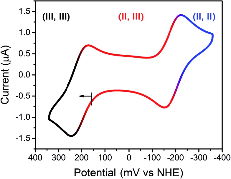
To probe the redox chemistry of the Fe2 complex, a cyclic voltammogram was collected for an aqueous solution of 2 in HEPES buffer at pH 7.4. The voltammogram features two reversible processes at potentials of E 1/2 = –187 and 209 mV vs. the Normal Hydrogen Electrode (NHE) (see Fig. 2). These processes are assigned to the FeIIFeII/FeIIFeIII and FeIIFeIII/FeIIIFeIII couples, respectively. The potential separation of ΔE 1/2 = 396 mV corresponds to a comproportionation constant of K c = 5.00 × 10⁶ for the reaction [LFe2(etidronate)]+ + [LFe2(etidronate)]– → 2LFe2(etidronate), indicating that the mixed-valence complex is stable towards disproportionation. Similarly, a solution of 1 gave an identical voltammogram, albeit with a different open-circuit potential (see Fig. S1†). Importantly, the redox window observed here is wide and biologically relevant, consistent with the electrochemical potentials of intra- and extracellular environments, spanning from –300 to 0 mV vs. NHE.12g Further, note that the broad library of bisphosphonate ligands offers the possibility to tune the potential window to target specific redox environments.
Fig. 2. Cyclic voltammogram of 2 in solution containing 100 mM NaCl, 100 mM HEPES buffered at pH 7.4; scan rate = 50 mV s–1. Roman numerals represent Fe oxidation states.
Mössbauer spectra were collected to investigate the nature of mixed-valency in 2. At 80 K, the compound displays two quadrupole doublets with isomer shifts of δ = 1.23(1) and 0.480(5) mm s–1 and quadrupole splittings of ΔE Q = 2.65(2) and 0.485(8) mm s–1, that we respectively assign to high-spin FeII and high-spin FeIII (see Fig. S2†).16 The areal ratio between the two spectral components of 1 : 1.1(1) indicates a valence-trapped FeIIFeIII electronic structure, in agreement with crystallographic analysis.17 In contrast, the spectrum for 1 at 80 K is best modeled with two doublets (δ = 1.325(8) and 1.158(7) mm s–1, ΔE Q = 2.871(7) and 2.874(6) mm s–1) that correspond to two similar but inequivalent high-spin FeII centers (see Fig. S3†).
A solution of 2 in neutral D2O exhibits features at 21,277 cm–1 (ε = 861 M–1 cm–1) and 7318 cm–1 (ε = 83 M–1 cm–1) (see Fig. S4†), which we assign to ligand-to-metal charge-transfer (LMCT) and intervalence charge transfer (IVCT) bands, respectively, in accord with similar mixed-valence Fe2 complexes.18 Polar solvents often forestall electron transfer, and as such, the observation of IVCT in D2O is notable and highlights the stability and rigidity of the Fe2 complex. The IVCT full-width at half-maximum of Δν 1/2 = 3043 cm–1 is lower than the theoretical linewidth of Δν01/2 = (2310(ν max))1/2 = 4112 cm–1, suggesting some degree of electron detrapping in 2.19 Moreover, a linewidth analysis using the crystallographic Fe···Fe distance provides an estimate of the 298 K electron transfer rate as 6.7(1) × 1010 s–1 (see ESI† for details).16a,20 The solution spectrum closely resembles that of the solid-state diffuse reflectance (see Fig. S5†), suggesting that the crystallographic structure is retained in solution. In contrast to 2, only a shoulder at 22,000 cm–1 (ε = 48 M–1 cm–1) is present in the spectrum for 1 (see Fig. S4†). This observation is consistent with a univalence FeII2 configuration and agrees with literature examples.21
To assess magnetic interactions in the Fe2 complexes, variable-temperature magnetic susceptibility measurements were carried out for solid-state samples of 1 and 2 (see Fig. S6†). At 300 K, χ M T = 7.17 cm3 K mol–1 for 1, consistent with two non-interacting high-spin FeII centers. For 2, χ M T = 6.87 cm3 K mol–1 at 300 K, consistent with high-spin FeIII and FeII. For both compounds, χ M T decreases with decreasing temperature, albeit more rapidly for 2, indicative of antiferromagnetic superexchange. These interactions were modeled with the spin Hamiltonian Ĥ = –2J(ŝ Fe1·ŝ Fe2),22 to give exchange coupling constants J = –0.8(3) cm–1 for 1 and J = –3.6(5) cm–1 for 2. The stronger coupling in 2 is likely due to the shorter FeIII–O bond relative to the FeII–O bond in 1. These values are comparable to those previously reported for structurally-similar Fe2 complexes.15 Solution magnetic moments for 1, 2 and 3 were measured as χ M T = 7.3(3), 7.0(6) and 8.9(3) cm3 K mol–1 at 310 K, respectively, consistent with the solid-state magnetic data and the presence of exclusively high-spin FeII and FeIII. The larger than expected χ M T for 1 is likely due to the anisotropic FeII, as evidenced by the g value (see magnetic experimental section in ESI†).
Neutral aqueous solutions of 1 and 2 gave sharp, well-resolved 1H NMR spectra. The spectrum for 1 features 20 paramagnetically shifted resonances that range from –50 to 150 ppm (see Fig. S7†), with exchangeable protons appearing at –9.5, 8.5, 29, 40 and 68 ppm established by comparing the spectra obtained in D2O and H2O. These five resonances are assigned to four structurally inequivalent carboxamide groups and the etidronate hydroxyl group. In comparison, 14 paramagnetically shifted resonances are present in the spectrum for 2, ranging from –10 to 320 ppm (see Fig. S8†). The resonances at 74 and 83 ppm are assigned to exchangeable protons on the carboxamide groups, as evidenced by their disappearance in the presence of D2O. The full width at half maximum for the resonances of 1 and 2 are 65–820 Hz and 44–620 Hz, respectively. The similarity in linewidth suggests that the smaller number of observed paramagnetic resonances in 2 relative to 1 likely arises from peak-averaging caused by a fast electron transfer rate of 6.7(1) × 1010 s–1, rather than from peak-broadening caused by nuclear relaxation. Furthermore, spin-lattice relaxation times (T 1) for H2O, in samples containing 4.9 mM of 1 or 2 buffered at pH 7.4, are 1.30(1) and 1.14(1) s, respectively. The similar resonance linewidth and T 1 profiles suggest a shortening of τ s in FeIII, which otherwise would have imposed significant nuclear relaxation and thus severe line broadening. Such shortening of τ s is likely due to the magnetic coupling to a fast-relaxing FeII,12 as well as fast electron-transfer between the two Fe centers. In sum, the significantly different but sharp carboxamide resonances in 1 and 2 suggests the possibility to observe the CEST effect for the Fe2 probe in both oxidation states.
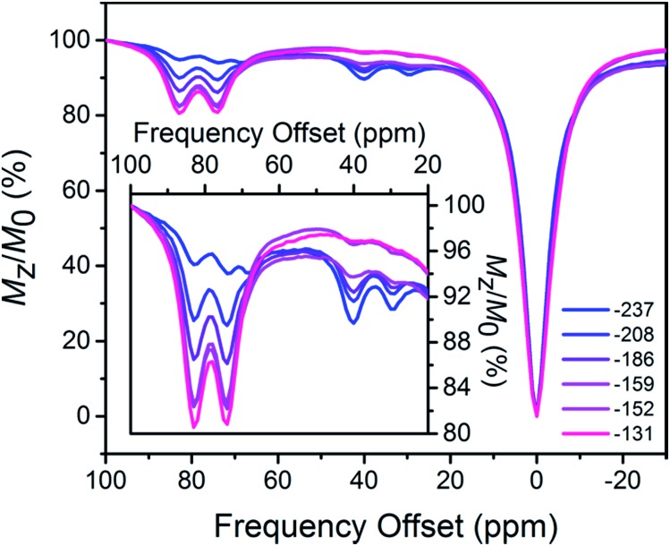
To investigate the possibility of CEST, 1H NMR spectra were collected for aqueous 3.4 mM solutions of 1 or 2 with 100 mM HEPES and 100 mM NaCl buffered at pH 7.4, using presaturation at frequencies ranging from –100 to 100 ppm referenced to H2O. The CEST spectrum, or Z-spectrum, shows the extent of H2O signal intensity reduction with respect to the saturation frequency, or frequency offset. In the spectrum for 1, three CEST peaks appear at 29, 40 and 68 ppm with 8.8, 10 and <5% H2O signal reduction, respectively (see Fig. S9, top†). Note that any CEST effect stemming from the two upfield labile protons at –9.5 and 8.5 ppm are likely masked by direct saturation of H2O. In comparison, two CEST peaks are present in the CEST spectrum for 2, centered at 74 and 83 ppm with 21 and 22% H2O signal reduction, respectively (see Fig. S9, bottom†). Using the omega plot method,23 the proton exchange rates were estimated as 6.5(8) × 102 (29 ppm) and 5.0(8) × 102 (40 ppm) s–1 for 1, and 6.8(9) × 102 (74 ppm) and 7.0(8) × 102 (83 ppm) s–1 for 2, respectively (see Fig. S10 and S11†), in agreement with rates reported in mononuclear FeII carboxamide PARACEST agents.24 Most importantly, the orthogonality of CEST peaks for 1 and 2 suggests the possibility for ratiometric measurements.
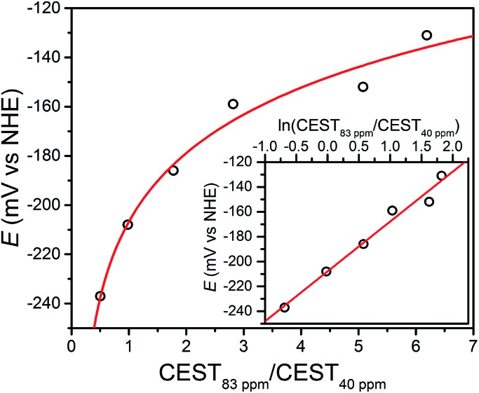
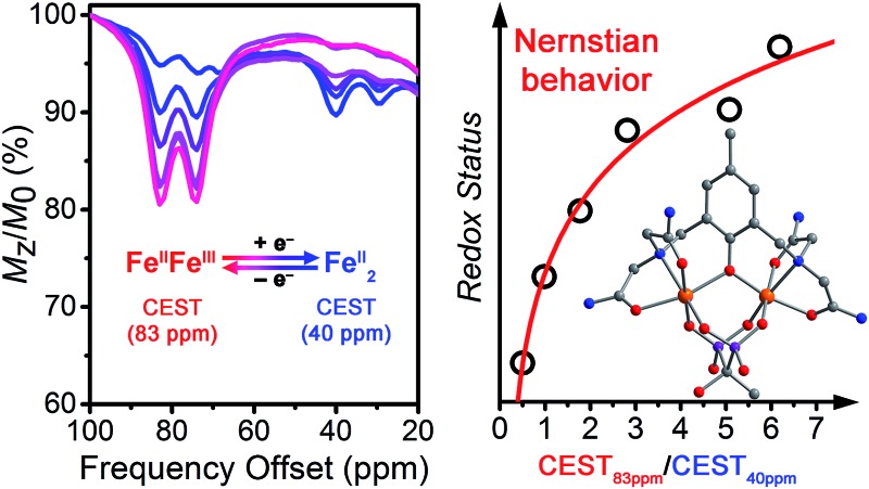
The open-circuit potential (OCP) of an electrochemical cell provides an experimental measure of the reducing or oxidizing nature of the solution environment. For a system at equilibrium, the OCP represents a collective measure of the ratio between the oxidized and reduced forms of each redox-active species and follows the Nernst equation. Therefore, we constructed a ratiometric calibration curve over a range of OCPs centered around the FeIIFeII/FeIIFeIII redox couple. Specifically, we collected CEST spectra for a series of solutions containing 100 mM HEPES, 100 mM NaCl, and selected ratios of 1 : 2 (total [Fe2] = 4.9 mM) in the range 9 : 1 to 1 : 9, and then correlated these spectral ratios to OCPs obtained independently using a potentiostat (see Fig. 3). Importantly, note that the OCP values stabilized within a variation of <1 mV after seconds, suggesting relatively fast kinetics toward reaching equilibrium (see Fig. S12–S15†). As the OCP becomes more reducing (i.e. a higher fraction of 1), the CEST intensity at 74 and 83 ppm monotonically decreases with a concomitant increase in intensity at 29 and 40 ppm. To construct a calibration curve, the ratio of % CEST effect at 83 and 40 ppm (CEST83 ppm/CEST40 ppm) was plotted as a function of OCP (see Fig. 4). The corresponding data follow Nernstian behavior, and can therefore be fit to the following equation where OCP varies linearly with the semilog of CEST83 ppm/CEST40 ppm:
| OCP (mV) = 40.1 ln(CEST83 ppm/CEST40 ppm) – 208 | 1 |
Fig. 3. CEST spectra collected at 37 °C for 4.9 mM aqueous solutions of 1 and 2 at pH 7.4, with ratios of 1 : 2 from 9 : 1 (blue) to 1 : 9 (red). The legend gives the independently obtained OCP of each sample (mV vs. NHE). Inset: expanded view of the relevant CEST peaks.
Fig. 4. Open-circuit potential (OCP) of aqueous Fe2 samples vs. ratios of CEST peak intensities from presaturation at 83 and 40 ppm. Inset: semilog form of the plot. Black circles represent experimental data; red lines represent fits.
The effectiveness of eqn (1) to quantitate OCP in the presence of potassium superoxide and cysteine was examined. First, a solution containing 4 mM of 1 was incubated with 1 mM of KO2 in pH 7.4 buffer. The resulting CEST spectrum exhibits peaks at 74 and 83 ppm, in addition to those from 1, arising from the oxidation product LFe2(etidronate) (see Fig. S16†). The % CEST at 83 and 40 ppm is 7.1 and 5.3, respectively, resulting in a calculated OCP of –219 mV based on eqn (1), which is in excellent agreement with the experimentally determined OCP of –225 mV. In another sample, 4 mM of 2 was incubated with 200 mM of cysteine in pH 7.4 buffer. The calculated OCP based on % CEST at 83 and 40 ppm and eqn (1) was –187 mV, which is in good agreement with the experimental OCP of –204 mV (see Fig. S17†). Both reactions exhibit reasonably fast kinetics, with the KO2 oxidation reaching equilibrium in 10 minutes and the cysteine reduction in 50 minutes, as evidenced by the temporal stabilization of OCP (see Fig. S18†). These experiments demonstrate the responsiveness of the Fe2 probe towards thiol and superoxide, as well as the ability of eqn (1) to quantitate solution OCP dictated by thiol-based reductants and reactive oxygen species-based oxidants.
We next sought to determine how factors such as pH and temperature affect this calibration curve, as these factors exhibit slight heterogeneity in physiological conditions. Most notably, pH affects the exchange rate of CEST-active protons, which leads to changes in CEST peak intensities. However, such changes can be partially compensated by taking the ratio of two CEST peaks in the event that both are altered to similar degree. To investigate pH effects, two series of solutions, buffered at pH 7.3 and 7.5, respectively, were prepared analogously to those at pH 7.4. Fits of the obtained OCPs as a function of CEST83 ppm/CEST40 ppm for the two series gave the following two Nernstian equations (see Fig. S19–S22†):
| pH 7.3: OCP (mV) = 36.4 ln(CEST83 ppm/CEST40 ppm) – 218 | 2 |
| pH 7.5: OCP (mV) = 41.5 ln(CEST83 ppm/CEST40 ppm) – 216 | 3 |
Eqn (1)–(3) are summarized in Fig. S23.† For a given ln(CEST83 ppm/CEST40 ppm) value, the maximum deviation in OCP over the entire range of potentials was found to be ca. 20 mV. This value represents the maximum expected error introduced into the calibration curve by pH inhomogeneity of 7.3–7.5.
In addition to pH, temperature can also alter the intensity and frequency offset of the CEST peak, owing to increased proton exchange rate and the temperature dependence of hyperfine shift.12 To investigate effects from temperature variation, the data collected at pH 7.5, which feature slightly more significant CEST effects due to base-catalyzed proton exchange mechanism, were examined at 35 and 39 °C, respectively. Note that the CEST peak at 83 ppm at 37 °C shifted to 84 and 82 ppm at 35 and 39 °C, respectively, while the variable-temperature shift in the CEST peak at 40 ppm was insignificant (see Fig. S24–S27†). Fits of the OCP vs. CEST83 ppm/CEST40 ppm plots for data obtained at 35 and 39 °C gave the following two Nernstian equations (see Fig. S24–S27†):
| 35 °C: OCP (mV) = 59.9 ln(CEST83 ppm/CEST40 ppm) – 246 | 4 |
| 39 °C: OCP (mV) = 48.6 ln(CEST83 ppm/CEST40 ppm) – 211 | 5 |
Using the same analysis used in the pH series, for a given ln(CEST83 ppm/CEST40 ppm) value, the largest deviation in the OCP readout was found to be ca. 40 mV (see Fig. S28†).
The kinetic and thermodynamic properties of 1 and 2 towards ions, air and reductants were examined by comparison of electronic absorption and NMR spectra. In the presence of 4 mM solutions of the ions H2PO4 –/HPO4 2–, CO3 2–, SO4 2–, CH3COO–, or Ca2+, incubated at 37 °C for 12 h, 4 mM of 1 or 2 in solutions buffered at pH 7.4 or D2O show identical NMR spectra to solutions containing the respective Fe2 complex with no added ions (see Fig. S29–S36†). The experiments demonstrate the high stability of the Fe2 complexes towards physiological ions of millimolar concentrations.25 Finally, the observation of CEST arising from 1 and 2 was confirmed in bovine blood plasma (see Fig. S37†). While the baseline is broader than in the spectra obtained in buffer solution, presumably due to the presence of additional exchangeable protons from proteins in the plasma, the CEST peaks from 1 and 2 can be unambiguously observed and are comparable to those obtained in buffers.
While ions do not introduce interference to the stability of 1 and 2, the FeIIFeIII/FeIIIFeIII redox couple (209 mV vs. NHE) makes oxidation of 2 in air a concern, which was studied by electronic absorption spectroscopy. A solution buffered at pH 7.4 containing 0.4 mM of 2 was prepared in a nitrogen glove box and exposed to air while a UV-Vis-NIR spectrum was recorded at 2 h intervals (see Fig. S38,† bottom). Over the course of 40 h, the absorption at 801 nm gradually disappeared, while the absorption at 470 nm shifted to ca. 460 nm and decreased in intensity. These spectral changes proceed through an isosbestic point at 445 nm, suggesting a clean conversion to a single, new species. Indeed, a similarly buffered solution containing 0.4 mM of 3 showed an identical UV-Vis-NIR spectrum to that of the 40 h oxidation product of 2 (see Fig. S38†), demonstrating that 2 is cleanly oxidized to the stable 3 in air. Moreover, the reversibility of this oxidation was demonstrated by in situ reduction of 3 by glutathione, as monitored by NMR spectroscopy (see Fig. S39 and S40†). This redox reversibility suggests the potential utilization of 3 as a probe precursor, which is stable in air and could undergo reduction to the CEST-active FeIIFeIII upon introduction into the reducing extracellular environment of tissue.
To further examine the possibility of using 3 as a probe precursor, we carried out preliminary cell viability experiments using melanoma B16F10 cells as a model. After incubating the cells with media containing various concentrations of 3, the percentages of viable cells were recorded (see Fig. S41†). In the presence of 8.2 mM of 3, ca. 80% of cells are viable, and this percentage increased up to ca. 90% for samples containing lower concentrations of 3. Overall >80% viability within millimolar probe concentration range is quite promising, as this is the concentration in which PARACEST probes show optimal contrast.
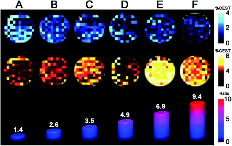
Finally, we sought to investigate whether the favorable CEST properties of the Fe2 probe observed on a 9.4 T NMR spectrometer could also be realized on phantom images from a 9.4 T preclinical MRI scanner. A series of solutions containing overall 10 mM Fe2 with 1 : 2 ratio ranging from 9 : 1 to 1 : 9 were prepared similarly to those in the NMR study. For each sample, two images were acquired with a 14 μT presaturation pulse applied at frequencies of 40 and 83 ppm from the H2O signal (see Fig. 5). Control images were acquired at the respective presaturation frequencies with 0 μT power. Presaturation at 40 and 83 ppm reduced the H2O intensity up to ca. 4 and 8%, respectively, demonstrating that CEST effects from both FeII2 and FeIIFeIII redox states can be observed on a MRI scanner. However, the inhomogeneity of phantom intensities, likely stemming from weak CEST effects and therefore a noisy background, makes the contrast across phantoms virtually indistinguishable. Despite the ambiguous visualization of trend in redox status, the OCPs independently measured by a potentiostat can be plotted against the ratios between averaged phantom intensities from 83 and 40 ppm (CEST83 ppm/CEST 40 ppm) to give a Nernstian fit resembling eqn (1)–(5) (see Fig. S42†). Furthermore, the OCPs calculated from the calibration, using intensities from phantom, fall in relatively good agreement with the OCPs measured by a potentiostat (see Table 1). Future efforts will aim to improve homogeneity of phantom images by increasing CEST through combination of chemical and pulse sequence optimizations.
Fig. 5. Phantom images of solutions containing 10 mM of Fe2 with 1 : 2 ratios ranging from 9 : 1 to 1 : 9 (A–F). Top and middle rows of images represent CEST effects with 14 μT presaturation at 40 and 83 ppm, respectively. The bars along the bottom row represent the ratio of average % CEST for presaturation at 83 and 40 ppm.
Table 1. Comparison of OCP values obtained by Nernstian equation from CEST imaging vs. those obtained by potentiostat.
| OCP (vs. NHE) | A | B | C | D | E | F |
| CEST imaging | –263 | –213 | –188 | –161 | –133 | –107 |
| Potentiostat | –222 | –201 | –188 | –170 | –135 | –101 |
Conclusions
The foregoing results demonstrate the feasibility of using the Nernst equation to correlate OCP with the ratio of CEST effects from a Fe2 PARACEST probe, in a range spanning ca. –120 to –230 mV vs. NHE. To our knowledge, this study provides the first demonstration of ratiometric quantitation of solution redox status through NMR/MRI measurables. The CEST-active mixed-valence compound 2 is enabled by the presence of fast electron transfer and magnetic coupling to the neighboring fast-relaxing FeII center, as evidenced by NMR and electronic absorption studies. The potential applicability of the Fe2 probe is further highlighted by the potential utilization of the air-stable [FeIII2]+ complex as a one-electron oxidized probe precursor, which shows low cell-toxicity and excellent redox reversibility. Finally, a Nernstian calibration curve was constructed using averaged CEST effects from phantom images, and OCPs obtained from this curve are in good agreement with those obtained from a potentiostat.
Whereas the current Fe2 probe provides a promising proof-of-concept for quantitation of redox status, perhaps most exciting is that the dinucleating ligand scaffold provides an excellent platform for chemically tuning the FeIIFeII/FeIIFeIII redox couple. Toward this end, preliminary experiments show that the FeIIFeII/FeIIFeIII redox couple can be varied over a 120 mV range through either introduction of other bisphosphonate derivatives or chemical modification of the dinucleating ligand. Current work is geared toward tailoring members of this family of molecules to target optimal redox properties and proton exchange properties for in vivo applications.
Acknowledgments
This research was funded by the Air Force Research laboratory under agreement number FA8650-15-5518, the Chemistry of Life Processes Institute, and Northwestern University. T. D. H. thanks the Alfred P. Sloan Foundation. The U. S. Government is authorized to reproduce and distribute reprints for governmental purposes notwithstanding any copyright notation thereon. The views and conclusions contained herein are those of the authors and should not be interpreted as necessarily representing the official policies or endorsements, either expressed or implied, of AFRL or the U. S. Government. We thank Drs J. M. Zadrozny and L. Liu for helpful discussions, Ms. A. T. Gallagher and Mr J. A. DeGayner for experimental assistance, and Prof. T. J. Meade for generous donation of B16F10 cell supplies and use of his HPLC system and laminar flow hood.
Footnotes
References
- (a) Redox in Biochemistry, ed. R. Banerjee, John Wiley & Sons, Hoboken, 2008. [Google Scholar]; (b) Chaiswing L., Oberley T. D. Antioxid. Redox Signaling. 2010;13:449. doi: 10.1089/ars.2009.3020. [DOI] [PubMed] [Google Scholar]; (c) Banerjee R. J. Biol. Chem. 2012;287:4397. doi: 10.1074/jbc.R111.287995. [DOI] [PMC free article] [PubMed] [Google Scholar]
- (a) Jones D. P., Carlson J. L., Mody Jr V. C., Cai J., Lynn M. J., Sternberg Jr P. Free Radical Biol. Med. 2000;28:625. doi: 10.1016/s0891-5849(99)00275-0. [DOI] [PubMed] [Google Scholar]; (b) Go Y.-M., Jones D. P. Methods Enzymol. 2010;474:165. doi: 10.1016/S0076-6879(10)74010-6. [DOI] [PMC free article] [PubMed] [Google Scholar]
- Lou Z., Li P., Han K. Acc. Chem. Res. 2015;48:1358. doi: 10.1021/acs.accounts.5b00009. [DOI] [PubMed] [Google Scholar]
- Selected examples: ; (a) Jiang S., Moriarty-Craige S. E., Orr M., Cai J., Sternberg Jr P., Jones D. P. Invest. Ophthalmol. Visual Sci. 2005;46:1054. doi: 10.1167/iovs.04-0949. [DOI] [PubMed] [Google Scholar]; (b) Chaiswing L., Zhong W., Cullen J. J., Oberley L. W., Oberley T. D. Cancer Res. 2008;68:5820. doi: 10.1158/0008-5472.CAN-08-0162. [DOI] [PubMed] [Google Scholar]; (c) Chaiswing L., Zhong W., Liang Y., Jones D. P., Oberley T. D. Free Radical Biol. Med. 2012;52:452. doi: 10.1016/j.freeradbiomed.2011.10.489. [DOI] [PMC free article] [PubMed] [Google Scholar]; (d) Iyer S. S., Ramirez A. M., Ritzenthaler J. D., Torres-Gonzalez E., Roser-Page S., Mora A. L., Brigham K. L., Jones D. P., Roman J., Rojas M. Am. J. Physiol.: Lung Cell. Mol. Physiol. 2009;296:37. doi: 10.1152/ajplung.90401.2008. [DOI] [PMC free article] [PubMed] [Google Scholar]
- Wang B., Li P., Yu F., Chen J., Qu Z., Han K. Chem. Commun. 2013;49:5790. doi: 10.1039/c3cc42313a. [DOI] [PubMed] [Google Scholar]
- (a) Lauffer R. B. Chem. Rev. 1987;87:901. [Google Scholar]; (b) Caravan P., Ellison J. J., McMurry T. J., Lauffer R. B. Chem. Rev. 1999;99:2293. doi: 10.1021/cr980440x. [DOI] [PubMed] [Google Scholar]; (c) Caravan P. Chem. Soc. Rev. 2006;35:512. doi: 10.1039/b510982p. [DOI] [PubMed] [Google Scholar]
- (a) Aime S., Botta M., Gianolio E., Terreno E. Angew. Chem., Int. Ed. 2000;39:747. doi: 10.1002/(sici)1521-3773(20000218)39:4<747::aid-anie747>3.0.co;2-2. [DOI] [PubMed] [Google Scholar]; (b) Krohn K. A., Link J. M., Mason R. P. J. Nucl. Med. 2008;49:129S. doi: 10.2967/jnumed.107.045914. [DOI] [PubMed] [Google Scholar]; (c) Tsitovich P. B., Spernyak J. A., Morrow J. R. Angew. Chem., Int. Ed. 2013;52:13997. doi: 10.1002/anie.201306394. [DOI] [PMC free article] [PubMed] [Google Scholar]; (d) Ekanger L. A., Polin L. A., Shen Y., Haacke E. M., Martin P. D., Allen M. J. Angew. Chem., Int. Ed. 2015;54:14398. doi: 10.1002/anie.201507227. [DOI] [PMC free article] [PubMed] [Google Scholar]; (e) Xie D., King T. L., Banerjee A., Kohli V., Que E. L. J. Am. Chem. Soc. 2016;138:2937. doi: 10.1021/jacs.5b13215. [DOI] [PubMed] [Google Scholar]
- Yu M., Ambrose S. L., Whaley Z. L., Fan S., Gorden J. D., Beyers R. J., Schwartz D. D., Goldsmith C. R. J. Am. Chem. Soc. 2014;136:12836. doi: 10.1021/ja507034d. [DOI] [PubMed] [Google Scholar]
- (a) Jagadish B., Guntle G. P., Zhao D., Gokhale V., Ozumerzifon T. J., Ahad A. M., Mash E. A., Raghunand N. J. Med. Chem. 2012;55:10378. doi: 10.1021/jm300736f. [DOI] [PMC free article] [PubMed] [Google Scholar]; (b) Loving G. S., Mukherjee S., Caravan P. J. Am. Chem. Soc. 2013;135:4620. doi: 10.1021/ja312610j. [DOI] [PMC free article] [PubMed] [Google Scholar]
- Ratnakar S. J., Viswanathan S., Kovacs Z., Jindal A. K., Green K. N., Sherry A. D. J. Am. Chem. Soc. 2012;134:5798. doi: 10.1021/ja211601k. [DOI] [PMC free article] [PubMed] [Google Scholar]
- Que E. L., Chang C. J. Chem. Soc. Rev. 2010;39:51. doi: 10.1039/b914348n. [DOI] [PubMed] [Google Scholar]
- (a) Zhang S., Winter P., Wu K., Sherry A. D. J. Am. Chem. Soc. 2001;123:1517. doi: 10.1021/ja005820q. [DOI] [PubMed] [Google Scholar]; (b) Zhang S., Merritt M., Woessner D. E., Lenkinski R. E., Sherry A. D. Acc. Chem. Res. 2003;36:783. doi: 10.1021/ar020228m. [DOI] [PubMed] [Google Scholar]; (c) Zhou J., van Zijl P. C. M. Prog. Nucl. Magn. Reson. Spectrosc. 2006;48:109. [Google Scholar]; (d) Ali M. M., Liu G., Shah T., Flask C. A., Pagel M. D. Acc. Chem. Res. 2009;42:915. doi: 10.1021/ar8002738. [DOI] [PMC free article] [PubMed] [Google Scholar]; (e) Viswanathan S., Kovacs Z., Green K. N., Ratnakar S. J., Sherry A. D. Chem. Rev. 2010;110:2960. doi: 10.1021/cr900284a. [DOI] [PMC free article] [PubMed] [Google Scholar]; (f) Terreno E., Castelli D. D., Viale A., Aime S. Chem. Rev. 2010;110:3019. doi: 10.1021/cr100025t. [DOI] [PubMed] [Google Scholar]; (g) Tsitovich P. B., Burns P. J., McKay A. M., Morrow J. R. J. Inorg. Biochem. 2014;133:143. doi: 10.1016/j.jinorgbio.2014.01.016. [DOI] [PubMed] [Google Scholar]
- (a) Bertini I. and Luchinat C., NMR of Paramagnetic Molecules in Biological Systems, The Benjamin/Cummings Publishing Company, Inc., Menlo Park, 1986. [Google Scholar]; (b) Bertini I., Luchinat C. Coord. Chem. Rev. 1996;150:1. [Google Scholar]; (c) Bertini I., Luchinat C. and Parigi G., Solution NMR of Paramagnetic Molecules: Applications to Metallobiomolecules and Models; Elsevier Science B. V., Amsterdam, 2001. [Google Scholar]
- Du K., Harris T. D. J. Am. Chem. Soc. 2016;138:7804. doi: 10.1021/jacs.6b03060. [DOI] [PubMed] [Google Scholar]
- Mashuta M. S., Webb R. J., Oberhausen K. J., Richardson J. F., Buchanan R. M., Hendrickson D. N. J. Am. Chem. Soc. 1989;111:2745. [Google Scholar]
- (a) Borovik A. S., Papaefthymiou V., Taylor L. F., Anderson O. P., Que Jr L. J. Am. Chem. Soc. 1989;111:6183. [Google Scholar]; (b) Lambert E., Chabut B., Chardon-Noblat S., Deronzier A., Chottard G., Bousseksou A., Tuchagues J.-P., Laugier J., Bardet M., Latour J.-M. J. Am. Chem. Soc. 1997;119:9424. [Google Scholar]; (c) Gouré E., Carboni M., Troussier A., Lebrun C., Pécaut J., Jacquot J.-F., Dubourdeaux P., Clémancey M., Blondin G., Latour J.-M. Chem.–Eur. J. 2015;21:8064. doi: 10.1002/chem.201500977. [DOI] [PubMed] [Google Scholar]; (d) Mashuta M., Webb R. J., McCusker J. K., Schmitt E. A., Oberhausen K. J., Richardson J. F., Buchanan R. M., Hendrickson D. N. J. Am. Chem. Soc. 1992;114:3815. [Google Scholar]
- Fultz B., Characterization of Material, ed. E. Kaufmann, John Wiley, New York, 2011, pp. 1–21. [Google Scholar]
- Borovik A. S., Que Jr L. J. Am. Chem. Soc. 1988;110:2345. [Google Scholar]
- Hush N. S. Prog. Inorg. Chem. 1967;8:391. [Google Scholar]
- (a) Kestner N. R., Logan J., Jortner J. J. Phys. Chem. 1974;78:2148. [Google Scholar]; (b) Hopfield J. J. Proc. Natl. Acad. Sci. U. S. A. 1974;71:3640. doi: 10.1073/pnas.71.9.3640. [DOI] [PMC free article] [PubMed] [Google Scholar]; (c) Meyer T. J. Chem. Phys. Lett. 1979;64:417. [Google Scholar]
- Murch B. P., Bradley F. C., Que Jr L. J. Am. Chem. Soc. 1986;108:5027. [Google Scholar]
- (a) Magnetic susceptibility data were simulated using the program MagProp: Tregenna-Piggott P. L. W., MagProp (part of the NIST DAVE software suite), version 2.0, 2008, http://www.ncnr.nist.gov/dave.; (b) Azuah R. T., Kneller L. R., Qiu Y. M., Tregenna-Piggott P. L. W., Brown C. M., Copley J. R. D., Dimeoo R. M. J. Res. Natl. Inst. Stand. Technol. 2009;114:341. doi: 10.6028/jres.114.025. [DOI] [PMC free article] [PubMed] [Google Scholar]
- Dixon W. T., Ren J., Lubag A. J. M., Ratnakar J., Vinogradov E., Hancu I., Lenkinski R. E., Sherry A. D. Magn. Reson. Med. 2010;63:625. doi: 10.1002/mrm.22242. [DOI] [PMC free article] [PubMed] [Google Scholar]
- (a) Tsitovich P. B., Morrow J. R. Inorg. Chim. Acta. 2012;393:3. [Google Scholar]; (b) Dorazio S. J., Morrow J. R. Inorg. Chem. 2012;51:7448. doi: 10.1021/ic301001u. [DOI] [PubMed] [Google Scholar]; (c) Olatunde A. O., Bond C. J., Dorazio S. J., Cox J. M., Benedict J. B., Daddario M. D., Spernyak J. A., Morrow J. R. Chem.–Eur. J. 2015;21:18290. doi: 10.1002/chem.201503125. [DOI] [PMC free article] [PubMed] [Google Scholar]
- Wan Q. J., Kubáň P., Tanyanyiwa J., Rainelli A., Hauser P. C. Anal. Chim. Acta. 2004;525:11. [Google Scholar]
Associated Data
This section collects any data citations, data availability statements, or supplementary materials included in this article.


