

Abstract
Three-dimensional porous scaffolds play a pivotal role in tissue engineering and regenerative medicine by functioning as biomimetic substrates to manipulate cellular behaviors. While many techniques have been developed to fabricate porous scaffolds, most of them rely on stochastic processes that typically result in scaffolds with pores uncontrolled in terms of size, structure, and interconnectivity, greatly limiting their use in tissue regeneration. Inverse opal scaffolds, in contrast, possess uniform pores inheriting from the template comprised of a closely packed lattice of monodispersed microspheres. The key parameters of such scaffolds, including architecture, pore structure, porosity, and interconnectivity, can all be made uniform across the same sample and among different samples. In conjunction with a tight control over pore sizes, inverse opal scaffolds have found widespread use in biomedical applications. In this review, we provide a detailed discussion on this new class of advanced materials. After a brief introduction to their history and fabrication, we highlight the unique advantages of inverse opal scaffolds over their non-uniform counterparts. We then showcase their broad applications in tissue engineering and regenerative medicine, followed by a summary and perspective on future directions.
Keywords: inverse opals, porous scaffolds, biomaterials, tissue engineering, regenerative medicine
1. Introduction
Tissue engineering and regenerative medicine seek to generate tissue substitutes via biomimetic approaches through a combination of cells, biomolecules, and advanced materials.[1] The materials, typically referred to as scaffolds, serve as biomimetic matrices for cells to reside in and respond to, ultimately facilitating the formation of tissues.[2,3-5] Ideally, a scaffold should be engineered to possess a set of parameters and an amenable microenvironment for cells to interact with. For example, three-dimensionality is required for engineering most types of tissues where multiple layers of complex patterns are present.[6,7] The mechanical strength should match that of the target tissue, which is particularly important for stem cells as their differentiation is sensitive to substrate stiffness.[8] Adhesion molecules also need to be incorporated into or coated onto the surface of a scaffold to improve their interactions with cells.[9,10] Growth factors or nucleic acids may be encapsulated into the scaffold and released in a controlled manner to promote tissue development and maturation via biochemical cues.[10,11] The last but not least, the scaffold should be biocompatible and biodegradable so it will be absorbed at a rate proportional to that of tissue regeneration for the achievement of a complete integration with the host.[12]
Among different types of three-dimensional (3D) scaffolds, those with properly sized, interconnected pores are highly preferred as they would provide the seeded cells with a sufficient surface area to adhere to, together with a well-connected space for the cells to proliferate and migrate during the regeneration of tissues.[3,4,7] The interconnectivity also ensures the efficient diffusion of oxygen, nutrients, and waste products, which is critical to maintaining high viability for the tissue, particularly at the early stage when vasculogenesis/angiogenesis has not taken place. To this end, biomedical researchers have developed a number of methods for producing 3D porous scaffolds from a variety of biomaterials. Salt-leaching and gas-foaming represent two most commonly used methods for the fabrication of porous scaffolds.[13,14] In these approaches, the porogens, either in the solid (e.g., NaCl crystals) or gas (e.g., CO2) form, are embedded in the scaffolding material and removed later to generate pores. Depending on the size of the porogen, it is possible to modulate the size of the pores in the resultant scaffold. Similarly, lyophilization provides another simple way to generate 3D scaffolds with a porous structure.[14,15] However, these methods offer limited controllability toward the architecture and physical properties of the scaffolds as the resultant pores are typically stochastic in size and poorly defined in spatial arrangements. The polydispersity in pore size would further reduce the interconnectivity between the cavities. Even worse, the disordered structure is barely reproducible across different batches, greatly limiting their applications in tissue engineering.
Recently, the technological advancements in 3D printing have demonstrated an improved capability in producing scaffolds with well-defined structures that are highly reproducible across batches.[7,16] As an example, fused deposition modeling (FDM) can build 3D scaffolds based on the extrusion of a melted biomaterial in a spatially defined pattern,[17] whereas stereolithography (SLA) can readily create hydrogel matrices or polymer scaffolds with defined structures through photopolymerization.[18] Although these approaches are useful in the fabrication of 3D scaffolds, not every laboratory possesses such sophisticated instruments due to the relatively high costs. To address this dilemma, inverse opal scaffolds have emerged as a class of enabling scaffolds that are accessible to any laboratory capable of processing conventional materials. Originating from the concept of salt-leaching or gas-foaming but with an unprecedented control, inverse opal scaffolds are fabricated by templating against cubic close packed (ccp) lattices of monodispersed microspheres.[5,19-24] Owing to the monodispersity of the microspheres, the resulting scaffolds possess uniform pores and interconnecting windows across each sample, together with excellent reproducibility in their physical properties across different batches.[5,25] With the use of inverse opals, finally we can achieve a quantitative analysis and understanding of the tissue regeneration process. To this end, inverse opal scaffolds are ideal biomimetic substrates. Their highly tunable and precisely controlled properties will allow people to quantify the diffusion of biomacromolecules, distribution of cells, and differentiation of progenitor/stem cells. It is envisioned that this new class of advanced materials will cause paradigm shift in studying tissue engineering and regenerative medicine.
In this review article, we start by introducing the general history of inverse opals and their evolution into inverse opal scaffolds for biomedical applications, followed by a discussion on the fabrication and precise engineering of their properties. Next, we highlight their unique advantages by comparing the inverse opal scaffolds with their counterparts possessing non-uniform pores from the aspects related to the diffusion of biomacromolecules, as well as cell distribution and differentiation. We then move on to showcase the various applications of inverse opal scaffolds in tissue engineering and regenerative medicine reported over the past decade. Finally, we conclude this article by offering some perspectives on the challenges and future directions, including the commercial potential of these scaffolds.
2. Inverse Opal Scaffolds
2.1. A Brief Note on the History
Inverse opals, or inverted colloidal crystals, refer to a class of porous structures that possess an ordered array of uniform pores with dimensions on the nano- and micrometer scale.[26] They were initially developed in 1997 by Velev and co-workers, who packed polystyrene (PS) latex beads of 200–1000 nm in size into a ccp lattice (one size of beads for each lattice) and then replicated the structure through in situ gelation of silica from a precursor in the void spaces among the beads and selective removal of the template by calcination in air (Figure 1A).[27] Immediately following this work, a variety of inverse opals made from many different types of materials were reported. For example, the same group demonstrated the fabrication of an inverse opal made of Au by calcining colloidal crystals of PS beads infiltrated with Au nanoparticles.[28] By templating with PS beads and removing the template with toluene, our group fabricated polyurethane inverse opals (Figure 1B).[29,30] Stein and co-workers, on the other hand, reported the fabrication of inverse opals made of metal oxides and metals (Figure 1C) by infiltrating the void spaces among PS beads with nickel oxalate, followed by its conversion to NiO and Ni through calcination in air and under hydrogen gas, respectively.[31] Meanwhile, John and collaborators demonstrated the fabrication of photonic crystals with complete photonic bandgaps by growing silicon in the voids of a silica-based opal via chemical vapor deposition, followed by etching the template with HF (Figure 1D).[32] Such porous structures have been applied to a wide variety of applications in areas ranging from catalysis[33] to energy storage,[34] gas sorption,[35] sensing,[36] and photonics,[37] among others.[38]
Figure 1.
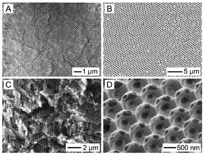
Early demonstrations of inverse opals with sub-micron pore sizes for applications in catalysis, sorption, chromatography, energy storage, and photonics. A) SiO2 inverse opal by Velev. Reproduced with permission.[27] Copyright 1997, Nature Publishing Group. B) Polyurethane inverse opal by Xia. Reproduced with permission.[30] Copyright 1998, Wiley-VCH. C) Ni inverse opal by Stein. Reproduced with permission.[31] Copyright 1999, Wiley-VCH. D) Si inverse opal by John. Reproduced with permission.[32] Copyright 2000, Nature Publishing Group.
Biomedical engineers appreciate the advantages of these well-defined porous structures as well. Replacing the backbones with biocompatible materials, the resulting porous structures provide a new class of scaffolds for engineering tissue substitutes. The first demonstrations were reported by the Ma group and the Ratner group, both in the early 2000s. The Ma group developed poly(L-lactic acid) (PLLA) inverse opal scaffolds using wax particles as the template (Figure 2A),[19] while poly(2-hydroxyethyl methacrylate) (PHEMA) inverse opal scaffolds were fabricated by the Ratner group through the selective removal of poly(methyl methacrylate) (PMMA) beads (Figure 2B).[20,39] Many other types of inverse opal scaffolds quickly ensued, including, for example, silica inverse opal scaffolds from the Kotov group (2004, Figure 2C),[21] poly(ethylene glycol) (PEG) inverse opal scaffolds from the Irvine group (2005, Figure 2D),[22] chitosan inverse opal scaffolds from our group (2009, Figure 2E),[23] and hydroxyapatite (HAp) inverse opal scaffolds from the Weng group (2011, Figure 2F).[40] It is important to point out that, to make these scaffolds suitable for biomedical applications, the pore sizes have to be pushed up to a length scale of tens to hundreds of micrometers to allow the seeded cells to spread, migrate, and function.
Figure 2.

Examples showing the expansion in pores size of inverse opal scaffolds for biomedical applications. A) PLLA inverse opal scaffold by Ma. Reproduced with permission.[19] Copyright 2001, Mary Ann Liebert. B) PHEMA inverse opal scaffold by Ratner. Reproduced with permission.[39] Copyright 2004, Annual Reviews. C) SiO2 inverse opal scaffold by Kotov. Reproduced with permission.[21] Copyright 2004, American Chemical Society. D) PEG inverse opal scaffold by Irvine. Reproduced with permission.[22a] Copyright 2005, Wiley-VCH. E) Chitosan inverse opal scaffold by Xia. Reproduced with permission.[23] Copyright 2009, Wiley-VCH. F) HAp inverse opal scaffold by Weng. Reproduced with permission.[40] Copyright 2011, Elsevier.
2.2. Precise Engineering of the Properties
As discussed above, the well-defined architecture and the uniform pore sizes of an inverse opal scaffold are inherited from the template. To this end, the use of monodispersed particles is of great importance because it determines the structural homogeneity of the resulting scaffolds. However, it is not always straightforward to obtain the templating microspheres with uniform sizes that are large enough to enable the subsequent biomedical applications. It is well known that spherical particles with uniform diameters in the range of 0.05–2 μm can be readily produced using techniques such as dispersion polymerization for PS beads,[41] or the Stöber process for silica beads.[42] Although these colloidal particles have found widespread use in producing inverse opals for many diversified applications, they are less suitable for biomedical applications as the pores produced in the scaffolds are too small for cells to penetrate through.[5] On the other hand, while microspheres with sizes on the scale of millimeters (e.g., glass beads) are easily obtained, the pores in the resulting scaffolds are too large to present a 3D microenvironment. Due to such a limitation, the microspheres initially used for fabricating inverse opal scaffolds with pores ranging from tens to hundreds of micrometers were typically obtained by repeatedly sieving commercial microspheres with a broad distribution in size.[19,43,44] In most cases, the sieved microspheres could not reach perfect monodispersity, thus partially diminishing the advantages of using these structures over the conventional scaffolds with irregular pores.
To address this issue, our group developed a simple technique based on the use of a custom made fluidic device to fabricate microspheres with uniform sizes and low coefficient of variance (Figure 3A).[45,46] The fluidic device was constructed by inserting a syringe needle into a glass capillary to inject the inner discontinuous phase, while the outer continuous phase was introduced via a poly(vinyl chloride) (PVC) tube connected to the capillary. At a proper flow rate for each phase, the uniform liquid droplets could pinch off from the tip of the needle under the shear force exerted by the continuous phase. These droplets are further transferred through the capillary into the collection phase.[47] Using such a simple fluidic device, uniform microspheres made of biocompatible materials that are either hydrophilic or hydrophobic have been produced. For example, hydrophilic microspheres made of materials such as gelatin (Figure 3B),[48,49] chitosan,[50] or alginate, were fabricated using an aqueous solution of such a material as the discontinuous phase with oil (e.g., toluene supplemented with surfactant Span-80®) serving as the continuous phase. Alternatively, microspheres made of hydrophobic materials including poly(lactic-co-glycolic acid) (PLGA),[50] poly(ε-caprolactone) (PCL, Figure 3C),[45] PS,[51] or fatty acids,[50] were also fabricated by introducing the molten polymer or its solution in an organic solvent into an aqueous continuous phase containing a surfactant such as poly(vinyl alcohol) (PVA). The size of these microspheres could be conveniently adjusted in the range of 10–1000 μm using a set of parameters, including the sizes of the needle and the glass capillary, the concentration of the material in the inner discontinuous phase, and the relative flow rates of the two phases.[45,46] Inverse opal scaffolds obtained by templating against the lattices assembled from these monodispersed microspheres thus possess uniform pore sizes, which are well-suited for applications in tissue engineering and regenerative medicine.
Figure 3.

A) High-throughput production of uniform microspheres using a simple fluidic device assembled from a syringe needle, a glass capillary, and a PVC tube. B) Bright-field images showing the uniform gelatin microspheres fabricated by controlling the diameters of the syringe needle and the glass capillary. C) Bright-field images showing the uniform PCL microspheres fabricated by controlling the flow rates of the inner and the outer phases.
The typical fabrication process of an inverse opal scaffold is illustrated in Figure 4A–C. The three-step procedure starts from the assembly of the monodispersed microspheres into a ccp lattice, followed by thermal annealing[21-23,52-56] and, in some cases, mechanical compression[40] or chemical fusion,[57] to induce necking between adjacent microspheres (Figure 4A). Subsequently, a solution of the scaffolding material (which should not swell or dissolve the microspheres) is infiltrated into the void space of the lattice via capillary action. The material is then cross-linked (e.g., hydrogels),[22,51,58-60] sol-gelled (e.g., silica),[21] dehydrated/freeze-dried,[46,48,61] or sintered[57] to fix the structure of the scaffolding material (Figure 4B). Finally, the templating microspheres are selectively removed by dissolution[22,23,59,62] or calcination[21,57] (Figure 4C).
Figure 4.

A–C) Schematic illustration showing the major steps involved in the fabrication of an inverse opal scaffold: (A) uniform microspheres are packed into a ccp lattice; (B) after annealing, a solution containing the scaffolding material is infiltrated into the void space in the lattice and then freeze-dried (or cross-linked); (C) the microspheres are selectively removed, leaving behind an inverse opal scaffold with a long-range ordered array of uniform pores that are interconnected through circular windows. Definitions of the three different types of pores are also illustrated. Reproduced with permission.[5] Copyright 2013, Royal Society of Chemistry. D–F) SEM images showing the fabrication of a PLGA inverse opal scaffold from uniform gelatin microspheres. The insets show the gross views of a self-standing gelatin lattice after thermal annealing and a PLGA inverse opal scaffold, respectively. Scale bars: 2 mm. Reproduced with permission.[48,63] Copyright 2010, American Chemical Society and copyright 2013, Wiley-VCH. G–I) SEM images showing the fabrication of a chitosan inverse opal scaffold from the uniform PCL microspheres. Insets show the magnified images of the junction between three adjacent microspheres/pores on the surface. Scale bars: 20 μm. Reproduced with permission.[23] Copyright 2009, Wiley-VCH.
Two examples are illustrated in Figure 4D–F and G–I, for the fabrication of a hydrophobic scaffold made of PLGA and a hydrophilic scaffold made of chitosan, respectively. To fabricate the PLGA scaffold, gelatin microspheres are produced using the fluidic device and assembled into a lattice, followed by thermally annealing at an elevated temperature of 65–100 °C for 1–3 h to induce necking between adjacent microspheres (Figure 4D). Then a PLGA solution (typically, 10–30 wt.% in 1,4-dioxane) is infiltrated into the interstitial space and immediately freeze-dried for at least 12 h to allow complete removal of the solvent (Figure 4E). In the last step, the construct is wetted with ethanol prior to immersion in a heated water bath (40–45 °C) under gentle stirring for 3–4 h until the gelatin microspheres are completely dissolved, leaving behind the porous scaffold (Figure 4F). On the other hand, the chitosan inverse opal scaffold can be fabricated by templating against PCL microspheres. Similarly, PCL microspheres are first packed into a ccp lattice and heated at 45 °C for 0.5–3 h (Figure 4G). Following infiltration with a chitosan solution of 0.5–2 wt.% in 200-mM acetic acid, the construct then undergoes freeze-drying to remove the aqueous components (Figure 4H). Finally, the PCL microspheres are leached out by immersing the sample in dichloromethane for at least 5 h (Figure 4I). It is clear that both scaffolds possess well-defined architecture with uniform pores inherited from the templating microspheres.
Based on the unique architecture of an inverse opal scaffold, we have recently defined three types of pore sizes to better describe its property: i) the size of pores in the bulk, ii) the size of pores on the surface, and iii) the size of windows connecting adjacent pores in the bulk (Figure 4C).[5,61] Specifically, the pore size refers to the size of the spherical cavities inside the bulk of a scaffold, which possess essentially the same dimensions as the microspheres used as the templating lattice. The surface pore size refers to the size of the circular openings on the surface of a scaffold. These surface pores are typically formed from the residual solution in the meniscus among three adjacent microspheres following the infiltration of the scaffolding material. The window size refers to the size of the circular windows connecting adjacent pores, which ensures the high interconnectivity throughout the entire volume of the scaffold. It is worth noting that the unique architecture of the inverse opal scaffolds renders them a high porosity of approximately 74%, irrespective of the pore sizes.[5]
To make the inverse opal scaffolds suitable for different biomedical applications, methods have been developed to adjust and control all these three size parameters.[63] Taking the PLGA inverse opal scaffolds as an example, the pore size of the scaffolds could be precisely controlled by changing the size of the templating gelatin microspheres (Figure 5A). Since the annealing conditions (70 °C for 1 h) and infiltration solution (20 wt.% PLGA in 1,4-dioxane) were kept the same, all the scaffolds had the same ratios of surface pore size to pore size (80%) and window size to pore size (20–25%). Besides, the surface pore size and the window size could be separately tuned as well. Under the same annealing period of 3 h and 18 wt.% PLGA solution in 1,4-dioxane as the infiltration agent, the window size increased from 13% to 23% and 35% of the pore size (190 μm) when the gelatin lattices were heated at 65, 80, and 100 °C, respectively (Figure 5B). The surface pore size decreased as the concentration of the infiltrating PLGA solution increased from 10 to 30 wt.% (Figure 5C). At 10 wt.%, the surface pore size essentially coincided with the pore size since the polymer solution was not sufficiently viscous to stay on the surface of the lattice after filling. The surface pore sizes were approximately 85% (162 μm) and 38% (73 μm) of the pore size (190 μm) at the PLGA concentrations of 18 and 25 wt.%, respectively. However, if the viscosity of the PLGA solution was excessively high (> 30 wt.%), the surface of the scaffold would become completely sealed by the polymer.
Figure 5.

A) SEM images of PLGA inverse opal scaffolds with uniform pore sizes of 79, 147, 223, and 312 μm, respectively. Insets are magnified images showing the individual pores. Scale bars: 50 μm. Reproduced with permission.[61] Copyright 2013, Wiley-VCH. B) SEM images of PLGA inverse opal scaffolds fabricated by annealing gelatin microspheres at 65, 80, and 100 °C, respectively, for 3 h. An infiltration solution containing 18 wt.% PLGA in 1,4-dioxane was used. C) SEM images of PLGA inverse opal scaffolds fabricated by infiltrating a PLGA solution in 1,4-dioxane at a weight concentration of 10, 25, and 30 wt.%, respectively. The annealing was conducted at 65 °C for 3 h. Reproduced with permission.[63] Copyright 2013, Wiley-VCH.
Recently, another interesting technique has been developed by Lin and colleagues to fabricate hydrogel inverse opal scaffolds using an array of uniform gas bubbles as the template.[64,65] In a typical procedure, monodispersed gas bubbles were continuously extruded from a microfluidic device into a bath of hydrogel prepolymer solution (e.g., alginate or gelatin). After assembling the gas bubbles into a ccp lattice, the bath was cross-linked to achieve a solid hydrogel block encapsulating the enclosed array of gas bubbles. Subsequently, a mild vacuum was applied to the block to mechanically break the thin hydrogel junctions among adjacent bubbles, thereby creating an interconnected structure resembling the inverse opal scaffolds. Such a fabrication technique enables dynamic control over the dimensions of the resulting scaffolds by modulating the assembly of the microbubbles. The avoidance of harsh conditions to remove the templates, on the other hand, provides the possibility of direct encapsulation of bioactive molecules and/or cells inside the scaffolds during the fabrication process.
2.3. Additional Functionalization of the Scaffolds
Similar to the conventional scaffolds, inverse opal scaffolds can be conveniently functionalized to possess different topological, biochemical, and mechanical properties. Such functionalization can be done both in the backbone of a scaffold and/or in the porous space. For example, our group demonstrated a method to impregnate HAp nanoparticles into the backbone of an inverse opal scaffold by infiltrating a suspension of the nanoparticles in PLGA solution during the fabrication process.[48] The inclusion of HAp nanoparticles did not compromise the structural uniformity of the resultant scaffolds. Compared to the pristine scaffold made of pure PLGA with a smooth surface (Figure 6A,B), the presence of HAp nanoparticles on the surface of a composite scaffold greatly increased its roughness and osteoconductivity (Figure 6C,D).[48,66-69] Subsequent soaking of the scaffold in a simulated body fluid induced the deposition of extra layers of apatite on the surface (Figure 6E,F), further improving the osteoconductivity as well as the osteoinductivity of the scaffold.[69-71] As expected, the compressive modulus of the scaffolds significantly increased from 196.2 ± 23.8 kPa for the PLGA scaffold to 1744.7 ± 68.6 kPa for the HAp-PLGA scaffold and 1952.8 ± 54.1 kPa for the apatite-coated HAp-PLGA scaffold.[48]
Figure 6.

A–C) SEM images of (A) PLGA, (B) PLGA/HAp, and (C) apatite-coated PLGA/HAp inverse opal scaffolds. D–F) SEM images showing the individual pores of respective scaffolds in (A–C). The insets show magnified SEM images of the surface. Scale bars: 2.5 μm. Reproduced with permission.[48] Copyright 2010, American Chemical Society.
Besides inorganic materials, methods have also been developed to functionalize the inverse opal scaffolds with a broad spectrum of small molecules, peptides, and growth factors. Pun and co-workers demonstrated the capability to encapsulate deoxyribonucleic acids (DNAs) into a fibrin inverse opal scaffold for gene delivery.[72] Polyplexes were formed by mixing DNAs and polyethylenimine (PEI), which were subsequently homogenized with the fibrinogen/thrombin and infiltrated into the voids of the template. The templating PMMA microspheres were then removed by acetone after the fibrin gel had formed. Alternatively, surface coating of the polyplexes could be achieved by dipping the fibrin scaffold into a polyplex solution. Using a layer-by-layer (LBL) approach, Kotov and co-workers successfully modified the surface of a polyacrylamide (PAAM) inverse opal scaffold through sequential deposition of five bilayers of negatively charged clay nanoparticles and positively charged poly(diallyl dimethylammonium chloride) (PDDA).[73-75] Delta-like 1 (DL-1) notch ligand was subsequently deposited onto the surface of the scaffold via electrostatic interactions with the underlying LBL coating. On the other hand, Kuo and co-workers covalently grafted peptides onto the surface of an inverse opal scaffold made of a natural polymer such as chitosan, gelatin, alginate, or poly(γ-glutamic acid) (γ-PGA).[60,76] Compared with electrostatic self-assembly, covalent conjugation allows for longer-term interactions between the biomolecules and the cells. However, in the case where the internalization of the bioactive agents is necessary for cell activation, the LBL approach provides a better solution due to the complete release of the coated ligands.
Interestingly, the surface properties of the resultant scaffolds can also be altered by modifying the templating microspheres. In a recent study, Cho and co-workers fabricated poly(D,L-lactide-co-ε-caprolactone) (PLCA) microspheres with surface dimples resembling a golf ball and then assembled them into a ccp lattice (Figure 7A,B).[77] The resultant chitosan inverse opal scaffold presented an embossed pattern on the surface (Figure 7C,D). Compared to those with a smooth surface (Figure 7E), the increased surface roughness induced an enhanced adhesion of the cells grown inside the pores.
Figure 7.

A,B) SEM images of a ccp lattice assembled from PLCA microparticles with a morphology similar to that of a golf ball. C,D) SEM images of the resulting chitosan inverse opal scaffolds with a dimpled surface. E) Proliferation assay of MC3T3 preosteoblasts seeded on the scaffolds. Reproduced with permission.[77] Copyright 2015, Wiley-VCH.
Cells seeded into an inverse opal scaffold typically attach and proliferate from the periphery of the pores rather than the entire space. This finding motivated us to develop a method to functionalize these unoccupied cavities. By filling a PLGA inverse opal scaffold with an aqueous chitosan solution followed by freeze-drying, a microfibrous structure of chitosan could be established across the entire space of the pores (Figure 8A–D).[25] The microfibrous structure efficiently reduced the distance between the opposing surfaces in a pore, thus promoting the initial attachment and subsequent proliferation of the seeded cells. In one example, the number of MC3T3 cells in a chitosan-functionalized PLGA inverse opal scaffold became almost doubled of those in a pristine PLGA inverse opal scaffold during the same culture period (Figure 8E,F). The chitosan microstructures could provide a physical support for the cells to attach and spread, leading to the formation of an enhanced scaffold-tissue interface.
Figure 8.

A,B) Optical micrograph and SEM image of a PLGA inverse opal scaffold after functionalization of the pores with chitosan microstructures. C,D) SEM images showing the cross-section of a PLGA inverse opal scaffold functionalized with chitosan. E,F) Confocal optical micrographs showing the distribution of MC3T3 preosteoblasts in (E) a plain PLGA inverse opal scaffold and (F) a PLGA inverse opal scaffold functionalized with chitosan at day 14 post seeding. The nuclei of the cells were stained in red while the chitosan microstructures were labeled in green. Reproduced with permission.[25] Copyright 2012, Wiley-VCH.
The pores in an inverse opal scaffold could also be stretched along a certain axis to achieve uni-directionally elongated, anisotropic pores to control the orientation of the cells grown on the scaffold. Gu and co-workers demonstrated this concept by stretching PS inverse opal scaffolds at 80 °C, which is close to the glass transition temperature (Tg, 80–120 °C) of the polymer.[78,79] Upon reducing the temperature to below Tg, the elongated scaffold could retain its stretched pores. These scaffolds could be stretched for up to 6 times of their original lengths (Figure 9A–C). Scanning electron microscopy (SEM) images revealed the uniformly elongated pores along the direction of stretching (Figure 9D–F). Alternatively, the scaffolds could also be stretched by first infusing the void space with the PVA solution to allow for more homogeneous distribution of the tensile forces.[80] The anisotropic property of these stretched inverse opal scaffolds is particularly useful when the engineered tissues have the same degree of anisotropy such as the alignment of the cells and the secreted extracellular matrix (ECM) molecules. In an example, human dermal fibroblasts seeded into the scaffolds exhibited an increased degree of alignment as the stretching ratio increased from 3 to 6 times (Figure 9G–I).[78] The stretching angle, defined as the angle between the stretching direction and cell orientation (Figure 9J), was measured and analyzed. Quantitative results in Figure 9K indicate that for the 6-time stretched scaffolds, more than 90% cells fell into the region with the stretching angles less than 30°. In contrast, such a ratio was only 20% for the cells in the non-stretched group, confirming the anisotropic effect of the underlying substrates on the behavior of cell growth. Furthermore, they fabricated inverse opal substrates with elongation gradients using a gradient stretching approach. Tendon fibroblasts cultured in these scaffolds showed a random-to-aligned gradient as a response to the gradually increased pore orientation.[81] More recently, the same group utilized capillaries as the substrate to assemble silica nanoparticles and achieved 3D tubular inverse opals.[82] By rotationally expanding the scaffold, they created a circumferentially oriented elliptical porous pattern on the surface. The tubular scaffolds effectively guided the growth of endothelial cells and smooth muscle cells to form random and circumferential alignment in the inner and outer surfaces, respectively, holding promise for the construction of biomimetic blood vessels.
Figure 9.

A–C) Photographs and D–F) SEM images of the original PS inverse opal scaffold and the scaffolds after stretching by 3 and 6 times, respectively. G–I) Fluorescence micrographs showing the NIH/3T3 fibroblasts cultured on the three different substrates. J) Schematic diagram showing the definition of the orientation angle of the cells on the scaffold. K) The distribution of the orientation angle frequency of the cells cultured on different scaffolds after 48 h. Reproduced with permission.[78] Copyright 2014, Royal Society of Chemistry.
2.4. Why Uniformity Matters
The simple and convenient procedure for the production of inverse opal scaffolds renders them accessible to any laboratory with general materials-processing capabilities. The fabrication process based on templating against monodispersed microparticles has further endowed them with unparalleled uniformity in structure and architecture, which cannot be achieved by other conventional approaches such as salt-leaching and gas-foaming.[3,83] The uniformity leads to the exceptional reproducibility across different batches of fabrication. As shown in Figure 10A, using gelatin microspheres of the same size, PLGA inverse opal scaffolds fabricated in three different batches exhibited essentially identical properties, including the architecture, structure, pore sizes, window size, and surface pore size, with barely noticeable variations among them.[5,25] Such high reproducibility is particularly important for tissue engineering as it provides well-defined substrates for cells to reside in and remodel and eventually develop into homogenous tissues. As a comparison, when non-uniform gelatin microspheres were used as the templates, the resulting scaffolds exhibited remarkable variations in all related parameters (Figure 10B). Due to the broad distribution in cavity dimensions, these non-uniform scaffolds could only be characterized by their average pore sizes. In addition, the windows were often absent between adjacent pores (Figure 10B). This non-uniform structure can cause insufficient local tissue formation, inhomogeneous mechanical properties, and batch-to-batch variability, greatly limiting their scope of applications.[5]
Figure 10.
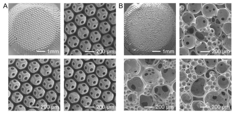
A) SEM images showing a lattice of uniform gelatin microspheres and three PLGA inverse opal scaffolds from different batches. B) SEM images showing a lattice of polydispersed gelatin microspheres and three non-uniform PLGA scaffolds from different batches.
The difference in the properties between an inverse opal scaffold with uniform structure and a counterpart possessing random pores typically results in a biased performance in engineering functional tissues. Our group conducted a systematic study to elucidate the importance of uniformity.[49] Using a diffusion device, we demonstrated that the diffusion of a model biomacromolecule, fluorescein isothiocyanate (FITC)-dextran (40 kDa), through the PLGA inverse opal scaffolds (pore size = 205 μm), had a similar rate with the control where no scaffold was present (Figure 11A). Such a rate was significantly reduced to half that of the control when non-uniform PLGA scaffolds (average pore size = 202 μm) were used. Meanwhile, the non-uniform scaffolds exhibited much larger standard deviations at all time points than the inverse opal scaffolds due to the batch-to-batch variations. The cells were then seeded into the two types of scaffolds to investigate their distribution. The results demonstrated that the cells were homogeneously scattered in the inverse opal scaffold, whereas their distribution in the non-uniform scaffold was completely random (Figure 11B). Clearly, the uniform pores and large windows in the inverse opal scaffolds facilitated the high seeding efficiency and efficient cell migration. Quantification of cell distributions in the scaffolds is shown in Figure 11C.
Figure 11.
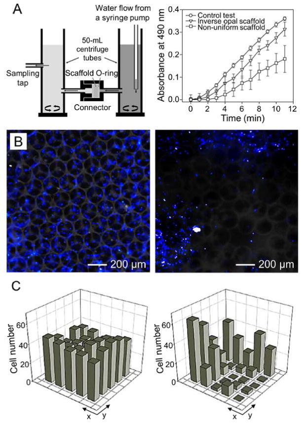
A) Schematic illustration showing a flow device for testing the diffusion of macromolecules through a porous scaffold and the plots showing the diffusion rates of FITC-dextran (40 kDa) through PLGA inverse opal scaffolds, non-uniform scaffolds, and a control without any scaffold. B) Fluorescence micrographs showing the distribution of the NIH/3T3 fibroblasts in a PLGA inverse opal scaffold and a non-uniform PLGA scaffold, after 7 days of culture. The nuclei of the cells were stained in blue. C) Quantitative analyses showing the distribution of the cells in the two types of scaffolds in (B), respectively. Reproduced with permission.[49] Copyright 2010, American Chemical Society.
In the same work, we further performed a differentiation analysis on the osteogenesis of the MC3T3 preosteoblasts in PLGA/HAp composite inverse opal scaffolds with two different pore sizes of 211 and 313 μm, respectively, as opposed to a non-uniform scaffold with an average pore size of 200 μm.[49] Both optical and electron microscopy analyses revealed that, a large amount of complexes containing both organic and inorganic ECM components were found inside the pores of the inverse opal scaffold with a pore size of 211 μm. By contrast, only a limited amount of mineral was deposited on the surface of the scaffold with a pore size of 313 μm. Interestingly, while a moderate amount of ECM was observed in the large pores (around 200 μm) of the non-uniform scaffold, most of the smaller and/or larger pores in the scaffolds were either free of visible ECM or occluded by the fibrous ECM. Recently, Hofmann and coworkers also demonstrated that inverse opal scaffolds exerted a more pronounced effect on the osteogenic differentiation of human mesenchymal stem cell (MSCs) relative to scaffolds prepared by salt-leaching.[84] Therefore, the behaviors of the cells in a scaffold are probably modulated by the parameters of the individual pore where they reside in rather than the properties of the bulk scaffold. For inverse opal scaffolds with uniform pores, such a microenvironment in each pore is tightly controlled to favor the coherent cell responses; for scaffolds with non-uniform pores, on the contrary, it is the collective properties that determine the outcome of the final bulk tissue as each pore offers a differential microenvironment for the cells to respond to. This notion further emphasizes the significance of scaffold uniformity in tissue engineering, making the inverse opal scaffolds invaluable for biomedical applications.
3. Biomedical Applications
Due to their unique features in terms of uniform and well-controlled pore sizes, long-range ordered structure, and homogeneous interconnectivity, inverse opal scaffolds have been explored for a wide spectrum of biomedical applications. Notable examples include but are not limited to, cell (co-)culture, production of multicellular spheroids, investigation of cell migration and neovascularization, tissue engineering, and wound healing. These applications are separately discussed in the following sections.
3.1. Cell (Co-)Culture
Compared with non-uniform scaffolds, inverse opal scaffolds possess many advantages for cell culture. First, the uniform and interconnected porous structure facilitates cell distribution and migration, as well as efficient transport of oxygen, nutrients, and metabolic wastes.[3,4,7] These features are critical for cells to homogenously distribute and expand inside the 3D framework. Second, due to the uniformity among different batches, tissue development from the seeded cells is highly reproducible.[5] Third, the pore sizes of each inverse opal scaffold can be conveniently tuned by varying the diameters of the templating microspheres and the fabrication conditions.[5,63] In addition, the highly ordered structure also makes it easier to computationally simulate the diffusion and other processes than those scaffolds with non-uniform pores.[85] Taken together, inverse opal scaffolds present a highly favorable microenvironment for cells to reside in and respond to.[5,24]
Kotov and co-workers first demonstrated such an application by culturing cells in an inverse opal scaffold fabricated from silica using a sol-gel procedure.[21] Cell viability assay suggests that both cell adhesion and proliferation were reasonably high over an extended period of time. They analyzed the correlation between the cell distribution and the pore size. Due to the optimal cell-cell and cell-matrix interactions, HepG2 human hepatocellular carcinoma cells exhibited higher cell density inside the scaffold with a pore size of 75 μm compared to those with smaller (10 μm) or larger pores (160 μm). Under similar culture conditions, HS-5 human bone marrow cells formed smaller clusters than HepG2 cells in scaffolds with similar pore sizes as a result of the larger cell dimension. To enhance the interactions between the cells and the inverse opal scaffold, fibrous structure was also incorporated into the surface of the cavities. For example, Giachelli and co-workers utilized an acetone-induced phase separation method to generate an inverse opal scaffold containing nanofibrous fibrin.[59] Enhancement was observed for both metabolic activity and spreading of NIH/3T3 fibroblasts over a culture period up to 6 days. Through the use of lyophilization, we developed a chitosan-based inverse opal scaffold with a nanofibrous texture.[23] The resultant scaffold supported the uniform distribution and sustained proliferation of MC3T3 preosteoblasts throughout the scaffold for up to 21 days.
Inverse opal scaffolds with a periodically ordered structure provide an ideal platform to study the cell-matrix interactions by offering a well-defined 3D microenvironment. Lin, Cristo, and co-workers analyzed the morphology and organization of the cells residing inside an inverse opal scaffold made of cross-linked gelatin. They concluded that different types of cells produced distinct organizational patterns.[65] MDKC kidney epithelial cells showed a cyst-like (closed hollow lumen) structure with a polarized orientation. C2C12 myoblasts fused into multinucleated myotubes, which connected the cell bodies in separate pores through the windows. Interestingly, NIH/3T3 fibroblasts adopted a series of different morphologies, including spreading along the walls, straddling over the pores with long pseudopodia, and squatting on the walls with short pseudopodia (Figure 12A,B). The morphology of cells inside the inverse opal scaffolds was also correlated with the pore size. Using PS inverse opal scaffolds as an example, we demonstrated that the spatial orientation of the cells was closely related to the size of the individual pore in which the cells resided (Figure 12C). When the pore size was fixed at 60 μm, human MSCs with a similar size assumed a completely 3D morphology stretching across the pores. When the pore size was enlarged to 90 μm, the cells took a partial 3D morphology. When the pores were further increased to 250 μm, much larger than the dimensions of the cells, the scaffold essentially presented a local environment similar to that of a two-dimensional (2D) substrate. In this case, the cells only spread on the skeleton of the scaffold as they would normally respond on 2D substrates.
Figure 12.

A,B) Confocal projection and 3D reconstructed images showing the different morphologies of fibroblasts grown in a gelatin inverse opal scaffold. The f-actin and nuclei of the cells were stained in green and blue, respectively. Reproduced with permission.[65] Copyright 2011, Royal Society of Chemistry. C) Confocal projection images showing human MSCs grown in PS inverse opal scaffolds with pore sizes of 60, 90, and 250 μm, respectively. The f-actin and nuclei of the cells were stained in red and blue, respectively.
While single-cell culture systems are effective for the study of cell-scaffold interactions, it remains insufficient where cell-cell interactions are required. To this end, two general strategies have been developed for simultaneous inclusion of two or more cell lineages inside a single inverse opal scaffold. One approach is to directly incubate different cells in the same cavities (Figure 13A), by seeding one type of the adherent cells on the surface of the pores followed by the introduction of another cell type (usually non-adherent). This concept was demonstrated by Kotov and co-workers using a PAAM hydrogel inverse opal scaffold whose surface had been modified with multiple layers of clay/PDDA to promote cell attachment.[74] As indicated in Figure 13B–D, after 5 days of co-culture, Hs202.Th anchorage-dependent human thymus epithelial cells densely covered the entire surface of the scaffold, whereas the non-adherent HL-60 human monocytes were entrapped inside the scaffold with a uniform distribution. Computational modeling revealed that the floating cells were effectively entrapped in the spherical cavities and spent a significant portion of time proximal to the matrix and cells adhering to the walls.
Figure 13.

A) Schematic illustration of co-culturing two types of cells in the same cavities of an inverse opal scaffold. B,C) Confocal images showing (B) the initial culture of the adherent thymic epithelial cells (green) in a PAAM inverse opal scaffold, and (C) subsequent seeding of the non-adherent monocytes (red) in the scaffold. D) Magnified image showing the interaction between the two types of cells. Reproduced with permission.[74] Copyright 2006, Royal Society of Chemistry. E) Schematic illustration showing the co-culture of two types of cells in an inverse opal scaffold by encapsulating one type in the backbone followed by subsequent seeding of another type in the pores. F) Schematic illustration of co-culturing GFP-expressing HUVECs and mCherry-expressing MSCs in a GelMA inverse opal scaffold. G–I) Confocal optical micrographs obtained from the indicated focal planes shown in (F). Reproduced with permission.[86] Copyright 2014, Wiley-VCH.
Another approach is to co-culture distinct cell populations in a spatially separated manner, which can be achieved by encapsulating one type of cells in the scaffold matrix during the infiltration process and subsequently seeding another type of cells on the surface of the pores after removal of the template (Figure 13E). Different from the previous co-culture strategy, this approach allows for the construction of heterogeneous cell-cell compartments to simulate complex cellular microenvironments, such as stem cell niches or tumor regime. Due to the presence of cells in the scaffold matrix, the template removal process should be biocompatible and benign. Mooney and co-workers utilized an all-hydrogel approach to fabricate an inverse opal scaffold by templating against Ca2+-cross-linked alginate microspheres.[86] They then embedded green fluorescent protein (GFP)-expressing human umbilical vein endothelial cells (HUVECs) inside the photo-cross-linkable gelatin methacryloyl (GelMA) and infiltrated it into the voids of the alginate lattice. After crosslinking GelMA with UV light, the alginate microspheres were quickly dissolved with a Ca2+-chelator, ethylenediaminetetraacetic acid (EDTA). MSCs expressing mCherry red fluorescent proteins (RFPs) were then seeded into the cavities and allowed for adhesion (Figure 13F). Confocal images obtained from different focal planes after 3 days of culture suggest the formation of a concentric circular pattern, with GFP-expressing cells in the periphery and mCherry-expressing cells in the interior (Figure 13G–I). Kim and co-workers further optimized the fabrication parameters of the GelMA inverse opal scaffolds.[87] They concluded that low-viscosity alginate, low calcium cross-linking concentration, as well as low concentrations of alginate and GelMA contributed to the high viability of the cells encapsulated in the GelMA matrix after removal of alginate microspheres by EDTA.
3.2. Production of Multicellular Spheroids
Cells typically exhibit reduced cell-cell and cell-matrix interactions in 2D cultures compared to their intrinsic 3D organizations in vivo.[88,89] As a result, extensive information will be lost when investigating the behaviors of cells cultured on 2D substrates, particularly for cellular functions that are highly dependent on 3D configurations such as protein and cytokine secretions.[89,90] To bridge the gap between in vitro 2D cultures and in vivo 3D tissues, multicellular spheroids, or cell bodies, have been actively explored to recapitulate the highly dense tissues and intercellular interactions.[91] Inverse opal scaffolds hold great potential for the production of a large number of uniform, multicellular spheroids at one time. Theoretically, the maximal diameter of the cell bodies would be less than about 77% of the pore size, or 50% of the pore volume due to the spatial confinement.[92] As such, the size of the spheroids can be conveniently adjusted by simply altering the pore size of the scaffold or varying the culture period.
In an early study, Kotov and co-workers used a cell-repulsive PAAM inverse opal scaffold to fabricate liver spheroids from HepG2 cells.[92] The cells started to aggregate together inside the pores from day 1 but still with distinguishable individual cells (Figure 14A). In the subsequent phase, the individual cells gradually merged with each other through intense cell-cell interactions. Finally, mature liver spheroids were formed at day 5, which were coated with a thin layer of ECM to appear as smooth cell bodies (Figure 14B). Reconstructed 3D confocal image indicates that the mature liver spheroids were entrapped in the individual pores of the scaffold (Figure 14C). In another study, Kotov and co-workers examined the toxicity of CdTe quantum dots (QDs) and Au nanoparticles (AuNPs) toward the 3D liver spheroids produced in similar PAAM inverse opal scaffolds.[93] Morphological analysis indicates that in contrast to 2D cell cultures, the toxicity of CdTe QDs toward the spheroids was markedly reduced (Figure 14D,E). SEM characterization further revealed that the outer structure was significantly destructed, whereas the cells in the inner cluster remained intact (Figure 14F). AuNPs stabilized with cetyltrimethylammonium bromide (CTAB) showed similar impact on the spheroids as CdTe QDs. The reduced toxicity was presumably attributed to the hindered mass transport as a result of the densely packed cells and well-developed ECM.[93,94]
Figure 14.

A,B) Confocal optical micrographs showing the formation of HepG2 spheroids in a PAAM inverse opal scaffold at day 1 and day 5 post seeding, respectively. C) 3D reconstructed confocal image of a mature liver spheroid entrapped in a single pore. Reproduced with permission.[92] Copyright 2009, Elsevier. D,E) Confocal images of live/dead-stained spheroids (D) before and (E) after exposure to CdTe QDs. F) SEM image of a spheroid after exposure to CdTe QDs. Reproduced with permission.[93] Copyright 2009, Wiley-VCH.
Since the PAAM scaffolds are difficult to disassemble under mild conditions, the produced multicellular spheroids cannot be released from the scaffolds for subsequent usage and analyses. In this regard, a new class of inverse opal scaffolds made of disintegrable alginate was developed by our group for the production of uniform embryoid bodies (EBs).[51] The fabrication procedure consisted of four steps: seeding of embryonic stem cells (ESCs) into the alginate inverse opal scaffolds, cell proliferation and EB formation, disintegration of the scaffolds with a Ca2+-chelating agent such as EDTA, and harvest of the released EBs (Figure 15A). The alginate inverse opal scaffolds possessed a uniform structure with interconnected pores (Figure 15B). Facilitated by the non-adherent property of alginate, ESCs gradually aggregated into EBs with uniform sizes inside the pores (Figure 15C). Upon treatment with EDTA, the alginate scaffold was disintegrated, leading to the fast release of EBs within a few minutes (Figure 15D). The collected EBs maintained high viability and capability to differentiate into multiple lineages. Significantly, 500–1000 EBs could be produced from a single inverse opal scaffold with four layers of pores over an area of 30 mm[2] (Figure 15E). Such a scalable technique for the production of cell bodies holds promise for tissue engineering and regenerative medicine where the utilization of a large number of multicellular spheroids is required.
Figure 15.

A) Schematic illustration of the major steps involved in the fabrication of EBs with an alginate inverse opal scaffold: i) seeding of ESCs into the pores of a scaffold; ii) proliferation of the cells under the confinement of the pores; iii) disintegration of the scaffold with a PBS solution containing 100 mM EDTA and 100 mM K2HPO4; and iv) separation of EBs from the debris of the disintegrated scaffold. B) Bright-field optical micrograph showing an alginate inverse opal scaffold with a uniform pore size of 250 μm. The inset shows the SEM image of a single pore of a freeze-dried sample. Scale bar: 100 μm. C) Superimposed micrograph showing EBs grown in a scaffold after 14 days of culture. D) Bright-field optical micrograph showing EBs recovered from a disintegrated scaffold. Reproduced with permission.[51] Copyright 2012, Wiley-VCH. E) Fluorescence optical micrograph at a lower magnification showing ca. 150 uniform EBs formed in the first layer of a scaffold. Reproduced with permission.[5] Copyright 2013, Royal Society of Chemistry.
3.3. Cell Migration Studies
Inverse opal scaffolds possess a well-defined porous structure with outstanding uniformity and interconnectivity, which provides adequate space and pathways for not only mass transport but also cell migration.[5,24] Functional biomolecules can be grafted onto the pore surface via covalent cross-linking, non-covalent modification, or physical adsorption to mediate cell adhesion and motility (e.g., chemotaxis). Using PEG-based inverse opal scaffolds, Irvine and co-workers studied the migration of T lymphocytes between adjacent pores.[22] Given that T cell activation requires the rapid and efficient identification of antigens presented by dendritic cells, they conducted an explicit set of investigation to seek for the optimal motility-inducing cues that promote T cell migration. It was found that the intercellular adhesion molecule-1 (ICAM-1) and fibronectin-decorated PEG surfaces did not facilitate strong cell adhesion and subsequent migration. They then infused the scaffolds with a fibrillar collagen gel to support the migration of T cells by providing a physical network. Compared to the protein-coated scaffolds, the composite scaffolds exhibited an enhanced impact on T cell migration. They further anchored adhesion- and migration-promoting chemokine CCL21 on the pore surface to enable chemotaxis within the scaffold. The hybrid scaffold was found to support the motility of the less motile naive T cells, thereby providing a platform to study the chemotactic response of immune cell homing to the secondary lymphoid organs.
Aside from biochemical modification that can be used to construct a suitable milieu for cell migration, Griffith and co-workers systematically probed the effects of the porosity, adhesiveness, and elasticity of PEG-based inverse opal scaffolds on the motility of MSCs.[54] Their results indicated that the pore size had the most significant impact on cell migration, which was further influenced by the matrix adhesiveness and stiffness. Specifically, when the void space was much smaller than the cells, their migration was largely restricted by the dimension of the pores; however, for the scaffolds with pore sizes larger than cell dimensions, the cells actually encountered a quasi-2D microenvironment, making the adhesiveness and stiffness the main factors to affect cell motility. Accordingly, maximal cell displacement was observed in the scaffold with intermediate pore and window sizes (40 and 12 μm, respectively) along with a stiff (100 kPa) and most adhesive (12.5-mM RGD) matrix. In a complementary study, we demonstrated that cell migration was strongly dependent on the pore and window sizes.[63] As shown in Figure 16, inverse opal scaffolds with larger pore and window sizes induced faster migration of HUVECs into the interior of the scaffolds, with the distance proportional to the pore/window sizes (Figure 16B–D). When the scaffolds had the same pore sizes, the window size then became the decisive factor, with those possessing larger windows inducing more pronounced cell migration (Figure 16C,E). Interestingly, for the scaffolds with a smaller pore size but larger window size, the migration of cells was still faster than those with a larger pore size but smaller window size (Figure 16D,E). In another study, Sivaniah, Guck, and co-workers reported that the decrease in substrate stiffness led to an increased migration distance,[53] somewhat contrary to the conclusions drawn by Griffith and co-workers, probably due to the different cell type (NB4 cells, a leukemic myeloid precursor cell line) and scaffold material (PAAM coated with poly-D-lysine) used in their study. They inferred that the constraint force exerted by the scaffolds improved the capability of the cells to actively deform their surroundings for narrow space entrance. Two cytoskeleton inhibitors (against microtubule and actin, respectively) were also included to explore their effects on cell migration within the scaffolds, demonstrating the potential of using such a system for drug screening.
Figure 16.

A) Quantification of HUVECs migration over 10 days in four types of inverse opal scaffolds with different pore and window sizes. “*” indicates the statistical significance between the two groups (p < 0.05). B–E) Fluorescence micrographs showing the invasion of HUVECs into the four types of scaffolds at day 10. The f-actin and nuclei are shown in green and red, respectively. Reproduced with permission.[63] Copyright 2013, Wiley-VCH.
Inverse opal scaffolds were also integrated with microfluidic devices to study cell migration under an electric field (i.e. electrotaxis or galvanotaxis). Cheng and co-workers incorporated a gelatin inverse opal scaffold in the microfluidic device to mimic the structure of pulmonary alveoli.[95] The responses of three lung cancer cells toward an electric field were investigated, where CL1-0 showed no obvious electrotactic response, CL1-5 moved toward the anode, and A549 migrated toward the cathode. Moreover, compared to 2D cultures, cells in the scaffolds exhibited weaker electrotactic response because of the obstructed migration pathway. In another study, Yu and co-workers demonstrated that the keratocytes in 3D gelatin inverse opal scaffolds responded to an applied electric field with a zig-zag migration pattern along the edge of the pores and between adjacent cavities.[96] In 2D microchannels, however, the keratocytes exhibited an almost straight-line trajectory. These studies provide valuable information in understanding the effect of electrophysiological cues on in vivo cell migration.
3.4. Neovascularization
It is almost impossible to accurately evaluate how pore sizes influence tissue infiltration with conventional non-uniform scaffolds that possess a broad distribution of pore sizes and poorly defined geometry, particularly for such a complex process as neovascularization. In this aspect, the well-defined and controllable inverse opal scaffolds provide a potent platform to elucidate the effect of these physical parameters on in vivo tissue formation and vascularization.
Ratner and co-workers demonstrated that the relatively small pore sizes in the range of 35 to 160 μm favored in vivo vascular in-growth into PHEMA inverse opal scaffolds along with minimum fibrous tissue formation.[20] Using β-tricalcium phosphate (β-TCP) inverse opal scaffolds with different pore sizes (300–700 μm) but fixed window size (120 μm), Bai and coworkers revealed that larger pore sizes were more favorable for the growth of blood vessels than small pores.[57] They suggested that, when the pore size was smaller than 400 μm, the growth process was restricted as a result of the limited void space, leading to the formation of narrow blood vessels. Besides, the amount and occupancy of fibrous tissues were much greater in these scaffolds, which further contributed to the reduction of the available space. We also conducted a systematic study with regard to the effect of pore size on neovascularization in vivo using biodegradable PLGA scaffolds with a series of pore sizes.[61,97] Histological analyses showed that the nascent vessels were observed to penetrate into all the scaffolds at 2 and 4 weeks post subcutaneous implantation in mice (Figure 17A,B). In contrast to the scaffolds with small pore sizes (79 and 147 μm), those with large pore sizes (224 and 312 μm) facilitated the growth of vessels with higher density at 2 weeks post implantation. Moreover, the initially formed vessels had the similar diameter of approximately 15 μm regardless of the pore size. After 4 weeks, the average vessel diameters increased to 25 and 45 μm for scaffolds with small and large pore sizes, respectively. As the vessels broadened in diameter from 2 to 4 weeks, the densities of the vasculature in scaffolds with small pore sizes greatly increased, whereas there was a decreasing trend for the scaffolds with large pore sizes. Quantitative data from the histological images evidenced such an observation (Figure 17C,D). All these results indicated that scaffolds with small pore sizes supported the formation of small vessels at higher densities close to the surface region, whereas scaffolds with large pore sizes favored the development of large vessels with low densities but deep penetration depths.
Figure 17.

A,B) Bright-field micrographs of the representative hematoxylin and eosin-stained sections showing the patterns of neovascularization in the PLGA inverse opal scaffolds with uniform pore sizes of 79, 147, 224, and 312 μm, respectively, after (A) 2 and (B) 4 weeks of subcutaneous implantation in nude mice. Blood vessels are indicated by yellow arrowheads and ‘S’ indicates scaffolds. C,D) Plots of (C) blood vessel density and (D) blood vessel-to-tissue area ratio as a function of the pore size at 2 and 4 weeks post implantation. “*” indicates the significant difference between two groups (p < 0.005), whereas “NS” means not statistically significant (p > 0.005). “**” indicates the significant difference relative to the value of the samples at 2 weeks. E,F) Schematic illustrations of the proposed mechanisms by which the pore size of a scaffold affects neovascularization in vivo. Reproduced with permission.[61] Copyright 2013, Wiley-VCH.
The schematics in Figure 17E,F, illustrate how the pore size affects neovascularization in vivo.[61] For scaffolds with small pore sizes, the infiltrated tissues and nascent vessels encounter a limitation to penetrate deeply into the scaffold after they reach the bottom of the pores at the surface as a result of the small windows. As the vessels invade deeper, they are easily separated from each other in different pores. Therefore, the vessels show a tendency of growing by themselves instead of being merged or interconnected. On the contrary, for the scaffolds with large pore sizes, the windows are large enough to enable the invasion of multiple vessels into the same pores underlying the surface, which greatly increases the chances for the vessels to merge and form large/interconnected networks. It is worth mentioning that, the discrepancies in the optimal pore size for maximal neovascularization and minimal fibrosis might have originated from the difference in either the materials (e.g., hydrophobic polymer, hydrogel, or ceramics) or animal models (e.g., mouse, rat, or rabbit).[5] However, we believe that if these conditions are unified, the results across multiple experiments should be persistent and highly reproducible.
Proangiogenic growth factors such as vascular endothelial growth factor (VEGF) and platelet-derived growth factor (PDGF) can also be incorporated into the inverse opal scaffolds to stimulate the formation and maturation of blood vessels. Davies and co-workers constructed a miniature osmotic pump that was superficially coated with a layer of inverse opal structure made of polyurethane to evaluate the dosage dependence of VEGF on neovascularization.[98] Consistent delivery of VEGF at concentrations of 15, 150, and 1500 ng per day from the scaffolds for up to 6 weeks was studied. For the group delivered with 15 ng of VEGF per day, they did not observe the pronounced effect on vascular formation. When the dosage was increased to 1500 ng per day, the vessel formation was suppressed after 20 days in spite of its most striking effect at the initial stage. Only the group with moderate delivery of 150 of VEGF per day showed the continuously increased vascularization. This study indicated that a proper concentration of VEGF was of great importance to favor the optimal growth of blood vessels. In another study, the same research group employed micro-computed tomography (micro-CT) to assess the impact of VEGF on vascularization.[99] Compared to the control group where phosphate-buffered saline (PBS) was delivered, the one with continuous delivery of VEGF showed a 1.47-fold increase in average vessel diameter and a 17.31-fold increase in total vessel volume. Besides VEGF, surface modification of heparin can also impose a positive impact on vascularization.[100] Davies and co-workers combined VEGF and PDGF into heparinized inverse opal scaffolds to promote the sustained neovascularization and vessel maturation.[101] Relative to the elution profile of PDGF from the heparinized scaffolds, a faster release kinetics was observed for VEGF as shown in Figure 18A,B (VEGF: 75 ng per h after 24 h; PDGF: 86 pg per h over 7 days). Histological analysis demonstrates that at 2 months post implantation in rats, the heparinized surface resulted in an increased vessel ingrowth, while a further enhanced vascularization was found in the scaffolds with the combined release of VEGF and PDGF (Figure 18C,D). Compared to the heparinized scaffolds, the vessel density was increased by 69 ± 17% for the PDGF-releasing scaffolds and 71 ±2 3% for the VEGF/PDGF-releasing scaffolds, respectively (Figure 18E). The arterialization at 2 months post implantation was further analyzed by immunostaining of α-smooth muscle cell actin (α-SMA) in the explants. In contrast to the heparin-coated scaffolds, those loaded with VEGF and PDGF resulted in a significant increase (66 ± 22%) in the number of arterioles (Figure 18F–H). These studies indicated that the heparin-modified scaffolds allowed for the simultaneous loading of multiple angiogenic growth factors to favor the persistent release and thus enhance the vascularization.
Figure 18.

A,B) Elution profiles of VEGF and PDGF-BB from the heparin-modified PU inverse opal scaffolds at 37 °C over 8 days: (A) elution of VEGF from the scaffolds loaded with VEGF alone and with VEGF and PDGF-BB; (B) elution of PDGF-BB from the scaffolds loaded with PDGF-BB alone and with VEGF and PDGF-BB. C,D) Representative micrographs of CD31-immunostained (C) heparin-coated scaffold and (D) scaffold loaded with VEGF and PDGF-BB, at 2 months post subcutaneous implantation. E) Quantification of the capillary densities. F,G) Representative micrographs showing α-SMA immunostained (F) heparin-coated scaffold and (G) scaffold loaded with VEGF and PDGF-BB, at 2 months post subcutaneous implantation. E) Quantification of arteriole densities. Reproduced with permission.[101] Copyright 2012, Mary Ann Liebert.
3.5. Cardiac Tissue Engineering
Certain tissues such as the myocardium are typically characterized by their thick matrix and high consumption of oxygen.[102] In this respect, it is necessary to use an appropriate scaffolding system that is capable of inducing fast vascularization to maintain cell viability upon in vivo implantation and thereby facilitate tissue regeneration.[103] Due to their strong ability to modulate the neovascularization process, inverse opal scaffolds have recently been exploited for cardiac tissue engineering. Ratner and co-workers first reported such an application using poly(2-hydroxyethyl methacrylate-co-methacrylic acid) (PHEMA-co-MAA) inverse opal scaffolds.[104] The specially designed scaffolds included a set of parallel channels with a diameter and spacing of both 60 μm to guide the development of anisotropic myocardium bundles. The parallel channels were surrounded by an inverse opal structure with a 30-μm pore size and a 15-μm window size for neovascularization (Figure 19A,B). The resultant construct allowed for high-density seeding of primary chicken embryonic-derived cardiomyocytes, but with a slight gradient from the outside inward as shown in Figure 19C. Histological and immunostaining results revealed that the channels were predominantly occupied by cardiomyocytes, whereas noncardiomyocytes were distributed throughout the porous structure (Figure 19D). Different from the non-cardiomyocyte-dominated constructs populated by chicken embryonic-derived cardiomyocytes, the cardiomyocytes were selectively enriched in the scaffolds with human ESC derived cardiomyocytes (hESC-CMs). In the parallel channels, the cardiomyocytes were also observed to express contractile proteins such as troponin T (Figure 19E), and the seeded cells remained viable due to the presence of large pores for mass transport (Figure 19F). Furthermore, the impacts of pore size on fibrous tissue formation and neovascularization were analyzed by patching the collagen-coated PHEMA-co-MAA scaffolds into the myocardium of nude rats for 4 weeks. Quantitative data demonstrate that the scaffold with a pore size of 30 μm induced the maximal neovascularization while minimal fibrosis (Figure 19G,H). They then performed immunostaining to identify the phenotypes of the infiltrated macrophages, where the nitric oxide synthase 2 (NOS2) corresponds to the M1 activation state and the MΦ mannose receptor (MMR) indicates the M2 activation state.[105] Based on the increased MMR, they argued that the polarity the macrophages was shifted toward the pro-healing M2 phenotype, which possibly interprets the strikingly good vascularization (Figure 19I). This work also demonstrated an interesting concept for fabricating multi-compartment scaffolds to engineer complex tissues, where the aligned microchannels were used to induce the formation of cardiac muscle bundles and the inverse opal structure could maximize the neovascularization as well as minimize the unfavorable fibrotic/inflammatory response.
Figure 19.

A,B) SEM images of a bimodal scaffold. The scaffold was consisted of 60-μm channels spaced at 60-μm apart. Channel walls contained spherical pores with a 30-μm diameter and 15-μm interconnects. Scale bars: 100 and 20 μm, respectively. C) Digital volumetric image showing a scaffold (green) seeded with primary chick cardiomyocytes (red). Scale bar: 300 μm. D) Chick cardiomyocyte-seeded structure with positive staining of sarcomeric myosin heavy chain (brown). Scale bar: 50 μm. E) Immunostaining against troponin T in hESC-CM seeded in the channel constructs. Scale bar: 50 μm. Inset: 100 × magnified image of the boxed area. Scale bar: 20 μm. F) Confocal image obtained after live/dead assay showing the distribution of cells in the scaffold (autofluorescence in red). Scale bar: 400 μm. G–I) Quantification results of neovascularization, fibrosis capsule formation, and number of NOS2+/MMR+ macrophages, respectively, in the subcutaneously implanted myocardial constructs with different pore sizes. Reproduced with permission.[104] Copyright 2010, National Academy of Sciences USA.
More recently, Freed and co-workers reported an scalable scaffold unit for constructing the vascularized cardiac tissues.[106] The designed device consisted of three functional segments with a stacked configuration: a microfluidic base, a vascular-parenchymal inverse opal interface, and a cardiac scaffold. Both the microfluidic base and the cardiac scaffold were made of slowly degradable polymers to offer sufficient mechanical support for vascularization in vivo. The porous inverse opal interface, however, was made of rapidly degradable polymers to provide efficient mass transfer in vitro and then fast erosion to integrate the seeded cardiomyocytes with nascent blood vessels derived from the host after implantation in vivo. Neonatal rat cardiomyocytes loaded into the scaffolds attached and distributed evenly throughout the pores, which were supplied by the flow of culture medium from the microfluidic base. Cell culture experiments indicate that the inverse opal scaffolds could support cell attachment, elongation, and penetration, making this system applicable to high-density culture of cardiomyocytes in promoting the development of vascularized myocardium.
3.6. Bone, Cartilage, and Osteochondral Tissue Engineering
Bone tissue engineering relies on either implantation of pristine porous scaffolds to favor the naturally occurring bone formation or introduction of scaffolds loaded with osteogenic cells to promote bone repair in vivo.[68,69] Both situations require a robust physical support and a suitable microenvironment for the cells to respond to. To enhance osteogenesis, several inorganic materials can be employed to decorate the surface of a scaffold, with the apatite family (e.g., HAp) being one of the most widely used components.[40,107] HAp, the major mineral phase in natural bones, is reported to possess superior biocompatibility, osteoconductivity, and osteoinductivity, making it a good candidate as an additive for bone tissue engineering.[67-69] In general, two strategies have been adopted for apatite incorporation, including direct loading of apatite nanoparticles into the scaffolding materials and generation of apatite coating via a mineralization process.[41,45] In addition, delivery of bone-stimulating growth factors such as recombinant human bone morphogenetic protein-7 (rhBMP-7) was also proven to be effective in enhancing bone regeneration.[108]
Giachelli and co-workers fabricated nanofibrous fibrin-based inverse opal scaffolds and further functionalized them via both calcium phosphate deposition and direct incorporation of HAp nanoparticles.[58] In contrast to the scaffolds with fibrin alone and HAp nanoparticles, the osteoblast-like cells exhibited higher alkaline phosphatase (ALP) activity and bone marker gene expressions in the scaffold with additional deposition of calcium phosphate. In a mouse calvarial defect model, all these scaffolds were demonstrated to stimulate bone formation, which was further enhanced by the addition of rhBMP-2. Since ALP can transform pyrophosphate to phosphate and induce the formation of HAp,[109] functionalization of an inverse opal scaffold with ALP also potentially facilitates the differentiation and mineralization of osteoblasts. Somerman and co-workers proved this concept by covalently immobilizing ALP onto nanofibrous fibrin inverse opal scaffolds.[110] Relative to the scaffolds with fibrin alone, they observed better mineral deposition and higher expression of osteoblast marker genes. The enhanced bone formation was demonstrated in a model of mouse calvarial defects as well.
PLGA is another commonly used scaffolding material for bone regeneration due to its biocompatibility, strong mechanical strength, and tunable degradability.[55] Our group compared three different formulations of PLGA-based inverse opal scaffolds to evaluate their capability in promoting the maturation of preosteoblasts in vitro.[48] Besides the pure PLGA scaffolds, HAp was impregnated into the backbone of the scaffolds during the infiltration process to obtain the PLGA/HAp scaffolds. In the third formulation, an additional layer of apatite was coated on the surface of the PLGA/HAp scaffolds via an induced mineralization procedure.[70] Micro-CT and SEM analyses indicate that the apatite-coated PLGA/HAp scaffolds induced the largest amount of mineral deposition and a homogeneous mineral distribution throughout the scaffold, whereas the pristine PLGA scaffolds showed minimal osteoinductivity with fairly limited mineralization.
Cartilage regeneration poses another challenge in tissue engineering because the avascular characteristic of the articular cartilage has rendered the chondral defect suffer from poor regenerative capacity.[111] Therefore, the uniform distribution of chondrocytes may play a critical role in cartilage tissue engineering. Utilizing a biocompatible and biodegradable chitin/chitosan inverse opal scaffold, Kuo and coworkers analyzed the distribution and metabolism of the bovine knee chondrocytes (BKCs).[52] Their results showed that the BKCs exhibited a uniform distribution as well as a strong chondrogenic activity inside the scaffold. In a follow-up study, they further modified the chitin/chitosan inverse opal scaffold with heparin to promote the proliferation and differentiation of chondrocytes.[112] Over a 4-week culture period, both the viability of BKCs and the secretion of glycosaminoglycans (GAGs) and type II collagen were elevated as the weight percentage of heparin increased. In terms of the distribution of the cartilaginous components, no evident difference was observed between the periphery and the center, indicating that the heparinized inverse opal scaffold favored the uniform production of neocartilage.
The inverse opal scaffolds have also been applied to the regeneration of the osteochondral interface, one of the toughest tissues to be engineered due to the distinct properties between the cartilage and the underlying bony tissue as well as the presence of a transitional zone at the interface.[113] Ratner and coworkers developed a bi-layered inverse opal scaffold to provide a biomimetic transition for osteochondral regeneration.[114] The two layers, made of degradable PHEMA hydrogels, were intentionally designed with tailored pore sizes and bioactive molecules to promote the optimal regeneration of cartilage and subchondral bone, respectively. The prochondrogenic layer had 200-μm pores with a hyaluronic acid (HAc) coating (PHEMA(200)/HAc), while the opposing layer contained pores of 38 μm coated with HAp (PHEMA(38)/HAp) (Figure 20A–C). The magnified image in Figure 20B suggests that there was a thin layer of non-porous PHEMA between the bilayers, which was desirable for the independent chondrogenesis and osteogenesis in the two phases. After separately seeding MSCs and chondrocytes into the PHEMA(38)/HAp bone section and PHEMA(200)/HAc cartilage portion for 2 weeks, respectively, independent growth of the two different cells was observed in the individual layers (Figure 20D). The in vitro analysis after 4 weeks of culture was performed to demonstrate the potential of the bi-layered scaffold in supporting the individual chondrogenesis and osteogenesis. Inside the cartilage layer, the chondrocytes remained viable with a spherical morphology and were embedded in the dense ECM throughout the cartilage side (Figure 20E). Histological staining of GAGs and type II collagen demonstrates the efficient chondrogenesis (Figure 20F,G). In the bone layers, MSCs formed an interconnected network within the pores with high cell density (Figure 20H). Alizarin red staining revealed the calcium deposition as a result of the osteoinductive nature of HAp (Figure 20I,J). Besides, an increased ALP activity was also observed. These results suggested that the structure of PHEMA(38)/HAp facilitated the osteogenic differentiation of human MSCs, whereas PHEMA(200)/HAc created a favorable microenvironment for chondrocytes to maintain their phenotype. Such a new platform utilizing the differential responses of cells to the localized physical/biochemical cues in an integrated bi-layer scaffold holds potential for the regeneration of an interface between two distinct tissues.
Figure 20.

A) SEM image showing the cross-section of a bi-layered inverse opal scaffold based on PHEMA(200)/HAc (upper layer) and PHEMA(38)/HAp (lower layer). B) Magnified image showing the interface area between the designated cartilage and the bone layer. C) Magnified image showing the designated bone layer, PHEMA(38)/HAp. D) A representative image of hematoxylin and eosin-stained section of the bi-layered scaffold seeded with human MSCs in the bone layer and chondrocytes in the cartilage layer, after 2 weeks of culture. E) SEM image of chondrocytes within the PHEMA(200)/HAc layer after 4 weeks of culture. F) Bright-field image showing alcian blue-stained section (proteoglycan in blue-turquoise and nuclei/cytoplasm in violet). G) Bright-field image showing the section stained for type II collagen. H) SEM image of human MSCs within the PHEMA(200)/HAc layer after 4 weeks of culture. I,J) Bright-field images showing the alizarin red-stained sections after 2 and 4 weeks of culture, respectively. Reproduced with permission.[114] Copyright 2013, Wiley-VCH.
3.7. Neural Tissue Engineering
It was reported that porous biomaterials can provide an appropriate microenvironment to promote axonal growth and neuronal survival.[115] Because of the superior interconnectivity and tightly controlled pore sizes, inverse opal scaffolds have emerged as a good candidate to culture neuronal tissues. Kuo and co-workers conducted a series of studies regarding neural tissue regeneration based on inverse opal scaffolds.[116] They first clarified the impact of pore uniformity on the preservation and differentiation of MSCs. Non-uniform and inverse opal scaffolds made of chitosan-gelatin were fabricated, the surfaces of which were further grafted with laminin-derived peptides (LDPs) to enhance cell adhesion. As expected, the cells distributed more homogeneously in the inverse opal scaffold than in the non-uniform scaffold. For the phenotypic preservation of MSCs, the inverse opal scaffold was more efficient to maintain the differentiation potency than the non-uniform scaffold. LDP alone could stimulate the neuronal differentiation, whereas the supplemented nerve growth factor (NGF) guided the majority of MSCs to differentiate toward mature neurons. In a subsequent study, they fabricated a chitinchitosan-gelatin inverse opal scaffold to direct the differentiation of induced pluripotent stem cells (iPSCs).[117] Compared with the non-uniform scaffold, the inverse opal scaffold stimulated the production of β3-tubulin (a marker of neuronal differentiation) and a smaller amount of stage-specific embryonic surface antigen-1 (SSEA-1, a marker of the undifferentiated state). In addition to the pristine scaffold, they also grafted functional peptides on the pore surface to promote the neuronal differentiation of iPSCs.[60,118]
3.8. Wound Healing
Percutaneous medical devices always encounter a significant risk of microbial infections via the cutaneous/biomaterial interface. Although antibiotics can be incorporated into devices to circumvent this threatening problem, no significant progress has been made as a result of the increased antibiotic resistance of microorganisms.[119] An effective approach is to heal the wound by directly integrating the medical device with the impaired skin to preclude bacteria invasion. Nevertheless, the stable epidermal attachment to the percutaneous biomaterial remains an issue. In this aspect, well-defined porous scaffolds can provide a suitable microenvironment for the cells surrounding the wound to attach and remodel so that a natural barrier could be formed, preventing bacterial colonization and biofilm propagation.[120]
Fukano and co-workers evaluated the cutaneous response to a PHEMA inverse opal scaffold in an ex vivo organ culture system based on the newborn foreskin biopsies.[121] Linking agent 1,1-carbonyldiimidazole (CDI) was used to functionalize the scaffold to enhance cell adhesion. The decorated surface was shown to improve the attachment of keratinocytes, fibroblasts, and endothelial cells. In contrast to the pristine material, the CDI-modified PHEMA scaffold facilitated the development of a PHEMA/skin interface with a pattern similar to the junctional epithelium. In another study, Olerud and co-workers evaluated the biological effect of the PHEMA rod-like inverse opal scaffold in a mice model.[122] Histological analyses demonstrate the epidermal and dermal integration with the PHEMA scaffold with minimal foreign body responses.
3.9. Extended Applications
In addition to the aforementioned applications, inverse opal scaffolds have also been explored for other extended usages in biomedicine. The first example involves the construction of bone marrow analogues. Kotov and co-workers fabricated silicate and PAAM inverse opal scaffolds and coated them with multiple layers of clay and PDDA using an LBL approach to enhance cell adhesion.[73] MSCs were seeded into the scaffolds to form a support cell layer on the pore surface to mimic the bone marrow stroma. CD34+ hematopoietic stem cells (HSCs) were then inoculated to function as the undifferentiated cells to investigate their differentiation potential into other lineages. The established bone marrow constructs were shown to support the differentiation of CD34+ HSCs into B-lymphocyte. The interaction between HSCs and the stromal human MSCs in the 3D space was of great importance to promote the production of functional B cells and antigen-specific antibodies. Intriguingly, mature human immune cells were successfully derived by implanting the bone marrow constructs loaded with CD34+ HSCs on the backs of severe combined immunodeficiency (SCID) mice. To optimize the in vitro bone marrow differentiation niche, Kotov and co-workers conducted another evaluation with a set of different scaffolds.[123] They concluded that the inverse opal scaffolds could promote HSC-stromal cell interactions through both direct cell-cell contact and soluble cytokines, providing a microenvironment similar to the in vivo bone marrow. Compared to the 3D scaffolds inhibiting direct cell-cell communications, the inverse opal scaffolds were capable of maintaining HSCs in their quiescent state, indicating that the complex bone marrow niche could be simulated in vitro to a great extent.
As an extension of inverse opal scaffolds with multiple layers, monolayer scaffolds with uniform pores have been developed by our group for the fabrication of cell patches, which hold great potential for healing superficial injuries or tissue interfaces.[124] Similar to the fabrication process of an inverse opal scaffold, the PLGA scaffold with a hexagonal array of interconnected pores (SHAIP) was produced by templating against gelatin microspheres assembled in a single layer lattice (Figure 21A–D). As a model construct, the homogeneous skeletal muscle patches were created by seeding myoblasts into the SHAIPs. As shown in Figure 21E, the cells uniformly distributed throughout the patch. The SHAIPs were easy to handle, making them suitable for regular surgical procedures. The myoblasts in the SHAIPs could be further induced to differentiate into elongated, multinucleated myotubes interconnecting cell bodies in the adjacent pores. In vivo study was performed by subcutaneous implantation of the cellularized scaffolds in nude mice. Histological staining results revealed that the myoblast patches promoted the formation of homogenous muscle bundles and extensive vascularization surrounding the myotubes (Figure 21F), indicating the capability of the SHAIPs to generate functional interfacial tissue constructs for tissue engineering applications.
Figure 21.

A,B) Transmission bright-field optical micrographs showing the top view of (A) a monolayer lattice of gelatin microspheres and (B) a PLGA SHAIP. C,D) Reflection bright-field optical micrographs showing (C) a free-standing monolayer lattice of the gelatin microspheres after thermal fusion and (D) a free-standing PLGA SHAIP held by tweezers. E) Fluorescence micrograph showing a free-standing myoblast patch in a PLGA SHAIP; the cells were stained with calcein. F) Bright-field optical micrograph showing the hematoxylin and eosin-stained transverse section of the implant at 4 weeks post implantation. Yellow arrowheads indicate the blood vessels. Reproduced with permission.[124] Copyright 2014, Elsevier.
4. Conclusions and Perspective
We have discussed a new class of advanced materials commonly referred to as inverse opal scaffolds. They are best known for their identical, spherical pores interconnected by uniform, circular windows. The sizes of their pores and windows can be precisely controlled by engineering the template, a ccp lattice of monodispersed microspheres. After a discussion on the fabrication methods, including those used for the additional modification or functionalization of the pore, surface, and backbone, we highlighted the importance of uniformity in improving the reproducibility of experiments, as well as in promoting the diffusion of biomacromolecules, distribution of cells, and differentiation of progenitor/stem cells. We then presented an overview on the extensive use of such scaffolds in tissue engineering and regenerative medicine, including but not limited to cell (co-)culture, fabrication of multicellular spheroids, fundamental studies of cell migration and neovascularization, wound healing, as well as engineering/regeneration of cardiac, bone/cartilage/osteochondral, and neuronal tissues.
As a class of platform materials, inverse opal scaffolds are advantageous in offering a well-defined and controllable microenvironment for cells to respond to and for tissues to remodel. Owing to the uniform and precisely controlled physical parameters, every single pore inside an inverse opal scaffold acts in exactly the same way in eliciting cellular responses, contrary to the poorly defined, inhomogeneous microenvironments provided by non-uniform porous scaffolds. Over the past decade or so, the availability of well-defined and controllable scaffolds has stimulated a collection of studies to systematically investigate how porous scaffolds made of different materials, with distinctive pore and window sizes, as well as in diversified bioactivity, would modulate cell behaviors and affect tissue formation. The results coming from these studies are anticipated to set the basis for enabling widespread use of inverse opal scaffolds in biomedicine. As a notable development, inverse opals scaffolds have started to show success in commercialization. For instance, Healionics® demonstrated their use in vascular devices and a variety of implants by showing enhancement in biointegration with the host tissues.[125]
Despite the significant progress in recent years, several challenges remain to be addressed. First of all, it is still not easy to change the spherical pores in an inverse opal scaffold to more complex shapes, limiting their use in engineering certain types of tissues featuring hierarchical structures. Recent studies demonstrated that it was feasible to obtain non-spherical pores through mechanical deformation and one could also introduce graded[114] or anisotropic[78-80] structures through other post-fabrication treatments. In addition, it is also feasible to combine the inverse opal scaffolds with other types of scaffolding materials such as electrospun nanofibers[71] and aligned microchannels[126] to further enhance the functionality while retaining the uniformity of the porous structures. Second, the fabrication of inverse opal scaffolds needs to be made more biocompatible, particularly when bioactive molecules and/or multiple types of cells have to be introduced into the scaffolds. Currently, most approaches still rely on the use of harsh solvents to generate the porous scaffolds, greatly affecting the biological functions of the biomolecules and the viability of the encapsulated cells. Although there are a few demonstrations on the fabrication of scaffolds in the presence of live cells,[64,65,86,87] more biocompatible methods still need to be developed, including those based on phase separation in an all-aqueous system.[127] Lastly, strategies for longitudinal evaluation of the interplays between the cells/tissues and the scaffolds need to be developed. Imaging biomaterial-tissue interactions has been historically challenging largely due to the poor imaging contrast between the biomaterials and/or the cells.[128,129] It becomes even more challenging in the in vivo setting because of the increase in imaging depth and complexity of the tissue microenvironment, as well as the interferences from the biological system.[128-131] To address this issue, collaborative efforts from imaging science and materials engineering have been formed over the past decade. On the one hand, modern biomedical imaging tools have been tailored to characterize biomaterials with significantly enhanced spatial resolution, penetration depth, temporal response, detection sensitivity, and chemical specificity. On the other hand, engineering aspects have been introduced to endow biomaterials with novel contrast mechanisms to facilitate the characterization of biomaterial-tissue interactions.[130,132,133]
As a notable example, photoacoustic microscopy (PAM) and photoacoustic tomography (PAT) have emerged as a class of enabling techniques for non-invasively investigating the biomaterial-cell/tissue interactions both in vitro and in vivo. The unique integration of optical and ultrasound mechanisms allows PAM/PAT to achieve imaging at both high resolution and deep penetration without compromising the contrast, due to the reduced scattering of ultrasound by biological tissues relative to that of light.[128,129,133,134] Taking this advantage, we and our collaborators have used PAM/PAT to non-invasively characterize the interactions between the cells and inverse opal scaffolds in vitro and in real time. For example, by seeding B16 melanoma cells that possess intrinsic absorption contrast onto a PLGA inverse opal scaffold, the distribution of these cells inside the scaffold over a distance of about 1.5 mm could be easily resolved using acoustic-resolution PAM (AR-PAM; Figure 22A,B).[56] For cells without natural absorption contrast, either genetic engineering or chemical staining can be adopted to enable their visualization by PAM.[135,136] Furthermore, by integrating PAM with other imaging modalities, it became possible to simultaneously visualize the cells and inverse opal scaffolds, revealing the valuable information about cell responses to their microenvironment (Figure 22C,D).[129]
Figure 22.

A) Topical and sagittal AR-PAM maximum amplitude projection (MAP) images showing the volumetric distribution of melanoma cells within a PLGA inverse opal scaffold. B) 3D reconstruction image of the construct shown in (A), where the dotted line denotes the border of the scaffold. Reproduced with permission.[56] Copyright 2010, Elsevier. C) Fluorescence confocal microscopy (FCM)-PAM monitoring of melanoma cells grown in a PLGA inverse opal scaffold labeled with rhodamine at 7-day post seeding, where the cells and scaffold were imaged using the PAM and FCM subsystems, respectively. D) OCT-PAM monitoring of melanoma cells grown in an unlabeled PLGA inverse opal scaffold at 6-day post seeding, where the cells and scaffold were imaged using the PAM and OCT subsystems, respectively. Reproduced with permission.[129] Copyright 2016, Springer. (E) AR-PAM co-registered 3D reconstruction images showing the same PLGA inverse opal scaffold, doped with formazan and implanted in the ear of a nude mouse at weeks 0, 1, 3, and 6 post implantation. (F) Co-registered B-scan images at the dotted planes as indicated in the corresponding panels in (E). Reproduced with permission.[136] Copyright 2014, Wiley-VCH.
Non-invasive monitoring of tissue-scaffold interactions in vivo has also been achieved using multi-spectral PAM imaging. Our recent study demonstrated that by impregnating a formazan dye into the backbone of an inverse opal scaffold, we were able to monitor the degradation of the scaffold as well as the invasion of vasculatures from the surrounding tissues into the scaffold over a period of 4 weeks (Figure 22E,F).[136] Similarly, by taking advantages of the multi modality imaging strategies, such as an optical coherent tomography (OCT)-PAM hybrid system, the pristine inverse opal scaffolds could be directly visualized using the OCT modality without any need for exogenous contrast agents, whereas the neovascularization process was observed by the PAM modality.[97] We believe that these advanced imaging techniques will greatly improve our understanding of the interactions between the inverse opal scaffolds and the cells/tissues, which can, in turn, aid us to rationally design scaffolds with desired properties for applications in tissue engineering and regenerative medicine.
Acknowledgments
Y.S.Z and C.Z contributed equally to this work. This work was supported in part by a research grant from the National Institutes of Health (R01 AR060820), an NIH Director's Pioneer Award (DP1 OD000798), and startup funds from Washington University in St. Louis and the Georgia Institute of Technology (to Y.X.). Y.S.Z. acknowledges the National Cancer Institute of the National Institutes of Health Pathway to Independence Award (K99CA201603) and the LUSH Prize.
Contributor Information
Dr. Yu Shrike Zhang, Division of Engineering in Medicine, Department of Medicine, Brigham and Women's Hospital, Harvard Medical School, Cambridge, MA 02139, USA
Dr. Chunlei Zhu, The Wallace H. Coulter Department of Biomedical Engineering, Georgia Institute of Technology and Emory University, Atlanta, GA 30332, USA
Prof. Younan Xia, The Wallace H. Coulter Department of Biomedical Engineering, Georgia Institute of Technology and Emory University, Atlanta, GA 30332, USA; School of Chemistry and Biochemistry, School of Chemical and Biomolecular Engineering, Georgia Institute of Technology, Atlanta, GA 30332, USA
References
- 1.a) Langer R. Adv Mater. 2009;21:3235. doi: 10.1002/adma.200902589. [DOI] [PubMed] [Google Scholar]; b) Khademhosseini A, Vacanti JP, Langer R. Sci Am. 2009;300:64. doi: 10.1038/scientificamerican0509-64. [DOI] [PubMed] [Google Scholar]; c) Langer R. E-Biomed: J Regen Med. 2004;1:5. [Google Scholar]; d) Hubbell JA. Nat Biotechnol. 1995;13:565. [Google Scholar]
- 2.a) Owen SC, Shoichet MS. J Biomed Mater Res A. 2010;94A:1321. doi: 10.1002/jbm.a.32834. [DOI] [PubMed] [Google Scholar]; b) Zhang YS, Xia Y. Nanomedicine. 2015;10:689. doi: 10.2217/nnm.15.10. [DOI] [PubMed] [Google Scholar]
- 3.Ma PX. Mater Today. 2004;7:30. [Google Scholar]
- 4.Hutmacher DW. J Biomater Sci Polym Ed. 2001;12:107. doi: 10.1163/156856201744489. [DOI] [PubMed] [Google Scholar]
- 5.Zhang YS, Choi SW, Xia Y. Soft Matter. 2013;9:9747. [Google Scholar]
- 6.Griffith LG, Naughton G. Science. 2002;295:1009. doi: 10.1126/science.1069210. [DOI] [PubMed] [Google Scholar]
- 7.Hollister SJ. Nat Mater. 2005;4:518. doi: 10.1038/nmat1421. [DOI] [PubMed] [Google Scholar]
- 8.a) Discher DE, Janmey P, Wang YL. Science. 2005;310:1139. doi: 10.1126/science.1116995. [DOI] [PubMed] [Google Scholar]; b) Engler AJ, Sen S, Sweeney HL, Discher DE. 2006;126:677. doi: 10.1016/j.cell.2006.06.044. [DOI] [PubMed] [Google Scholar]; c) Discher DE, Mooney DJ, Zandstra PW. Science. 2009;324:1673. doi: 10.1126/science.1171643. [DOI] [PMC free article] [PubMed] [Google Scholar]; d) Huebsch N, Arany PR, Mao AS, Shvartsman D, Ali OA, Bencherif SA, Rivera-Feliciano J, Mooney DJ. Nat Mater. 2010;9:518. doi: 10.1038/nmat2732. [DOI] [PMC free article] [PubMed] [Google Scholar]
- 9.a) Kim TG, Park TG. Tissue Eng. 2006;12:221. doi: 10.1089/ten.2006.12.221. [DOI] [PubMed] [Google Scholar]; b) Hersel U, Dahmen C, Kessler H. Biomaterials. 2003;24:4385. doi: 10.1016/s0142-9612(03)00343-0. [DOI] [PubMed] [Google Scholar]
- 10.Lutolf MP, Hubbell JA. Nat Biotechnol. 2005;23:47. doi: 10.1038/nbt1055. [DOI] [PubMed] [Google Scholar]
- 11.a) Place ES, Evans ND, Stevens MM. Nat Mater. 2009;8:457. doi: 10.1038/nmat2441. [DOI] [PubMed] [Google Scholar]; b) Richardson TP, Peters MC, Ennett AB, Mooney DJ. Nat Biotechnol. 2001;19:1029. doi: 10.1038/nbt1101-1029. [DOI] [PubMed] [Google Scholar]; c) Wylie RG, Ahsan S, Aizawa Y, Maxwell KL, Morshead CM, Shoichet MS. Nat Mater. 2011;10:799. doi: 10.1038/nmat3101. [DOI] [PubMed] [Google Scholar]
- 12.a) Bettinger CJ. Macromol Biosci. 2011;11:467. doi: 10.1002/mabi.201000397. [DOI] [PubMed] [Google Scholar]; b) Freed LE, Vunjak-Novakovic G, Biron RJ, Eagles DB, Lesnoy DC, Barlow SK, Langer R. Nat Biotechnol. 1994;12:689. doi: 10.1038/nbt0794-689. [DOI] [PubMed] [Google Scholar]; c) Yang S, Leong KF, Du Z, Chua CK. Tissue Eng. 2001;7:679. doi: 10.1089/107632701753337645. [DOI] [PubMed] [Google Scholar]
- 13.a) Hou Q, Grijpma DW, Feijen J. Biomaterials. 2003;24:1937. doi: 10.1016/s0142-9612(02)00562-8. [DOI] [PubMed] [Google Scholar]; b) Liao CJ, Chen CF, Chen JH, Chiang SF, Lin YJ, Chang KY. J Biomed Mater Res. 2002;59:676. doi: 10.1002/jbm.10030. [DOI] [PubMed] [Google Scholar]; c) Nam YS, Yoon JJ, Park TG. J Biomed Mater Res. 2000;53:1. doi: 10.1002/(sici)1097-4636(2000)53:1<1::aid-jbm1>3.0.co;2-r. [DOI] [PubMed] [Google Scholar]; d) Yoon JJ, Park TG. J Biomed Mater Res. 2001;55:401. doi: 10.1002/1097-4636(20010605)55:3<401::aid-jbm1029>3.0.co;2-h. [DOI] [PubMed] [Google Scholar]; e) Yoon JJ, Song SH, Lee DS, Park TG. Biomaterials. 2004;25:5613. doi: 10.1016/j.biomaterials.2004.01.014. [DOI] [PubMed] [Google Scholar]
- 14.Nazarov R, Jin HJ, Kaplan DL. Biomacromolecules. 2004;5:718. doi: 10.1021/bm034327e. [DOI] [PubMed] [Google Scholar]
- 15.a) O'brien FJ, Harley BA, Yannas IV, Gibson L. Biomaterials. 2004;25:1077. doi: 10.1016/s0142-9612(03)00630-6. [DOI] [PubMed] [Google Scholar]; b) O'brien FJ, Harley B, Yannas IV, Gibson LJ. Biomaterials. 2005;26:433. doi: 10.1016/j.biomaterials.2004.02.052. [DOI] [PubMed] [Google Scholar]
- 16.a) Taboas J, Maddox R, Krebsbach P, Hollister S. Biomaterials. 2003;24:181. doi: 10.1016/s0142-9612(02)00276-4. [DOI] [PubMed] [Google Scholar]; b) Seitz H, Rieder W, Irsen S, Leukers B, Tille C. J Biomed Mater Res B. 2005;74:782. doi: 10.1002/jbm.b.30291. [DOI] [PubMed] [Google Scholar]; c) Derby B. Science. 2012;338:921. doi: 10.1126/science.1226340. [DOI] [PubMed] [Google Scholar]
- 17.a) Zein I, Hutmacher DW, Tan KC, Teoh SH. Biomaterials. 2002;23:1169. doi: 10.1016/s0142-9612(01)00232-0. [DOI] [PubMed] [Google Scholar]; b) Korpela J, Kokkari A, Korhonen H, Malin M, Närhi T, Seppälä J. J Biomed Mater Res B. 2013;101:610. doi: 10.1002/jbm.b.32863. [DOI] [PubMed] [Google Scholar]; c) Yang S, Leong KF, Du Z, Chua CK. Tissue Eng. 2002;8:1. doi: 10.1089/107632702753503009. [DOI] [PubMed] [Google Scholar]; Cooke MN, Fisher JP, Dean D, Rimnac C, Mikos AG. J Biomed Mater Res B. 2003;64B:65. doi: 10.1002/jbm.b.10485. [DOI] [PubMed] [Google Scholar]
- 18.a) Gauvin R, Chen YC, Lee JW, Soman P, Zorlutuna P, Nichol JW, Bae H, Chen S, Khademhosseini A. Biomaterials. 2012;33:3824. doi: 10.1016/j.biomaterials.2012.01.048. [DOI] [PMC free article] [PubMed] [Google Scholar]; b) Kufelt O, El-Tamer A, Sehring C, Schlie-Wolter S, Chichkov BN. Biomacromolecules. 2014;15:650. doi: 10.1021/bm401712q. [DOI] [PubMed] [Google Scholar]; c) Melchels FPW, Bertoldi K, Gabbrielli R, Velders AH, Feijen J, Grijpma DW. Biomaterials. 2010;31:6909. doi: 10.1016/j.biomaterials.2010.05.068. [DOI] [PubMed] [Google Scholar]
- 19.Ma PX, Choi JW. Tissue Eng. 2001;7:23. doi: 10.1089/107632701300003269. [DOI] [PubMed] [Google Scholar]
- 20.Marshall AJ, Irvin CA, Barker T, Sage EH, Hauch KD, Ratner BD. ACS Polym Prepr. 2004;45:100. [Google Scholar]
- 21.Kotov NA, Liu Y, Wang S, Cumming C, Eghtedari M, Vargas G, Motamedi M, Nichols J, Cortiella J. Langmuir. 2004;20:7887. doi: 10.1021/la049958o. [DOI] [PubMed] [Google Scholar]
- 22.a) Stachowiak AN, Bershteyn A, Tzatzalos E, Irvine DJ. Adv Mater. 2005;17:399. [Google Scholar]; b) Stachowiak AN, Irvine DJ. J Biomed Mater Res, Part A. 2008;85A:815. doi: 10.1002/jbm.a.31661. [DOI] [PubMed] [Google Scholar]
- 23.Choi SW, Xie J, Xia Y. Adv Mater. 2009;21:2997. doi: 10.1002/adma.200803504. [DOI] [PMC free article] [PubMed] [Google Scholar]
- 24.Joao CFC, Vasconcelos JM, Silva JC, Borges JP. Tissue Eng B. 2014;20:437. doi: 10.1089/ten.TEB.2013.0402. [DOI] [PubMed] [Google Scholar]
- 25.Zhang Y, Choi SW, Xia Y. Macromol Rapid Commun. 2012;33:296. doi: 10.1002/marc.201100695. [DOI] [PubMed] [Google Scholar]
- 26.a) Hatton B, Mishchenko L, Davis S, Sandhage KH, Aizenberg J. Proct Natl Acad Sci U S A. 2010;107:10354. doi: 10.1073/pnas.1000954107. [DOI] [PMC free article] [PubMed] [Google Scholar]; b) Velev OD, Lenhoff AM. Curr Opin Colloid Interface Sci. 2000;5:56. [Google Scholar]; c) Ge J, Yin Y. Angew Chem Int Ed. 2011;50:1492. doi: 10.1002/anie.200907091. [DOI] [PubMed] [Google Scholar]; d) Moon JH, Yang S. Chem Rev. 2010;110:547. doi: 10.1021/cr900080v. [DOI] [PubMed] [Google Scholar]
- 27.Velev O, Jede T, Lobo R, Lenhoff A. Nature. 1997;389:447. [Google Scholar]
- 28.Velev O, Tessier P, Lenhoff A, Kaler E. Nature. 1999;401:548. [Google Scholar]
- 29.a) Park SH, Qin D, Xia Y. Adv Mater. 1998;10:1028. [Google Scholar]; b) Park SH, Xia Y. Chem Mater. 1998;10:1745. [Google Scholar]
- 30.Park SH, Xia Y. Adv Mater. 1998;10:1045. [Google Scholar]
- 31.Yan H, Blanford CF, Holland BT, Parent M, Smyrl WH, Stein A. Adv Mater. 1999;11:1003. [Google Scholar]
- 32.Blanco A, Chomski E, Grabtchak S, Ibisate M, John S, Leonard SW, Lopez C, Meseguer F, Miguez H, Mondia JP, Ozin GA, Toader O, Van Driel HM. Nature. 2000;405:437. doi: 10.1038/35013024. [DOI] [PubMed] [Google Scholar]
- 33.a) Dusastre V. Nat Mater. 2013;12:1080. [Google Scholar]; b) Umeda GA, Chueh WC, Noailles L, Haile SM, Dunn BS. Energy Environ Sci. 2008;1:484. [Google Scholar]
- 34.a) Kang DY, Lee Y, Cho CY, Moon JH. Langmuir. 2012;28:7033. doi: 10.1021/la300644j. [DOI] [PubMed] [Google Scholar]; b) Cho CY, Moon JH. Langmuir. 2012;28:9372. doi: 10.1021/la3014656. [DOI] [PubMed] [Google Scholar]; c) Kwak ES, Lee W, Park NG, Kim J, Lee H. Adv Funct Mater. 2009;19:1093. [Google Scholar]; d) Karuturi SK, Liu LJ, Su LT, Niu WB, Tok ALY. Adv Mater Res. 2013;789:3. [Google Scholar]
- 35.a) Srinivasan M, Ferraris C, White T. Environ Sci Technol. 2006;40:7054. doi: 10.1021/es060972s. [DOI] [PubMed] [Google Scholar]; b) Wang X, Zhang X, Guo H, Yuan L, Liu P. Polym Eng Sci. 2012;52:972. [Google Scholar]
- 36.a) Barry RA, Wiltzius P. Langmuir. 2006;22:1369. doi: 10.1021/la0519094. [DOI] [PubMed] [Google Scholar]; b) Lee YJ, Pruzinsky SA, Braun PV. Langmuir. 2004;20:3096. [PubMed] [Google Scholar]; c) Cui J, Zhu W, Gao N, Li J, Yang H, Jiang Y, Seidel P, Ravoo BJ, Li G. Angew Chem Int Ed. 2014;53:3844. doi: 10.1002/anie.201308959. [DOI] [PubMed] [Google Scholar]; d) Zhang B, Cai Y, Shang L, Wang H, Cheng Y, Rong F, Gu Z, Zhao Y. Nanoscale. 2016;8:3841. doi: 10.1039/c5nr06368j. [DOI] [PubMed] [Google Scholar]
- 37.a) Schroden RC, Al-Daous M, Blanford CF, Stein A. Chem Mater. 2002;14:3305. [Google Scholar]; b) Aguirre CI, Reguera E, Stein A. Adv Funct Mater. 2010;20:2565. [Google Scholar]; c) Schroden RC, Al-Daous M, Stein A. Chem Mater. 2001;13:2945. [Google Scholar]; d) Noda S, Fujita M, Asano T. Nat Photonics. 2007;1:449. [Google Scholar]
- 38.Stein A, Wilson BE, Rudisill SG. Chem Soc Rev. 2013;42:2763. doi: 10.1039/c2cs35317b. [DOI] [PubMed] [Google Scholar]
- 39.Ratner BD, Bryant SJ. Annu Rev Biomed Eng. 2004;6:41. doi: 10.1146/annurev.bioeng.6.040803.140027. [DOI] [PubMed] [Google Scholar]
- 40.Zhao J, Duan K, Zhang JW, Guo LY, Weng J. Mater Sci Eng C. 2011;31:697. [Google Scholar]
- 41.Boundy RH. Styrene: its polymers, copolymers, and derivatives. Reinhold; 1952. [Google Scholar]; Lok KP, Ober CK. Can J Chem. 1985;63:209. [Google Scholar]
- 42.a) Stöber W, Fink A, Bohn E. J Colloid Interface Sci. 1968;26:62. [Google Scholar]; b) Chen SL, Dong P, Yang GH. J Colloid Interface Sci. 1997;189:268. [Google Scholar]; c) Wang XD, Shen ZX, Sang T, Cheng XB, Li MF, Chen LY, Wang ZS. J Colloid Interface Sci. 2010;341:23. doi: 10.1016/j.jcis.2009.09.018. [DOI] [PubMed] [Google Scholar]
- 43.Marshall AJ, Ratner BD. AICHE J. 2005;51:1221. [Google Scholar]
- 44.Ratner BD, Atzet S. In: Hydrogels Biological Properties and Applications. Barbucci R, editor. Springer-Verlag; Italia, Milan: 2009. p. 46. [Google Scholar]
- 45.Choi SW, Cheong IW, Kim JH, Xia Y. Small. 2009;5:454. doi: 10.1002/smll.200801498. [DOI] [PubMed] [Google Scholar]
- 46.Choi SW, Zhang Y, Xia Y. Adv Funct Mater. 2009;19:2943. doi: 10.1002/adfm.200900763. [DOI] [PMC free article] [PubMed] [Google Scholar]
- 47.a) Utada AS, Fernandez-Nieves A, Stone HA, Weitz DA. Phys Rev Lett. 2007;99:094502. doi: 10.1103/PhysRevLett.99.094502. [DOI] [PubMed] [Google Scholar]; b) Teh SY, Lin R, Hung LH, Lee AP. Lab Chip. 2008;8:198. doi: 10.1039/b715524g. [DOI] [PubMed] [Google Scholar]; c) Choi SW, Yeh YC, Zhang Y, Sung HW, Xia Y. Small. 2010;6:1492. doi: 10.1002/smll.201000544. [DOI] [PMC free article] [PubMed] [Google Scholar]
- 48.Choi SW, Zhang Y, Thomopoulos S, Xia Y. Langmuir. 2010;26:12126. doi: 10.1021/la101519b. [DOI] [PMC free article] [PubMed] [Google Scholar]
- 49.Choi SW, Zhang Y, Xia Y. Langmuir. 2010;26:19001. doi: 10.1021/la104206h. [DOI] [PMC free article] [PubMed] [Google Scholar]
- 50.Choi SW, Zhang Y, Xia Y. Angew Chem Int Ed. 2010;49:7904. doi: 10.1002/anie.201004057. [DOI] [PMC free article] [PubMed] [Google Scholar]
- 51.Zhang Y, Xia Y. Adv Funct Mater. 2012;22:121. doi: 10.1002/adfm.201102582. [DOI] [PMC free article] [PubMed] [Google Scholar]
- 52.Kuo YC, Tsai YT. Biomacromolecules. 2010;11:731. doi: 10.1021/bm901312x. [DOI] [PubMed] [Google Scholar]
- 53.Da Silva J, Lautenschlager F, Kuo CHR, Guck J, Sivaniah E. Integr Biol. 2011;3:1202. doi: 10.1039/c1ib00065a. [DOI] [PubMed] [Google Scholar]
- 54.Peyton SR, Kalcioglu ZI, Cohen JC, Runkle AP, Van Vliet KJ, Lauffenburger DA, Griffith LG. Biotechnol Bioeng. 2011;108:1181. doi: 10.1002/bit.23027. [DOI] [PMC free article] [PubMed] [Google Scholar]
- 55.Cuddihy MJ, Kotov NA. Tissue Eng A. 2008;14:1639. doi: 10.1089/ten.tea.2007.0142. [DOI] [PubMed] [Google Scholar]
- 56.Zhang Y, Cai X, Choi SW, Kim C, Wang LV, Xia Y. Biomaterials. 2010;31:8651. doi: 10.1016/j.biomaterials.2010.07.089. [DOI] [PMC free article] [PubMed] [Google Scholar]
- 57.Bai F, Zhang J, Wang Z, Lu J, Chang J, Liu J, Meng G, Dong X. Biomed Mater. 2011;6:015007. [Google Scholar]
- 58.Osathanon T, Linnes ML, Rajachar RM, Ratner BD, Somerman MJ, Giachelli CM. Biomaterials. 2008;29:4091. doi: 10.1016/j.biomaterials.2008.06.030. [DOI] [PMC free article] [PubMed] [Google Scholar]
- 59.Linnes MP, Ratner BD, Giachelli CM. Biomaterials. 2007;28:5298. doi: 10.1016/j.biomaterials.2007.08.020. [DOI] [PMC free article] [PubMed] [Google Scholar]
- 60.Kuo YC, Chung CY. Biomaterials. 2012;33:8955. doi: 10.1016/j.biomaterials.2012.08.073. [DOI] [PubMed] [Google Scholar]
- 61.Choi SW, Zhang Y, Macewan MR, Xia Y. Adv Healthcare Mater. 2013;2:145. doi: 10.1002/adhm.201200106. [DOI] [PMC free article] [PubMed] [Google Scholar]
- 62.Andres CM, Fox ML, Kotov NA. Chem Mater. 2012;24:9. doi: 10.1021/cm2030069. [DOI] [PMC free article] [PubMed] [Google Scholar]
- 63.Zhang YS, Regan KP, Xia Y. Macromol Rapid Commun. 2013;34:485. doi: 10.1002/marc.201200740. [DOI] [PubMed] [Google Scholar]
- 64.Chung KY, Mishra NC, Wang CC, Lin FH, Lin KH. Biomicrofluidics. 2009;3:22403. doi: 10.1063/1.3122665. [DOI] [PMC free article] [PubMed] [Google Scholar]
- 65.Lin JY, Lin WJ, Hong WH, Hung WC, Nowotarski SH, Gouveia SM, Cristo I, Lin KH. Soft Matter. 2011;7:10010. [Google Scholar]
- 66.Wei G, Ma PX. Biomaterials. 2004;25:4749. doi: 10.1016/j.biomaterials.2003.12.005. [DOI] [PubMed] [Google Scholar]
- 67.Thomson RC, Yaszemski MJ, Powers JM, Mikos AG. Biomaterials. 1998;19:1935. doi: 10.1016/s0142-9612(98)00097-0. [DOI] [PubMed] [Google Scholar]
- 68.Kretlow JD, Mikos AG. Tissue Eng. 2007;13:927. doi: 10.1089/ten.2006.0394. [DOI] [PubMed] [Google Scholar]
- 69.Khan Y, Yaszemski MJ, Mikos AG, Laurencin CT. J Bone Joint Surg Am. 2008;90:36. doi: 10.2106/JBJS.G.01260. [DOI] [PubMed] [Google Scholar]
- 70.a) Li X, Xie J, Lipner J, Yuan X, Thomopoulos S, Xia Y. Nano Lett. 2009;9:2763. doi: 10.1021/nl901582f. [DOI] [PMC free article] [PubMed] [Google Scholar]; b) Li X, Xie J, Yuan X, Xia Y. Langmuir. 2008;24:14145. doi: 10.1021/la802984a. [DOI] [PubMed] [Google Scholar]
- 71.a) Liu W, Lipner J, Xie J, Manning CN, Thomopoulos S, Xia Y. ACS Appl Mater Interfaces. 2014;6:2842. doi: 10.1021/am405418g. [DOI] [PMC free article] [PubMed] [Google Scholar]; b) Liu W, Thomopoulos S, Xia Y. Adv Healthcare Mater. 2012;1:10. doi: 10.1002/adhm.201100021. [DOI] [PMC free article] [PubMed] [Google Scholar]
- 72.Saul JM, Linnes MP, Ratner BD, Giachelli CM, Pun SH. Biomaterials. 2007;28:4705. doi: 10.1016/j.biomaterials.2007.07.026. [DOI] [PubMed] [Google Scholar]
- 73.Nichols JE, Cortiella J, Lee J, Niles JA, Cuddihy M, Wang S, Bielitzki J, Cantu A, Mlcak R, Valdivia E, Yancy R, Mcclure ML, Kotov NA. Biomaterials. 2009;30:1071. doi: 10.1016/j.biomaterials.2008.10.041. [DOI] [PMC free article] [PubMed] [Google Scholar]
- 74.Lee J, Shanbhag S, Kotov NA. J Mater Chem. 2006;16:3558. [Google Scholar]
- 75.Lee J, Kotov NA. Small. 2009;5:1008. doi: 10.1002/smll.200801242. [DOI] [PubMed] [Google Scholar]
- 76.Yang JT, Kuo YC, Chiu KH. Colloids Surf B Biointerfaces. 2011;84:198. doi: 10.1016/j.colsurfb.2010.12.034. [DOI] [PubMed] [Google Scholar]
- 77.Kim SW, Lee KW, Yi SA, Cho KY. Adv Mater Interfaces. 2015;2:1500152. [Google Scholar]
- 78.Lu J, Zheng FY, Cheng Y, Ding HB, Zhao YJ, Gu ZZ. Nanoscale. 2014;6:10650. doi: 10.1039/c4nr02626h. [DOI] [PubMed] [Google Scholar]
- 79.Wang YC, Tang ZM, Feng ZQ, Xie ZY, Gu ZZ. Biomed Mater. 2010:5. doi: 10.1088/1748-6041/5/3/035011. [DOI] [PubMed] [Google Scholar]
- 80.a) Lu Y, Yin Y, Li ZY, Xia Y. Langmuir. 2002;18:7722. [Google Scholar]; b) Crassous JJ, Dietsch H, Pfleiderer P, Malik V, Diaz A, Hirshi LA, Drechsler M, Schurtenberger P. Soft Matter. 2012;8:3538. [Google Scholar]; c) Dugyala VR, Daware SV, Basavaraj MG. Soft Matter. 2013;9:6711. [Google Scholar]
- 81.Lu J, Zou X, Zhao Z, Mu Z, Zhao Y, Gu Z. ACS Appl Mater Interfaces. 2015;7:10091. doi: 10.1021/acsami.5b02835. [DOI] [PubMed] [Google Scholar]
- 82.Zhao Z, Wang J, Lu J, Yu Y, Fu F, Wang H, Liu Y, Zhao Y, Gu Z. Nanoscale. 2016;8:13574. doi: 10.1039/c6nr03173k. [DOI] [PubMed] [Google Scholar]
- 83.Liu X, Ma P. Ann Biomed Eng. 2004;32:477. doi: 10.1023/b:abme.0000017544.36001.8e. [DOI] [PubMed] [Google Scholar]
- 84.Sommer MR, Vetsch JR, Leemann J, Müller R, Studart AR, Hofmann S. J Biomed Mater Res Part B: Appl Biomater. 2016 doi: 10.1002/jbm.b.33737. [DOI] [PMC free article] [PubMed] [Google Scholar]
- 85.a) Shanbhag S, Lee J, Kotov NA. Aust J Chem. 2005;58:713. [Google Scholar]; b) Shanbhag S, Lee JW, Kotov N. Biomaterials. 2005;26:5581. doi: 10.1016/j.biomaterials.2005.01.059. [DOI] [PubMed] [Google Scholar]; c) Shanbhag S, Wang SP, Kotov NA. Small. 2005;1:1208. doi: 10.1002/smll.200500191. [DOI] [PubMed] [Google Scholar]
- 86.Kim J, Bencherif SA, Li WA, Mooney DJ. Macromol Rapid Commun. 2014;35:1578. doi: 10.1002/marc.201400278. [DOI] [PMC free article] [PubMed] [Google Scholar]
- 87.Im P, Ji DH, Kim MK, Kim J. J Colloid Interface Sci. 2017;494:389. doi: 10.1016/j.jcis.2017.01.108. [DOI] [PubMed] [Google Scholar]
- 88.a) Huh D, Hamilton GA, Ingber DE. Trends Cell Biol. 2011;21:745. doi: 10.1016/j.tcb.2011.09.005. [DOI] [PMC free article] [PubMed] [Google Scholar]; b) Zhang YS, Khademhosseini A. Nanomedicine. 2015;10:685. doi: 10.2217/nnm.15.18. [DOI] [PubMed] [Google Scholar]; c) Pampaloni F, Reynaud EG, Stelzer EH. Nat Rev Mol Cell Biol. 2007;8:839. doi: 10.1038/nrm2236. [DOI] [PubMed] [Google Scholar]; d) Lee J, Cuddihy MJ, Kotov NA. Tissue Eng B. 2008;14:61. doi: 10.1089/teb.2007.0150. [DOI] [PubMed] [Google Scholar]
- 89.Baker BM, Chen CS. J Cell Sci. 2012;125:3015. doi: 10.1242/jcs.079509. [DOI] [PMC free article] [PubMed] [Google Scholar]
- 90.Bhise NS, Ribas J, Manoharan V, Zhang YS, Polini A, Massa S, Dokmeci MR, Khademhosseini A. J Controlled Release. 2014;190:82. doi: 10.1016/j.jconrel.2014.05.004. [DOI] [PMC free article] [PubMed] [Google Scholar]
- 91.a) Hirschhaeuser F, Menne H, Dittfeld C, West J, Mueller-Klieser W, KunzSchughart LA. J Biotechnol. 2010;148:3. doi: 10.1016/j.jbiotec.2010.01.012. [DOI] [PubMed] [Google Scholar]; b) Hwang YS, Chung BG, Ortmann D, Hattori N, Moeller HC, Khademhosseini A. Proct Natl Acad Sci U S A. 2009;106:16978. doi: 10.1073/pnas.0905550106. [DOI] [PMC free article] [PubMed] [Google Scholar]
- 92.Lee J, Cuddihy MJ, Cater GM, Kotov NA. Biomaterials. 2009;30:4687. doi: 10.1016/j.biomaterials.2009.05.024. [DOI] [PubMed] [Google Scholar]
- 93.Lee J, Lilly GD, Doty RC, Podsiadlo P, Kotov NA. Small. 2009;5:1213. doi: 10.1002/smll.200801788. [DOI] [PubMed] [Google Scholar]
- 94.Kim B, Han G, Toley BJ, Kim CK, Rotello VM, Forbes NS. Nat Nanotechnol. 2010;5:465. doi: 10.1038/nnano.2010.58. [DOI] [PMC free article] [PubMed] [Google Scholar]
- 95.Sun YS, Peng SW, Lin KH, Cheng JY. Biomicrofluidics. 2012:6. doi: 10.1063/1.3671399. [DOI] [PMC free article] [PubMed] [Google Scholar]
- 96.Chiu PJ, Mei JC, Huang YC, Yu JS. Microelectron Eng. 2013;111:277. [Google Scholar]
- 97.Cai X, Zhang Y, Li L, Choi SW, Macewan MR, Yao J, Kim C, Xia Y, Wang LV. Tissue Eng C. 2013;19:196. doi: 10.1089/ten.tec.2012.0326. [DOI] [PMC free article] [PubMed] [Google Scholar]
- 98.Davies N, Dobner S, Bezuidenhout D, Schmidt C, Beck M, Zisch AH, Zilla P. Biomaterials. 2008;29:3531. doi: 10.1016/j.biomaterials.2008.05.007. [DOI] [PubMed] [Google Scholar]
- 99.Schmidt C, Bezuidenhout D, Beck M, Van Der Merwe E, Zilla P, Davies N. Biomaterials. 2009;30:5959. doi: 10.1016/j.biomaterials.2009.07.044. [DOI] [PubMed] [Google Scholar]
- 100.a) Bezuidenhout D, Davies N, Black M, Schmidt C, Oosthuysen A, Zilla P. J Biomater Appl. 2010;24:401. doi: 10.1177/0885328208097565. [DOI] [PubMed] [Google Scholar]; b) Schmidt C, Bezuidenhout D, Higham L, Zilla P, Davies NH. J Biomed Mater Res A. 2011;98A:621. doi: 10.1002/jbm.a.33150. [DOI] [PubMed] [Google Scholar]
- 101.Davies NH, Schmidt C, Bezuidenhout D, Zilla P. Tissue Eng A. 2012;18:26. doi: 10.1089/ten.tea.2011.0192. [DOI] [PMC free article] [PubMed] [Google Scholar]
- 102.a) Zhang YS, Aleman J, Arneri A, Bersini S, Piraino F, Shin SR, Dokmeci MR, Khademhosseini A. Biomed Mater. 2015;10:034006. doi: 10.1088/1748-6041/10/3/034006. [DOI] [PMC free article] [PubMed] [Google Scholar]; b) Chiu L, Iyer RK, Reis LA, Nunes SS, Radisic M. Front Biosci. 2011;17:1533. doi: 10.2741/4002. [DOI] [PubMed] [Google Scholar]; c) Zhang B, Xiao Y, Hsieh A, Thavandiran N, Radisic M. Nanotechnology. 2011;22:494003. doi: 10.1088/0957-4484/22/49/494003. [DOI] [PubMed] [Google Scholar]; d) Chiu LL, Radisic M. Curr Opin Chem Eng. 2013;2:41. [Google Scholar]; e) Novakovic GV, Eschenhagen T, Mummery C. Cold Spring Harb Perspect Med. 2014;4:a014076. doi: 10.1101/cshperspect.a014076. [DOI] [PMC free article] [PubMed] [Google Scholar]
- 103.a) Bae H, Puranik AS, Gauvin R, Edalat F, Carrillo-Conde B, Peppas NA, Khademhosseini A. Sci Transl Med. 2012;4 doi: 10.1126/scitranslmed.3003688. 160ps23. [DOI] [PMC free article] [PubMed] [Google Scholar]; b) Miller JS, Stevens KR, Yang MT, Baker BM, Nguyen DHT, Cohen DM, Toro E, Chen AA, Galie PA, Yu X, Chaturvedi R, Bhatia SN, Chen CS. Nat Mater. 2012;11:768. doi: 10.1038/nmat3357. [DOI] [PMC free article] [PubMed] [Google Scholar]
- 104.Madden LR, Mortisen DJ, Sussman EM, Dupras SK, Fugate JA, Cuy JL, Hauch KD, Laflamme MA, Murry CE, Ratner BD. Proc Natl Acad Sci U S A. 2010;107:15211. doi: 10.1073/pnas.1006442107. [DOI] [PMC free article] [PubMed] [Google Scholar]
- 105.a) Mosser DM, Edwards JP. Nat Rev Immunol. 2008;8:958. doi: 10.1038/nri2448. [DOI] [PMC free article] [PubMed] [Google Scholar]; b) Wynn TA, Chawla A, Pollard JW. Nature. 2013;496:445. doi: 10.1038/nature12034. [DOI] [PMC free article] [PubMed] [Google Scholar]
- 106.Ye X, Lu L, Kolewe ME, Hearon K, Fischer KM, Coppeta J, Freed LE. Adv Mater. 2014;26:7202. doi: 10.1002/adma.201403074. [DOI] [PMC free article] [PubMed] [Google Scholar]
- 107.Zhang K, Yan HW, Bell DC, Stein A, Francis LF. J Biomed Mater Res A. 2003;66A:860. doi: 10.1002/jbm.a.10093. [DOI] [PubMed] [Google Scholar]; Melde BJ, Stein A. Chem Mater. 2002;14:3326. [Google Scholar]
- 108.Wei GB, Jin QM, Giannobile WV, Ma PX. Biomaterials. 2007;28:2087. doi: 10.1016/j.biomaterials.2006.12.028. [DOI] [PMC free article] [PubMed] [Google Scholar]
- 109.a) Hessle L, Johnson KA, Anderson HC, Narisawa S, Sali A, Goding JW, Terkeltaub R, Millán JL. Proct Natl Acad Sci U S A. 2002;99:9445. doi: 10.1073/pnas.142063399. [DOI] [PMC free article] [PubMed] [Google Scholar]; b) Orimo H. J Nippon Med Sch. 2010;77:4. doi: 10.1272/jnms.77.4. [DOI] [PubMed] [Google Scholar]
- 110.Osathanon T, Giachelli CM, Somerman MJ. Biomaterials. 2009;30:4513. doi: 10.1016/j.biomaterials.2009.05.022. [DOI] [PMC free article] [PubMed] [Google Scholar]
- 111.a) Kuo CK, Li WJ, Mauck RL, Tuan RS. Curr Opin Rheumatol. 2006;18:64. doi: 10.1097/01.bor.0000198005.88568.df. [DOI] [PubMed] [Google Scholar]; b) Johnstone B, Alini M, Cucchiarini M, Dodge GR, Eglin D, Guilak F, Madry H, Mata A, Mauck RL, Semino CE. Eur Cell Mater. 2013;25:e67. doi: 10.22203/ecm.v025a18. [DOI] [PubMed] [Google Scholar]; c) Keeney M, Lai JH, Yang F. Curr Opin Biotechnol. 2011;22:734. doi: 10.1016/j.copbio.2011.04.003. [DOI] [PubMed] [Google Scholar]
- 112.Kuo YC, Tsai YT. Colloids Surf B. 2011;82:616. doi: 10.1016/j.colsurfb.2010.10.031. [DOI] [PubMed] [Google Scholar]
- 113.a) Lu H, Subramony S, Boushell M, Zhang X. Ann Biomed Eng. 2010;38:2142. doi: 10.1007/s10439-010-0046-y. [DOI] [PMC free article] [PubMed] [Google Scholar]; b) Atesok K, Doral MN, Karlsson J, Egol KA, Jazrawi LM, Coelho PG, Martinez A, Matsumoto T, Owens BD, Ochi M, Hurwitz SR, Atala A, Fu FH, Lu HH, Rodeo SA. Knee Surg Sport Traumatol Arthrosc. 2016;24:2365. doi: 10.1007/s00167-014-3453-z. [DOI] [PubMed] [Google Scholar]; c) Lu HH, Thomopoulos S. Annu Rev Biomed Eng. 2013;15:201. doi: 10.1146/annurev-bioeng-071910-124656. [DOI] [PMC free article] [PubMed] [Google Scholar]
- 114.Galperin A, Oldinski RA, Florczyk SJ, Bryers JD, Zhang MQ, Ratner BD. Adv Healthcare Mater. 2013;2:872. doi: 10.1002/adhm.201200345. [DOI] [PMC free article] [PubMed] [Google Scholar]
- 115.a) Nomura H, Tator CH, Shoichet MS, Neurotrauma J. 2006;23:496. doi: 10.1089/neu.2006.23.496. [DOI] [PubMed] [Google Scholar]; b) Melissinaki V, Gill AA, Ortega I, Vamvakaki M, Ranella A, Haycock JW, Fotakis C, Farsari M, Claeyssens F. Biofabrication. 2011;3:045005. doi: 10.1088/1758-5082/3/4/045005. [DOI] [PubMed] [Google Scholar]
- 116.Kuo YC, Chiu KH. Biomaterials. 2011;32:819. doi: 10.1016/j.biomaterials.2010.09.057. [DOI] [PubMed] [Google Scholar]
- 117.Kuo YC, Lin CC. Colloids Surf B. 2013;103:595. doi: 10.1016/j.colsurfb.2012.11.001. [DOI] [PubMed] [Google Scholar]
- 118.Kuo YC, Chen CW. Colloids Surf B. 2013;102:789. doi: 10.1016/j.colsurfb.2012.09.013. [DOI] [PubMed] [Google Scholar]
- 119.a) Crnich CJ, Maki DG. Clin Infect Dis. 2002;34:1362. doi: 10.1086/340105. [DOI] [PubMed] [Google Scholar]; b) Crnich CJ, Maki DG. Clin Infect Dis. 2002;34:1232. doi: 10.1086/339863. [DOI] [PubMed] [Google Scholar]
- 120.Bryers JD, Giachelli CM, Ratner BD. Biotechnol Bioeng. 2012;109:1898. doi: 10.1002/bit.24559. [DOI] [PMC free article] [PubMed] [Google Scholar]
- 121.Fukano Y, Knowles NG, Usui ML, Underwood RA, Hauch KD, Marshall AJ, Ratner BD, Giachelli C, Carter WG, Fleckman P, Olerud JE. Wound Repair Regen. 2006;14:484. doi: 10.1111/j.1743-6109.2006.00138.x. [DOI] [PubMed] [Google Scholar]
- 122.a) Isenhath SN, Fukano Y, Usui ML, Underwood RA, Irvin CA, Marshall AJ, Hauch KD, Ratner BD, Fleckman P, Olerud JE. J Biomed Mater Res A. 2007;83A:915. doi: 10.1002/jbm.a.31391. [DOI] [PubMed] [Google Scholar]; b) Fukano Y, Usui ML, Underwood RA, Isenhath S, Marshall AJ, Hauch KD, Ratner BD, Olerud JE, Fleckman P. J Biomed Mater Res A y<2010. 94A:1172. doi: 10.1002/jbm.a.32798. [DOI] [PMC free article] [PubMed] [Google Scholar]
- 123.Cuddihy MJ, Wang YC, Machi C, Bahng JH, Kotov NA. Small. 2013;9:1008. doi: 10.1002/smll.201202133. [DOI] [PubMed] [Google Scholar]
- 124.Zhang YS, Yao JJ, Wang LV, Xia YN. Polymer. 2014;55:445. doi: 10.1016/j.polymer.2013.06.019. [DOI] [PMC free article] [PubMed] [Google Scholar]
- 125.http://www.healionics.com/
- 126.a) Zhang H, Hussain I, Brust M, Butler MF, Rannard SP, Cooper AI. Nat Mater. 2005;4:787. doi: 10.1038/nmat1487. [DOI] [PubMed] [Google Scholar]; b) Zhang H, Cooper AI. Adv Mater. 2007;19:1529. [Google Scholar]
- 127.a) Tavana H, Jovic A, Mosadegh B, Lee Q, Liu X, Luker K, Luker G, Weiss S, Takayama S. Nat Mater. 2009;8:736. doi: 10.1038/nmat2515. [DOI] [PMC free article] [PubMed] [Google Scholar]; b) Yamashita Y, Yanagisawa M, Tokita M. J Mol Liq. 2014;200:47. [Google Scholar]
- 128.Cai X, Zhang YS, Xia Y, Wang LV. Mater Today. 2013;16:67. doi: 10.1016/j.mattod.2013.03.007. [DOI] [PMC free article] [PubMed] [Google Scholar]
- 129.Zhang YS, Wang L, Xia Y. Ann Biomed Eng. 2016;44:649. doi: 10.1007/s10439-015-1485-2. [DOI] [PMC free article] [PubMed] [Google Scholar]
- 130.a) Ahmadi A, Mielniczuk LM, Thackeray JT, Beanlands RS. Biomaterials for Cardiac Regeneration. Springer; 2015. p. 275. [Google Scholar]; b) Trachtenberg J, Vo T, Mikos A. Ann Biomed Eng. 2015;43:681. doi: 10.1007/s10439-014-1151-0. [DOI] [PMC free article] [PubMed] [Google Scholar]
- 131.Upputuri PK, Sivasubramanian K, Mark CSK, Pramanik M. BioMed Res Int. 2015;2015:783983. doi: 10.1155/2015/783983. [DOI] [PMC free article] [PubMed] [Google Scholar]
- 132.Kim C, Favazza C, Wang LV. Chem Rev. 2010;110:2756. doi: 10.1021/cr900266s. [DOI] [PMC free article] [PubMed] [Google Scholar]
- 133.Talukdar Y, Avti P, Sun J, Sitharaman B. Tissue Eng C. 2014;20:440. doi: 10.1089/ten.tec.2013.0203. [DOI] [PMC free article] [PubMed] [Google Scholar]
- 134.Taruttis A, Ntziachristos V. Nat Photon. 2015;9:219. [Google Scholar]
- 135.Zhang Y, Cai X, Wang Y, Zhang C, Li L, Choi SW, Wang LV, Xia Y. Angew Chem Int Ed. 2011;50:7359. doi: 10.1002/anie.201101659. [DOI] [PMC free article] [PubMed] [Google Scholar]
- 136.Zhang Y, Cai X, Yao J, Wang LV, Xia Y. Angew Chem Int Ed. 2014;53:184. doi: 10.1002/anie.201306282. [DOI] [PMC free article] [PubMed] [Google Scholar]