Abstract
This paper studied surface fracture, roughness and morphology, phase transformations, and material removal mechanisms of lithium metasilicate/disilicate glass ceramics (LMGC/LDGC) in CAD/CAM-milling and subsequent surface treatments. LMGC (IPS e.max CAD) blocks were milled using a chairside dental CAD/CAM milling unit and then treated in sintering, polishing and glazing processes. X-ray diffraction was performed on all processed surfaces. Scanning electron microscopy (SEM) was applied to analyse surface fracture and morphology. Surface roughness was quantitatively characterized by the arithmetic average surface roughness Ra and the maximum roughness Rz using desktop SEM-assisted morphology analytical software. The CAD/CAM milling induced extensive brittle cracks and crystal pulverization on LMGC surfaces, which indicate that the dominant removal mechanism was the fracture mode. Polishing and sintering of the milled LMGC lowered the surface roughness (ANOVA, p < 0.05), respectively, while sintering also fully transformed the weak LMGC to the strong LDGC. However, polishing and glazing of LDGC did not significantly improve the roughness (ANOVA, p > 0.05). In comparison of all applied fabrication process routes, it is found that CAD/CAM milling followed by polishing and sintering produced the smoothest surface with Ra = 0.12 ± 0.08 μm and Rz = 0.89 ± 0.26 μm. Thus, it is proposed as the optimized process route for LMGC/LDGC in dental restorations. This route enables to manufacture LMGC/LDGC restorations with cost effectiveness, time efficiency, and improved surface quality for better occlusal functions and reduced bacterial plaque accumulation.
Keywords: CAD/CAM milling, Fracture, Lithium metasilicate/disilicate glass-ceramics, Material removal mechanisms, Roughness, Surface treatments
1. Introduction
Monolithic ceramic crowns and bridges are proven to be more durable than veneered core restorations where brittle fractures frequently occur in the weak porcelain veneers and the veneer-core interfaces (Beuer et al., 2009; Guess et al., 2010; Swain 2009; Zhang et al., 2009; 2013a). Ideal ceramic restorations should be made from durable and highly aesthetic materials, such as lithium disilicate (Li2Si2O5) glass ceramics (LDGC) (Reich et al., 2014). The high strength and toughness of LDGC arise from ~70 vol. % of interlocking needle-like lithium disilicate crystals, which have different thermal coefficients and elastic moduli from their glassy matrix (Apel et al., 2008; Denry, 2013; Denry and Holloway, 2010; Höland et al., 2006a; Kelly, 2008). These differences result in compressive stresses in LDGC, which can deflect advancing cracks (Apel et al., 2008; Denry, 2013; Denry and Holloway, 2010; Serbena and Zanotto, 2012).
Due to the high strength of LDGC and the brittleness of its glassy phase, it is very difficult to machine using chairside or laboratory CAD/CAM milling systems. Alternatively, LDGC restorations are made from low-strength lithium metasilicate (Li2SiO3) glass ceramic (LMGC) blocks, which can be easily CAD/CAM-milled to form basic full-contour crowns and bridges (Höland et al., 2000). Meanwhile, milled LMGC blocks require sintering to transform lithium metasilicate to lithium disilicate for formation of strong LDGC. However, the milling process induces surface and subsurface flaws in LMGC, which are difficult to diminish by the subsequent heat treatment, and may compromise the strength of LDGC restorations and shorten their lifespans (Denry, 2013; Rekow et al., 2011; Rekow and Thompson, 2005). Thus, minimization of milling-induced flaws in LMGC is necessary for quality assurance for LDGC restorations.
Further, polishing and glazing are also applied to finalize surface texture, reduce roughness and enhance light reflection (Boaventura et al., 2013; Höland et al., 2006b). In fact, at many dental laboratories or clinics, sintering, polishing and glazing of CAD/CAM-milled LMGC contours are arbitrary procedures (Lin et al., 2012), which can result in variable surface quality. Currently, there is lack of optimized fabrication process selection and sequence to ensure the reliability of LDGC restorations.
Surface quality, such as phase transformation, surface roughness and fracture morphology, plays a critical role in determining the wear and fatigue performance of dental restorations (Alao et al., 2017; Currana et al., 2017; Denry, 2013; Peng et al., 2016; Rekow and Thompson, 2005; Rekow et al., 2011; Ulutan and Ozel, 2011; Zhang et al. 2013b). Clinical studies have shown that CAD/CAM-processed single LDGC restorations achieved 100% cumulative survival rate up to two years (Fasbinder et al., 2010) and 96.3% after four years according to the Kaplan-Meier survival analysis (Reich and Schierz, 2013). The survival rate for three-unit LDGC partial fixed dentures was 93% up to four years (Reich et al., 2014) and 87.9% for up to ten years (Kern et al., 2012). A five-year clinical study indicates that nearly 100% survival rate for LDGC crowns but 70% for fixed partial LDGC dentures (Marquardt and Strub, 2006). The longest clinical observation of LDGC posterior crowns after 15 years reveals 81.9% survival rate (van der Breemer et al., 2017). Clinical analyses of failed LDGC restorations have found that fracture and chipping were the root cause of failure, which originated from surface damage and flaws (Della Bona and Kelly, 2008; Mores et al., 2017; Valentin and Valenti, 2009; van der Breemer et al., 2017; Zhang et al., 2013b). Therefore, the diminishment of surface flaws in LDGC restorations is essential to prolong their lifespans. In addition, surface quality also critically affects cell adhesion, proliferation and protein adsorption (Brunot-Gohin et al., 2013).
In clinical practice, external surfaces of restorations must be finished to a high surface luster to reduce fracture risk, bacterial plaque accumulation, tooth stains, and wear on antagonist/adjacent teeth (De Jager et al., 2000; Jefferies, 2007; Kou et al., 2006; Steiner et al., 2015; Whitehead et al., 1995). Intaglio surfaces of restorations are often roughened to improve bonding to adhesives (Brunot-Gohin et al., 2013). The surface quality of ground LDGC using dental handpieces and diamond burs (Song et al., 2016), and glazed, polished and ground LDGC (Boaventura et al., 2013; Kou et al., 2006; Tholt et al., 2006) have been individually studied. However, it is unclear how the process selection and sequence will influence the surface quality of LMGC/LDGC in CAD/CAM milling, and subsequent sintering, glazing and polishing.
This paper, therefore, aimed to investigate the process-quality relation to determine the optimized processing protocol for LMGC/LDGC. X-ray diffraction was used to analyse crystalline phases and phase transformations. Surface roughness was measured in terms of the arithmetic average roughness Ra and the maximum roughness Rz using a desk-top SEM-assisted morphology analytical software. Scanning electron microscopy (SEM) was applied to analyse the material removal mechanisms, surface fracture and morphology. Finally, an optimal fabrication process for LDGC restorations was proposed to achieve the improved surface integrity.
2. Experimental Procedure
2.1. Materials
LMGC blocks of 14.5 mm × 12.4 mm × 18 mm (IPS e.max CAD, Ivoclar Vivadent, Liechtenstein) were selected. The material is fabricated by the manufacturer via melting a base glass consisting of 69.3 wt. % SiO2, 15.4 wt. % Li2O, 6.05 wt. % K2O, 4 wt. % ZnO2, 3.38 wt. % Al2O3, and 3.84 wt. % P2O5 at 1450 °C (El-Meliegy and van Noort, 2012; Höland et al., 2006a). This was followed by subsequent annealing at 480 °C for 1 h to precipitate lithium metasilicate crystals (El-Meliegy and van Noort, 2012). After cooling to room temperature, the glass ceramic contains approximately 40 vol. %, 0.5–1 μm lithium metasilicate crystals (Bühler-Zemp and Völkel, 2005; El-Meliegy and van Noort, 2012). It has the biaxial strength of 130 ± 30 MPa, fracture toughness of 1 ± 0.1 MPa m1/2 and Vickers hardness of 5.4 ± 0.1 GPa (Bühler-Zemp and Völkel, 2005).
2.2. Chairside CAD/CAM Milling
LMGC blocks were milled using a chairside CAD/CAM milling unit (CEREC MC XL, Sirona, Germany) with a step bur 12 S (Ref 6240167, Sirona, Germany) and a cylindrical pointed bur 12 S (Ref 6240159, Sirona, Germany), both of which have the same composition and properties. The step bur consists of three cutting faces with lengths of 3 mm, 3 mm, and 6 mm, and diameters of 2.1 mm, 1.7 mm and 1.3 mm, respectively. The cylindrical pointed bur comprises of two cutting faces with lengths of 4 mm and 8 mm and diameters of 2.1 mm and 1.8 mm, respectively. Both burs are electro-plated with diamond abrasives, and are used to generate flat surfaces as schematically shown in Fig. 1. Wet milling was conducted following the program recommended by the manufacturer, which simulates surface milling of crowns, the most challenging step in the CAD/CAM process (Luthardt et al., 2004). A new step bur was gold-coated and observed using scanning electron microscopy (SEM) (Jeol JSM5410V, Japan). Fig. 2(a) shows the SEM micrograph of the step diamond bur morphology. Fig. 2(b) reveals the diamond cutting edges with an average grit size of approximately 50–60 μm.
Fig. 1.
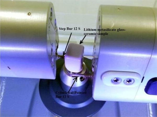
Chairside CAD/CAM milling of a LMGC block using two diamond burs.
Fig. 2.
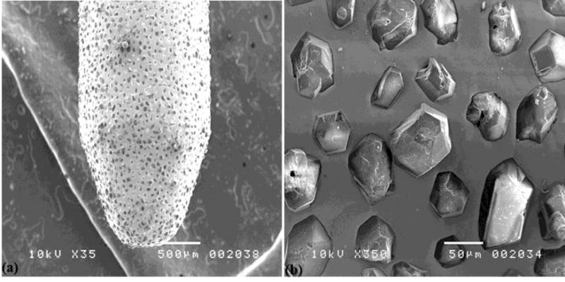
SEM micrographs showing (a) the morphology of a step diamond bur 12 S, (b) diamond abrasives on the bur with approximately 64-μm grit size.
2.3. Surface Process Protocols
After milling of LMGC blocks, the samples were cleaned in acetone and treated by sintering, polishing and glazing to simulate various clinical fabrication processes. These process routes are schematically shown in Fig. 3 and designated as CAD/CAM (i.e., CAD/CAM milling), CAD/CAM-polish, CAD/CAM-sinter, CAD/CAM-polish-sinter, CAD/CAM-sinter-polish, CAD/CAM-sinter-glaze, and CAD/CAM-polish-sinter-glaze processes.
Fig. 3.
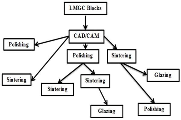
Schematic diagram of all fabrication process routes.
Sintering of milled LMGC samples was carried out in a programed dental furnace (P300, Ivoclar Vivadent, Liechtenstein) at a stand-by temperature of 403 °C. Then, the samples were heated to 770 °C at a heating rate of 60 °C/min and held at the temperature for 10 minutes. After that, they were heated again to 850 °C at a heating rate of 30 °C/min and held for another 10 minutes before cooling to 700 °C. Finally, they were cooled to room temperature.
Dry polishing was conducted manually using a clinical dental handpiece with a grey white rubber diamond bur (Exa Cerapol UM, ISO 658.900.114.525.060, Edenta, Switzerland) operated by a dental clinician. The bur contains dispersed diamond abrasives embedded in a softer elastic matrix (Jefferies, 2007) and is used for intermediate finishing, eliminating scratches and smoothening surfaces as recommended by the manufacturer. Fig. 4 shows the SEM micrograph of the grey-white bur morphology, revealing the average diamond grit size of approximately 60–70 μm. Surfaces were polished at a force of approximately 1 N with the bur rotating at 5,000 rpm to obtain clinically acceptable surface quality.
Fig. 4.
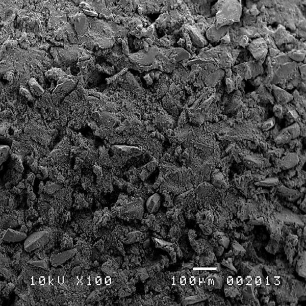
SEM micrograph of the morphology of the grey white rubber diamond bur with approximately 60–70-μm grit size.
Glazing was conducted by firing samples without glass beads in the programed dental furnace at a stand-by temperature of 403 °C. Then the samples were reheated to 820 °C at a heating rate 90 °C/min and held for 10 minutes. Next, they were heated to 840 °C at 30 °C/min heating rate and held for 7 minutes. Finally, the samples were cooled to 700 °C and then to room temperature.
2.4. Surface Characterization
X-ray diffraction was performed to all processed surfaces using an x-ray diffractometer (D/MAX-2500, Rigaku, Japan) with a Cu Kα radiation of 0.15406 nm wave length. The scanning rate employed was 4° min−1 over the incident angles (2θ) in the range of 10–80° at 0.02° scanning step.
All processed surfaces were gold-coated and quantitatively characterized to obtain the arithmetic average roughness, Ra, and the maximum roughness, Rz (De Chiffre et al., 2000) using desktop SEM-assisted morphology analytical software (Phenom-World BV, Netherlands). The software draws lines perpendicular to machining traces and calculates a profile for each measurement line. Fig. 5(a) shows the 3D surface roughness measurement process where measurements were made across three profiles and their average values computed. The cut-off and evaluation lengths were 0.2 mm and 1 mm respectively. Fig. 5(b) shows the 2D surface morphology of Fig. 5(a). On each surface, three roughness measurements were performed to obtain mean values and standard deviations. Each processed surface was also viewed under SEM (JEOL JSM 5410LV, Tokyo, Japan) to study surface fracture, morphology and removal mechanisms.
Fig. 5.
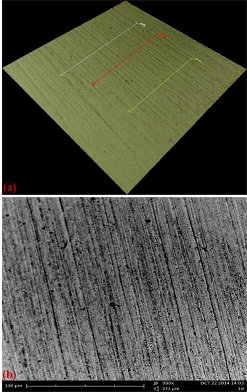
A demonstration of surface roughness measurement using the desktop SEM-assisted morphology analytical software, in which (a) 3D surface roughness measurement with three profiles to be analyzed and (b) 2D surface morphology of (a).
2.5. Statistical Analysis
One-way analysis of variance (ANOVA) was conducted at 95% confidence interval to examine the significance of fabrication processes on the average surface roughness, Ra, and the maximum height, Rz. Paired t test was also performed at 95% confidence to examine the influence of each surface treatment on surface roughness values.
3. Results
3.1. X-ray Diffraction
Fig. 6(a) shows the approximately identical x-ray diffraction pattern for the LMGC surfaces produced in the CAD/CAM and CAD/CAM-polish processes, which is similar to the pattern for the original LMGC surface from the manufacturer (as a reference). All peaks were identified as the lithium catena-silicate (Li2SiO3) or lithium metasilicate crystalline phase, matching the published patterns for LMGC in Alemi et al., 2013 and the Joint Committee on Powder Diffraction Standards (JCPDS)-file No. 30-0766 for lithium metasilicate crystals (Thieme and Rüssel, 2015).
Fig. 6.
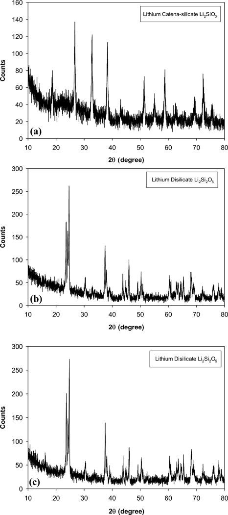
(a) Approximately identical x-ray diffraction pattern for the LMGC surfaces produced in the CAD/CAM and CAD/CAM-polish processes and for the original LMGC surface from the manufacturer (as a reference), (b) Approximately identical x-ray diffraction pattern for the surfaces produced in the CAD/CAM-polish-sinter, CAD/CAM-sinter, and CAD/CAM-sinter-polish processes, (c) Approximately identical x-ray diffraction pattern for the surfaces produced in the CAD/CAM-polish-sinter-glaze and CAD/CAM-sinter-glaze processes.
Fig. 6(b) shows the approximately identical x-ray diffraction pattern for the surfaces produced in the CAD/CAM-polish-sinter, CAD/CAM-sinter, and CAD/CAM-sinter-polish processes. All main peaks were found identical to the theoretical pattern of lithium disilicate crystals published in the JCPDS-file No. 82-2396 (Thieme and Rüssel, 2015). This indicates that LMGC was transformed to LDGC in all three surfaces.
Fig. 6(c) shows the approximately identical x-ray diffraction pattern for the surfaces produced in the CAD/CAM-polish-sinter-glaze and CAD/CAM-sinter-glaze processes. These patterns are similar to Fig. 6(b) and the theoretical pattern of lithium disilicate crystals in the JCPDS-file No. 82-2396 (Thieme and Rüssel, 2015), indicating that the phase transformation from LMGC to LDGC also occurred in these surfaces.
3.2. Surface Roughness
Fig. 7 shows the results of the arithmetic average roughness, Ra, and the maximum roughness, Rz, for different processes and sequences. The smoothest surface with Ra 0.12 ± 0.08 μm and Rz 0.89 ± 0.26 μm was produced in the CAD/CAM-polish-sinter process while the roughest surface with Ra 1.11 ± 0.09 μm and Rz 6.46 ± 0.61 μm was generated in the CAD/CAM-milling process. The moderate roughness with Ra 0.76 ± 0.08 μm and Rz 4.03 ± 0.27 μm was yielded in the CAD/CAM-polish process, which is similar to the surface with Ra 0.70 ± 0.1 μm and Rz 3.75 ± 0.09 μm obtained in the CAD/CAM-sinter-glaze process. The improved surfaces were generated in the CAD/CAM-sinter process with Ra 0.58 ± 0.07 μm and Rz 0.89 ± 0.26 μm. It was followed by the CAD/CAM-sinter-polish process with Ra 0.42 ± 0.12 μm and Rz 2.54 ± 0.88 μm and the CAD/CAM-polish-sinter-glaze process with Ra 0.25 ± 0.01 μm and Rz 1.55 ± 0.08 μm.
Fig. 7.
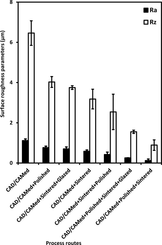
Arithmetic mean roughness, Ra, and maximum roughness, Rz, versus different process routes. Each data point is the mean value of three profiles on each processed surface; the error bars correspond to ± one standard deviation for the three profiles.
Both the average roughness Ra and the maximum roughness Rz were significantly influenced by fabrication processes (p < 0.05). Table 1 summarizes all p-values of paired t-tests for all fabrication processes. Both polishing and sintering significantly improved the roughness Ra and Rz values obtained in milling (p < 0.05). Further sintering of the polished surface also significantly reduced both Ra and Rz values (p < 0.05). Further polishing of the sintered surface only significantly improved the Ra values (p < 0.05) but did not significantly change Rz values (p > 0.05). Glazing did not significantly improve either Ra (p > 0.05) or Rz (p > 0.05) obtained in the sintering and the polishing-sintering processes.
Table 1.
Summary of the p-values of all paired t-tests for Ra and Rz values of all paired fabrication processes.
| Surface treatments |
p-value
|
|
|---|---|---|
| Ra (μm) | Rz (μm) | |
| CAD/CAMed versus CAD/CAMed-polished | p < 0.05 | p < 0.05 |
| CAD/CAMed-versus CAD/CAMed-sintered | p < 0.05 | p < 0.05 |
| CAD/CAMed-polished versus CAD/CAMed-polished-sintered | p < 0.05 | p < 0.05 |
| CAD/CAMed-sintered versus CAD/CAMed-sintered-polished | p < 0.05 | p > 0.05 |
| CAD/CAMed-sintered versus CAD/CAMed-sintered-glazed | p > 0.05 | p > 0.05 |
| CAD/CAMed-polished-sintered versus CAD/CAMed-polished-sintered-glazed | p > 0.05 | p > 0.05 |
3.3. Surface Morphology
Fig. 8 shows the CAD/CAM-milled LMGC surface morphology. Machining grooves and traces scratched by diamond abrasives are detailed in Fig. 8(a). Localized irregular fractures and cracks, and pulverized/smeared areas caused by shear bands are shown in Fig. 8(b). Pulverized or smeared areas with accumulated microchips on the highly fractured areas are revealed in Fig. 8(c). Fig. 9 shows the LMGC surface morphology produced in the CAD/CAM-polish process. Fig. 9(a) shows that polishing smoothened milling traces and scratches, and produced residual pulverized debris and glassy networks. Fig. 9(b) details the glassy networks.
Fig. 8.
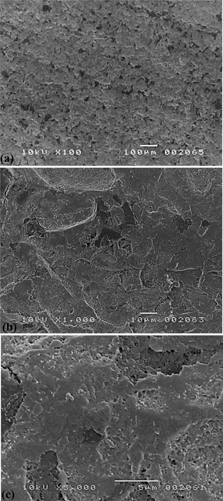
SEM micrographs of the LMGC surface produced in the CAD/CAM process revealing (a) milling traces, fractures and shear band-induced pile-ups leading to the material pulverization, (b) details of surface fractures, and (c) details of pulverized/smeared areas.
Fig. 9.
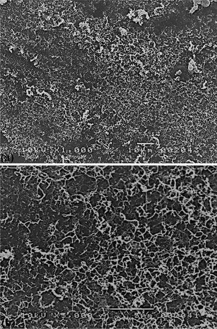
SEM micrographs of the LMGC surface produced in the CAD/CAM-polish process revealing (a) smootherned milling traces and residual debris, and (b) details of glassy networks.
Fig. 10 shows the LDGC surface morphology produced in the CAD/CAM-sinter process, on which the large scale fractures on the milled surface in Fig. 8 disappeared. Fig. 10(a) shows the bulging of the milled surface due to the sintering-induced phase transformation from LMGC to LDGC, resulting in significantly improved surface roughness than the CAD/CAM-milled surface in Fig. 8. Details of the bulged surface in Fig. 10(b) reveal microcracks, which indicate that the sintering cannot completely heal milling-induced surface damage.
Fig. 10.
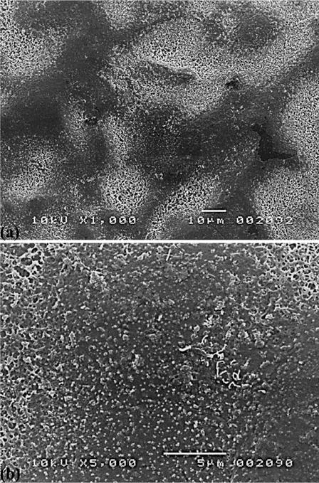
SEM micrographs of the LDGC surface produced in the CAD/CAM-sinter process, showing (a) the bulging of the milled surface and (b) details of the bulged surface.
Fig. 11 shows the LDGC surface morphology produced in the CAD/CAM-sinter-glaze process. Fig. 11(a) shows that the glazing has resulted in the recovery of the bulged surface prodcued in the CAD/CAM-sinter process in Fig. 10, and made the surface look smoother. Fig. 11(b) reveals the residual pulverized debris in the form of very fine particles at the micro or submicro scales.
Fig. 11.
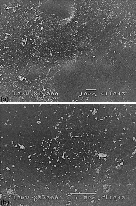
SEM micrographs of the LDGC surface produced in the CAD/CAM-sinter-glaze process demonstrating (a) residual pulverized debris and (b) details of these powdered debris.
Fig. 12 shows the LDGC surface morphology produced in the CAD/CAM-sinter-polish process. Polishing traces, scratches and fractures are visible in Fig. 12(a). Localised fractures, enlarged debris and smeared areas are detailed in Fig. 12(b). These indicate the polishing after sintering did not significantly improve surface morphology.
Fig. 12.
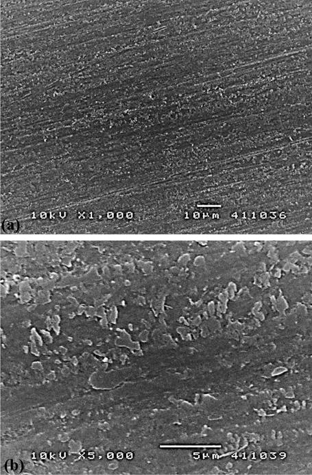
SEM micrographs of the LDGC surface produced in the CAD/CAM-sinter-polish process showing (a) machining traces, scratches and fractures and (b) details of localized fracture, enlarged debris and smeared areas.
Fig. 13 shows the LDGC surface morphology fabricated in the CAD/CAM-polish-sinter process, which has the very smooth surface texture without visible machining traces and phase-transformation induced crystal bulging. This may be attributable to the combined action of polishing and sintering processes on the milled CAD/CAMed surface. Fig. 14 shows the LDGC surface morphology produced in the CAD/CAM-polish-sinter-glaze process. It was similar to the very fine surface produced in the CAD/CAM-polish-sinter process in Fig. 13. However, adhesion of fine particle debris was observed on the finally glazed surface (Fig. 14(b)).
Fig. 13.
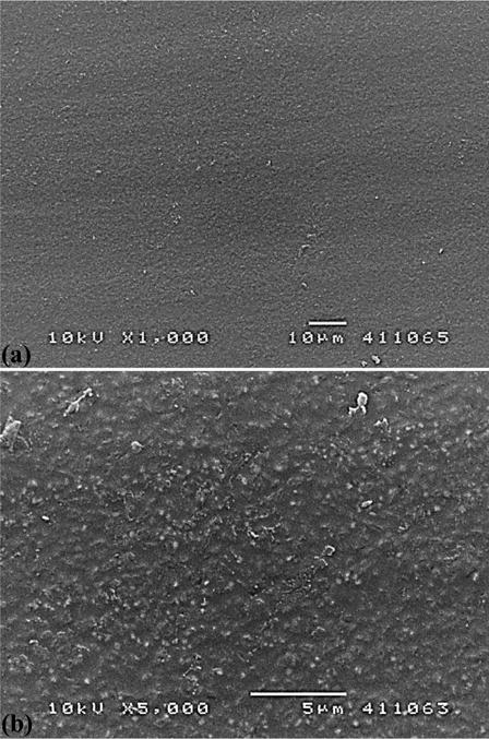
SEM micrographs of the LDGC surface produced in the CAD/CAM-polish-sinter process revealing (a) a very smooth surface texture and (b) details of the smooth surface without visible defects.
Fig. 14.
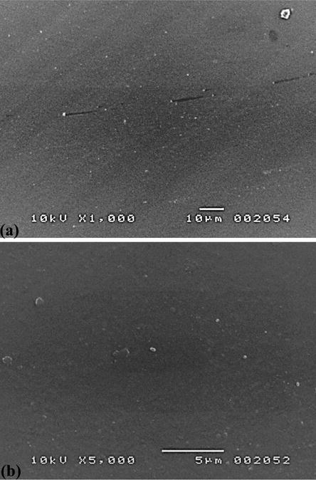
SEM micrographs of the LDGC surface produced in the CAD/CAM-polish-sinter-glaze process showing (a) a very fine surface similar to the surface in Fig. 13(a) and (b) details of the surface with fine particle debris.
4. Discussion
This study focused on the phase transformation, roughness and surface morphology in CAD/CAM-milling, sintering, polishing and glazing of LMGC and LDGC for dental restorations.
The identical x-ray diffraction patterns (Fig. 6(a)) on the surfaces produced in CAD/CAM and CAD/CAM-polish processes indicate that simply milling and subsequent polishing did not cause any phase transformation of the original main crystal phase of lithium metasilicate. The identical x-ray diffraction patterns (Figs. 6(b) and 6(c)) on the surfaces produced in CAD/CAM-polish-sinter, CAD/CAM-sinter, CAD/CAM-sinter-polish, CAD/CAM-polish-sinter-glaze and CAD/CAM-sinter-glaze processes prove that only sintering can transform lithium metasilicate to lithium disilicate. Glazing did not cause new phase transformations, suggesting that sintering of LMGC produced highly stabilized lithium disilicate crystals in LDGC, which has the improved strength to 400 GPa (Denry and Holloway, 2010).
The choice of average and maximum surface roughness parameters (Ra and Rz) in Fig. 7 was based on their frequent use as surface texture characterization parameters that allow comparison with previously published work (De Chiffre et al., 2000). Different process routes yielded a large range of roughness values with Ra 0.12–1.11 μm and Rz 0.89–6.46 μm. Such values are comparable with those of the ground-polished surfaces of LDGC with Ra 0.7 μm (Kou et al., 2006) and glazed LDGC with Ra 0.64 ± 0.014 μm (Boaventura et al., 2013).
The surface fracture on the CAD/CAM-milled LMGC was featured by the SEM micrographs in Fig. 8, which was associated with greatest surface roughness in Fig. 7. This can be attributed to the diamond penetrating, ploughing and scratching of LMGC surfaces in milling, resulting in lateral fracture and localized heat (Jefferies, 2007). Repeated surface fractures also resulted in the material pulverization and created smeared surface defects, which were the consequence of the intergranular and/or transgranular microcracking. These microcracks originated from localized shear stress fields, which were superimposed by hydrostatic compressive stresses in diamond-material contact zones (Zhang and Howes, 1994). The evidence of the transgranular micro-cracking was observed clearly as lithium metasilicate crystals fragmented into micro-sized ceramic grains in Fig. 8(c). The pulverized surface in Fig. 8(a) emanated from surface and subsurface shear bands that were reported in our earlier investigation as the main deformation in nanoindentation of LMGC (Alao and Yin, 2015). Shear bands can form the plastic instability that localizes large shear strains in relatively thin bands during the material deformation process (Greer et al., 2013). They can represent the material plastic deformation or serve as crack-initiating sites (Sergueeva et al., 2005). In milling, shear bands might have initiated microcracking through extensions of subsurface shear bands into underlying tensile matrices or from stress concentration sites at intersections of shear bands (Alao and Yin, 2015). Thus, the machining grooves in Fig. 8(a) might represent large fragmented shear strains which melted unto the surface due to machining-induced high temperatures, roughening the surface (Fig. 7).
Polishing of CAD/CAM-milled LMGC resulted in significant reductions of both surface roughness Ra and Rz (Fig. 7, Table 1). This indicates that polishing effectively smoothened milling traces and scratches of LMGC by abrasive wear mechanism (Fig. 9). The mechanical energy was transferred from abrasives to the LMGC material, removing or displacing the material (Evans et al., 2003; Jefferies, 2007). Meanwhile, polishing formed debris and produced glassy networks shown in Fig. 9.
Sintering of CAD/CAM-milled surfaces (Fig. 10) also significantly reduced the Ra and Rz roughness (Fig. 7 and Table 1), ascribing to the LMGC-LDGC phase transformation (Fig. 6). Sintering might have also caused the relaxation of machining-induced mechanical residual stresses (Zhang and Howes, 1994), which also contributed to the smoothening of milled surfaces (Fig. 10). It might have also generated thermal stresses (Denry, 2013), that can restrict the thermal expansion of milled surfaces and lead to the surface bulging (Fig. 10).
The insignificantly different Rz but significantly different Ra values (Table 1) produced in CAD/CAM-sinter (Fig. 10) and CAD/CAM-sinter-polish (Fig. 12) processes need an in-depth analysis. The maximum roughness Rz generally represents the largest peak-to-valley surface defect size (Cook, 2006) and can be used as a measure of the subsurface damage depth in ceramic grinding and lapping processes (Li et al., 2008). Consequently, polishing after sintering was unable to remove surface peaks and valleys of milling-induced ploughing grooves or scratches due to the high strength of sintering-transformed LDGC. Instead, it only smoothened the average profile to decrease average Ra. Therefore, polishing needs to be conducted prior to sintering. Otherwise, polishing of sintered surfaces requires the usage of high-stiffness polishing media in multiple-step processes with finer abrasives to improve the roughness and transit the brittle-ductile removal (Schmidt and Weigl, 2000; Yin et al., 2007). Interactions of finer abrasives with work materials are dominated by normal forces resulting from negative rake angles and small undeformed chip thicknesses in abrasive-material contact regions (Alao and Konneh, 2012; Evans et al., 2003). These high rake angles permit necessary hydrostatic pressures/temperatures to enable plastic deformation to occur (Evans et al., 2003). However, these multiple procedures would remarkably increase manufacturing time and cost for restorations (Steiner et al., 2015).
The CAD/CAM-polish-sinter process (Fig. 13) produced the lowest roughness, in which polishing easily removed milling traces and scratches of weak LMGC and the subsequent sintering complemented the polishing further for roughness reduction and phase-transformed strength increase. The yielded roughness (Ra = 0.12 ± 0.08 μm) was lower than the threshold roughness (Ra = 0.20 μm) for bacterial plaque retention (Bollen et al., 1997), suggesting that the bacteria accumulation is unlikely to occur. Further, no second step polishing with finer grits is needed for structure retention and shininess. Thus, this process route appears to be the most practical and cost effective.
The subsequent glazing of the CAD/CAMed-polished-sintered surfaces (Fig. 14) could not further improve the roughness (Table 1 and Fig. 7), which is in agreement with that some finishing techniques can obtain surfaces equivalent to glaze-fired ceramic surfaces (Tholt et al., 2006). Meanwhile, glazing at a high temperature might have induced the thermal deformation in LDGC (Denry and Holloway, 2004), which might not be detrimental to the mechanical strength (Cattell et al., 2002; Denry and Holloway, 2004; Wen et al., 2007). Nevertheless, glazing slightly increased the surface roughness above the bacterial retention threshold (Bollen et al., 1997), implying an increased possibility of bacteria accumulation. Thus, glazing should be eliminated to polished-sintered surfaces. In addition, thermal stresses induced by glazing (Fig. 11) might have restricted the thermal expansion of bulged sintered surfaces. This could have caused sufficient hydrostatic compressive stresses to recompact surfaces, which generated powder debris to increase the roughness (Fig. 7). Thus, glazing improved neither roughness Ra nor Rz of CAD/CAMed-sintered surfaces (Table 1) because of the bursting of bulged surfaces to powders.
Comparing all processes, the CAD/CAM-polish-sinter process route proved to be the optimized procedure, meeting clinical dental standards and eliminating secondary polishing and glazing for time and cost effectiveness. Therefore, this route is proposed for the production of LDGC restorations as schematically described in Fig. 15. The CAD/CAM-milling of LMGC first generates rough restorative profiles. Polishing is only conducted on occlusal, facial and lingual surfaces. Then, sintering is applied to strengthen the material. Intaglio surfaces produced in the CAD/CAM-sinter process can be etched by hydrofluoric acid to roughen surfaces for cementation (Borges et al., 2003; Kelly, 1997). It is likely that this optimized procedure may benefit both dental patients and clinicians who routinely use LDGC restorations and expect them long-lasting. Given that the long-term (after 15 years) survival rate for LDGC crowns achieved only 81.9% (van den Breemer et al., 2017), continuing efforts for improvement are needed. An important thrust for these efforts is to foster a more analytical engineering approach to clinical manufacturing of restorations. This study has provided a rational understanding of the optimized clinical procedure for LDGC restorations which can be practically utilized in restorative dentistry.
Fig. 15.
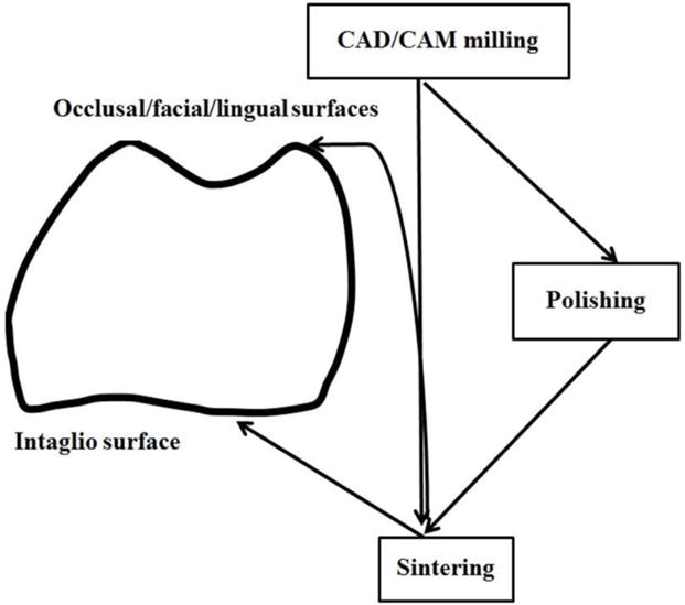
The optimized fabrication procedure for occlusal/facial/lingual and intaglio (cementation) surfaces in LDGC restorations
5. Conclusions
This work investigated the surface fracture, roughness and morphology, phase transformations, and material removal mechanisms of LMGC/LDGC produced in CAD/CAM milling, sintering, polishing and glazing. The CAD/CAM-milling process produced the coarsest surface roughness due to extensive brittle cracking and pulverization. Polishing of CAD/CAM-milled LMGC efficiently improved roughness by wearing the milled traces and scratches through abrasive mechanical actions. Sintering transformed LMGC to LDGC with increased strength. The subsequent glazing did not change the stabilized LDGC but might have induced additional thermal stresses leading to further deformation. Polishing of LDGC did not significantly reduce surface roughness because the high-strength LDGC makes the material difficult to machine. The CAD/CAM-polish-sinter process produced the best roughness, which fulfilled clinical requirements for cost effectiveness, time efficiency, and surface quality for occlusal functions and bacterial plaque retention. Further studies will be conducted to determine the reliability of the proposed process route for LDGC restorations and establish the relations between their surface integrity and fatigue behavior.
Acknowledgments
The authors thank Drs. Shane Askew and Kevin Blake of the Advanced Analytical Center and Mr. Kevin Chong of College of Medicine & Dentistry at James Cook University (JCU) for experimental assistance; Mr. Jim Ruddy of Ivoclar Vivadent, Australia for providing e.max CAD blocks; and Mr. Matthew Batty of Sirona, Australia for offering CAD/CAM technical support. A.-R.A acknowledges the JCU PhD Scholarship (JCU IPRS). The work was supported by the JCU Collaboration Grants Scheme; the Australia-China Science and Research Fund from the Department of Industry, Innovation, Climate Change, Science, Research and Tertiary Education, Australia (Grant No. ACSRF GMB 12029); the National Natural Science Foundation of China (Grant No. 51375335); and the United States National Institutes of Health, National Institute of Dental and Craniofacial Research (Grant No. R01DE017925 and Grant No. R01DE026772).
Footnotes
Publisher's Disclaimer: This is a PDF file of an unedited manuscript that has been accepted for publication. As a service to our customers we are providing this early version of the manuscript. The manuscript will undergo copyediting, typesetting, and review of the resulting proof before it is published in its final citable form. Please note that during the production process errors may be discovered which could affect the content, and all legal disclaimers that apply to the journal pertain.
References
- Alao AR, Konneh M. Surface finish prediction models for precision grinding of silicon. Int J Adv Manuf Technol. 2012;58:949–967. [Google Scholar]
- Alao AR, Stoll R, Song XF, Miyazaki T, Hotta Y, Shibata Y, Yin L. Surface quality of yttria-stabilized tetragonal zirconia polycrystal in CAD/CAM milling, sintering, polishing and sandblasting processes. J Mech Behav Biomed Mater. 2017;65:102–116. doi: 10.1016/j.jmbbm.2016.08.021. [DOI] [PubMed] [Google Scholar]
- Alao AR, Yin L. Nano-mechanical behavior of lithium metasilicate glass-ceramic. J Mech Behav Biomed Mater. 2015;49:162–174. doi: 10.1016/j.jmbbm.2015.05.002. [DOI] [PubMed] [Google Scholar]
- Apel E, Deubener J, Bernard A, Höland M, Müller R, Kappert H, Rheinberger V, Höland W. Phenomena and mechanisms of crack propagation in glass-ceramics. J Mech Behav Biomed Mater. 2008;1:313–325. doi: 10.1016/j.jmbbm.2007.11.005. [DOI] [PubMed] [Google Scholar]
- Beuer F, Schweiger J, Eichberger M, Kappert HF, Gernet W, Edelhoff D. High-strength CAD/CAM-fabricated veneering material sintered to zirconia copings- A new fabrication mode for all-ceramic restorations. Dent Mater. 2009;25:121–128. doi: 10.1016/j.dental.2008.04.019. [DOI] [PubMed] [Google Scholar]
- Boaventura JMC, Nishida R, Elossais AA, Lima DM, Reis JMSN, Campos EA, de Andrade MF. Effect finishing and polishing procedures on the surface roughness of IPS Empress 2 ceramic. Acta Odontol Scand. 2013;71:438–443. doi: 10.3109/00016357.2012.690570. [DOI] [PMC free article] [PubMed] [Google Scholar]
- Bollen CML, Lambrechts P, Quirynen M. Comparison of surface roughness of oral hard materials to the threshold surface roughness for bacterial plaque retention: A review of the literature. Dent Mater. 1997;13:258–269. doi: 10.1016/s0109-5641(97)80038-3. [DOI] [PubMed] [Google Scholar]
- Borges GA, Sophr AM, de Goes MF, Sobrinho LC, Chan DCN. Effect of etching and airborne abrasion on the microstructure of different dental ceramics. J Prosthet Dent. 2003;89:479–488. doi: 10.1016/s0022-3913(02)52704-9. [DOI] [PubMed] [Google Scholar]
- Brunot-Gohin C, Duval JL, Azogui EE, Jannetta R, Pezron I, Laurent-Maquin D, Gangloff SC, Egles C. Soft tissue adhesion of polished versus glazed lithium disilicate ceramic for dental applications. Dent Mater. 2013;29:e205–e212. doi: 10.1016/j.dental.2013.05.004. [DOI] [PubMed] [Google Scholar]
- Bühler-Zemp P, Völkel T. IPS e.max CAD Scientific documentation. Ivoclar Vivadent. 2005:1–16. [Google Scholar]
- Cattell MJ, Palumbo RP, Knowles JC, Clarke RL, Samarawickrama DYD. The effect of veneering and heat treatment on the flexural strength of Empress® 2 ceramics. J Dent. 2002;30:161–169. doi: 10.1016/s0300-5712(02)00013-1. [DOI] [PubMed] [Google Scholar]
- Cook RF. Strength and sharp contact fracture of silicon. J Mater Sci. 2006;41:841–872. [Google Scholar]
- Currana P, Cattani-Lorenteb M, Wiskottb HWA, Durualb S, Scherrerb SS. Grinding damage assessment for CAD-CAM restorative materials. Dent Mater. 2017;33:294–308. doi: 10.1016/j.dental.2016.12.004. [DOI] [PubMed] [Google Scholar]
- De Chiffre L, Lonardo P, Trumpold H, Lucca DA, Goch G, Brown CA, Raja J, Hansen HN. Quantitative characterization of surface texture. CIRP Ann-Manuf Technol. 2000;49:635–652. [Google Scholar]
- De Jager Feilzer AJ, Davidson CL. The influence of surface roughness on porcelain strength. Dent Mater. 2000;16:381–388. doi: 10.1016/s0109-5641(00)00030-0. [DOI] [PubMed] [Google Scholar]
- Della Bona A, Kelly JR. The clinical success of all-ceramic restorations. J Am Dent Assoc. 2008;139(9 suppl):8S–13S. doi: 10.14219/jada.archive.2008.0361. [DOI] [PubMed] [Google Scholar]
- Denry I. How and when does fabrication damage adversely affect the clinical performance of ceramic restorations? Dent Mater. 2013;29:85–96. doi: 10.1016/j.dental.2012.07.001. [DOI] [PubMed] [Google Scholar]
- Denry I, Holloway JA. Effect of post-processing heat treatment on the fracture strength of a heat-pressed dental ceramic. J Biomed Mater Res Part B: Appl Biomater. 2004;68B:174–179. doi: 10.1002/jbm.b.20018. [DOI] [PubMed] [Google Scholar]
- Denry I, Holloway JA. Ceramics for dental applications: A review. Materials. 2010;3:351–368. [Google Scholar]
- El-Meliegy E, van Noort R. Glasses and glass ceramics for medical applications. Springer; New York: 2012. [Google Scholar]
- Evans CJ, Paul E, Dornfeld D, Lucca DA, Byrne G, Tricard M, Klocke F, Dambon O, Mullany BA. Material removal mechanisms in lapping and polishing. CIRP Ann-Manuf Technol. 2003;52:611–633. [Google Scholar]
- Fasbinder DJ, Dennison JB, Heys D, Neiva G. A clinical evaluation of chairside lithium disilicate CAD/CAM crowns: A two-year report. J Am Dent Assoc. 2010;141:10s–14s. doi: 10.14219/jada.archive.2010.0355. [DOI] [PubMed] [Google Scholar]
- Greer AL, Cheng YQ, Ma E. Shear bands in metallic glasses. Mater Sci Eng R. 2013;74:71–132. [Google Scholar]
- Guess PC, Zhang Y, Kim JW, Rekow ED, Thompson VP. Damage and reliability of Y-TZP after cementation surface treatment. J Dent Res. 2010;89:592–596. doi: 10.1177/0022034510363253. [DOI] [PMC free article] [PubMed] [Google Scholar]
- Höland W, Apel E, van ‘t Hoen Ch, Rheinberger V. Studies of crystal phase formations in high-strength lithium disilicate glass-ceramics. J Non-Crystalline Solid. 2006a;352:4041–4050. [Google Scholar]
- Höland W, Schweiger M, Frank M, Rheinberger V. A comparison of the microstructure and properties of the IPS Empress 2 and IPS Empress glass-ceramics. J Biomed Mater Res B Appl Biomater. 2000;53:297–303. doi: 10.1002/1097-4636(2000)53:4<297::aid-jbm3>3.0.co;2-g. [DOI] [PubMed] [Google Scholar]
- Höland W, Rheinberger V, Apel E, van’t Hoen C, Höland M, Dommann A, Obrecht M, Mauth C, Graf-Hausner U. Clinical applications of glass-ceramics in dentistry. J Mater Sci: Mater Med. 2006b;17:1037–1042. doi: 10.1007/s10856-006-0441-y. [DOI] [PubMed] [Google Scholar]
- Jefferies SR. Abrasive finishing and polishing in restorative dentistry: A state-of-the-art review. Dent Clin North Am. 2007;51:379–397. doi: 10.1016/j.cden.2006.12.002. [DOI] [PubMed] [Google Scholar]
- Kelly JR. Ceramics in restorative and prosthetic dentistry. Ann Rev Mater Sci. 1997;27:443–468. [Google Scholar]
- Kelly JR. Dental ceramics: what is this stuff anyway? J Am Dent Assoc. 2008;139:4s–7s. doi: 10.14219/jada.archive.2008.0359. [DOI] [PubMed] [Google Scholar]
- Kern M, Sasse M, Wolffart S. Ten-year outcome of three-unit fixed dental prostheses made from monolithic lithium disilicate ceramic. J Am Dent Assoc. 2012;143:234–240. doi: 10.14219/jada.archive.2012.0147. [DOI] [PubMed] [Google Scholar]
- Kou W, Molin M, Sjögren G. Surface roughness of five different dental ceramic core materials after grinding and polishing. J Oral Rehabil. 2006;33:117–124. doi: 10.1111/j.1365-2842.2006.01546.x. [DOI] [PubMed] [Google Scholar]
- Li S, Wang Z, Wu Y. Relationship between subsurface damage and surface roughness of optical materials in grinding and lapping processes. J Mater Process Technol. 2008;205:34–41. [Google Scholar]
- Lin WS, Harris BT, Morton D. Trial insertion procedure for milled lithium disilicate restorations in the precrystallized state. J Prosthet Dent. 2012;107:59–62. doi: 10.1016/S0022-3913(12)60020-1. [DOI] [PubMed] [Google Scholar]
- Luthardt RG, Holzhüter MS, Rudolph H, Herold V, Walter MH. CAD/CAM-machining effects on Y-TZP zirconia. Dent Mater. 2004;20:655–662. doi: 10.1016/j.dental.2003.08.007. [DOI] [PubMed] [Google Scholar]
- Marquardt P, Strub JR. Survival rates of IPS empress 2 all-ceramic crowns and fixed partial dentures: results of a 5-year prospective clinical study. Quintessence Int. 2006;37:253–259. [PubMed] [Google Scholar]
- Mores RT, Borba M, Corazza PH, Della Bona A, Benetti P. Influence of surface finishing on fracture load and failure mode of glass ceramic crowns. J Pros Dent. 2017 doi: 10.1016/j.prosdent.2016.12.012. In press, https://doi.org/10.1016/j.prosdent.2016.12.012. [DOI] [PubMed]
- Peng Z, Rahman MIA, Zhang Y, Yin L. Wear behavior of pressable lithium disilicate glass ceramic. J Biomed Mater Res Part B Appl Biomater. 2016;104B:968–978. doi: 10.1002/jbm.b.33447. [DOI] [PMC free article] [PubMed] [Google Scholar]
- Reich S, Endres L, Weber C, Wiedhahn K, Neumann P, Schneider O, Rafai N, Wolfart S. Three-unit CAD/CAM-generated lithium disilicate FDPs after a mean observation time of 46 months. Clin Oral Invest. 2014;17:2171–2178. doi: 10.1007/s00784-014-1191-8. [DOI] [PubMed] [Google Scholar]
- Reich S, Schierz O. Chair-side generated posterior lithium disilicate crowns after four years. Clin Oral Invest. 2013;17:1765–1772. doi: 10.1007/s00784-012-0868-0. [DOI] [PubMed] [Google Scholar]
- Rekow ED, Silva NRFA, Coelho PG, Zhang Y, Guess P, Thompson VP. Performance of dental ceramics: Challenges for improvements. J Dent Res. 2011;90(8):937–952. doi: 10.1177/0022034510391795. [DOI] [PMC free article] [PubMed] [Google Scholar]
- Rekow D, Thompson VP. Near-surface damage-a persistent problem in crowns obtained by computer-aided design and manufacturing. Proc Inst Mech Eng H. 2005;219:233–243. doi: 10.1243/095441105X9363. [DOI] [PubMed] [Google Scholar]
- Schmidt C, Weigl P. Machinability of IPS Empress 2 framework ceramic: potential for ceramic dentures. J Biomed Mater Res (Appl Biomater) 2000;53:348–352. doi: 10.1002/1097-4636(2000)53:4<348::aid-jbm8>3.0.co;2-0. [DOI] [PubMed] [Google Scholar]
- Serbena FC, Zanotto ED. Internal residual stresses in glass-ceramics: A review. J Non-Cryst Solids. 2012;358:975–984. [Google Scholar]
- Sergueeva AV, Mara NA, Kuntz JD, Lavernia EJ, Mukherjee AK. Shear band formation and ductility in bulk metallic glass. Philos Mag. 2005;85:2671–2687. [Google Scholar]
- Song XF, Ren HT, Yin L. Machinability of lithium disilicate glass ceramic in in vitro dental diamond bur adjusting process. J Mech Behav Biomed Mater. 2016;53:78–92. doi: 10.1016/j.jmbbm.2015.08.003. [DOI] [PubMed] [Google Scholar]
- Steiner R, Beier US, Heiss-Kisielewsky I, Engelmeier R, Dumfahrt H, Dhima M. Adjusting dental ceramics: An in vitro evaluation of the ability of various ceramic polishing kits to mimic glazed dental ceramic surface. J Prosthet Dent. 2015;113:616–622. doi: 10.1016/j.prosdent.2014.12.007. [DOI] [PubMed] [Google Scholar]
- Swain MV. Unstable cracking (chipping) of veneering porcelain on all-ceramic crowns and fixed partial dentures. Acta Biomater. 2009;5:1668–1677. doi: 10.1016/j.actbio.2008.12.016. [DOI] [PubMed] [Google Scholar]
- Thieme K, Rüssel C. Nucleation and growth kinetics and phase analysis in zirconia-containing lithium disilicate glass. J Mater Sci. 2015;50:1488–1499. [Google Scholar]
- Tholt B, Miranda-Júnior WG, Prioli R, Thompson J, Oda M. Surface roughness in ceramics with different finishing techniques using atomic force microscope and profilometer. Oper Dent. 2006;31–4:442–449. doi: 10.2341/05-54. [DOI] [PubMed] [Google Scholar]
- Ulutan D, Ozel T. Machining induced surface integrity in titanium and nickel alloys: A review. Int J Mach Tools Manuf. 2011;51:250–280. [Google Scholar]
- Valenti M, Valenti A. Retrospective survival analysis of 261 lithium disilicate crowns in a private general practice. Quintessence Int. 2009;40:573–579. [PubMed] [Google Scholar]
- van den Breemer CRG, Vinkenborg C, van Pelt H, Edelhoff D, Cune MS. The clinical performance of monolithic lithium disilicate posterior restorations after 5, 10, and 15 years: a retrospective case series. Int J Prosthodont. 2017;30:62–65. doi: 10.11607/ijp.4997. [DOI] [PubMed] [Google Scholar]
- Wen G, Zheng X, Song L. Effects of P2O5 and sintering temperature on microstructure and mechanical properties of lithium disilicate glass-ceramics. Acta Mater. 2007;55:3583–3591. [Google Scholar]
- Whitehead SA, Shearer AC, Watts DC, Wilson NHF. Comparison of methods for measuring surface roughness of ceramic. J Oral Rehabil. 1995;22:421–427. doi: 10.1111/j.1365-2842.1995.tb00795.x. [DOI] [PubMed] [Google Scholar]
- Yin L, Han YG, Song XF, Wang H. Effect of diamond burs on process and damage involving in vitro dental resurfacing of a restorative porcelain. J Phys D: Appl Phys. 2007;40:5291–5300. [Google Scholar]
- Zhang B, Howes TD. Material-removal mechanisms in grinding ceramics. CIRP Ann-Manuf Technol. 1994;43:305–308. [Google Scholar]
- Zhang Y, Kim JW, Bhowmick S, Thompson VP, Rekow ED. Competition of fracture mechanisms in monolithic dental ceramics: Flat model system. J Biomed Mater Res Part B: Appl Biomater. 2009;88B:402–411. doi: 10.1002/jbm.b.31100. [DOI] [PMC free article] [PubMed] [Google Scholar]
- Zhang Y, Lee JJW, Srikanth R, Lawn BR. Edge Chipping and Flexural Resistance of Monolithic Ceramics. Dent Mater. 2013a;29:1201–1208. doi: 10.1016/j.dental.2013.09.004. [DOI] [PMC free article] [PubMed] [Google Scholar]
- Zhang Y, Sailer I, Lawn BR. Fatigue of Dental Ceramics. J Dent. 2013b;41:1135–1147. doi: 10.1016/j.jdent.2013.10.007. [DOI] [PMC free article] [PubMed] [Google Scholar]


