Abstract
Multi-reflection Bragg coherent diffraction imaging has the potential to allow 3D resolved measurements of the full lattice strain tensor in specific micro-crystals. Until now such measurements were hampered by the need for laborious, time-intensive alignment procedures. Here we demonstrate a different approach, using micro-beam Laue X-ray diffraction to first determine the lattice orientation of the micro-crystal. This information is then used to rapidly align coherent diffraction measurements of three or more reflections from the crystal. Based on these, 3D strain and stress fields in the crystal are successfully determined. This approach is demonstrated on a focussed ion beam milled micro-crystal from which six reflections could be measured. Since information from more than three independent reflections is available, the reliability of the phases retrieved from the coherent diffraction data can be assessed. Our results show that rapid, reliable 3D coherent diffraction measurements of the full lattice strain tensor in specific micro-crystals are now feasible and can be successfully carried out even in heavily distorted samples.
Keywords: Bragg coherent diffraction imaging, Micro-beam Laue diffraction, Ion implantation, Strain tensor measurement
1. Introduction
Bragg Coherent Diffraction Imaging (BCDI) has emerged as a powerful technique for the non-destructive probing of morphology and lattice distortions in sub-micron single crystals (Robinson & Harder, 2009). It uses a coherent, monochromatic X-ray beam to fully illuminate the single-crystalline domain under study. An oversampled 3D reciprocal space map, or 3D coherent X-ray diffraction pattern (CXPD), of one of the crystal reflections is recorded using an area detector placed in the far field. This CXDP corresponds to the square of the amplitude of the Fourier transform of the Bragg electron density in the crystal (Ulvestad, Clark et al., 2015; Robinson et al., 2001). The CXDP cannot be directly inverted, using an inverse Fourier transform, since the phase of the diffracted wave field is not measured. Fortunately, for an oversampled CXDP and given suitable real and reciprocal space constraints, the phase information can be recovered using iterative phase retrieval algorithms (Fienup, 1982). The reconstructed real-space electron density is complex-valued. Its amplitude provides information about electron density, ρ(r), i.e. the shape of the crystal contributing to the CXDP. Its phase, ψ(r), is linked to displacements, u(r), of atoms from their ideal lattice positions in the direction of the scattering vector q. For a particular crystal reflection with associated qhkl the phase is given by ψhkl(r) = qhkl·u(r). Thus BCDI simultaneously provides detailed information about both crystal morphology and lattice distortion. An important advantage over point-probe techniques is that spatial resolution in BCDI is independent of the X-ray beam size. Instead it is governed by the sample scattering power and ultimately only limited by the numerical aperture of the detection system (Clark et al., 2012). 3D spatial resolution of a few 10s of nm has been reported by several authors (Clark et al., 2012, 2015).
Single-reflection BCDI measurements have been used extensively to study strains in micro-crystals. Initial studies concentrated on weakly strained systems, for example as-grown micro-crystals (Robinson et al., 2001; Harder et al., 2007) and lattice-mismatch induced strains (Pfeifer et al., 2006). With the development of more sophisticated phase retrieval codes that account for partial coherence effects and use guided phasing (Clark et al., 2012) the study of more complex systems has become possible. For example the effects of dislocations on crystal growth and dissolution (Clark et al., 2015), as well as charging-induced strains in battery particles, have been studied (Ulvestad, Singer et al., 2015). BCDI has also been used to probe irradiation-induced degradation of bio-crystals (Coughlan et al., 2015, 2017) and catalysis-induced strains in micro-crystals (Ulvestad et al., 2016). Furthermore, by combining BCDI with optical pump, X-ray probe measurements at 4th generation light sources, acoustic phonons (Clark et al., 2013) and transient melting (Clark et al., 2015) have been studied. In all of these measurements only one crystal reflection was measured providing access to the projection of u(r) onto q and hence to only one of the six strain tensor components; the strain along the direction of q. This limited information can make the interpretation of complex strain fields, for example due to crystal defects, ambiguous.
By combining BCDI measurements of 3 or more reflections form the same crystal with linearly independent q vectors, the full lattice displacement field u(r) can be recovered. This in turn can be differentiated to determine the full 3D lattice strain tensor, ε(r), within the crystal. This approach was first demonstrated by Newton et al. on ZnO micro-rods (Newton et al., 2010). Remarkably, since then, while many single reflection BCDI studies have been performed, only one further measurement of multiple reflections from the same sample has been reported (Beitra et al., 2010; Ulvestad, Clark et al., 2015). The reason is that, without prior knowledge of the micro-crystal orientation, a laborious search in reciprocal space is required to find and align two reflections, based on which further reflections can then be found (Beitra et al., 2010). This search can easily occupy several days of experimental time.
Here we propose a new approach: Using micro-beam Laue diffraction we first measure the lattice orientation of the micro-crystal for which BCDI measurements are to be performed. This orientation information allows the rapid alignment of CXDP measurements from multiple reflections of the micro-crystal. We demonstrate this method for the measurement of a gold micro-crystal sculpted using focused ion beam (FIB) milling. For this crystal we reliably reconstruct the full 3D lattice displacement field, the lattice strain tensor and the residual stress tensor due to the ion milling treatment.
2. Experimental methodology
2.1. Sample preparation
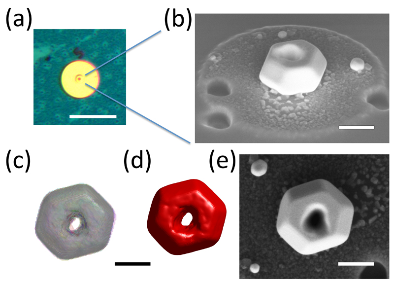
Gold micro-crystals were manufactured by depositing a 2 nm thick layer of titanium, followed by a 20 nm thick layer of gold, on a silicon wafer, using thermal evaporation. Next the sample was annealed (1273 K, 10 hours in air) to dewet the gold film and form micro-crystals. Using scanning electron microscopy (SEM) (Zeiss Auriga), the as-grown crystals were inspected and a crystal of ~1 μm size was selected for this study. FIB was used to clear a 40 μm diameter circle around the crystal (Fig. 1 (a)). This facilitated reliable, unambiguous identification of the specific crystal and ensured that no spurious diffraction peaks, due to nearby crystals, interfered with the measured CXDPs. A single FIB imaging scan (30 kV, 50 pA, 6.8 x 10⁻¹⁵ C/μm2) was used to align an annular FIB milling scan (30 kV, 50 pA, 5 x 10⁻¹⁰ C/μm2) with 2.5 μm inner and 10 μm outer diameter, centered on the crystal of interest. A further milling scan (30 kV, 1 nA, 5 x 10⁻¹⁰ C/μm2) with 8 μm inner and 40 μm outer diameter was used to remove all other gold micro-crystals within a 20 μm radius. Finally a central hole with 200 nm nominal diameter was milled into the crystal (30 kV, 50 pA, 4 x 10⁻¹⁰ C/μm2). High-resolution SEM micrographs of the specimen following these milling steps are shown in Fig. 1. The total time required for SEM imaging and FIB milling of this micro-crystal was ~90 minutes.
Figure 1.
Sample Overview. (a) Optical micrograph of the sample, showing the micro-crystal and the surrounding area cleared using FIB. The scalebar corresponds to 50μm. (b) SEM micrograph of the micro-crystal after FIB milling. The holes near the crystal are locations where adjacent crystals were removed using localised FIB milling. (c) Superimposed morphologies of the micro-crystal recovered from BCDI measurements of six different crystal reflections. Morphologies are rendered semi-transparent to allow examination of their agreement. (d) Mean morphology recovered from all BCDI measurements. (e) High resolution SEM micrograph of the micro-crystal. (c), (d) and (e) are all shown at the same magnification, viewing the sample from the same direction and in the same orientation. Scalebars in (b) – (e) correspond to 500 nm.
To allow accurate and repeatable positioning of the sample on both Laue and BCDI instruments, the sample substrate was mounted on a 1 inch Thorlabs kinematic mount using epoxy.
2.2. Laue diffraction measurements
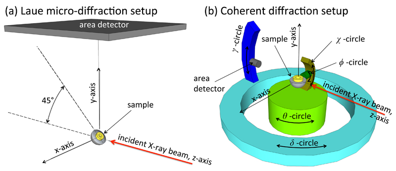
Laue micro-diffraction measurements to determine the orientation of the micro-crystal were carried out at beamline 34-ID-E at the Advanced Photon Source, Argonne National Lab, USA. Fig. 2 (a) shows a schematic of the experimental setup. Detailed descriptions of the beamline are provided elsewhere (Liu et al., 2004, 2011; Hofmann et al., 2013). Briefly, a monochromatic (~10-4 ΔE/E) or polychromatic (5 – 30 keV) X-ray beam, focused to a size of 0.6 x 0.7 μm2 (h x v) by KB mirrors, is delivered to the sample. The sample is positioned in reflection geometry with its surface inclined at a 45° angle to the incident beam, and diffraction patterns are collected on a Perkin Elmer flat panel detector mounted above the sample.
Figure 2.
Schematic of the experimental configurations for Laue diffraction (a) and coherent diffraction experiments (b). Drawings are not to scale. All coordinate systems are right handed. Rotations in (b) are shown in their 0° positions.
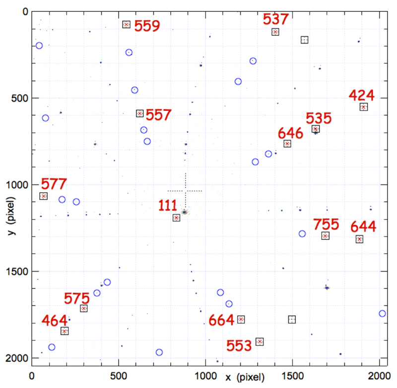
Fluorescence measurements of the gold Lα1 peak (9.713 keV) were used to identify the spatial position of the micro-crystal. Then, switching over to polychromatic beam mode, a Laue diffraction pattern was collected from the crystal (Fig. 3). It shows weak Laue peaks due to the gold micro-crystal and strong diffraction peaks due to the single-crystal silicon substrate. The gold peaks were sufficiently well separated from the silicon peaks that they could be indexed and fitted using the LaueGo software (J.Z. Tischler, tischler@aps.anl.gov). From the refinement, the UB matrix, which provides the direction and radial position of specific hkl reflections, Hhkl, in laboratory coordinates, was determined (Busing & Levy, 1967):
| (1) |
Figure 3.
Laue micro-diffraction pattern collected from the micro-crystal. Square boxes show micro-crystal reflections that were used for orientation determination. The corresponding hkl indices are shown in red. Circles represent locations where further, weaker reflections from the micro-crystal are expected. Other intense peaks in the diffraction pattern belong to the silicon substrate and are not indexed here for clarity.
Since in white beam Laue diffraction only the angular positions of reflections are known, but not the energy at which they occur, the usual constraint of a constant unit cell volume was enforced (Chung & Ice, 1999). The UB matrix determined by Laue diffraction will be referred to as UBLaue. The total time required to align the micro-crystal and collect the Laue data was ~60 minutes. Analysis of the Laue data occupied another ~15 minutes.
2.3. Coherent X-ray diffraction measurements
Coherent diffraction measurements were carried out on beamline 34-ID-C at the Advanced Photon Source, Argonne National Lab, USA. Fig. 2(b) shows the angular degrees of freedom of this instrument with all rotations shown in their zero degree positions. A right-handed coordinate convention was adopted throughout, in contrast to the convention used in the beamline .spec file. To translate from one to the other, the following relationships can be used (where a subscript spec denotes the angles recorded in the .spec file):
| (2) |
The incident, monochromatic X-ray beam (10.2 keV, ~10-4 ΔE/E) was focused to a size of 1.4 x 2.1 μm2 (h x v) at the sample using KB mirrors. By positioning the sample in the back focal plane of the KB mirror and using the central maximum of the focused beam, the plane wave illumination required for BCDI is achieved. Diffraction patterns were recorded on a Medipix2 area detector with a 256 x 256 pixel matrix and a pixel size of 55 μm.
2.4. Sample alignment for coherent diffraction
The critical step for reliable measurement of multiple Bragg reflections from the same crystal is the ability to reliably align the crystal both in position and orientation. An in situ confocal microscope was used to position the micro-crystal within the X-ray beam (Beitra et al., 2010).
For angular alignment of the sample an approximate UB matrix for BCDI measurements, UBBCDI, was calculated based on UBLaue:
| (3) |
Here Rx(45°) represents a 45° rotation matrix about the x-axis required to account for the 45° angle at which the sample is mounted for Laue measurements. From now on we adopt the convention that a rotation matrix Ri(α) represents a right-handed rotation of α degrees about the i axis (x, y, or z).
To enter UBBCDI into the Spec software, the approach of defining a primary and secondary reflection was used. Here two “dummy” reflections were entered, corresponding to the hkl values associated with the lab x (in-plane) and y (normal) directions:
- Primary reflection (surface normal, i.e. y direction): The instrument angles were set to δspec=0°, γspec=20°, θspec=0°, χspec=90°, ϕspec=-10°. The corresponding fractional hkl was determined as follows:
(4) - Secondary reflection (in-plane, i.e. x-direction): The instrument angles were set to δspec=20°, γspec=0°, θspec=10°, χspec=90°, ϕspec=0°. The corresponding fractional hkl was determined as follows:
(5)
Spec was then used to calculate the angular positions at which {111} and {200} reflections from the sample are anticipated. The actual diffraction peaks were reliably found within less than 1° of the calculated positions and were used to refine UBBCDI. In total six reflections from the micro-crystal were aligned: (-111), (1-11), (11-1), (200), (020), (002). The positions of all rotations and translations corresponding to each reflection were stored.
Using this approach we were able to align six reflections from the same micro-crystal in less than an hour. More recent measurements showed that this procedure works reliably for different micro-crystals (requiring at most two hours to align six reflections) and can be routinely used for rapid alignment. This is a vast improvement on previous time-consuming searches of reciprocal space that required prior information about preferential alignment of micro-crystals (Newton et al., 2010; Beitra et al., 2010). Importantly this alignment approach is generally applicable to any randomly oriented crystal.
2.5. Coherent diffraction measurements
CXDPs of each reflection were recorded by rotating the crystal in θ, covering an angular range of -0.2° to 0.2° with respect to the reflection center and recording an image every 0.0025° with an exposure time of 1 s. A sample-to-detector distance of 1.85 m was used. This was chosen by initially positioning the detector to meet the oversampling requirement, and further increasing distance until the diffraction pattern filled the detector matrix. To optimize the signal-to-noise level of the CXDPs, 20 repeated scans of each reflection were measured. To correct for any sample drift during measurements, an automatic angular and position alignment step was carried out before every scan. The multiple scans recorded of each CXDP were aligned to maximize their cross correlation coefficient using a 3D version of the algorithm described by Guizar-Sicairos et al. (Guizar-Sicairos et al., 2008). Scans with a cross-correlation coefficient greater than 0.99 were added to produce the CXDP of a specific reflection. The number of scans included in each CXDP is noted in ‘’ after each reflection: (-111) ‘12’, (1-11) ‘16’, (11-1) ‘17’, (200) ‘9’, (020) ‘12’, (002) ‘14’.
2.6. Phase retrieval
Phase retrieval was performed independently for each reflection and is based on code from previously published work (Clark et al., 2015). A guided phase retrieval approach (Chen et al., 2007) with 20 random starts and 5 generations was used, with a best solution selection based on a sharpness metric. This was previously shown to yield the most truthful reconstructions for strained samples (Clark et al., 2015). A low-to-high resolution phasing scheme was employed, phasing low spatial resolution data in the first generation, which is then used to seed reconstructions of progressively higher resolution in later generations (Clark et al., 2015). Artificially low-resolution data was generated by multiplying the 3D CXDPs with a 3D Gaussian of width σ, given as a fraction of the total array size. σ = 0.1 and σ = 0.55 were used for generations 1 and 2 respectively. From generation 3 onwards full resolution data was used. For each generation 330 phase retrieval iterations were performed consisting of a pattern of 10 iterations of Error Reduction (ER) and 40 iterations Hybrid Input-Output (HIO) (Fienup, 1982) repeated six times, followed by a final 30 iterations of ER. At the end of the last generation the returned solution was the average of the 3 best estimates (from an initial population of 20). The support was updated every 5 iterations using the shrinkwrap algorithm (Marchesini et al., 2003).
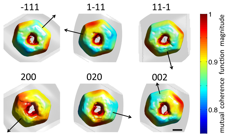
Partial coherence was accounted for following the approach of Clark et al. (Clark et al., 2012), using a 3D normalized mutual coherence function (MCF) to accommodate both longitudinal and transverse partial coherence. The MCF was updated every 10 iterations using 20 iterations of the Richardson-Lucy algorithm (Richardson, 1972). Fig. 4 shows a rendering of the crystal shape reconstructed from each of the six measured reflections, colored according to MCF magnitude at the crystal surface. Superimposed is a semi-transparent isosurface corresponding to a MCF magnitude of 0.75. For a fully coherent illumination the MCF would be unity everywhere. In the present case the MCF magnitude within the volume occupied by the crystal is always greater than 0.8.
Figure 4.
3D rendering of the crystal morphology recovered from each of the six measured reflections, coloured according to the magnitude of the normalized mutual coherence function at the crystal surface. Superimposed is a semi-transparent isosurface corresponding to a normalized mutual coherence function magnitude of 0.75. The black arrow indicates the direction of the scattering vector for each reflection. The scalebar corresponds to 300 nm.
Spatial resolution of the reconstructions was estimated by fitting the derivative of density line profiles across crystal-air-interfaces with a Gaussian. The Gaussian full width at half maximum and hence spatial resolution, averaged over six line profiles per reflection and over all reflections, is ~45 nm.
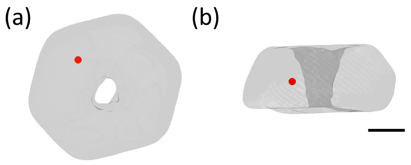
Phase ramps, which correspond to uniform lattice contraction or expansion and are not of interest here, were removed by re-centering the Fourier transform of the complex electron density. Reconstructions were transformed from the detector conjugated space, used for phase retrieval, to an orthogonal laboratory frame with x, y and z axes aligned as shown in Fig. 2 (b) and an isotropic real-space pixel spacing of 14.51 nm. Any phase wraps were unwrapped using the algorithm developed by Cusack et al. (Cusack & Papadakis, 2002), propagating outwards from the reference position shown in Fig. 5. This location was chosen as it is relatively far from the crystal-substrate interface, as well as the ion-damaged surfaces, and no steep phase gradients are expected. All reflections were set to have zero phase at this reference position.
Figure 5.
3D semi-transparent rendering of the recovered micro-crystal shape viewed from the top (a) and from the side (b). The superimposed red dot marks the position chosen as the phase origin for combining of phases recovered from all reconstructed reflections. The scalebar corresponds to 300 nm.
3. Results and Discussion
3.1. 3D lattice displacement field
To allow a direct comparison of the electron densities reconstructed from the CXDPs associated with different reflections, they must be transformed to the same coordinate frame. Here we use a reference frame defined by θ = χ = ϕ = 0°.
The orientation of the crystal when a specific hkl reflection is measured is captured by the rotation angles of the sample stack θhkl, χhkl and ϕhkl. This rotation can be expressed by a rotation matrix Rhkl:
| (6) |
By pre-multiplying the coordinates of the different hkl reflections by RhklT, all reconstructions can be rotated into the same reference coordinate frame.
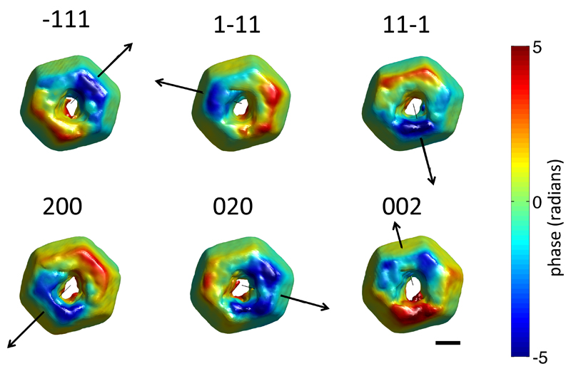
Fig. 6 shows the resulting plots of the electron densities recovered from the six crystal reflections, viewed from above, looking in the negative y-axis direction. The plotted shape is an electron density iso-surface marking the crystal-air interface. It is colored according to the phase, ψ̃hkl (r), recovered from each reflection. Superimposed are arrows indicating the direction of the scattering vector, qhkl, associated with each reflection.
Figure 6.
Rendering of the crystal morphology and phase variation, ψ̃hkl (r), recovered from the six measured reflections. The sample is shown in the same orientation for all six reflections. In each case an arrow indicating the direction of the scattering vector is superimposed. The scalebar corresponds to 300 nm.
The crystal morphologies recovered from each reflection are in remarkably close agreement. This is highlighted by Fig. 1 (c), where the morphologies determined from all crystal reflections have been rendered semi-transparent in different colors and superimposed. The average morphology of the crystal, taken as the mean of the recovered electron density magnitudes (Fig. 1 (d)), agrees very closely with an SEM micrograph of the sample (Fig. 1 (e)). The phase information in Fig. 6 is not straightforward to interpret and shows large variations in all reflections.
The phase ψhkl(r) of the complex electron density reconstructed from the CXDP of a particular reflection is given by ψhkl(r) = qhkl·u(r). Measured phases from at least 3 non-collinear reflections are required to reconstruct u(r). Here six non-collinear crystal reflections were measured and u(r) was recovered by minimising:
| (7) |
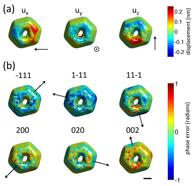
where ψ̃hkl (r) is the phase of the complex electron density recovered from experiments, and the sum was carried out over all measured hkl reflections. Fig. 7 (a) shows a rendering of the resulting components (ux(r), uy(r) and uz(r)) of the 3D displacement field in the crystal.
Figure 7.
Reconstructed displacement field in the sample and phase error associated with different reflections. (a) Rendering of the three components of the displacement vector, u(r), reconstructed within the sample. For each component an arrow indicating the direction of positive displacement is shown. (b) Rendering of the phase error, associated with all six reflections. An arrow indicating the direction of the scattering vector for each reflection is superimposed. The scalebar corresponds to 300 nm and applies to (a) and (b).
The availability of an over determined set of projections of the displacement field allows an assessment of the reliability of the recovered phases by computing a phase error term, :
| (8) |
Plots of computed for all six reflections, are shown in Fig. 7 (b). The mean phase error magnitudes, computed over the whole crystal, are 0.133 rad, 0.195 rad, 0.132 rad, 0.134 rad, 0.1181 rad and 0.1374 rad for the (-111), (1-11), (11-1), (200), (020) and (002) reflections respectively. These phase errors are significantly smaller than the measured phase variations. This consistency of the phases recovered from different reflections is remarkable, especially considering the complex structure and large distortions in this micro-crystal. It provides confidence that the phases in this micro-crystal were correctly reconstructed and that the large variations seen in Fig. 6 are indeed real.
3.2. 3D lattice strain and stress tensors
From the 3D lattice displacement field, u(r), the small strain tensor, ε(r), can be computed by differentiation (Constantinescu & Korsunsky, 2008):
| (9) |
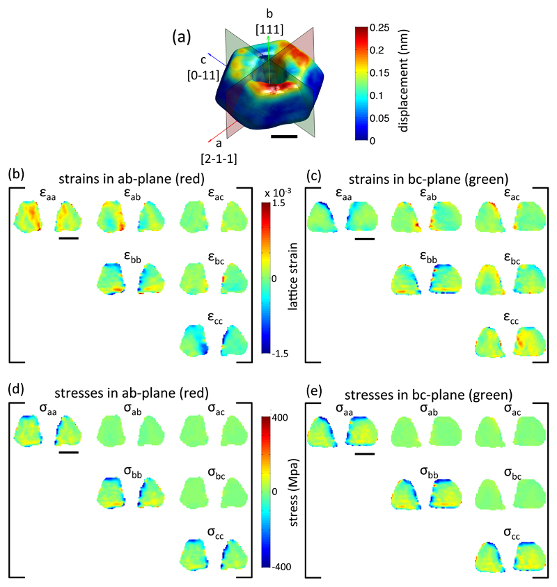
For convenience ε(r) values were transformed to an orthogonal sample space, a, b, c, where the a-axis is along the [2-1-1] direction, the b-axis along [111] and c-axis along [0-11], as shown in Fig. 8 (a).
Figure 8.
Reconstructed strains and stresses in the micro-crystal. (a) Rendering of the reconstructed lattice displacement magnitude |u(r)|. Superimposed are arrows indicating the directions of a, b and c axes and the corresponding crystallographic directions. Also shown are two sections (red and green) through the crystal for which strains and stresses are shown in (b, c) and (d, e) respectively. (b, c) six strain tensor components plotted on two sections through the crystal. (d, e) six stress tensor components plotted on two sections through the crystal. All scalebars correspond to 300 nm.
By definition ε(r) is symmetric and hence we choose a convention where plots of ε(r) show the upper triangle of the strain tensor. Fig. 8 (b, c) show the variation of all components of ε(r) plotted on two sections through the crystal. It is interesting to note that large strains are observed throughout the crystal and are not confined to the ion-milled top surface and the surface of the FIB-milled hole. This illustrates that the effects of FIB-milling extend far beyond the ion-damaged surface layer.
An interesting question concerns the uncertainty in the measured strains introduced by phase shift due to propagation in the crystal (Harder et al., 2007). For an optical path length l the phase change, ψ(r), is given by:
| (10) |
where δ is the real part of the complex refractive index, n, conventionally given by n = 1 – δ + iβ, and λ is the X-ray wavelength. At the X-ray energy used here δ = 2.87 x 10⁻⁵ (Henke et al., 1993). Thus propagation inside the crystals would lead to a phase gradient of radians per μm. This phase gradient is partly removed by re-centering the Fourier transform of the complex electron density as described above. To assess the strain error introduced by propagation in the gold crystals, we perform a worst-case analysis, considering a {111} reflection measured in back reflection. The strain error, Δε111 would then be:
| (11) |
This strain error due to propagation is significantly smaller than the strains due to ion implantation observed in this micro-crystal.
3D stresses, σ(r), in the micro-crystal were computed by rewriting ε(r) in Voigt notation and then pre-multiplying by the gold stiffness tensor, C (Dunne & Petrinic, 2005). For cubic materials the stiffness tensor has three unique non-zero components. Here we used gold literature values of c11=192.9 GPa, c44=41.5 GPa and c12=163.8 GPa (Hiki & Granato, 1966). It is important to note that to do this C must be rotated from coordinates attached to the crystal unit cell to the same coordinate frame as ε(r). The resulting components of σ(r), plotted on the same sections through the crystal as ε(r), are shown in Fig. 8 (d,e). Interestingly the ion-implantation damage causes stresses of several hundred MPa that far exceed the macroscopic yield strength of gold (Espinosa et al., 2004). The uncertainty in the measured stresses, introduced by the propagation effects described above, can be estimated as ±25 MPa. A more detailed analysis of the retrieved structure and the underlying defects is provided elsewhere (Hofmann et al., 2017).
4. Conclusion
In summary we have shown that, using micro-beam Laue diffraction, the lattice orientation of specific micro-crystals can be successfully determined. Using this information Bragg coherent diffraction imaging measurements of multiple reflections from the same micro-crystal can be reliably set up. In the present measurements, as well as more recent experiments, we were able to align six reflections within less than two hours. This capability opens the door to routine measurements of the full 3D lattice strain tensor within specific, arbitrarily-oriented micro-crystals.
We have illustrated this approach on a FIB milled gold micro-crystal, where we find large strains not only at the ion-damaged surfaces, but throughout the crystal. These results show that the effects of FIB machining extend far beyond the near surface defects it produces and advises caution in the use of FIB for the preparation of small-scale mechanical test samples.
Synopsis.
We present a new micro-beam Laue diffraction approach for the rapid, reliable alignment of multi-reflection Bragg coherent diffraction imaging measurements of arbitrarily oriented micro-crystals. This approach is used to map out the full, 3D-resolved lattice strain and stress tensors in a focussed ion beam machined micro-crystal.
Acknowledgements
The authors acknowledge Christian Beck for assistance with sample preparation. We also thank Jon Tischler and Edmund Tarleton for stimulating discussions.
Funding information John Fell Fund, University of Oxford (award No. 122/643); Royal Society (award No. RG130308); U.S. Department of Energy, Office of Science (award No. DE-AC02-06CH11357); Australian Research Council (award No. CE140100011); Engineering and Physical Sciences Research Council (award Nos. EP/H018921/1, EP/I022562/1); H2020 Euratom (award No. 633053); European Research Council (award No. 714697).
Footnotes
IMPORTANT: this document contains embedded data - to preserve data integrity, please ensure where possible that the IUCr Word tools (available from http://journals.iucr.org/services/docxtemplate/) are installed when editing this document.
References
- Beitra L, Watari M, Matsuura T, Shimamoto N, Harder R, Robinson I. AIP Conference Proceedings. 2010;1234:57–60. [Google Scholar]
- Busing WR, Levy HA. Acta Crystallogr. 1967;22:457–464. [Google Scholar]
- Chen C-C, Miao J, Wang CW, Lee TK. Phys Rev B. 2007;76:64113. [Google Scholar]
- Chung J-S, Ice GE. J Appl Phys. 1999;86:5249–5255. [Google Scholar]
- Clark JN, Beitra L, Xiong G, Higginbotham A, Fritz DM, Lemke HT, Zhu D, Chollet M, Williams GJ, Messerschmidt M, Abbey B, et al. Science (80-. ) 2013;341:56–59. doi: 10.1126/science.1236034. [DOI] [PubMed] [Google Scholar]
- Clark JN, Huang X, Harder R, Robinson IK. Nat Commun. 2012;3:993. doi: 10.1038/ncomms1994. [DOI] [PubMed] [Google Scholar]
- Clark JN, Ihli J, Schenk AS, Kim Y-Y, Kulak AN, Campbell JM, Nisbet G, Meldrum FC, Robinson IK. Nat Mater. 2015;14:780–784. doi: 10.1038/nmat4320. [DOI] [PMC free article] [PubMed] [Google Scholar]
- Constantinescu A, Korsunsky AM. Elasticity with Mathematica. Cambridge: Cambridge University Press; 2008. [Google Scholar]
- Coughlan HD, Darmanin C, Kirkwood HJ, Phillips NW, Hoxley D, Clark JN, Vine DJ, Hofmann F, Harder RJ, Maxey E, Abbey B. J Synchrotron Radiat. 2017;24:83–94. doi: 10.1107/S1600577516017525. [DOI] [PMC free article] [PubMed] [Google Scholar]
- Coughlan HD, Darmanin C, Phillips NW, Hofmann F, Clark JN, Harder RJ, Vine DJ, Abbey B. Struct Dyn. 2015;2 doi: 10.1063/1.4919641. [DOI] [PMC free article] [PubMed] [Google Scholar]
- Cusack R, Papadakis N. Neuroimage. 2002;16:754–764. doi: 10.1006/nimg.2002.1092. [DOI] [PubMed] [Google Scholar]
- Dunne F, Petrinic N. Introduction to computational plasticity. Oxford University Press; 2005. [Google Scholar]
- Espinosa HD, Prorok BC, Peng B. J Mech Phys Solids. 2004;52:667–689. [Google Scholar]
- Fienup JR. Appl Opt. 1982;21:2758–2769. doi: 10.1364/AO.21.002758. [DOI] [PubMed] [Google Scholar]
- Guizar-Sicairos M, Thurman ST, Fienup JR. Opt Lett. 2008;33:156–158. doi: 10.1364/ol.33.000156. [DOI] [PubMed] [Google Scholar]
- Harder R, Pfeifer MA, Williams GJ, Vartaniants IA, Robinson IK. Phys Rev B. 2007;76:115425. [Google Scholar]
- Henke BL, Gullikson EM, Davis JC. At Data Nucl Data Tables. 1993;54:181–342. [Google Scholar]
- Hiki Y, Granato AV. Phys Rev. 1966;144:411–419. [Google Scholar]
- Hofmann F, Abbey B, Liu W, Xu R, Usher BF, Balaur E, Liu Y. Nat Commun. 2013;4 doi: 10.1038/ncomms3774. [DOI] [PubMed] [Google Scholar]
- Hofmann F, Tarleton E, Harder RJ, Phillips NW, Ma P-W, Clark JN, Robinson IK, Abbey B, Liu W, Beck CE. Sci Rep. 2017;7:45993. doi: 10.1038/srep45993. [DOI] [PMC free article] [PubMed] [Google Scholar]
- Liu W, Ice GE, Assoufid L, Liu C, Shi B, Khachatryan R, Qian J, Zschack P, Tischler JZ, Choi J-Y. J Synchrotron Radiat. 2011;18:575–579. doi: 10.1107/S0909049511010995. [DOI] [PMC free article] [PubMed] [Google Scholar]
- Liu W, Ice G, Larson B, Yang W, Tischler J, Budai J. Metall Mater Trans A. 2004;35:1963–1967. [Google Scholar]
- Marchesini S, He H, Chapman HN, Hau-Riege SP, Noy A, Howells MR, Weierstall U, Spence JCH. Phys Rev B. 2003;68:140101. [Google Scholar]
- Newton MC, Leake SJ, Harder R, Robinson IK. Nat Mater. 2010;9:120–124. doi: 10.1038/nmat2607. [DOI] [PubMed] [Google Scholar]
- Pfeifer MA, Williams GJ, Vartanyants IA, Harder R, Robinson IK. Nature. 2006;442:63–66. doi: 10.1038/nature04867. [DOI] [PubMed] [Google Scholar]
- Richardson WH. J Opt Soc Am. 1972;62:55–59. [Google Scholar]
- Robinson I, Harder R. Nat Mater. 2009;8:291–298. doi: 10.1038/nmat2400. [DOI] [PubMed] [Google Scholar]
- Robinson IK, Vartanyants IA, Williams GJ, Pfeifer MA, Pitney JA. Phys Rev Lett. 2001;87:195505. doi: 10.1103/PhysRevLett.87.195505. [DOI] [PubMed] [Google Scholar]
- Ulvestad A, Clark JN, Harder R, Robinson IK, Shpyrko OG. Nano Lett. 2015;15:4066–4070. doi: 10.1021/acs.nanolett.5b01104. [DOI] [PubMed] [Google Scholar]
- Ulvestad A, Sasikumar K, Kim JW, Harder R, Maxey E, Clark JN, Narayanan B, Deshmukh SA, Ferrier N, Mulvaney P, Sankaranarayanan SKRS, et al. J Phys Chem Lett. 2016;7:3008–3013. doi: 10.1021/acs.jpclett.6b01038. [DOI] [PubMed] [Google Scholar]
- Ulvestad A, Singer A, Clark JN, Cho HM, Kim JW, Harder R, Maser J, Meng YS, Shpyrko OG. Science (80-. ) 2015;348:1344–1347. doi: 10.1126/science.aaa1313. [DOI] [PubMed] [Google Scholar]


