Abstract
Continuous-flow ventricular assist device (cfVAD) performance and patient hemodynamic conditions are intimately interrelated and dynamic, changing frequently with alterations in physiologic conditions, particularly pre- and afterloading conditions. The Heartware cfVAD (HVAD) provides a unique feature among currently approved VADs of providing an estimated instantaneous flow waveform, the characteristics of which can provide significant insights into patient and device properties. Despite being readily available, HVAD waveforms are poorly understood, underutilized, and insufficiently leveraged, even by clinicians who regularly manage HVAD patients. The purpose of this review is to provide the theoretical foundation for understanding the determinants of HVAD waveform characteristics and to provide practical examples illustrating how to interpret and integrate changes of HVAD waveforms into clinical practice. Heartware cfVAD waveforms should be considered a complimentary tool for the optimization of medical therapies and device speed in HVAD patients.
Keywords: HVAD, LVAD, waveforms, physiology, mechanical circulatory support
The treatment of patients with end-stage heart failure has been revolutionized by the advent of durable, continuous-flow ventricular assist devices (cfVADs).1–3 The inadequate availability of organs for transplantation coupled with increased durability and marked improvement in survival associated with cfVADs has led to a notable increase in the number of cfVADs implanted over the past 10 years and to an increasing number of patients alive on durable cfVAD support.2 Although there has been considerable improvement in survival associated with these devices, cfVAD-related complications remain a topic of increasing scrutiny especially because these have the potential to be reduced by improvements in patient management.1,3
Continuous-flow VAD performance and patient hemodynamic conditions are intimately interrelated and dynamic, changing frequently with alterations in physiologic conditions, particularly preload, afterload, and changes in intrinsic left ventricular (LV) function that occur during long-term support (i.e., reverse remodeling and myocardial recovery).4,5 The Heartware cfVAD (HVAD) has the unique feature among cfVADs currently approved in the United States of providing an estimated instantaneous flow waveform, the characteristics of which provide significant insights into patient and device properties. Yet, despite being readily available, HVAD waveforms are poorly understood, underutilized, and insufficiently leveraged, even by clinicians who regularly manage HVAD patients. The purpose of this review was to provide the theoretical foundation for understanding the determinants of HVAD waveform characteristics and to provide practical examples illustrating how to interpret and integrate HVAD waveforms into clinical practice. Commonly encountered clinical scenarios, nearly all of which were derived from actual patient cases, are provided. Some examples are derived from a previously validated cardiovascular simulation that incorporates HVAD pump characteristics.6,7 As these scenarios are reviewed, it is important to keep in mind that because details of the HVAD waveform vary among patients, changes of waveform characteristics from a patient’s baseline state are usually more informative and important than differences between patients. Given the wealth of available information, we postulate that changes in HVAD waveforms used in combination with other routinely available noninvasive clinical data have the potential to improve patient management and outcomes.
HQ Curves
The rate of blood flow (Q) through any cfVAD (be it an axial or a centrifugal flow pump) is dictated by the pressure gradient (H) between the inlet and outlet ports and the rotational speed (revolutions per minute [RPMs]) of its impeller.8,9 These relationships are depicted by “HQ curves”; HQ curves representative of the HVAD device are shown in Figure 1. At a given RPM, flow decreases as the pressure gradient increases. At a given pressure gradient, flow increases as the RPMs are increased. Because most cfVADs are implanted with the inflow cannula in the LV apex and the outflow graft anastomosed to the ascending aorta, the instantaneous pressure difference between the LV and the aorta is the main determinant of the pressure gradient (H) across the pump; this, in turn, determines the flow (Q) at that instant in time for a given pump speed. Accordingly, because both LV and aortic pressures vary during the cardiac cycle, so too does the pressure gradient across the pump (Figure 2A). This time-varying pressure gradient determines the characteristics of the flow waveform. During ventricular diastole, the pressure gradient between ventricle and aorta is large and pump flow is at its lowest value. Conversely, the pressure gradient is lowest during ventricular systole, and flow is at its highest value.
Figure 1.
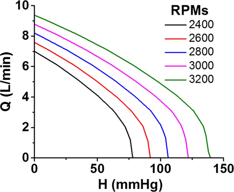
Pump flow (Q) is dependent on pressure gradient between the inflow cannula and outflow graft (H) and pump RPM. Increased RPMs results in increased flow at a given pressure gradient. RPM, revolutions per minute.
Figure 2.

A: Typical AOP and LVP tracings in a continuous flow ventricular assist device patient. At a fixed set speed, the pressure gradient between AOP and LVP during systole is relatively small and flow will be at its greatest value. Conversely, during ventricular diastole, the pressure gradient is relatively large and flow will be at its lowest value. B: A typical HVAD waveform of three consecutive beats. The peak of each waveform represents maximum instantaneous flow, the trough represents the minimum instantaneous flow, and the difference between peak and trough is referred to as the pulsatility. The mean flow, which is displayed on the patient monitor, is the average waveform during a beat. The time interval between waveform peaks reflects the heart rate; because the HVAD monitor displays 10 seconds of data, heart rate can be calculated by counting the number of waveforms displayed on the monitor and multiplying it by six. AOP, aortic pressure; HVAD, Heartware continuous-flow ventricular assist device; LVP, left ventricular pressure.
As noted above, with increasing RPMs, the HQ curve shifts upward so that the pump will deliver more flow at a given pressure gradient. However, a critical concept, to be emphasized further below, is that an increase in pump speed does not always result in an increased pump flow; rather, the simultaneous impact of pump speed changes on aortic and ventricular pressures (governed by the relatively complex nature of device–patient interactions) determines the impact of RPM changes on flow.4,5,10 Other determinants of pump flow include the pressure gradients across the inflow cannula and outflow graft and the inertia of blood.8 Although not normally considered important, these factors can become significant under certain conditions, such as when the inflow cannula or outflow graft is obstructed (e.g., constricted graft-aorta anastomosis), compressed, or clotted.
Nomenclature and the Normal HVAD Waveform
As detailed above, the HVAD waveform reflects the instantaneous flow through the pump at any point in time (Figure 2B). Because flow varies throughout the cardiac cycle, the waveform can be characterized by a peak, a trough, and a pulsatility, the latter defined by the difference between peak and trough. Additionally, because each waveform cycle is indicative of flow during one heartbeat, the time interval between waveform peaks directly reflects the heart rate. The value for flow displayed on the patient monitor is a running average of the flow waveform, thus reflecting the mean pump flow. Other features, such as the rate of rise of flow during diastole and systole, have been shown to correlate with factors such as LV end-diastolic pressure and LV dP/dtmax11; changes in waveform morphology have also been used to detect the presence of aortic valve opening.12
Before proceeding with descriptions of how waveforms change in various clinical scenarios, there are two noteworthy technical points related to the estimation of HVAD flow. First, as detailed previously,13 flow estimation is based on the fact that the electrical current drawn by the pump depends on pump rotational speed, the viscosity of blood, and the rate of blood flow through the pump. Electrical current is measured directly by the controller and by the monitor. Viscosity of blood is determined by hematocrit; accurate flow estimation is therefore dependent on hematocrit being properly set in the monitor. Flow is then determined simply by applying the experimentally determined interrelationships between current, RPMs, and viscosity. Second, in the presence of thrombus formation within the pump, there are dramatic increases of electrical power resulting in significant overestimations of flow. The characteristics of the waveform in the presence of thrombus have been discussed in detail previously14 and will be discussed herein.
Clinical Scenarios
As emphasized above, the waveform characteristics are determined by the interaction between the patient and the HVAD. Accordingly, changes in waveform characteristics reflect changes in patient status or pump function. Below, we review commonly encountered clinical scenarios that, when recognized during routine clinical care, have the potential to avert certain types of adverse events and can help with the differential diagnosis when in the midst of an event or a change in clinical status.
Changes in Volume Status (Hypervolemia and Hypovolemia)
Fluctuations of volume status are common in cfVAD patients. In the early postoperative state, fluid balance can vacillate frequently in association with blood loss, transfusions, diuretics, and intravenous drug and fluid infusions. In the ambulatory setting, as patients’ ventricular function and heart failure syndrome improves or worsens on cfVAD support, diuretic requirements may increase, lessen, or even require discontinuation. Such changes in volume status can impact ventricular filling pressures and pressure generation, which are reflected in the HVAD waveform.
In states of hypervolemia (Figure 3A), increased LV filling results in higher diastolic and systolic LV pressures that decrease the pressure gradient across the pump and result in higher pump flows, especially during systole. This can also increase pulsatility. More subtle, a steep upward slope of the waveform during diastole may be appreciated because of the rapid rise of LV pressure during ventricular filling.11 Conversely, in a hypovolemic state (Figure 3B), ventricular systolic and diastolic pressures are reduced, pressure gradient across the pump is increased, and peak flow, mean flow, and pulsatility decrease. Waveform slope during diastole also decreases.
Figure 3.
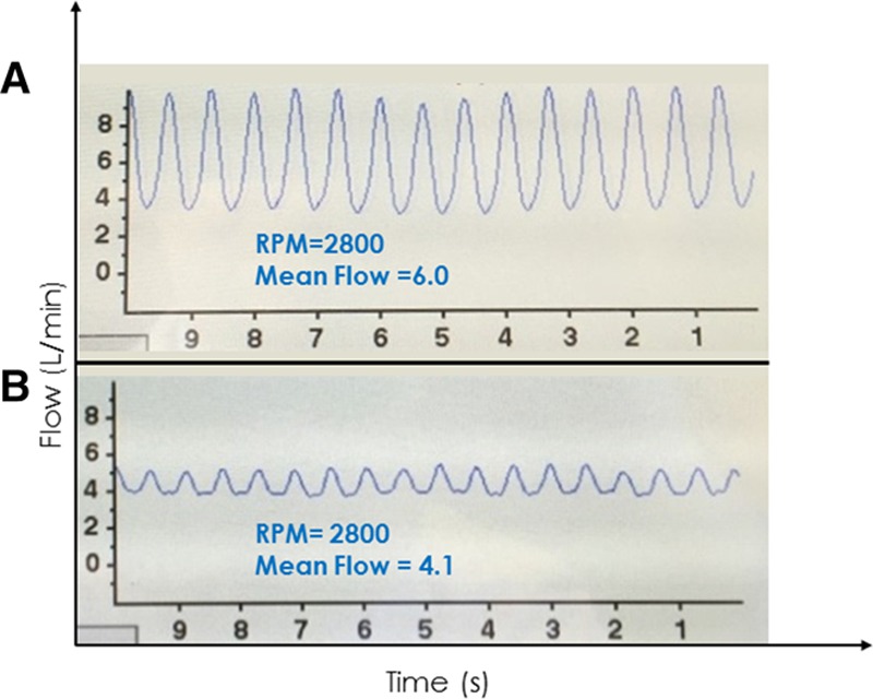
A: Waveform from a 62 year old man 4 weeks post HVAD implant. The patient had evidence of volume overload on examination and the waveform showed high flow (mean value 6.0 L/min) with high pulsatility (approximately 6 L/min). B: Waveform from a 56 year old man 6 weeks post HVAD implant who presented to clinic for routine follow-up. He reported feeling well but had a complaint of occasional, intermittent dizziness. His waveform showed relatively low flow (mean 4.1 L/min) and low pulsatility (~1 L/min) indicative of a relative hypovolemic state. Provocative maneuvers including positional changes induced intermittent suction with standing and a marked increase in flow and waveform pulsatility with supine positioning. As a result of the history, waveform and waveform changes, HVAD speed was reduced by 100 RPM, and diuretics were discontinued. HVAD, Heartware continuous-flow ventricular assist device; RPM, revolutions per minute.
In the clinical setting, detection of waveform changes in real time can be leveraged using interventions such as a passive leg raise maneuver or an infusion of intravenous fluids to increase preload or having the patient move from a supine to upright position to reduce preload. The waveform depicted in Figure 4A was from a patient who returned to clinic with a complaint of intermittent lightheadedness. The waveform is of low peak flow, low mean flow, and low pulsatility, all suggestive of a low volume status. The waveform depicted in Figure 4B shows the same patient minutes into a passive leg raise to 45°, which shifts blood from periphery to the central circulation, increasing LV filling and pressure generation. This restores waveform flow pulsatility, peak and mean values.
Figure 4.
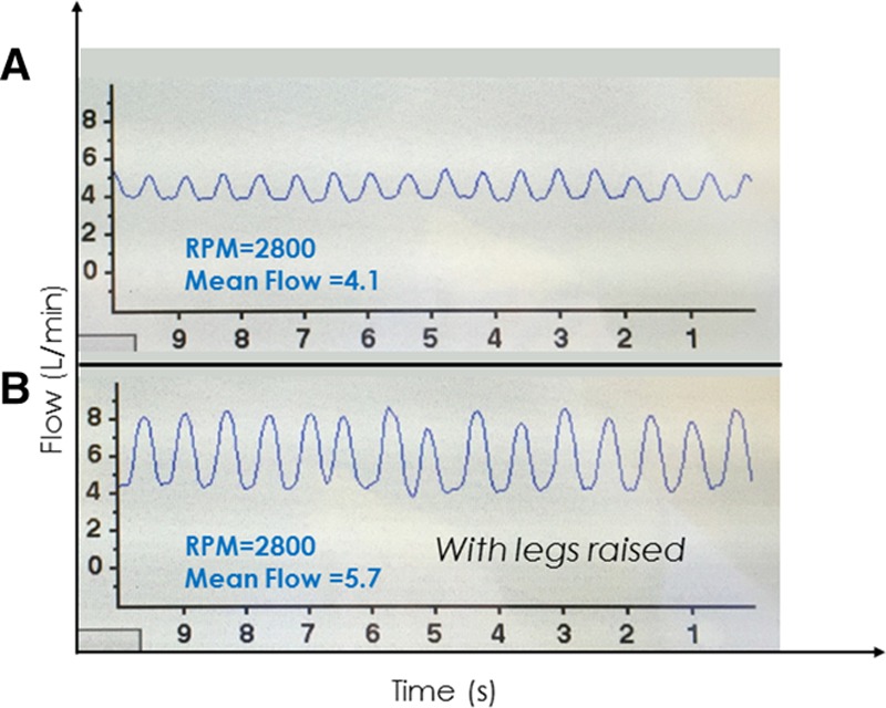
A: Clinical hypovolemia associated with a low-flow, low-pulsatility waveform with patient sitting upright and legs dangling. B: Both flow and pulsatility increased within minutes after a passive leg raise maneuver.
Changes in Afterload (Hypertension and Hypotension)
Changes in systemic vascular resistance are commonly encountered in cfVAD patients, which can result in either hypertension or hypotension. In the case of hypertension (Figure 5A), the increase in arterial pressure can markedly increase the LV-aortic pressure gradient, particularly during diastole. As a result, although peak flow may be only minimally decreased, mean and trough flows are markedly decreased with resulting marked increases in pulsatility. In some cases, the high diastolic pressure gradient can cause flow to approach 0 L/min (as in Figure 5A) or even attain negative values in extreme cases. This can be appreciated from the HQ curves; note that at a speed of 2400 RPM, flow is 0 L/min at a pressure gradient of 100 mm Hg (Figure 1). In such circumstances, it is important to resist the temptation to increase VAD speed in response to the drop in mean flow, because this may lead to nominal increases in flow with possible worsening of the hypertension. The more appropriate response is to evaluate and medically manage volume status and afterload resistance. This is of particular relevance given the known association between poorly controlled blood pressure and risk of stroke.15,16 Given the challenges of measuring (and interpreting) blood pressure in cfVAD patients,17 the presence of a “hypertensive waveform” can sometimes serve as a useful arbiter when Doppler blood pressure measurements are equivocal.
Figure 5.
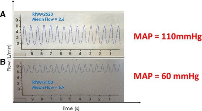
A: A 65 year old man with an ischemic cardiomyopathy, 6 months post HVAD implant presents to clinic for a follow-up visit. A low-flow, high-pulsatility waveform with a low-flow trough was seen on the HVAD monitor suggestive of relative hypertension. Systolic pressure by Doppler was 110 mm Hg. B: A 44 year old man 2 month post HVAD implant developed bacteremia related to a driveline infection. A high-flow, low-pulsatility waveform was seen on the HVAD monitor suggestive of relative hypotension due to excessive vasodilatation. Systolic blood pressure by Doppler was 60 mm Hg. HVAD, Heartware continuous-flow ventricular assist device.
Conversely, during states of low afterload resistance and relative hypotension (e.g., vasoplegia, excessive vasodilator therapy), an increase in mean HVAD flow is observed because of the lower LV-aortic pressure gradient throughout the cardiac cycle (Figure 5B). As shown in this example, peak and trough flows are both greater than normal, and there is a resulting decrease in pulsatility. As with hypertension, the low afterload state exerts a more significant influence during diastole than in systole. The result will be a high-flow, low-pulsatility waveform.
Right Heart Failure
Right heart failure (RHF) is relatively common in cfVAD patients, occurring at a rate of ~0.3 events/patient·year.1 Right heart failure can occur early after VAD implantation (even at the time of implant, before leaving the operating room) or can occur late, after many months of cfVAD support.1,18,19 Although early RHF may be associated with elevations in pulmonary artery pressures and pulmonary vascular resistance, late RHF is more often caused by RV volume overload and decreased contractility and is associated with more normal PA pressures. Regardless of timing or cause, when severe enough, RV cardiac output is reduced, resulting in LV underfilling and low pulmonary capillary wedge pressure (PCWP). In this regard, and for the same reasons, the HVAD waveform associated with RHF generally mimics that of a severe hypovolemic state with decreased peak flow, mean flow, and flow pulsatility (Figure 6A). The differentiation of RHF from hypovolemia relies on the detection of clinical signs such as jugular venous distention, peripheral edema, echocardiographic evaluation, and, when needed, invasive measurement of central venous pressure, PCWP, and cardiac output. Establishment of a specific diagnosis is important because management of RHF differs significantly from that of hypovolemia, typically relying on diuretics, inotropic agents, and adjustments (sometimes lowering) of pump speed. Similar to hypovolemia, effective treatment of RHF can be reflected in the HVAD waveform and associated with an increase in VAD flow and pulsatility. This is illustrated in the waveform shown in Figure 6B, which was obtained from the same patient as in Figure 6A after treatment with intravenous milrinone. Improved RV contractility improves LV filling and pressure generation, which restores the waveform to normal.
Figure 6.
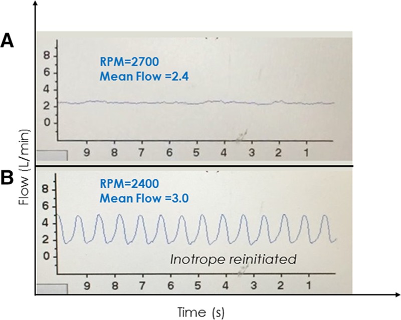
A: A 58 year old woman postoperative day 7 post Heartware continuous-flow ventricular assist device implant. Inotropes were stopped and several hours later, she developed a low-flow alarm with this low-flow, low-pulsatility waveform suggestive of a low left ventricular filling state; the proximity in time to discontinuation of inotropes suggested the possibility of right heart failure. Intermittent suction events were also occurring (not shown), which resolved upon lowering the speed from 2700 to 2400 RPM. B: After reinitiating inotropes for right heart failure, flow and pulsatility increased. RPM, revolutions per minute.
Aortic Regurgitation
Aortic regurgitation (AR) is a well-described complication of long-term cfVAD support.20,21 Its onset is often gradual but once of sufficient severity, significant and deleterious clinical consequences may ensue. These are generally manifest as an inability to unload the LV with emergence of symptoms of left and RHF. The HVAD waveform in the presence of AR is characterized by high peak, mean, and trough flows and low pulsatility (Figure 7). The severely regurgitant lesion serves to equalize pressure between the aorta and LV more than normal, minimizing the pressure gradient and increasing pump flow. During diastole, the regurgitant flow can markedly increase LV diastolic pressure, again reducing pressure gradient and increasing pump flow. These effects underlie the decrease in pulsatility. In the absence of other valvular pathology, the decreased aortic pressure and equalization of aortic and LV pressures would typically result in aortic valve opening on every beat. However, the underlying pathology that results in AR relates to fusion and distortion of the aortic valve cusps that reduces coaptation. Thus, in typical cases, the aortic valve does not open.21 Finally, and importantly, AR presents a unique situation in which flow through the pump does not reflect flow to the body because a large part of the flow recirculates through the LV and pump without reaching the periphery. When AR becomes severe, medical interventions (e.g., afterload reduction) are typically ineffective and aortic valve replacement should be considered. In addition to utilizing imaging modalities to evaluate AR severity, a high PCWP that does not decrease with increases in VAD speed further supports the clinical suspicion of clinically important AR. Although perhaps counterintuitive, decreasing the pump speed, which will reduce the amount of regurgitant flow, is also likely to reduce net forward flow and is thus usually not effective in resolving hemodynamic or clinical consequences. On the other hand, speed increase in this setting can lower PCWP and increase forward cardiac output.21
Figure 7.
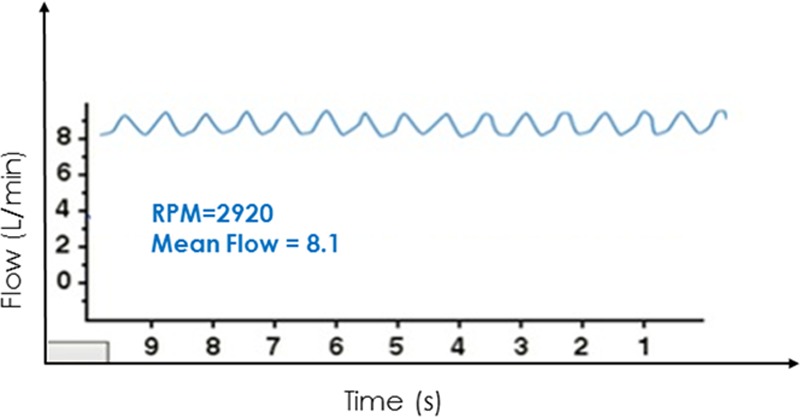
This high-flow, low-pulsatility waveform derived from a cardiovascular simulation6,7 is representative of what is seen in cases of severe aortic regurgitation.
Cardiac Tamponade
Cardiac tamponade most often occurs during the postoperative period (days to weeks) after cfVAD implantation. When fluid accumulates in the pericardial space, the resulting increase in pericardial pressure restricts filling of both ventricles. In consequence, there are relatively small increases in LV diastolic pressures and marked reductions in systolic pressure. The latter increases the pressure gradient across the pump, thus decreasing peak flow, mean flow, and pulsatility (Figure 8). In addition to these quantitative changes, the waveform itself loses its typical nearly sinusoidal appearance tending to exhibit periods of constant flow between systolic periods. This is due to the loss of the normal rapid drop and gradual rise of LV pressure during diastole; rather, in this condition, LV pressure drops rapidly to and remains nearly constant at the pericardial pressure throughout the filling phase of the cardiac cycle resulting in a nearly constant pressure gradient across and flow through the pump.
Figure 8.
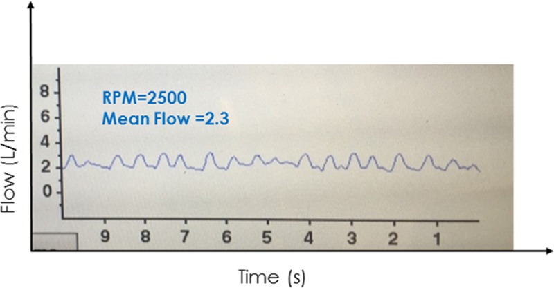
A 62 year old man 2 days post HVAD implant showed an abrupt drop in VAD flows and flow pulsatility, followed by a gradual drop in blood pressure and urine output. Waveforms had relatively long intervals of constant flow between peaks. Echocardiography confirmed a large pericardial effusion with biventricular collapse. A pericardial window was performed with immediate improvement in hemodynamics and restoration of a normal HVAD waveform. HVAD, Heartware continuous-flow ventricular assist device.
Although hypotension and clinical signs of low cardiac output may eventually ensue, the described changes in the waveform will often precede clinical findings because mean HVAD flow can generally be maintained near normal values until ventricular filling is severely limited. However, consideration of a broad differential diagnosis is needed as other common scenarios occurring in the early postoperative state (blood loss and RHF) may result in a similar low-flow, low-pulsatility waveform. Relief of the tamponade via pericardiocentesis or a pericardial window will rapidly restore a more normal appearing waveform with increased flow and pulsatility.
Changes in Left Ventricular Contractility and Pump Revolutions Per Minute
Although native LV systolic function is uniformly severely impaired in patients implanted with a cfVAD, changes in LV function (improvements due to recovery or decrements due to progression of the underlying heart failure state) can impact overall device performance and the HVAD waveform. More generally, as discussed above, the overall hemodynamic state of a cfVAD-supported patient depends on the relative strengths of the two pumps (LV and cfVAD) working in parallel. The contractility of the LV is indexed by parameters such as ejection fraction or the more appropriate, load-independent end-systolic elastance (Ees).22 By analogy, the effective “contractility” of a cfVAD with a given set of HQ curves is indexed by its rotational speed (i.e., rotor RPMs). As it relates to the HVAD waveform, a decrease in LV contractility (Ees) at a given HVAD RPM reduces LV systolic pressure generation and tends to increase end-diastolic pressure. These increase the pressure gradient across the pump during systole and tend to reduce the pressure gradient during diastole, which translate to a significant decrease in peak and mean flows, some increase of diastolic flow, and a substantial decrease in pulsatility (Figure 9A). Conversely, at a given HVAD RPM, an increase in LV contractility increases LV systolic pressure generation, resulting in more consistent aortic valve opening, and tends to decrease end-diastolic pressure. These decrease pressure gradient across the pump during systole and tend to increase the pressure gradient during diastole, which translate to a significant increase in peak and mean flows, some decrease in diastolic flow, and a substantial increase in pulsatility (Figure 9A).
Figure 9.
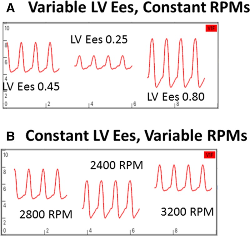
A: Changes in waveforms with changes in LV contractility at a constant RPM. A decrease in contractility results in a decrease in waveform peak and mean values, an increase in trough, and a decrease in pulsatility. The opposite occurs with an increase in contractility. B: Changes in waveform with changes in RPMs from a baseline value of 2800 RPMs with constant LV contractility. With RPMs decreased to 2400, peak, trough, and mean flows decreased and pulsatility increased. The opposite occurs when RPMs are increased to 3200. Waveforms derived from a cardiovascular simulation (6,7). LV, left ventricle; RPM, revolutions per minute.
The effects of varying RPMs at a given LV contractility (Figure 9B) are more complicated to explain because effects of changes in pressure gradients must be combined with the effects of shifting between RPM-dependent HQ curves.8,9 When RPMs are decreased, the degree of LV unloading decreases so that both end-diastolic and peak systolic LV pressures increase; these would act to increase peak, trough, and mean flows; however, the reduced RPMs act to decrease the flow at any given pressure gradient. The net effects are decreases in peak, trough, and mean flows with a marked increase in pulsatility. Conversely, although an increase in RPMs enhances LV unloading resulting in increased pressure gradients during diastole and systole, the increase in RPM dominates the effect so that peak, trough, and mean flows increase with a decrease in pulsatility.
Arrhythmias
Atrial fibrillation.
Atrial fibrillation is common in heart failure and in cfVAD patients. The usual physical examination findings consisting of an irregularly irregular peripheral pulse and discordance between peripheral pulses and precordial auscultatory heart sounds are usually obscured in the presence of a cfVAD. However, the HVAD monitor provides an immediate indication of the presence of atrial fibrillation consisting of irregularly timed waveforms (Figure 10). The irregularity is evident in both the varying intervals between cardiac cycles and in the beat-to-beat variations in waveform pulsatility. The latter is due to the varying time intervals between beats, which influence both ventricular filling and LV contractility. Accordingly, beats preceded by longer time intervals are associated with increased pulsatility. Occasionally, a waveform suggestive of atrial fibrillation may be confused by the presence of frequent, multifocal premature ventricular contractions (PVCs, discussed below). Thus confirmation of the diagnosis should be made using an electrocardiogram (ECG).
Figure 10.
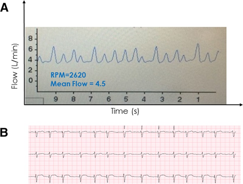
A 64 year old woman ~1 year post HVAD implant found during a routine office visit to have irregularly timed HVAD waveforms with varying peak flows (with high flows occurring after longer intervals) suggestive of atrial fibrillation, which was confirmed by electrocardiography. HVAD, Heartware continuous-flow ventricular assist device.
Premature ventricular contractions.
The presence of PVCs is also reflected in the HVAD waveform. The waveform(s) preceding the PVC will have a normal appearance (Figure 11A). The waveform associated with the PVC itself, however, will often be one with markedly lower pulsatility due to reduced ventricular filling time and reduced contractility (red arrow).23 The post-PVC waveform (green arrow) typically demonstrates properties of the classic phenomenon of postextrasystolic potentiation24 after a compensatory pause, on which there is both increased ventricular filling and increased contractility; these are reflected by an increase in pulsatility. The example of Figure 11, B and C shows the waveform of patient with a bigeminal rhythm, with alternating strong beats preceded by the longer time interval (red arrows) and weak beats preceded by the short intervals (green arrows). When frequent ventricular ectopy is present, an ECG may be required to discern the underlying ectopy from arrhythmias such as atrial fibrillation.
Figure 11.
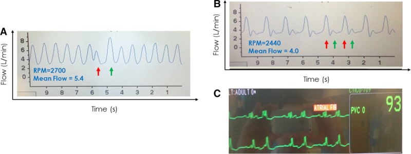
A: A premature ventricular contraction occurred (ECG not shown) resulting in a premature contraction with waveform of lower peak flow and reduced pulsatility (red arrow) followed by a compensatory pause and postextrasystolic potentiation reflected in the waveform with higher peak flow and greater pulsatility (green arrow). The remainder of the waveform is otherwise normal. B: A waveform showing a “bigeminy” pattern (alternating red and green arrows) consistent with the patient’s underlying sinus rhythm with ventricular bigeminy noted on ECG (C). ECG, electrocardiogram.
Tachycardias.
Accurate measurement of heart rate in a cfVAD patient is challenging by physical examination. Additionally, tolerability of arrhythmias, including ventricular tachycardia (VT), supraventricular tachycardias (SVTs), and even ventricular fibrillation (VF) in cfVAD-supported patients is variable, in part determined by underlying RV function, the presence and degree of residual pulmonary hypertension, and the rate of the arrhythmia. Some patients will remain asymptomatic despite sustained runs of tachycardias because of the support provided by the cfVAD.
However, leveraging the fact that the time interval between individual waveform peaks is directly related to heart rate and the presence of a fixed 10 second time axis on the HVAD patient monitor makes measuring patient heart rate straightforward by simply counting the number of waveforms on the display monitor and multiplying by six. Accordingly, the HVAD monitor can also be used to detect the presence of potentially dangerous tachycardic rhythms (Figure 12).
Figure 12.
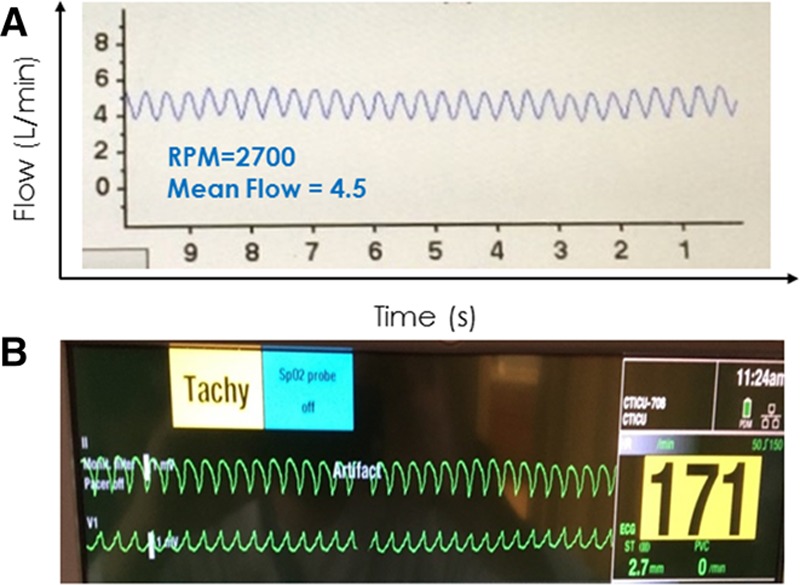
A 27 year old man post HVAD implant presented for a routine office visit. The HVAD waveform (A) showed normal flow, low pulsatility, and a heart rate of ~170 bpm (number of waveforms on the monitor × 6). He denied any symptoms. An ECG (B) confirmed sustained ventricular tachycardia at 170 bpm. HVAD, Heartware continuous-flow ventricular assist device.
Because diastolic filling time is reduced during VT, this will often translate to a relatively low-flow, low-pulsatility waveform. Although flow will decrease throughout the cardiac cycle, a net decrease in pulsatility occurs because of the disproportionate decrease in flow during systole when the LV has less pressure generation. Without routinely ordering an ECG, rapid ventricular arrhythmias may go undetected on physical examination but would not be missed via inspection of the waveform. In contrast to an SVT or VT, the waveform in VF would exhibit complete loss of pulsatility because of the absence of LV pressure pulses. Because the RV is also affected by VF, the LV is underfilled resulting in a relatively large pressure gradient across the pump and low mean flow.
Intra-Aortic Balloon Pump
Patients with end-stage heart failure, particularly when presenting with cardiogenic shock, are often supported by an acute, temporary support device as a bridge to a durable cfVAD. Although many such devices will be removed at the time of cfVAD implant, one exception is the intra-aortic balloon pump (IABP), which may not be removed until hours or days afterward. The presence of a functioning IABP (i.e., not in standby mode) will impact the HVAD flow waveform in a predictable manner; the availability of data with different LV contraction-to-balloon inflation ratios (1:1, 1:2 and 1:3) is particularly instructive (Figure 13). Intra-aortic balloon pumps operate via counterpulsation, inflating at the onset of diastole and deflating at the onset of systole. During unsupported beats, a typical flow and pulsatility profile reflective of the patient’s underlying cfVAD-supported physiology will be observed in the waveform. In the example of Figure 13A obtained in a patient early after surgery during IABP standby mode, a low-pulsatility, low-flow pressure tracing is seen consistent with the patient’s state of low LV contractility. During IABP supported beats with a 1:3 pumping ratio (Figure 13B, left), two normal beats are seen (red bars). This is followed by an IABP-supported beat on which the diastolic balloon inflation increases aortic pressure, increases pressure gradient across the pump, and markedly decreasing diastolic flow (green bar). During the ensuing systole, the balloon deflates, reducing pressure gradient across the pump and increasing peak flow on that beat relative to the preceding unsupported beats. Thus, a marked increase in pulsatility is observed in the HVAD waveform during each cardiac cycle in which the IABP is triggered. The corresponding balloon inflation pressures in relation to the ECG are illustrated in the panel on the right of the figure. At 1:2 pumping ratio, we see the same effects on every other beat (Figure 13C). The impact of IABP on cfVAD flow has been reported for another cfVAD.25 Finally, at a 1:1 pumping ratio (Figure 13D), a high-pulsatility tracing is observed. As also indicated in the figure insets, in this particular case, the IABP increased the net flow from 4.0 L/min during standby mode to 4.6 L/min with a 1:1 pumping ratio, which was mainly a result of increased peak flows during systole that overcompensated for the marked decrease in flow during diastole; IABP had a marked hemodynamic impact during deflation, decreasing blood pressure from 88 to 59 mm Hg (see arterial pressure recorded on the right panels). However, such dramatic effects may not be typical; anecdotal experience, at least one case report,25 and results of cardiovascular modeling6,7 suggest that IABP may have a small negative impact on VAD flows although total cardiac output may remain unchanged.
Figure 13.
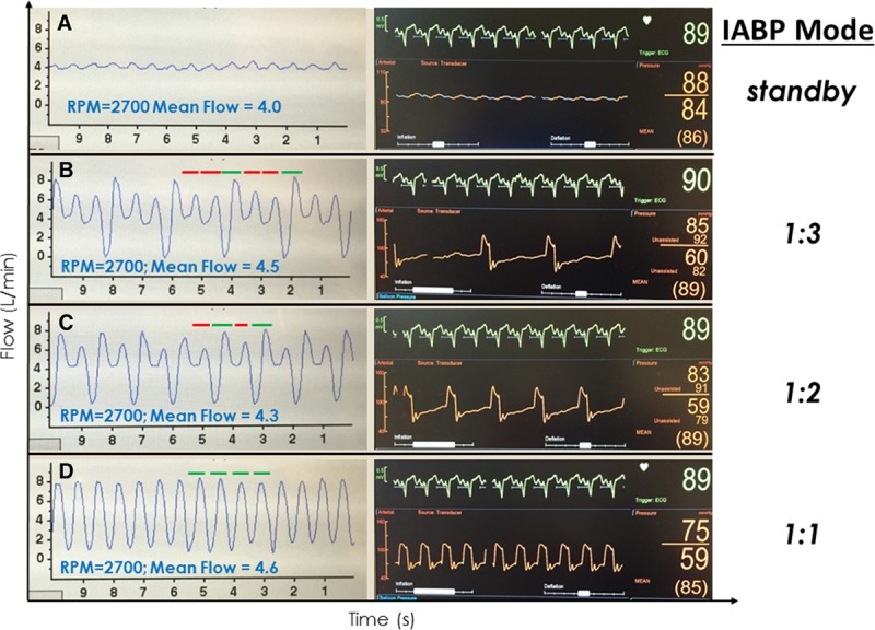
HVAD waveforms and corresponding arterial pressure tracings in an IABP-supported patient immediately after an HVAD implant during standby (A), 1:3 (B), 1:2 (C), and 1:1 IABP (D) trigger modes, respectively. Red bars reflect flow during “unsupported” IABP beats and green bars reflect flow during “supported” beats. HVAD, Heartware continuous-flow ventricular assist device; IABP, intra-aortic balloon pump.
Suction Events
Continuous-flow devices are subject to suction, either because of suboptimal inflow cannula position or under conditions that result in significant left ventricular underfilling. The latter may occur in a variety of clinical conditions such as hypovolemia, RV failure, or cardiac tamponade. Additionally, ventricular arrhythmias may cause suction events; conversely, suction events may precipitate ventricular arrhythmias caused by mechanical irritation of the myocardium.
One of the most useful and easily recognizable features of the HVAD waveform is identification of suction events. Such events may be either intermittent and self-clearing, or continuous in nature. The image of Figure 14A shows a low-flow, low-pulsatility HVAD waveform, typical of a patient with low LV filling. In the same patient, intermittent suction was induced by positional changes (Figure 14B). The flow waveform is characterized by intermittent, relatively sharp downward deflections toward 0 L/min during systole; recall that flow normally increases during systole. The cfVADs are most susceptible to suction events during systole because of ventricular contractions bringing the inflow cannula in closer proximity to the septum or free wall. During diastole, when the LV fills and volume increases, suction events can clear (either permanently or until the following ventricular systole) and flow increases. During continuous suction (as shown in Figure 14C), the diagnosis may not be readily apparent because the lack of an ECG on the HVAD monitor limits ability to discriminate systole from diastole. However, close inspection reveals that the downward deflection of the waveform occupies approximately 1/3 of the cardiac cycle (systole), whereas the higher flow occupies approximately 2/3 of the cardiac cycle (diastole), which should assist in securing the diagnosis.
Figure 14.
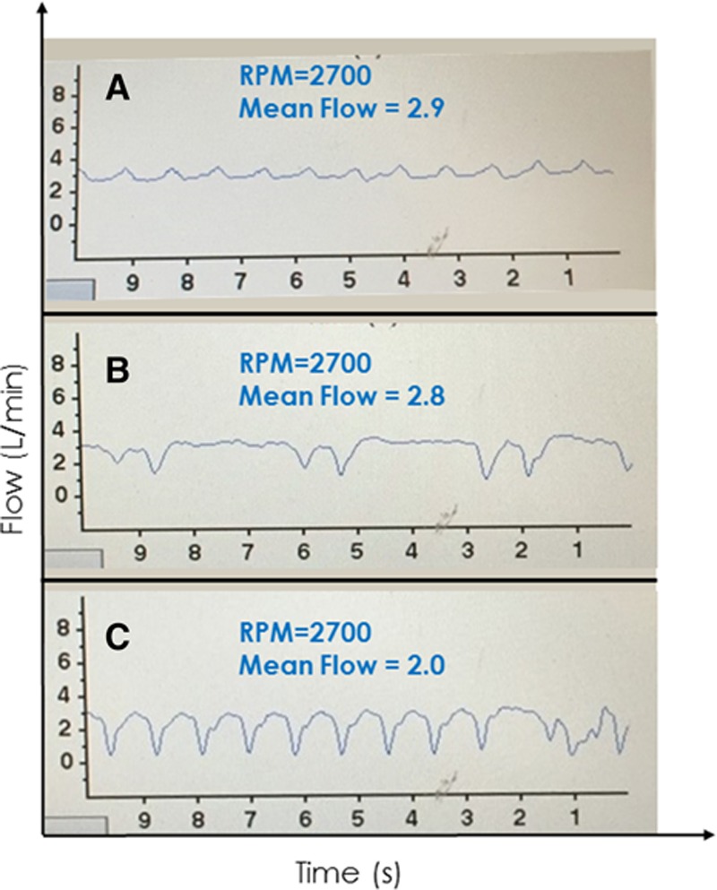
A low-flow, low-pulsatility waveform in an Heartware continuous-flow ventricular assist device-supported patient in a supine position with suspected hypovolemia (A). Changing position to sitting (B) induced intermittent suction followed by continuous suction when the patient stood up (C).
Pump Thrombus
As noted above, HVAD flow is overestimated in the setting of pump thrombus, because more energy is required to maintain rotor speed.14 As detailed previously, it is usually more helpful in this setting to look at the HVAD log file, which provides a long-term history of power consumption and estimated flow. As detailed by Jorde et al.14 (Figure 15), pump thrombosis can build gradually (Figure 15A), occur suddenly (Figure 15B), or be the result of thrombus ingestion (Figure 15C). Although the waveform of severe AR may resemble that seen with pump thrombosis, echocardiography will usually readily exclude this from the differential diagnosis. Also, pump thrombosis is easily differentiated from inflow or outflow obstruction because power consumption decreases in those cases and the waveform takes on a characteristic appearance (Figure 15D).
Figure 15.
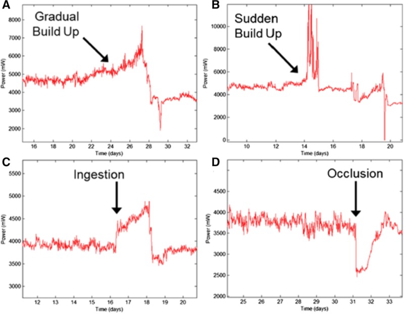
These Heartware continuous-flow ventricular assist device log file tracings from Jorde et al.14 show examples of how power consumption changes over time with different time courses of pump thrombus formation (A, B, and C) and with an occlusion of the inflow cannula or outflow graft. See reference 14 for details. Reproduced with permission from Elsevier.
Summary and Conclusions
Heartware cfVAD waveform characteristics reflect the complex interaction between the cfVAD and the patients’ dynamic, physiologic conditions. Along with echocardiography, the HVAD waveforms are emerging as an indispensable tool in both the evaluation and optimal management of HVAD-supported patients. We emphasize that because there is significant variability in the normal waveform among patients, it is most useful to evaluate changes from each patient’s own normal pattern. Furthermore, the HVAD waveform should not to be interpreted in isolation but should be considered in its clinical context. In this regard, the nature of changes in a patient’s HVAD waveform can be used to generate a differential diagnosis as summarized in Table 1. Changes in waveform morphology in response to acute maneuvers such as postural changes, volume infusions, and inotropic stimulation can help narrow the differential diagnosis. The differential diagnosis can also help guide the decision of which, if any, additional testing (such as ECGs, blood tests, right heart catheterization) is required to arrive at final diagnosis.
Table 1.
Differential Diagnosis Based on HVAD Flow Waveform Characteristics

In summary, waveforms should be considered a complimentary tool in the care of the VAD patient, integrated with other clinical information into the daily management of these patients, both in the office and in the hospital setting. As we have learned from trials of indwelling pulmonary artery catheters,26 we must be mindful that we evaluate and treat the patient, not a set of numbers (or waveforms). However, through a better understanding of how waveforms are generated and why they change as illustrated in commonly encountered clinical scenarios above, improved diagnostics and delivery of care to cfVAD-supported patients can be achieved.
Footnotes
Disclosures: J.D.R. has served as a consultant for Heartware (currently Medtronic) and Thoratec (currently Abbott). D.B. was previously an employee by Heartware and is currently a consultant to Medtronic.
References
- 1.Aaronson KD, Slaughter MS, Miller LW, et al. ; HeartWare Ventricular Assist Device (HVAD) Bridge to Transplant ADVANCE Trial Investigators: Use of an intrapericardial, continuous-flow, centrifugal pump in patients awaiting heart transplantation. Circulation 2012125: 3191–3200.. [DOI] [PubMed] [Google Scholar]
- 2.Kirklin JK, Naftel DC, Pagani FD, et al. Seventh INTERMACS annual report: 15,000 patients and counting. J Heart Lung Transplant 201534: 1495–1504.. [DOI] [PubMed] [Google Scholar]
- 3.Mehra MR, Naka Y, Uriel N, et al. ; MOMENTUM 3 Investigators: A fully magnetically levitated circulatory pump for advanced heart failure. N Engl J Med 2017376: 440–450.. [DOI] [PubMed] [Google Scholar]
- 4.Burkhoff D, Sayer G, Doshi D, Uriel N. Hemodynamics of mechanical circulatory support. J Am Coll Cardiol 201566: 2663–2674.. [DOI] [PubMed] [Google Scholar]
- 5.Lim HC, Howell N, Ranasinghe A. The physiology of continuous-flow left ventricular assist devices. J Card Fail 201723: 169–180.. [DOI] [PubMed] [Google Scholar]
- 6.Burkhoff D. HARVI: Cardiovascular physiology & hemodynamics. Part I. Basic Physiological Principles (Version 2.0.0) [Mobile application software]. 2014. Available from: https://itunes.apple.com/gb/app/harvi/id568196279?mt=8 Accessed November 20, 2014.
- 7.Burkhoff D. HARVI: Cardiovascular physiology & hemodynamics. Part II. Advanced Physiological Concepts (Version 2.0.0) [Mobile application software]. 2014. Available from https://itunes.apple.com/gb/app/harvi/id568196279?mt=8 Accessed November 20, 2014.
- 8.Noor MR, Ho CH, Parker KH, Simon AR, Banner NR, Bowles CT. Investigation of the characteristics of HeartWare HVAD and Thoratec HeartMate II under steady and pulsatile flow conditions. Artif Organs 201640: 549–560.. [DOI] [PubMed] [Google Scholar]
- 9.Moazami N, Fukamachi K, Kobayashi M, et al. Axial and centrifugal continuous-flow rotary pumps: A translation from pump mechanics to clinical practice. J Heart Lung Transplant 201332: 1–11.. [DOI] [PubMed] [Google Scholar]
- 10.Uriel N, Sayer G, Addetia K, et al. Hemodynamic ramp tests in patients with left ventricular assist devices. JACC Heart Fail 20164: 208–217.. [DOI] [PubMed] [Google Scholar]
- 11.Ginstein J, Rogers DE, Tannenbaum SK, et al. HVAD waveform as a surrogate marker of cardiac index and pulmonary capillary wedge pressure. J Heart Lung Transplant 201634: S81. [Google Scholar]
- 12.Granegger M, Masetti M, Laohasurayodhin R, et al. Continuous monitoring of aortic valve opening in rotary blood pump patients. IEEE Trans Biomed Eng 201663: 1201–1207.. [DOI] [PubMed] [Google Scholar]
- 13.Reyes C, Voskoboynikov N, Chorpenning K, et al. Accuracy of the HVAD pump flow estimation algorithm. ASAIO J 201662: 15–19.. [DOI] [PubMed] [Google Scholar]
- 14.Jorde UP, Aaronson KD, Najjar SS, et al. Identification and management of pump thrombus in the HeartWare left ventricular assist device system: A novel approach using log file analysis. JACC Heart Fail 20153: 849–856.. [DOI] [PubMed] [Google Scholar]
- 15.Teuteberg JJ, Slaughter MS, Rogers JG, et al. ; ADVANCE Trial Investigators: The HVAD left ventricular assist device: Risk factors for neurological events and risk mitigation strategies. JACC Heart Fail 20153: 818–828.. [DOI] [PubMed] [Google Scholar]
- 16.Wasson LT, Yuzefpolskaya M, Wakabayashi M, et al. Hypertension: An unstudied potential risk factor for adverse outcomes during continuous flow ventricular assist device support. Heart Fail Rev 201520: 317–322.. [DOI] [PMC free article] [PubMed] [Google Scholar]
- 17.Lanier GM, Orlanes K, Hayashi Y, et al. Validity and reliability of a novel slow cuff-deflation system for noninvasive blood pressure monitoring in patients with continuous-flow left ventricular assist device. Circ Heart Fail 20136: 1005–1012.. [DOI] [PubMed] [Google Scholar]
- 18.Kormos RL, Teuteberg JJ, Pagani FD, et al. ; HeartMate II Clinical Investigators: Right ventricular failure in patients with the HeartMate II continuous-flow left ventricular assist device: Incidence, risk factors, and effect on outcomes. J Thorac Cardiovasc Surg 2010139: 1316–1324.. [DOI] [PubMed] [Google Scholar]
- 19.Rich JD, Gosev I, Patel CB, et al. ; Evolving Mechanical Support Research Group (EMERG) Investigators: The incidence, risk factors, and outcomes associated with late right-sided heart failure in patients supported with an axial-flow left ventricular assist device. J Heart Lung Transplant 201736: 50–58.. [DOI] [PubMed] [Google Scholar]
- 20.Holley CT, Fitzpatrick M, Roy SS, et al. Aortic insufficiency in continuous-flow left ventricular assist device support patients is common but does not impact long-term mortality. J Heart Lung Transplant 201736: 91–96.. [DOI] [PubMed] [Google Scholar]
- 21.Jorde UP, Uriel N, Nahumi N, et al. Prevalence, significance, and management of aortic insufficiency in continuous flow left ventricular assist device recipients. Circ Heart Fail 20147: 310–319.. [DOI] [PubMed] [Google Scholar]
- 22.Burkhoff D, Mirsky I, Suga H. Assessment of systolic and diastolic ventricular properties via pressure-volume analysis: A guide for clinical, translational, and basic researchers. Am J Physiol Heart Circ Physiol 2005289: H501–H512.. [DOI] [PubMed] [Google Scholar]
- 23.Burkhoff D, Yue DT, Franz MR, Hunter WC, Sagawa K. Mechanical restitution of isolated perfused canine left ventricles. Am J Physiol 1984246(1 Pt 2): H8–16.. [DOI] [PubMed] [Google Scholar]
- 24.Yue DT, Burkhoff D, Franz MR, Hunter WC, Sagawa K. Postextrasystolic potentiation of the isolated canine left ventricle. Relationship to mechanical restitution. Circ Res 198556: 340–350.. [DOI] [PubMed] [Google Scholar]
- 25.Banerjee D, Choi C, Ha R. Intra-aortic balloon pump therapy negatively affects flow through a continuous-flow left ventricular assist device. J Thorac Cardiovasc Surg 2017153: e7–e8.. [DOI] [PubMed] [Google Scholar]
- 26.Shah MR, O’Connor CM, Sopko G, Hasselblad V, Califf RM, Stevenson LW. Evaluation Study of Congestive Heart Failure and Pulmonary Artery Catheterization Effectiveness (ESCAPE): Design and rationale. Am Heart J 2001141: 528–535.. [DOI] [PubMed] [Google Scholar]


