We characterize motion perception continuously in all directions using an ecologically relevant, manual target tracking paradigm we recently developed. This approach reveals a selective impairment to the perception of motion-through-depth. Geometric considerations demonstrate that this impairment is not consistent with previously observed spatial deficits (e.g., stereomotion suppression). However, results from an examination of disparity processing are consistent with the longer latencies observed in discrete, trial-based measurements of the perception of motion-through-depth.
Keywords: vision, motion, depth, sensorimotor behavior, binocular vision
Abstract
The continuous perception of motion-through-depth is critical for both navigation and interacting with objects in a dynamic three-dimensional (3D) world. Here we used 3D tracking to simultaneously assess the perception of motion in all directions, facilitating comparisons of responses to motion-through-depth to frontoparallel motion. Observers manually tracked a stereoscopic target as it moved in a 3D Brownian random walk. We found that continuous tracking of motion-through-depth was selectively impaired, showing different spatiotemporal properties compared with frontoparallel motion tracking. Two separate factors were found to contribute to this selective impairment. The first is the geometric constraint that motion-through-depth yields much smaller retinal projections than frontoparallel motion, given the same object speed in the 3D environment. The second factor is the sluggish nature of disparity processing, which is present even for frontoparallel motion tracking of a disparity-defined stimulus. Thus, despite the ecological importance of reacting to approaching objects, both the geometry of 3D vision and the nature of disparity processing result in considerable impairments for tracking motion-through-depth using binocular cues.
NEW & NOTEWORTHY We characterize motion perception continuously in all directions using an ecologically relevant, manual target tracking paradigm we recently developed. This approach reveals a selective impairment to the perception of motion-through-depth. Geometric considerations demonstrate that this impairment is not consistent with previously observed spatial deficits (e.g., stereomotion suppression). However, results from an examination of disparity processing are consistent with the longer latencies observed in discrete, trial-based measurements of the perception of motion-through-depth.
the perception of motion-through-depth is crucial to human behavior. It provides information necessary for tracking moving objects in the three-dimensional (3D) world so that we can, for example, duck to avoid being hit. However, the perception of motion and depth are typically examined independently. Both have become powerful model systems for investigating how information is processed in the brain (Julesz 1971; Newsome and Paré 1988; Shadlen and Newsome 2001). However, significantly less work has considered the perception of motion and depth as part of one unified perceptual system for processing position and motion information from the 3D world.
In this study, subjects continuously followed objects moving in a Brownian random walk through a 3D environment. The target tracking task we employ here provides a rich and efficient paradigm for examining visual perception and visually guided action in the 3D world (Bonnen et al. 2015). Manual tracking responses can be collected at a much higher temporal resolution compared with the binary decisions in trial-based forced choice psychophysics. Our laboratory’s previous work has demonstrated that target tracking provides measures of visual sensitivity that are comparable to those obtained using traditional psychophysical methods (Bonnen et al. 2015). This prior work relied on the underlying logic that tracking should be more accurate for a clearly visible target than for targets that are difficult to see. Here we extend this logic to investigate 3D motion perception: tracking should be more accurate for clearly visible motion than for motion that is more difficult to see. Tracking also takes advantage of the natural human ability to follow objects in the environment. Forced choice tasks typically require that subjects view a single motion stimulus and make a binary decision about that motion, which they then communicate with a button press or other discrete behavioral response that is often arbitrarily mapped onto the visual perception or decision. While this traditional approach has yielded much information about motion processing in the visual system, tracking allows us to examine motion perception in finer temporal detail in the context of a task that is also more natural for observers.
Our first experiment examined tracking performance for Brownian motion in a 3D space. Subjects were instructed to track the center of a target (by pointing at it with their finger) as it moved in a 3D Brownian random walk. Tracking performance was impaired for motion-through-depth relative to horizontal and vertical motion. Thus the impaired processing of motion-through-depth observed in discrete, trial-based tasks generalizes to naturalistic, continuous visually guided behavior (Brooks and Stone 2006; Cooper et al. 2016; Katz et al. 2015; McKee et al. 1990; Nienborg et al. 2005; Tyler 1971). Follow-up experiments isolated the sources of the deficits for tracking motion-through-depth. Experiments II–IV show that the deficit is partially due to the geometry of motion-through-depth relative to an observer. However, this did not account for the longer latencies for tracking motion-through-depth compared with frontoparallel motion. We hypothesized that this remaining difference was a signature of disparity processing (Wheatstone 1838); previous work has shown behavioral delays for static disparities and slower temporal dynamics for neural responses (Braddick 1974; Cumming and Parker 1994; Nienborg et al. 2005; Norcia and Tyler 1984). Experiment V examined whether the longer latencies observed in experiments I and II can be attributed to disparity processing. When disparity processing was imposed on frontoparallel motion tracking using dynamic random element stereograms (DRES), we found impaired tracking performance that better matched the temporal characteristics of motion-through-depth tracking.
In summary, we found that the diminished performance in depth motion tracking can be explained by a combination of two factors: a geometric penalty, because 3D spatial signals give rise to two-dimensional (2D) retinal signals (projections of the 3D motion), and a disparity processing penalty, because the combination of signals across the two eyes gives rise to different temporal dynamics.
GENERAL METHODS
Observers
Three observers served as the subjects for all of the following experiments. All had normal or corrected-to-normal vision. Written, informed consent was obtained for all observers in accordance with The University of Texas at Austin Institutional Review Board. Observers were treated according to the principles set forth in the Declaration of Helsinki of the World Medical Association. Two of the three observers were authors, and the third [subject 3 (S3)] was naive concerning the purposes of the experiments.
Apparatus
Stimuli were presented using a Planar PX2611W stereoscopic display. This display consists of two monitors (with orthogonal linear polarization) separated by a polarization-preserving beam splitter (Planar Systems, Beaverton, OR). Subjects wore simple, passive linearizing filters to view binocular stereo stimuli. In all experiments, subjects used a forehead rest to maintain constant viewing distance. In experiment V, subjects were fully head-fixed using both a chin cup and a forehead rest. Each monitor was gamma-corrected to produce a linear relationship between pixel values and output luminance.
A Leap Motion controller was used to record the manual tracking data (Leap Motion, San Francisco, CA). It uses two infrared cameras and an infrared light source to track the position of hands and fingers. This device collected measurements of the (x,y,z) position of the observer’s pointer finger over time (see appendix a for an evaluation of the spatiotemporal characteristics of this device).
All experiments and analyses were performed using custom code written in MATLAB using the Psychophysics Toolbox (Brainard 1997; Kleiner et al. 2007; Pelli 1997). Subpixel motion was achieved using the anti-aliasing built into the “DrawDots” function of the Psychophysics Toolbox. During trials, observers controlled a cursor by moving their pointer finger above the Leap Motion controller. The experiments were performed with observers sitting at a viewing distance of 85 cm, except the final experiment (experiment V) in which viewing distance was 100 cm.
Stimuli
In all experiments, subjects tracked the center of a target as it moved in a random walk, controlling a visible cursor with their finger. Each dimension of the random walk (horizontal, vertical, and depth) was defined as follows:
| (1) |
where xt is the position and wt is a random variable drawn from a Normal distribution (denote by N) with a mean of zero and variance σ2. Time steps correspond to 0.05 ms (20 Hz). A trial consisted of 20 s of tracking.
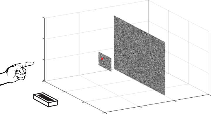
For experiments I–IV, the target and cursor were luminance-defined circles (61.5 cd/m2, 0.8° diameter; and 71.3 cd/m2, 0.3° diameter, respectively) on a gray background (52.4 cd/m2). Luminance was measured with a photometer (PR 655, Photo Research; Syracuse, NY) through the beam splitter and a polarizing lens. For experiment V, the target was a disparity-defined square (width = 0.8°) created by a DRES (Julesz and Bosche 1966; Norcia and Tyler 1984). Both the target and the background were composed of Gaussian pixel noise clipped at 3 SDs and set to span the range of the monitor output (mean = 52.4 cd/m2, maximum = 102.8 cd/m2, minimum = 2.043 cd/m2; see Fig. 12 for example). The cursor was a small red square (0.1°).
Fig. 12.
Schematic of the dynamic random element stereogram (DRES) stimulus. The target was constrained to be in front of the background. Both the target and the background were composed of Gaussian pixel noise that updated at 60 Hz.
Looming and focus cues (i.e., accommodation and defocus) are both known to be cues for motion-through-depth, but were not rendered in these stimuli. These cues would have been very small for real-world versions of our stimuli (see the general discussion for more details).
Analysis
Each trial resulted in a time series of target and response positions. To examine tracking performance, we calculated a cross-correlogram (CCG) for each trial of the target velocity and the response velocity for the relevant directions of motion (see e.g., Bonnen et al. 2015; Mulligan et al. 2013). A CCG shows the correlation between the target and response velocities as a function of time lag (temporal offset between target and response time series). An average CCG was computed per subject across all the trials in a condition. The CCGs can loosely be interpreted as causal filters or impulse response functions. In fact, for a linear system and white noise, the CCG is an estimate of the impulse response function.
The shape of the average CCG characterizes the overall latency and spatiotemporal fidelity of the tracking response. Some basic features of these CCG response functions (i.e., peak, lag, width) provide simple measures of performance in each condition. The peak is the maximum correlation value. The lag is temporal offset(s) at the peak correlation value. The width refers to the width of the CCG at one-half of the peak correlation (i.e., height). The lag provides a measure of response latency, while peak and width are related to the spatiotemporal fidelity. The median was chosen as a summary statistic for these features. While the average CCG was robust, outliers were observed on individual trials, particularly in low-amplitude conditions. To be consistent across all conditions in all experiments and avoid ad hoc methods for excluding outliers, we chose to report the median of the features (peak, lag, width). For each condition, the median and its 95% confidence intervals were estimated via bootstrapping. A boot-strapped data set was generated by resampling the original data set [e.g., the peaks for the horizontal direction for subject 1 (S1) in experiment I] with replacement. The median was calculated for that bootstrapped data set. This was repeated N times (N = 1,000). The median and 95% confidence intervals of those N medians are reported (see Figs. 3, 7, 9, 11, and 14). In many figures, the 95% confidence intervals may be hidden behind the plotted CCG curves because they are relatively small intervals.
Fig. 3.
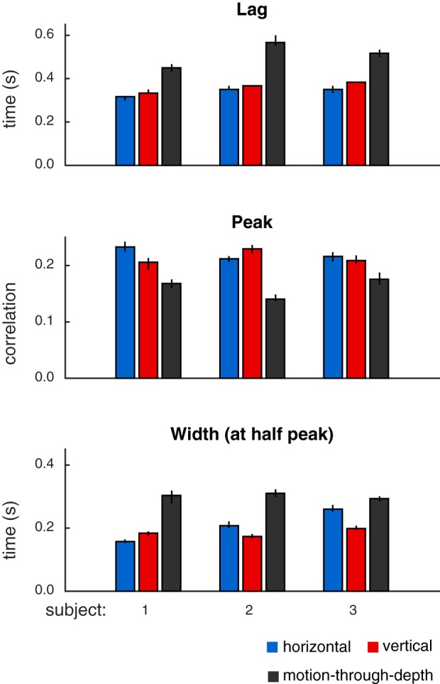
Summary of features of tracking performance in experiment I, calculated from CCGs shown in Fig. 2. Features (top: lags; middle: peaks; bottom: width at half peak) indicate consistently better performance (shorter lags, higher peak correlation values, and smaller CCG widths) for tracking frontoparallel motion compared with motion-through-depth for a target moving in a Brownian random walk. Bar height indicates median values, and error bars show 95% confidence intervals.
Fig. 7.
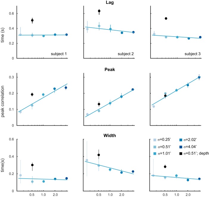
Summary of features of tracking performance for frontoparallel motion tracking and motion-through-depth tracking shown in Fig. 6. Color corresponds to condition, error bars indicate 95% confidence intervals, and the lines correspond to least squares fits of the frontoparallel data. Median lags (top row), median peak correlations (middle row), and median width (bottom row) values for all 3 subjects are shown. Peak correlation increases as a function of σ. Lag changes very little. Width has a negative relationship with σ. See Table 3 for slope values. With one exception (subject 3, peak), the point corresponding to depth tracking is clearly afield from the line describing the frontoparallel data.
Fig. 9.
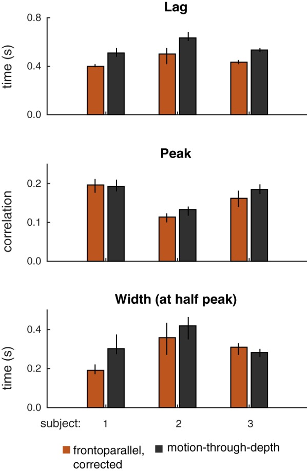
Summary of features of tracking performance for gain-corrected frontoparallel motion tracking and motion-through-depth tracking. Median lags (top), peak correlations (middle), and median widths (bottom) for motion-through-depth (black) and gain-corrected frontoparallel (brown) tracking for each of the subjects are shown. A pronounced and consistent difference in lags remains between motion-through-depth tracking and frontoparallel motion tracking. In the case of peak correlation and width, corrected gain accounts for the majority of the difference. Error bars represent 95% confidence intervals.
Fig. 11.
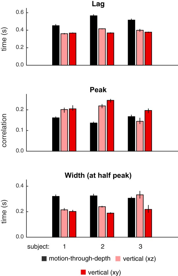
Summary of features of tracking performance from depth (black), vertical XZ (light red), and vertical XY (dark red) CCGs pictured in Fig. 10. Features (top: lags; middle: peaks; bottom: width at half peak) indicate consistent difference between motion-through-depth tracking and vertical XZ tracking. Bar heights indicate median values, and error bars show 95% confidence intervals.
Fig. 14.
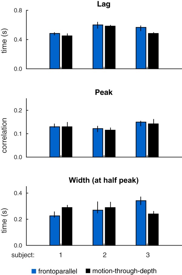
Summary of features of tracking performance from depth (black) and frontoparallel (blue) CCGs pictured in Fig. 13. Bar heights indicate median values, and error bars show 95% confidence intervals. Features (top: lags; middle: peaks; bottom: width at half peak) are similar across motion-through-depth tracking and frontoparallel tracking. In particular, the latency difference between frontoparallel motion tracking performance and motion-through-depth tracking performance is negligible or reversed (see Table 7).
We performed several planned comparisons of features across conditions in our experiments. For these comparisons, the effect size (effectively a d′) was calculated on the medians:
| (2) |
where m1 and m2 are the medians of the respective conditions and s1 and s2 are the standard deviations. Because the data contained outliers and did not meet the assumption of normality, we could not perform traditional Student’s t-tests for these comparisons. To evaluate significance, we sampled (N = 100,000) to obtain the distribution of differences between the medians in the two conditions in question. We report the cumulative probability that the difference is ≤0 as our significance value, where the difference is taken in the direction of the effect (effectively a one-tailed t-test for medians).
Experiment I. 3D Tracking
Observers tracked the center of a target as it moved in a 3D Brownian random walk. Analysis of the resulting time series (target path and subject’s response path) revealed a selective impairment for tracking motion-through-depth.
Methods.
In this experiment, observers were asked to track the center of a luminance-defined stereoscopic target as it moved in a 3D Brownian random walk (σ = 1 mm) using their finger to control a visible cursor. Note that, when referring to motion in each of the three dimensions, we will use the terms horizontal motion, vertical motion, frontoparallel motion (referring to horizontal and/or vertical motion), and motion-through-depth to remain consistent with existing literature. The term 3D motion will refer more generally to motion in all directions. The cursor motion was rendered to match the motion of the observer’s finger in space, such that, when the subjects moved their finger 1 cm in a direction, the cursor appeared to move 1 cm in that direction. Observers completed 50 such trials in blocks of 10.
Each trial yielded a pair of x-y-z time series: the position of the target in 3D space (i.e., the stimulus), and the position of the cursor (i.e., the observer’s response). For each trial, we computed a CCG (see, e.g., Bonnen et al. 2015; Mulligan et al. 2013) of the target velocity and the response velocity for the horizontal, vertical, and depth components. We report the average across all trials. In experiment I, the CCG functions are well fit by a skewed Gabor function (e.g., Geisler and Albrecht 1995), a sine function windowed by a skewed Gaussian (a Gaussian with two σ values, σ1 above the mean and σ2 below the mean):
| (3) |
| (4) |
where t is the function domain; a is the amplitude, μ is the mean and the offset of the sine wave, and σ1 and σ2 are the standard deviations, σ1 for t ≥ μ and σ2 for t < μ; for the sine function, ω is the frequency of the sine wave. The location of this function’s maximum value (i.e., the lag) is equal to . The skewed Gabor function was fit to CCGs using least squares minimization. The proportion of the variance explained was used to measure the goodness of fit. This measure was calculated by leave-one-out cross validation. All but one trial was used to perform the fit, then the correlation between the left-out trial and the fit was calculated. This value was squared to find the variance explained. This was repeated 50 times, once for each trial, and the average is reported.
Results.
Figure 1 shows tracking time series data for one subject from an example trial (20 s). Subjects were able to track the target (gray lines) in each of the cardinal directions (relative to the observer): horizontal (blue; left), vertical (red; middle), and depth (black; right).
Fig. 1.
Example of data generated by target tracking. These data were taken from a single trial completed by subject 1. Each subplot shows the position for a particular cardinal direction (horizontal, vertical, and depth) over time. In every panel, the thick gray line represents the target position. The thinner line in each panel represents the subject’s tracking response (horizontal, blue; vertical, red; depth, black).
Figure 2 shows the mean CCGs (dots) and 95% confidence intervals (cloud) for each of the three subjects, across all trials using the same color conventions as in Fig. 1. Skewed Gabor functions were fit to the CCGs (see Methods for details). The solid lines in Fig. 2 correspond to the fits. The proportion of the variance explained across subjects and cardinal directions ranges from 73 to 88%, with an average of 82% (see Table 1 for goodness-of-fit values per CCG).
Fig. 2.
Experiment I: 3D tracking. Tracking motion-through-depth is impaired relative to tracking frontoparallel motion. Average cross-correlograms (CCGs) are plotted (dots) for all 3 subjects for horizontal (blue), vertical (red), and motion-through-depth (black). The skewed-Gabor fits of those CCGs are plotted as solid lines. Here and in similar figures to follow, error clouds represent 95% confidence intervals on the data, although these error clouds are often not distinguishable from the data and/or fits. Notice the pronounced difference in tracking performance between frontoparallel motion (horizontal/vertical) and motion-through-depth.
Table 1.
The proportion of variance explained by the fits shown in Fig. 2
| Subject 1 | Subject 2 | Subject 3 | |
|---|---|---|---|
| Horizontal | 0.82 | 0.83 | 0.88 |
| Vertical | 0.79 | 0.83 | 0.83 |
| Depth | 0.83 | 0.73 | 0.84 |
Values are goodness of fit per CCG.
All subjects show a significant impairment for tracking motion-through-depth compared with horizontal and vertical motion. In particular, the depth CCG for each subject has a decreased peak correlation, increased lag (of that peak correlation), and increased width (at half peak) compared with either of the frontoparallel CCGs (horizontal and vertical). The differences in these features indicate a longer response latency and decreased spatiotemporal precision for tracking motion-through-depth in experiment I.
Figure 3 shows the median lag (first row), peak (second row), and width (third row) for the horizontal, vertical, and depth CCGs for each observer (error bars indicate 95% confidence intervals, see general methods for how these features are computed). We compared the features of motion-through-depth tracking performance to horizontal motion tracking performance to confirm our previous observations that the depth motion CCGs exhibit increased lags, decreased peaks, and increased widths (P < 1e-5 across all comparisons; see Table 2 for effect sizes and significance values). These differences are indicative of decreased performance in tracking motion-through-depth across all features.
Table 2.
Comparison of frontoparallel motion tracking (horizontal, blue, in Figs. 1, 2, and 3) and motion-through-depth tracking (black in Figs. 1, 2, and 3) in experiment I
| Subject 1 | Subject 2 | Subject 3 | |
|---|---|---|---|
| Lag | 2.78 (P < 1e-5) | 3.46 (P < 1e-5) | 3.10 (P < 1e-5) |
| Peak | 1.83 (P < 1e-5) | 1.75 (P < 1e-5) | 1.09 (P < 1e-5) |
| Width | 2.63 (P < 1e-5) | 0.84 (P < 1e-5) | 0.66 (P < 1e-5) |
Values are the effect sizes, with significance values in parentheses, for the difference of medians.
While there are differences between horizontal and vertical tracking CCGs, they are all relatively small and idiosyncratic to the observer. For example, notice that S1 shows a slightly lower peak and longer lag for vertical tracking compared with horizontal. Informally, we have observed that these individual differences are relatively stable across time and experimental condition (over the course of 2–3 yr of experiments in our laboratory). However, our primary interest is in the general differences in performance between frontoparallel and depth tracking. Therefore, we take horizontal tracking to be representative of frontoparallel tracking for the purposes of comparison.
Discussion.
In experiment I, observers tracked a target as it moved in a 3D Brownian random walk. Observers showed impaired tracking performance for tracking the motion-through-depth compared with the frontoparallel components of motion.
Two potential explanations for this relative impairment are as follows: 1) the egocentric geometry of motion-through-depth results in a smaller signal-to-noise ratio (SNR) (i.e., the size of the visual signals are much smaller for motion-through-depth vs. frontoparallel motion); and 2) the perception of motion-through-depth involves additional mechanisms to make use of binocular signals [e.g., interocular velocity differences (IOVDs), changing disparities (CD)]. Those additional mechanisms have different spatiotemporal signatures in the context of tracking.
The following experiments examine the contribution of these two explanations to the impairment of motion-through-depth tracking, with experiments II–IV focused primarily on the ramifications of geometry, and experiment V focused on the role of disparity processing.
Experiment II. Geometry of 3D Motion as a Constraint on Motion-Through-Depth Tracking Performance
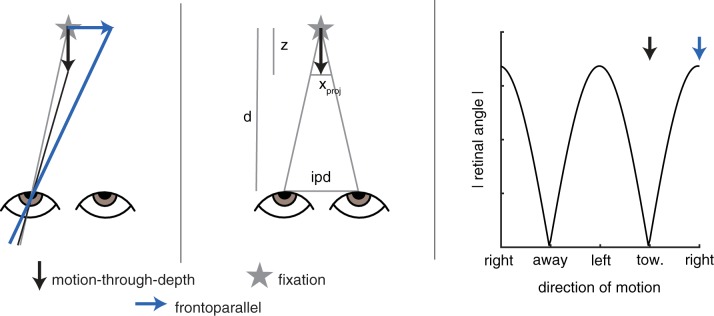
The magnitude of the retinal signal resulting from an environmental motion depends on the direction of the motion relative to the observer (see Fig. 4). In fact, when the viewing distance is large relative to interpupillary distance (allowing the small-angle approximation), frontoparallel motion and a motion-through-depth result in retinal projections with a relative size of ~1: ipd/d, where d is viewing distance and ipd is interpupillary distance. This approximation assumes that the viewing distance is large compared with the interpupillary distances (d >> ipd) and that the motion’s location (x) ≈ 0 (meaning that it has a horizontal position close to the midpoint between the two eyes). Both are true during the motion-through-depth condition of the following experiment (d = 85 cm, ipd = 6.5 cm, x = 0). The ratio is calculated by similar triangles, as shown in the diagram in Fig. 4, middle. For this experiment, the ratio is 1:0.08, meaning the motion-through-depth signal is <10% of the frontoparallel signal. This geometric reality greatly reduces the SNR for tracking motion-through-depth. We examined the ramifications of this geometry in two ways, 1) a set of simulations that used a Kalman filter observer and manipulated signal size and 2) a set of experiments that manipulated signal size for frontoparallel motion tracking, and then compared it to motion-through-depth tracking performance.
Fig. 4.
Frontoparallel motion and motion-through-depth produce differently sized retinal signals. Left: for an environmental motion vector that remains the same size, regardless of direction, the magnitude of the resulting motion on the retina (measured as the absolute angular difference, i.e., the difference between the gray line and the black/blue lines) is smaller for motion-through-depth (black) than for horizontal motion (blue). Middle: the approximation of the ratio of the size of the retinal projections for frontoparallel motion vs. motion-through-depth is calculated by similar triangles, making the assumption that d >> ipd and x = 0. From this diagram we see that ipd/d = xproj/z. Let z = 1, then xproj = ipd/d. Right: the magnitude of the motion on the retina (retinal angle, black line) is periodic over the environmental motion direction (left/right are large, and toward/away are small). Arrows show the two cases illustrated in the left panel.
For this set of experiments/simulations and all remaining experiments, we shift to reporting σ in arcminutes, because we are now concerned with size of the motion falling on the retina, and this is traditionally reported in degrees (or arcminutes) of visual angle. The standard ratio used to convert from millimeters of motion on the screen to arcminutes is simply , where atand is the arctangent in degrees, v is the motion on the screen, and d is the viewing distance.
Kalman filter observer.
We simulated tracking at different signal sizes using a Kalman filter observer (ideal observer for the behavioral tracking paradigm; Baddeley et al. 2003; Bonnen et al. 2015). It makes a set of testable predictions for how manipulating SNR should affect measures of performance (e.g., CCGs, peak, lag, and width).
Two equations form a simple linear dynamical system: the random walk of a stimulus (x1:T, see Eq. 1) and the corresponding noisy observations (y1:T) of an observer:
| (5) |
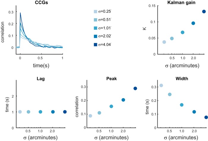
where xt is a target position, yt is the noisy observation of xt, σ2 is the parameter that controls the motion amplitude of the stimulus, R is the observation noise variance, and vt corresponds to a random variable drawn from N(0, R) at time t. (See appendix in Bonnen et al. 2015 for additional details.) In this formulation is the SNR. The Kalman filter provides an optimal solution for estimating xt given y1:t, σ2, and R. Using the Kalman filter as an observer, we simulated responses to a random walk with different values of σ while R remained fixed, effectively manipulating the SNR. Figure 5 summarizes the results of this simulation. The values of σ were chosen to correspond to those in experiment II (below). R was set to 200 arcmin so that the CCG in the maximum SNR condition had a peak response comparable to the empirical results observed in experiment II (below). Changing σ systematically changes the optimal Kalman gain (K), which specifies how much a new noisy observation is weighted relative to the previous estimate. The CCGs reflect those changes in the optimal Kalman gain, showing a decreased peak correlation (see Fig. 5, bottom middle) and increased width of the CCG (see Fig. 5, bottom right). The lag is unaffected (see Fig. 5, bottom left).
Fig. 5.
Performance of a Kalman filter observer. Top left: the change in the optimal Kalman gain (K) as a function of motion amplitude (σ). Larger values of σ result in larger values of K, which results in a higher weighting of new observations. Top right: average CCGs were calculated for simulated Kalman filter observer responses at each of the values of σ. Bottom left: crucially, lag was independent of σ. Bottom middle: higher values of σ resulted in higher peak correlations, indicating a higher spatiotemporal fidelity. Bottom right: higher values of σ resulted in lower widths at half height, indicating a higher temporal precision in the response.
Changes in SNR due to geometry predict some of the differences between frontoparallel motion tracking and motion-through-depth tracking observed in experiment I: a drop in the CCG peak and an increase of the width of the CCG, but not the change in lag. The following experiment examines the effects of manipulating SNR on human performance, compares human performance to the Kalman filter observer, and makes a comparison between tracking frontoparallel motion and motion-through-depth.
Methods.
As in experiment I, observers tracked the center of the target using their finger to control the cursor. A trial consisted of 20 s of tracking the target. In this experiment, observers always tracked one-dimensional Brownian random walks as in Eq. 1. We manipulated σ, thus controlling the distribution of the size of the motion steps across blocks of trials.
There were two distinct conditions: frontoparallel motion tracking and motion-through-depth tracking. In the frontoparallel motion tracking, observers tracked the target as it moved left and right on the x-axis. The motion corresponded to a one-dimensional Brownian random walk at σ = 4.04, 2.02, 1.01, 0.51, 0.25 arcmin; or in pixels at σ = 3.49, 1.75, 0.87, 0.44, 0.22, well within the subpixel capabilities of the Psychophysics Toolbox. Cursor responses were also confined to the x-axis. In the motion-through-depth tracking, observers tracked the target as it moved back and forth along the z-axis. The horizontal projections of the depth motion corresponded to a one-dimensional Brownian random walk at σ = 0.51 arcmin. Cursor responses were confined to the z-axis.
The geometry of the stimulus/cursor was drawn to match the observers’ motion in space, such that when the subject moved his/her finger 1 cm in a direction, the cursor appeared to move 1 cm in that direction. Observers completed 20 trials in blocks of 10 at each value of σ (indicated previously). The experiment was block-randomized.
Results.
Figure 6 summarizes the results from this set of experiments in the form of CCGs, whereas Fig. 7 plots the lags (top row), the peak correlations (middle row), and the width-at-half-peak (bottom row) for each condition.
Fig. 6.
Experiment II. Manipulating motion amplitude demonstrates that impairments to motion-through-depth tracking are not purely the result of the smaller SNR. Average CCGs for frontoparallel motion tracking across the 5 different motion amplitudes are shown in blue. Decreased motion amplitude results in decreased tracking performance, primarily manifesting as a decreased peak, with no appreciable change in lag. These behavioral results are comparable to the predictions made in the simulations (see Fig. 5). The average CCG for the motion-through-depth tracking condition is shown in black. Motion-through-depth tracking performance has an obviously increased lag compared with frontoparallel motion tracking performance; i.e., the peak of the depth CCG is right-shifted compared with the frontoparallel CCGs. The motion amplitude in the motion-through-depth condition matches the second smallest motion amplitude in the frontoparallel motion conditions. However, for subjects 1 and 2, the peak of the depth CCG does not match the peak of the frontoparallel condition with comparable motion amplitude. The peak of the depth CCG is actually more consistent with a higher motion amplitude. Error clouds represent 95% confidence intervals on the data.
frontoparallel motion tracking.
Tracking performance decreases with decreasing motion amplitude, as evidenced by the systematic changes in the CCGs (blue) in Fig. 6. This manifests specifically as an increased peak and decreased width for an increased σ, with little to no change in the lags (slopes reported in Table 3). The changes to frontoparallel motion tracking performance with the manipulation of SNR are inconsistent with the impaired motion-through-depth tracking found in experiment I in important ways: 1) decreasing motion amplitude does not shift the lag of responses; and 2) the horizontal projections corresponding to motion-through-depth tracking in the original experiment have a σ of ~0.25 arcmin. Motion-through-depth tracking performance in experiment I, as measured by peak correlation (medians of 0.17, 0.14, and 0.18 for each subject, respectively) is better matched by higher σ values in the frontoparallel motion tracking condition experiment.
Table 3.
Linear fits of lag, peak, and width for changing amplitude in experiment II
| Subject 1 | Subject 2 | Subject 3 | |
|---|---|---|---|
| Lag | 0.001 (R2 = 0.03) | −0.025 (R2 = 0.55) | −0.015 (R2 = 0.54) |
| Peak | 0.058 (R2 = 0.94) | 0.057 (R2 = 0.99) | 0.060 (R2 = 0.95) |
| Width | −0.006 (R2 = 0.05) | −0.050 (R2 = 0.86) | −0.016 (R2 = 0.56) |
Values are the slopes, with R2 values in parentheses.
relationship of results to kalman observer.
The observed behavioral changes with the manipulation to SNR are consistent with those predicted by the Kalman observer: little change in lag, a drop in the CCG peak, and an increased CCG width (see Figs. 5–7). We should note that the simulations predict a stronger relationship between width and σ value than we observed. We believe that this is largely due to limitations in the Kalman filter as an ideal observer of human behavior. Human observers do not have perfect signal transmission of position/motion through the visual system. Previous work has described monocular/binocular temporal filters that would impart some of the features observed in our CCGs, particularly the negative lobes (Neri 2011; Nienborg et al. 2005). This difference in shape due to temporal filters would likely have an effect on our measures of width.
motion-through-depth tracking.
Subjects performed an additional motion-through-depth tracking condition to generate data directly comparable to the frontoparallel motion tracking condition in this experiment, i.e., visual signal size matched the second smallest motion amplitude condition performed during frontoparallel motion tracking (σ = 0.51 arcmin). This CCG corresponding to this condition is plotted in black in Fig. 6. The motion amplitude of this condition makes it directly comparable to the frontoparallel condition marked by the second lightest shade of blue lines/symbols in Figs. 6 and 7. We compared the peak, lag, and width of the CCGs for these two conditions (see Table 4 for effect sizes and significance values). Again, motion-through-depth tracking performance exhibits an increased lag not present in the frontoparallel motion tracking (P < 1e-5). For S1 and subject 2 (S2), the peak correlation for motion-through-depth tracking was better matched by a higher value of σ in the frontoparallel motion condition (P < 1e-5), but for S3 there was no significant difference (P = 0.07).
Table 4.
Comparison of motion-through-depth tracking and frontoparallel motion tracking at σ = 0.51 arcmin in experiment II
| Subject 1 | Subject 2 | Subject 3 | |
|---|---|---|---|
| Lag | 1.84 (P < 1e-5) | 2.19 (P < 0.1e-5) | 7.73 (P < 1e-5) |
| Peak | 1.77 (P < 1e-5) | 1.50 (P < 0.1e-5) | 0.40 (P = 0.07) |
| Width | 2.16 (P = 1e-5) | 0.39 (P = 0.02) | 1.69 (P < 1e-5) |
Values are the effect sizes, with significance values in parentheses, for the difference of medians.
Discussion.
Changing motion amplitude (as we have done in this experiment) is in essence changing the range of retinal signal sizes and thus the overall SNR, given some fixed level of internal noise. Tracking performance (as measured by peak, i.e., spatial fidelity) does decrease with decreasing motion amplitude, and it is reasonable to conclude that the difference in visual signal size contributes to the impairment to motion-through-depth tracking.
However, a direct comparison of frontoparallel motion and motion-through-depth tracking performance when visual signal size is equivalent (at σ = 0.51 arcmin) revealed substantial differences in performance. Motion-through-depth tracking had an increased latency and for some subjects different spatial fidelity. Based on these results, we conclude that the impairment to tracking depth motion observed in experiment I is not completely explained by the difference in visual signal size due to geometry.
Experiments III and IV address concerns about whether differences in performance are due to differences in motor control. Experiment III changes the cursor motion in the frontoparallel motion condition so that it matches the cursor motion-to-visual signal size ratio of the motion-through-depth condition. This accounts for much of the remaining difference in the spatial fidelity of the tracking response. Experiment IV examines whether physical differences in arm motion direction play a significant role in tracking performance.
Experiment III. Frontoparallel Cursor Motion Consistent with Motion-Through-Depth Tracking
The one component of the geometry not equivalent across frontoparallel motion tracking and motion-through-depth tracking in experiment II was the cursor gain. We intentionally drew the cursor to match the observers’ motion in space, so that when the subject moved his/her finger 1 cm in a direction, the cursor appeared to move 1 cm in that direction. Consider the motion-through-depth and frontoparallel motion conditions where retinal motion amplitude was equivalent (σ = 0.51′). Because retinal signals of equal size result in much larger environmental motions in depth, subjects had to move more on average in the motion-through-depth conditions. That difference in movement also provides finer control of the cursor and may cause delays during depth motion tracking. In this experiment, subjects performed frontoparallel motion tracking using a cursor with the same gain as motion-through-depth tracking (i.e., larger finger motion was required).
Methods.
As in experiment II, observers tracked the target as it moved in a one-dimensional Brownian random walk along the x-axis (at σ = 0.51 arcmin). Like the regular frontoparallel motion tracking condition, cursor responses were confined to the x-axis. However, the gain of the cursor motion was set to match the gain associated with motion-through-depth tracking, such that a larger motor movement was required to produce a relatively small cursor movement. Each subject completed 20 trials in this condition.
Results.
Changing the cursor gain to match the visual signal size does have an impact on tracking performance. Figure 8 illustrates that frontoparallel, gain-corrected tracking performance more closely resembles motion-through-depth tracking (replotted in black) than frontoparallel tracking only (see Fig. 6 for reference).
Fig. 8.
Experiment III. Cursor motion consistent with visual signal size (i.e., gain-corrected) still cannot account for the difference in latency for motion-through-depth tracking. The average CCG for the condition with gain-corrected cursor motion is shown in brown. The average motion-through-depth tracking CCG from experiment II (see Fig. 6) is replotted in black for each subject. Error clouds represent 95% confidence intervals on the data. The gain-correction accounts for some of the difference between frontoparallel motion and motion-through-depth tracking seen in experiment I. However, there remains an increased lag for motion-through-depth tracking (P < 1e-3 for all subjects; see Table 5).
Figure 9 shows the remaining differences between performance for motion-through-depth tracking vs. gain-corrected, frontoparallel motion tracking (see Table 5 for difference values and associated P values). Even in the gain-corrected frontoparallel motion tracking, there was still a difference in lag compared with motion-through-depth tracking, while the difference in CCG peak height diminished substantially. The CCG width only remained significantly different only in the case of S1.
Table 5.
Comparison of gain-corrected frontoparallel motion tracking and motion-through-depth tracking performance in experiment III
| Subject 1 | Subject 2 | Subject 3 | |
|---|---|---|---|
| Lag | 2.55 (P < 1e-5) | 0.55 (P = 1e-3) | 0.87 (P < 1e-5) |
| Peak | 0.08 (P = 0.40) | 0.58 (P = 0.01) | 0.48 (P = 0.09) |
| Width | 1.54 (P < 1e-5) | 0.23 (P = 0.15) | 0.22 (P = 0.05) |
Values are the effect sizes, with significance values in parentheses, for the difference of medians.
Discussion.
The impaired performance in motion-through-depth tracking originally demonstrated in experiment I is partially explained by geometry, as illustrated in experiments II and III. However, there remains at least an unexplained lag (or increased latency) in the motion-through-depth tracking response. One possibility that must be eliminated is that this temporal delay is simply due to motor differences between frontoparallel motor movements (left, right, up, down) and depth motor movements (forward and backward).
Experiment IV. Frontoparallel Cursor Motion and Cursor Control Consistent with Motion-Through-Depth Tracking
During tracking, subjects move their finger left and right, up and down, and back and forth. Each of the cardinal directions is tied to one of these arm/finger motions. It is possible that some or all of the latency differences are due to the different motor demands of moving the arm/finger back and forth. To determine the contribution of these motor differences, subjects performed a frontoparallel motion tracking task in which we manipulated whether a subject controlled XY cursor motion with XY finger motion (as in all of the previous experiments) or controlled XY cursor motion with XZ finger motion (as one does when using a mouse or trackpad where motion toward the screen moves the cursor up the screen).
Methods.
Observers tracked the target as it moved in a 2D Brownian random walk (σ = 4.04 arcmin) in xy space. Cursor responses were confined to the x- and y-axes. In the XY condition, finger motion along the y-axis controlled cursor motion on the y-axis. In the XZ condition, finger motion along the z-axis controlled cursor motion on the y-axis. Each trial was 20 s, and two observers performed 50 trials in each condition.
Results.
Average CCGs were calculated for the horizontal and vertical motion (see Fig. 10). Note that S1 shows nearly identical performance across the two conditions. The main question here is whether the motor demands of moving forward and backward could result in the impairments observed in experiment I. Thus the main comparison here is between the vertical motion XZ tracking performance and the motion-through-depth tracking.
Fig. 10.
Experiment IV. Manipulating the finger motion axis (XY vs. XZ) cannot account for the difference between frontoparallel and motion-through-depth tracking. Average CCGs are shown for XY motion tracking using XY finger motion (solid lines) and using XZ finger motion (dashed lines), where the horizontal motion CCGs are in blue, and the vertical motion CCGs are in red. The average depth CCG from experiment I is replotted in black for convenient comparison. Error clouds represent 95% confidence intervals on the data.
Features of tracking performance are calculated for motion-through-depth, vertical XZ, and vertical XY (see Fig. 11). The comparison of interest is between vertical XZ and motion-through-depth, but vertical XY is provided for reference. The comparison between features of vertical XZ tracking and motion-through-depth tracking performance demonstrates large differences in tracking performance for most features/subjects (see Table 6). Again, there is a consistent difference in the lags.
Table 6.
Comparison of vertical tracking with XZ finger motion and motion-through-depth tracking performance in experiment IV
| Subject 1 | Subject 2 | Subject 3 | |
|---|---|---|---|
| Lag | 0.60 (P < 1e-5) | 2.45 (P < 1e-5) | 1.70 (P < 1e-5) |
| Peak | 0.89 (P < 1e-5) | 1.97 (P < 1e-5) | 0.52 (P = 0.01) |
| Width | 1.02 (P < 1e-5) | 0.67 (P < 1e-5 | 0.22 (P = 0.03) |
Values are the effect sizes, with significance values in parentheses, for the difference of medians.
Discussion.
Tracking XY motion in XZ does not account for the huge differences in lags between frontoparallel motion and motion-through-depth tracking observed in experiment I. The largest difference remaining between motion-through-depth tracking and frontoparallel motion tracking is that disparity computations are required to perform the motion-through-depth tracking. We hypothesized that the remaining response delay for motion-through-depth tracking in experiment III is the consequence of disparity processing. This hypothesis is explored in experiment V.
Experiment V. Disparity Processing as a Constraint on Motion-Through-Depth Tracking Performance
Previous experiments cannot entirely account for the difference between frontoparallel motion tracking and motion-through-depth tracking performance. The remaining difference is primarily in the latency of the tracking response. However, frontoparallel motion tracking does not require processing of binocular signals, e.g., binocular disparities or IOVDs. In this experiment, we imposed disparity processing on frontoparallel motion tracking. Subjects tracked disparity-defined target created by a DRES as it moved in a 3D random walk. We also applied what was learned in experiments II and III, adjusting the amplitude of the depth motion to increase its visual signal size, and matching the cursor gain across directions.
Methods.
In this experiment, observers were asked to use their finger to track the center of a disparity-defined square target created by a DRES (see Fig. 12 and general methods), using a cursor (small red luminance square). The geometry of the stimulus/cursor was drawn as in experiment III, so that the geometry of the cursor motion was matched across frontoparallel and depth motion according to visual signal size. A trial consisted of 20 s of tracking the target as it moved in 3D Brownian random walk (σ = 2.02′ in horizontal and vertical dimensions, σ = 0.79′ in depth). The size of σ for depth was adjusted per subject, so that the average CCG height matched; however, σ was the same for all three subjects. Observers completed 30 trials in blocks of 10.
Results.
Figure 13 summarizes the results from this experiment. Average CCGs are shown for frontoparallel motion and depth motion directions. The latency difference present previously is now negligible. The amplitude adjustment required to match the CCG peak height was a ratio of 1:6 for frontoparallel vs. depth. This is much smaller than ~1:15.4 predicted by the size of the disparity signal alone (1: distance/ipd, where viewing distance was 100 cm and ipd was 6.5 cm).
Fig. 13.
Experiment V. Imposing disparity processing on frontoparallel motion results in performance similar to motion-through-depth. Average CCGs for frontoparallel motion (blue) and motion-through-depth (black) during DRES tracking are shown. Error clouds represent 95% confidence intervals on the data. The latency difference between the frontoparallel motion and motion-through-depth CCGs is negligible or reversed (subject 3; see Table 7).
Figure 14 shows the peak, lag, and widths for frontoparallel and depth motion. The lags for all subjects are either not significantly different or reversed, the peaks are not significantly different (by design), and the widths are not significantly different for S2 (see Table 7 for effect sizes and significance).
Table 7.
Comparison of frontoparallel motion tracking and motion-through-depth tracking performance in experiment V
| Subject 1 | Subject 2 | Subject 3 | |
|---|---|---|---|
| Lag | 0.29 (P = 0.04) | 0.10 (P = 0.20) | 1.00 (P = 0.002) |
| Peak | 1e-3 (P = 0.61) | 0.19 (P = 0.38) | 0.21 (P = 0.22) |
| Width | 0.15 (P = 0.03) | 0.05 (P = 0.21) | 0.84 (P < 1e-5) |
Values are the effect sizes, with significance values in parentheses, for the difference of medians.
Discussion.
By creating a disparity-defined target, we imposed binocular disparity processing on frontoparallel motion tracking and removed monocular cues and IOVDs as potential sources of information. This resulted in nearly matched latencies between frontoparallel motion and motion-through-depth tracking. Although motion-through-depth amplitude had to be adjusted to better match the CCG peak height across directions, it did not have to be adjusted as much as is predicted by the geometry of visual signal size. It is possible that motion along the depth axis is privileged in disparity processing (see general discussion).
GENERAL DISCUSSION
Our primary finding was that tracking performance involves an impairment for the perception of motion-through-depth relative to frontoparallel motion. This is consistent with limitations found for vergence vs. version responses during eye tracking of visual targets (Mulligan et al. 2013; see their Fig. 4), demonstrating that this perceptual impairment is still present in the much “quicker” oculomotor plant. After accounting for differences in visual signal size, this impairment to the perception of motion-through-depth is primarily a temporal difference, a lag in the response, which is attributed to disparity processing.
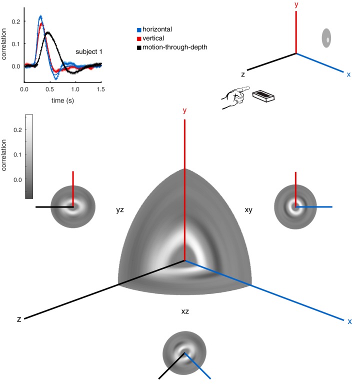
Throughout the course of this paper, we have examined and directly compared frontoparallel motion and motion-through-depth tracking performance. However, the data in experiment I were collected for target/cursor motion in all directions, not for the cardinal directions in isolation. The choice to perform the CCG analysis on the cardinal directions was an arbitrary one in many respects. We can describe the tracking performance in greater detail by systematically calculating a CCG for axes of motion along the sphere of possible directions. Figure 15 shows such an analysis for S1. The CCGs are calculated at 5° intervals around the XY, XZ, and YZ planes. Then the CCGs are plotted as a heatmap in polar coordinates, where θ is the direction of motion on which the CCG was calculated, and ρ is the lag. The main 3D heatmap shows CCGs from the XY, XZ, and YZ planes simultaneously. The smaller 2D heatmaps show the analysis on each of the three planes. Note that this analysis is sign-invariant, and thus there is 180° rotational symmetry.
Fig. 15.
Tracking performance across many directions. Here we show an analysis of tracking performance extended to all possible motion directions for subject 1. Top left: the CCGs for the cardinal motion directions are replotted from experiment I, Fig. 2. Top right: a schematic of the tracking paradigm in experiment I. A subject tracks a circular target, reporting its position by controlling a cursor with his/her pointer finger. Bottom: the main 3D heatmap (center) shows CCGs from the xy, xz, and yz planes simultaneously, where the gray scale axis represents correlation, θ is the direction of motion, and ρ is the lag (see text for additional details). We also show the full CCG heatmap for each plane: xy, xz, and yz. Note the elongation of the peak correlation ridge near the z-axis, and the presence of negative lobes on the xy plane, but not along the z-direction in the other two planes.
The peaks of the CCGs on the 2D heatmaps form visible “rings.” These rings are fairly circular for the XY (frontoparallel) plane, i.e., frontoparallel motion tracking. This is unsurprising given the relative consistency between the previously calculated vertical and horizontal CCGs. The same analyses for the YZ (sagittal) plane and the XZ (horizontal) plane are also shown. The elliptical nature of these heat maps clearly demonstrates the difference in depth vs. frontoparallel, while also revealing the progression of tracking characteristics in between.
Frequency-Domain Analysis of 3D Motion Tracking
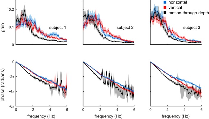
Here we reexamined the results of experiment I in the frequency domain. The frequency domain responses were computed on a trial-by-trial basis, and the resulting amplitude and phase responses were averaged within subject and condition to yield mean gains and phase lags as a function of temporal frequency. Figure 16 summarizes this analysis. It contains a Bode plot for each of the three subjects. The top row shows the response gain as function of frequency, and the bottom row the phase (absolute, unwrapped) as a function of frequency.
Fig. 16.
Bode plots showing the responses of the three subjects (columns) in the temporal frequency domain. The top row shows response gain, and the bottom row shows response phase, both as a function of frequency. Consistent with the time domain cross-correlation analysis, all subjects show a larger response lag for motion-through-depth tracking relative to frontoparallel tracking (bottom row). Moreover, response gain is higher for frontoparallel tracking above ∼1.5 Hz, and, for two of the three subjects, response gain for motion-through-depth tracking peaks at a lower temporal frequency than it does for frontoparallel tracking. Shaded regions show bootstrapped 95% confidence intervals.
Recall that the stimulus motion was a Brownian random walk in position and Gaussian white noise in velocity. Thus the stimulus velocities were also Gaussian white noise in the frequency domain. Although all frequencies are equally represented in the stimulus, the analysis presented in Fig. 16 demonstrates that subjects primarily track the low frequencies, and that this is even more pronounced for motion-through-depth tracking compared with frontoparallel tracking. Note also the consistently larger phase lags for motion-through-depth tracking where reliable responses were obtained. This result is supported by previous psychophysical and electrophysiological work that demonstrated poorer temporal resolution for disparity modulation (Lu and Sperling 1995; Nienborg et al. 2005; Norcia and Tyler 1984) compared with contrast modulation (Hawken et al. 1996; Kelly 1971, 1976; Williams et al. 2004). Furthermore, the inability to track higher frequency modulations also provides a reasonable explanation for why the correlation values in the reported CCGs are overall quite low.
The Role of Visual Signal Size in Motion-Through-Depth Tracking Performance
Experiment II explored the role of visual signal size and SNR in tracking performance by manipulating frontoparallel motion and motion-through-depth tracking so that they had matched visual signal size. We concluded that subjects’ depth tracking performance had an increased latency and an improved spatial fidelity (for 2 of 3 subjects) compared with the frontoparallel condition (see Fig. 7). A follow-up experiment (III) suggested that the observed spatial improvement was actually related to the gain on cursor control, leaving just a latency difference between the characteristics of motion-through-depth tracking and frontoparallel motion tracking.
It is surprising that the overall spatial fidelity of motion-through-depth tracking performance and frontoparallel motion tracking performance is approximately equal (after we account for the differences of geometry). Classical demonstrations of “stereomotion suppression” (Tyler 1971) led us to expect that subjects should show spatial fidelity deficits in motion-through-depth tracking performance relative to frontoparallel. However, the differences in our experimental task provide an explanation. In Tyler (1971), subjects set the amplitude of a sinusoidal motion at the threshold of their perception. The moving bar oscillated sinusoidally either in depth or horizontally about a reference. Thresholds were consistently higher for depth motion across all frequencies, i.e., two eyes were less sensitive than one at threshold. Thresholds for frequencies >0.5 Hz were consistently between 0.2 and 0.8 arcmin. Similar threshold ranges have been found for static disparities (Badcock and Schor 1985), which may be a better comparison since our motion stimulus is not a single sinusoid. In our experiment, subjects tracked a target moving in all directions with a visible cursor. They were instructed to keep the cursor center on the target in all dimensions (or one, depending on the condition). We examined distribution of disparity between the target and the cursor (see Fig. 17) during the motion-through-depth tracking task in experiment II. Given a conservative threshold of 50 arcsec (Badcock and Schor 1985; Tyler 1971), a high proportion of the trials are spent with the target and the cursor at suprathreshold relative disparities (83, 86, and 84% for each subject, respectively). This high proportion of suprathreshold disparities provides a plausible explanation for why we do not observe the deficits that might be predicted by previous work on disparity processing.
Fig. 17.
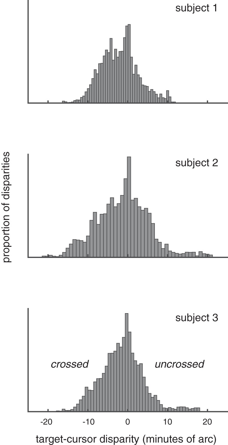
Histogram of relative disparity between target and cursor at each time step (0.1667 s) across all motion-through-depth tracking trials (see experiment II) for each of the subjects. Given a conservative estimate of disparity threshold (50 arcmin), these histograms demonstrate that subjects spent a high proportion of the trials (83, 86, and 84% for each subject, respectively) with the target and the cursor at suprathreshold relative disparities.
Potential Cue-Conflicts: Accommodation, Defocus, and Looming
There are several known cues for motion-through-depth that have not been rendered for these experiments (accommodation, defocus, and looming). The absence of these cues has the potential to cause cue-conflict for motion-through-depth stimuli. However, based on further analysis of the results and comparisons to the perceptual thresholds for those cues, the presence of cue-conflicts is unlikely.
Figure 17 demonstrates that the bulk of relative disparities in our experiment were between −10 and +10 arcmin, or roughly −0.5 to + 0.05 diopters (D). Accommodation thresholds are conservatively ~0.1 D (Wang and Ciuffreda 2006). Given the relative disparities between the cursor/target and the assumption that during a trial subjects were looking at the target or the cursor (or somewhere in between), we can conclude that the majority of the time accommodation cues were subthreshold. Similarly, the depth of field of the eye is typically reported as between 0.1 and 0.5 D (Walsh and Charman 1988), and thus the range of predicted disparities is well below that threshold.
In the case of looming, the extent of the motion relative to viewing distance is quite small. The maximum extent in depth (either toward or away) is 5 cm from the starting point; the mean is 2.4 cm. This translates to a maximum change in target size of 3.1 arcmin and a mean of 1.5 arcmin over the course of a 20-s trial. The change per stimulus update (20 Hz) was smaller: a maximum of 0.4 arcmin and mean of 0.2 arcmin. Looming has been studied primarily with stimuli moving in a sinusoid. Motion-through-depth based on looming cues alone are detectable when the amplitude of the oscillations are 0.5–2 arcmin, depending on the frequency (Regan and Beverley 1979). While the change over the course of the trial is in the perceptible range, the individual stimulus updates are not. Furthermore, our stimuli moved in a random walk, resulting in a looming cue that lacked a consistent change in size over time, which would probably result in higher thresholds for detection.
Binocular Cues for Perception of Motion-Through-Depth
With the results of experiments I–IV in mind, we considered the remaining impairment, which was primarily a difference in response latency. Even after accounting for the geometry inherent in depth motion, the perception of motion-through-depth appears to involve binocular mechanisms that exhibit different spatiotemporal signatures in the context of tracking.
Experiment V examined the role of disparity processing (a binocular mechanism) in tracking. We generated a disparity-defined target using a DRES (Julesz and Bosche 1966; Norcia and Tyler 1984). Imposing disparity processing on frontoparallel motion tracking removed the latency differences between frontoparallel motion and motion-through-depth tracking, suggesting that the latency difference is a signature of binocular disparity processing.
Psychophysical and electrophysiological work has shown a poor temporal resolution for disparity modulation (Nienborg et al. 2005; Norcia and Tyler 1984) compared with contrast modulation (Kelly 1971, 1979). Psychophysical work on static disparities also shows evidence for a temporal delay (>100 ms) for binocular disparity processing (Neri 2011). Nienborg et al. (2005) provides an explanation for the poorer temporal resolution in processing binocular disparities that explain both the behavioral and neuronal temporal resolution deficits observed in previous work. Although the differences in temporal resolution between disparity modulation and contrast modulation appear to suggest separate mechanisms for disparity tuning and contrast tuning, they can be explained by a binocular cross-correlation (i.e., disparity energy model; Ohzawa 1998). Models of disparity selectivity in neurons require the calculation of the cross-correlation between signals from the left and the right eye, temporally broadband monocular images that are already band-pass filtered. The result of the cross-correlation of prefiltered signals is a low-pass response for binocular signals compared with the equivalent monocular signal. Thus poorer temporal resolution is expected for responses to disparity signals; this may be related to the temporal deficits observed for motion-through-depth tracking and disparity in particular in our experiments.
Neri (2011) also suggests that some of the temporal dynamics of disparity processing are due to a rigid order for processing in which coarse processing precedes and constrains the finer, more detailed processing, an idea that is supported by electrophysiological work (Menz and Freeman 2003; Norcia et al. 1985). In fact, Samonds et al. (2009) demonstrates that disparity selectivity may continue to sharpen as much as 450–850 ms after stimulus onset. Qualitatively similar results have been found in V1 for orientation (Ringach et al. 2003) and spatial frequency (Bredfeldt and Ringach 2002), although these sharpening effects appear to evolve over shorter time scales than those found for disparity processing. Further work is needed examining the temporal dynamics of physiological responses to static disparities and CD, to better understand its connection to temporal dynamics in behavior.
This experiment and its conclusions focus primarily on a single binocular cue: changing disparity. However, there are two potential binocular sources of information for motion-through-depth: IOVDs and CD. In principle, these provide the same information. However, they differ in the order of operations resulting in either a binocular comparison of velocities (IOVD) or a temporal comparison of disparities (CD). Researchers have debated which of these cues is predominant in the visual system (Cumming and Parker 1994; Czuba et al. 2011; Rokers et al. 2009). Unfortunately, the nature of the target-tracking task is such that we cannot isolate the IOVD cue, like we isolated the CD cue in experiment V.
It is also worth noting that the statistics of the random walks used across all of the experiments in this work may not result in motion stimuli that are ideal for IOVD cues. The frontoparallel and depth noise velocities were white, meaning that the velocity at a given time point was not correlated with the time points around it. This means that the IOVD signal is not as predictable as the CD signal, which involves comparing positions that are correlated and is consistent with the notion that the IOVD signal does not have a huge effect on motion-through-depth tracking performance in this paradigm. Recent work suggests that the visual system might use different sources of binocular information, depending on the relative fidelity of cues in a situation or the demands of a particular task (Allen et al. 2015).
Privilege for Processing Motion-Through-Depth in Disparity-Limited Stimuli?
The stimulus used in experiment V adjusted the depth motion amplitude so that the CCG peak height was matched between horizontal and depth motion directions. The same motion amplitude value was used across all three subjects. However, this value was not as high as the ratio derived for the relationship between the magnitude of frontoparallel motion and the retinal projections of depth motion (1: ipd/d, see introduction to experiment II). The conclusion that we draw from this is that perhaps there is a privilege for processing binocular disparities associated with motion-through-depth.
However, there is little existing evidence to support this observation. Apparent motion studies using Julesz’s dynamic random dot stereogram (Julesz and Bosche 1966) for left-right motion detection and toward-away motion detection find comparable detection thresholds of ~5 Hz (Julesz and Payne 1968; Norcia and Tyler 1984). This is clearly not a privilege for depth motion, but, unlike experiments with monocular cues, it did not find a deficit for motion-through-depth.
Regan and Beverley (1973a) examined detection of “sideways” vs. depth motion in random dot stereograms (not dynamic, so there were still monocular cues). At the very slowest frequencies, the detection thresholds were comparable in one subject, but, for the most part, monocularly viewed motion detection thresholds were better. In addition, early work with oscillating bars demonstrated better motion detection for monocularly viewed vs. stereoscopically viewed oscillating bars (Regan and Beverley 1973b; Tyler 1971), with the potential exception of the ±5 arcmin around fixation (Regan and Beverley 1973b). These findings do not support the idea that there is a privilege for processing binocular disparities associated motions-through-depth. However, the stimuli used in these previous experiments were not purely disparity defined. It is possible that the monocular cues present in the stimuli obscure the privilege for motions-through-depth during disparity processing.
More work is needed to show if there is indeed a privilege for motion-through-depth in disparity-defined stimuli, and in particular to establish how it changes from threshold to suprathreshold motions, across different types of motion stimuli (i.e., from motion that oscillates to random walks).
Conclusions
Despite the crucial importance of egocentric depth motion, we found significant impairment for depth motion perception compared with frontoparallel motion perception. However, closer examination revealed that these deficits were relatively consistent with the geometry of the stimulus and the limitations of the binocular mechanisms used to perceive the motion.
DISCLOSURES
No conflicts of interest, financial or otherwise, are declared by the authors.
AUTHOR CONTRIBUTIONS
K.L.B., A.C.H., and L.K.C. conceived and designed research; K.L.B. and L.K.C. performed experiments; K.L.B. and L.K.C. analyzed data; K.L.B., A.C.H., and L.K.C. interpreted results of experiments; K.L.B. and L.K.C. prepared figures; K.L.B. and L.K.C. drafted manuscript; K.L.B., A.C.H., and L.K.C. edited and revised manuscript; K.L.B., A.C.H., and L.K.C. approved final version of manuscript.
APPENDIX A: LEAP MOTION CONTROLLER
A Leap Motion controller was used to collect measurements of 3D position (x,y,z in mm of our observers’ fingers). The Leap Motion controller is a 8 cm × 1 cm × 3 cm USB device that uses two infrared cameras and an infrared light source to track hands, fingers, and “finger-like” tools, reporting back positions and orientations. A line drawing of the device is shown in Fig. A1. Leap Motion reports that the device has a field of view of 150°, with an effective range of 2.5−60 cm above the device (1 in. to 2 ft.). To acquire coordinates in Matlab, we used an open source Matlab interface for the Leap Motion controller written by Jeff Perry (https://github.com/jeffsp/matleap).
We conducted two experiments to establish the precision of the Leap Motion controller in the context of our task. The first experiment evaluated the spatial precision of the Leap Motion controller. The second experiment measured both the temporal accuracy (lag) and precision.
Spatial Precision of Leap Motion Controller
Methods.
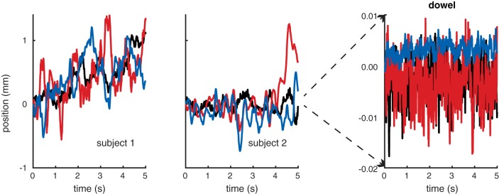
The apparatus was the same as in the original experiment (see general methods). Two subjects (S1 and S2 from above) were asked to point their pointer finger and remain stationary above the Leap Motion controller for 5 s. The same process was repeated for a wooden dowel. The dowel is recognized as a “tool” and was fixed at typical finger height above the leap.
Results.
Figure A2 shows x-y-z position over time (blue, red, and black, respectively) for the index fingers of two subjects and the fixed wooden dowel. The mean x-y-z drift in millimeters for the S1, S2, and the wooden dowel was (0.443, 0.445, 0.439), (−0.128, 0.084, −0.023), and (0.005, −0.006, 0.010), respectively, while standard error (also mm) was (0.015, 0.016, 0.013), (0.008, 0.015, 0.004), and (0.0002, 0.0008, 0.0010), respectively. As expected, the dowel was considerably more stable than the human subjects, demonstrating that any noise or drift in the Leap Motion controller itself is well below the level of motor noise exhibited by human subjects.
Temporal Lag and Precision of Leap Motion Controller
Apparatus.
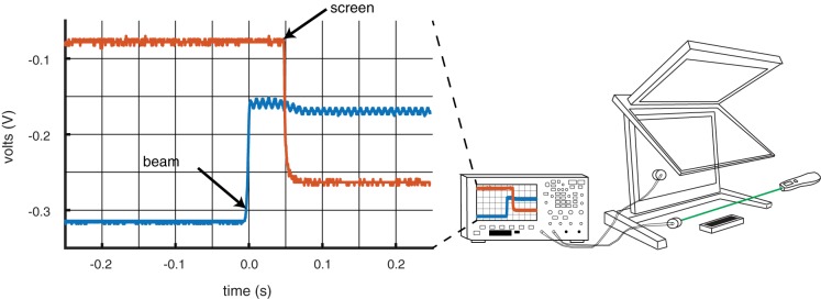
A schematic of the setup is shown in Fig. A3, right. The basic apparatus was the same as in the original experiment (see general methods). Two photocells (VDT Sensors, Hawthorn, CA) were used. The first photocell was placed against the lower of the two Planar monitors. The second photocell was placed opposite a beam of light generated by a laser pointer (green). The Leap controller was placed underneath the beam. Subjects were given the occluder (small flat piece of plastic attached to a ring) to wear on their pointer finger to block the beam of light. Both photocells were connected to an oscilloscope (Agilent DSO-X 2014A; Agilent Technologies, Santa Clara, CA).
Procedure.
Just before each trial, subjects arranged their hand so that the occluder was about to block the beam of light. Once a trial began, any position farther than a threshold of 2 mm forward from the initial position triggered the screen to flip from black to white. The subjects would then move their hand forward, blocking the light beam. The oscilloscope was then used to measure the difference between the onset of motion in physical space (or when the beam of light was blocked) vs. the onset of motion on the screen (or when the screen flipped from black to white). Oscilloscope traces from a sample trial are shown in Fig. A3, left, with the beam photocell in blue and the screen photocell in red. The measurement taken each trial was the difference between the location in time (s) of the step down of the screen photocell and the step up of the beam photocell. Two subjects (S1 and S2 from before) performed 10 trials for each device. When S1 was using the Leap Motion controller as a subject, S2 was the experimenter, taking measurements from the oscilloscope, and vice versa. For comparison, we used exactly the same procedure to evaluate a Bluetooth trackpad (Apple Magic Wireless Trackpad) and a more standard USB mouse (Logitech).
Results.
Figure A4 shows the results for all three devices. Results were consistent across both subjects. The USB mouse was the fastest from motion to screen change at 31 and 34 ms for S1 and S2, followed by the Leap Motion controller at 56 and 66 ms, and finally the Bluetooth trackpad at 102 and 92 ms, respectively. Although the Leap Motion was not the fastest input device, it was clearly within the latency range of common input devices.
Leap Motion Controller Refresh Rate
Leap Motion reports that the device has a refresh rate of 115 Hz. Each sample collected from the leap has a unique ID, so this can be tested. We wrote a Matlab script that sampled from the Leap controller counting the unique frames. We ran this script 10 times for 5 s each. The Leap Motion controller’s update rate was 114 Hz in each of these tests.
Fig. A1.
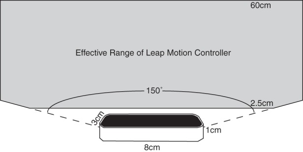
Leap Motion controller. At the bottom is a line drawing of a Leap Motion controller. The controller is 8 cm × 1 cm × 3 cm. Its effective range (colored in gray) is a conical frustrum above the controller.
Fig. A2.
Measurement of drift of stationary fingers and a fixed wooden dowel. Each panel shows the x (blue), y (red), and z (black) drift in position over time during 5-s period in which either the subject (S1, S2) was instructed to remain stationary, or the dowel was fixed above the Leap Motion controller. Clearly, the intrinsic spatial noise level of the Leap Motion controller is much smaller than the steadiness of the observers’ hands.
Fig. A3.
Schematic of photocell arrangement and oscilloscope readings. Right: the first photo-cell was placed on the lower planar monitor. The second was placed to one side of the Leap Motion controller with a beam from a laser pointer pointed directly at the collector. A forward hand movement broke the laser beam and, via the Leap, also triggered the software to flip the screen from black to white. Left: sample oscilloscope output from a single trial. The oscilloscope reports the voltage over time from the screen photocell (red) and the beam photocell (blue). When the subject moves his/her finger forward, the occluder worn on the subject’s finger blocks the laser pointer. This causes the blue trace to step up, and the movement triggers the code to change the screen from black to white, causing the red trace to step down. The time difference between these two steps is the measurement of interest.
Fig. A4.
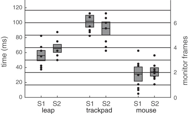
Lag and precision of Leap Motion controller, Bluetooth trackpad, and USB mouse. We measured the lag and temporal precision of 3 devices (Leap, trackpad, and mouse) for two subjects (S1 and S2). The plot shows that temporal lag (milliseconds on the left, frames on the right) for the mean (horizontal line) as well as each trial (black dot). There are 10 trials per condition per subject, but some data points are overlapping. The mean is denoted by the thick black horizontal line, and the standard deviation by the gray box.
REFERENCES
- Allen B, Haun AM, Hanley T, Green CS, Rokers B. Optimal combination of the binocular cues to 3D motion. Invest Ophthalmol Vis Sci 56: 7589–7596, 2015. doi: 10.1167/iovs.15-17696. [DOI] [PubMed] [Google Scholar]
- Badcock DR, Schor CM. Depth-increment detection function for individual spatial channels. J Opt Soc Am A 2: 1211–1216, 1985. doi: 10.1364/JOSAA.2.001211. [DOI] [PubMed] [Google Scholar]
- Baddeley RJ, Ingram HA, Miall RC. System identification applied to a visuomotor task: near-optimal human performance in a noisy changing task. J Neurosci 23: 3066–3075, 2003. [DOI] [PMC free article] [PubMed] [Google Scholar]
- Bonnen K, Burge J, Yates J, Pillow J, Cormack LK. Continuous psychophysics: target-tracking to measure visual sensitivity. J Vis 15: 14, 2015. doi: 10.1167/15.3.14. [DOI] [PMC free article] [PubMed] [Google Scholar]
- Braddick O. A short-range process in apparent motion. Vision Res 14: 519–527, 1974. doi: 10.1016/0042-6989(74)90041-8. [DOI] [PubMed] [Google Scholar]
- Brainard DH. The psychophysics toolbox. Spat Vis 10: 433–436, 1997. doi: 10.1163/156856897X00357. [DOI] [PubMed] [Google Scholar]
- Bredfeldt CE, Ringach DL. Dynamics of spatial frequency tuning in macaque V1. J Neurosci 22: 1976–1984, 2002. [DOI] [PMC free article] [PubMed] [Google Scholar]
- Brooks KR, Stone LS. Stereomotion suppression and the perception of speed: accuracy and precision as a function of 3D trajectory. J Vis 6: 1214–1223, 2006. doi: 10.1167/6.11.6. [DOI] [PubMed] [Google Scholar]
- Cooper EA, van Ginkel M, Rokers B. Sensitivity and bias in the discrimination of two-dimensional and three-dimensional motion direction. J Vis 16: 5–11, 2016. doi: 10.1167/16.10.5. [DOI] [PubMed] [Google Scholar]
- Cumming BG, Parker AJ. Binocular mechanisms for detecting motion-in-depth. Vision Res 34: 483–495, 1994. doi: 10.1016/0042-6989(94)90162-7. [DOI] [PubMed] [Google Scholar]
- Czuba TB, Rokers B, Guillet K, Huk AC, Cormack LK. Three-dimensional motion aftereffects reveal distinct direction-selective mechanisms for binocular processing of motion through depth. J Vis 11: 18, 2011. doi: 10.1167/11.10.18. [DOI] [PMC free article] [PubMed] [Google Scholar]
- Geisler WS, Albrecht DG. Bayesian analysis of identification performance in monkey visual cortex: nonlinear mechanisms and stimulus certainty. Vision Res 35: 2723–2730, 1995. doi: 10.1016/0042-6989(95)00029-Y. [DOI] [PubMed] [Google Scholar]
- Hawken MJ, Shapley RM, Grosof DH. Temporal-frequency selectivity in monkey visual cortex. Vis Neurosci 13: 477–492, 1996. doi: 10.1017/S0952523800008154. [DOI] [PubMed] [Google Scholar]
- Julesz B. Foundations of Cyclopean Vision. Chicago, IL: University of Chicago, 1971. [Google Scholar]
- Julesz B, Bosche C. Studies on Visual Texture and Binocular Depth Perception. A Computer Generated Movie Series Containing Monocular and Binocular Movies. Murray Hill, NJ: Bell Telephone Laboratories, 1966. [Google Scholar]
- Julesz B, Payne RA. Differences between monocular and binocular stroboscopic movement perception. Vision Res 8: 433–444, 1968. doi: 10.1016/0042-6989(68)90111-9. [DOI] [PubMed] [Google Scholar]
- Katz LN, Hennig JA, Cormack LK, Huk AC. A distinct mechanism of temporal integration for motion through depth. J Neurosci 35: 10212–10216, 2015. doi: 10.1523/JNEUROSCI.0032-15.2015. [DOI] [PMC free article] [PubMed] [Google Scholar]
- Kelly DH. Theory of flicker and transient responses. II. Counterphase gratings. J Opt Soc Am 61: 632–640, 1971. doi: 10.1364/JOSA.61.000632. [DOI] [PubMed] [Google Scholar]
- Kelly DH. Pattern detection and the two-dimensional fourier transform: flickering checkerboards and chromatic mechanisms. Vision Res 16: 277–287, 1976. doi: 10.1016/0042-6989(76)90111-5. [DOI] [PubMed] [Google Scholar]
- Kleiner M, Brainard D, Pelli D, Ingling A. What’s new in Psychtoolbox-3. Perception 36: 1–16, 2007. [Google Scholar]
- Lu ZL, Sperling G. The functional architecture of human visual motion perception. Vision Res 35: 2697–2722, 1995. doi: 10.1016/0042-6989(95)00025-U. [DOI] [PubMed] [Google Scholar]
- McKee SP, Levi DM, Bowne SF. The imprecision of stereopsis. Vision Res 30: 1763–1779, 1990. doi: 10.1016/0042-6989(90)90158-H. [DOI] [PubMed] [Google Scholar]
- Menz MD, Freeman RD. Stereoscopic depth processing in the visual cortex: a coarse-to-fine mechanism. Nat Neurosci 6: 59–65, 2003. doi: 10.1038/nn986. [DOI] [PubMed] [Google Scholar]
- Mulligan JB, Stevenson SB, Cormack LK. Reflexive and voluntary control of smooth eye movements. Proc SPIE Int Soc Opt Eng 8651: 86510Z, 2013. doi: 10.1117/12.2010333. [DOI] [Google Scholar]
- Neri P. Coarse to fine dynamics of monocular and binocular processing in human pattern vision. Proc Natl Acad Sci USA 108: 10726–10731, 2011. doi: 10.1073/pnas.1101246108. [DOI] [PMC free article] [PubMed] [Google Scholar]
- Newsome WT, Paré EB. A selective impairment of motion perception following lesions of the middle temporal visual area (MT). J Neurosci 8: 2201–2211, 1988. [DOI] [PMC free article] [PubMed] [Google Scholar]
- Nienborg H, Bridge H, Parker AJ, Cumming BG. Neuronal computation of disparity in V1 limits temporal resolution for detecting disparity modulation. J Neurosci 25: 10207–10219, 2005. doi: 10.1523/JNEUROSCI.2342-05.2005. [DOI] [PMC free article] [PubMed] [Google Scholar]
- Norcia AM, Sutter EE, Tyler CW. Electrophysiological evidence for the existence of coarse and fine disparity mechanisms in human. Vision Res 25: 1603–1611, 1985. [DOI] [PubMed] [Google Scholar]
- Norcia AM, Tyler CW. Temporal frequency limits for stereoscopic apparent motion processes. Vision Res 24: 395–401, 1984. doi: 10.1016/0042-6989(84)90037-3. [DOI] [PubMed] [Google Scholar]
- Ohzawa I. Mechanisms of stereoscopic vision: the disparity energy model. Curr Opin Neurobiol 8: 509–515, 1998. doi: 10.1016/S0959-4388(98)80039-1. [DOI] [PubMed] [Google Scholar]
- Pelli DG. The VideoToolbox software for visual psychophysics: transforming numbers into movies. Spat Vis 10: 437–442, 1997. doi: 10.1163/156856897X00366. [DOI] [PubMed] [Google Scholar]
- Regan D, Beverley KI. The dissociation of sideways movements from movements in depth: psychophysics. Vision Res 13: 2403–2415, 1973a. doi: 10.1016/0042-6989(73)90238-1. [DOI] [PubMed] [Google Scholar]
- Regan D, Beverley KI. Some dynamic features of depth perception. Vision Res 13: 2369–2379, 1973b. doi: 10.1016/0042-6989(73)90236-8. [DOI] [PubMed] [Google Scholar]
- Regan D, Beverley KI. Binocular and monocular stimuli for motion in depth: changing-disparity and changing-size feed the same motion-in-depth stage. Vision Res 19: 1331–1342, 1979. doi: 10.1016/0042-6989(79)90205-0. [DOI] [PubMed] [Google Scholar]
- Ringach DL, Hawken MJ, Shapley R. Dynamics of orientation tuning in macaque V1: the role of global and tuned suppression. J Neurophysiol 90: 342–352, 2003. doi: 10.1152/jn.01018.2002. [DOI] [PubMed] [Google Scholar]
- Rokers B, Cormack LK, Huk AC. Disparity- and velocity-based signals for three-dimensional motion perception in human MT+. Nat Neurosci 12: 1050–1055, 2009. doi: 10.1038/nn.2343. [DOI] [PubMed] [Google Scholar]
- Samonds JM, Potetz BR, Lee TS. Cooperative and competitive interactions facilitate stereo computations in macaque primary visual cortex. J Neurosci 29: 15780–15795, 2009. doi: 10.1523/JNEUROSCI.2305-09.2009. [DOI] [PMC free article] [PubMed] [Google Scholar]
- Shadlen MN, Newsome WT. Neural basis of a perceptual decision in the parietal cortex (area LIP) of the rhesus monkey. J Neurophysiol 86: 1916–1936, 2001. [DOI] [PubMed] [Google Scholar]
- Tyler CW. Stereoscopic depth movement: two eyes less sensitive than one. Science 174: 958–961, 1971. doi: 10.1126/science.174.4012.958. [DOI] [PubMed] [Google Scholar]
- Walsh G, Charman WN. Visual sensitivity to temporal change in focus and its relevance to the accommodation response. Vision Res 28: 1207–1221, 1988. doi: 10.1016/0042-6989(88)90037-5. [DOI] [PubMed] [Google Scholar]
- Wang B, Ciuffreda KJ. Depth-of-focus of the human eye: theory and clinical implications. Surv Ophthalmol 51: 75–85, 2006. doi: 10.1016/j.survophthal.2005.11.003. [DOI] [PubMed] [Google Scholar]
- Wheatstone C. Contributions to the physiology of vision. 1. On some remarkable, and hitherto unobserved, phenomena of binocular vision. Philos Trans R Soc Lond 128: 371–394, 1838. doi: 10.1098/rstl.1838.0019. [DOI] [Google Scholar]
- Williams PE, Mechler F, Gordon J, Shapley R, Hawken MJ. Entrainment to video displays in primary visual cortex of macaque and humans. J Neurosci 24: 8278–8288, 2004. doi: 10.1523/JNEUROSCI.2716-04.2004. [DOI] [PMC free article] [PubMed] [Google Scholar]


