

Abstract
Reflectance Confocal Microscopy, or RCM, is being increasingly used to guide diagnosis of skin lesions. The combination of widefield dermoscopy (WFD) with RCM is highly sensitive (~90%) and specific (~ 90%) for noninvasively detecting melanocytic and non-melanocytic skin lesions. The combined WFD and RCM approach is being implemented on patients to triage lesions into benign (with no biopsy) versus suspicious (followed by biopsy and pathology). Currently, however, WFD and RCM imaging are performed with separate instruments, while using an adhesive ring attached to the skin to sequentially image the same region and co-register the images. The latest small handheld RCM instruments offer no provision yet for a co-registered wide-field image. This paper describes an innovative solution that integrates an ultra-miniature dermoscopy camera into the RCM objective lens, providing simultaneous wide-field color images of the skin surface and RCM images of the subsurface cellular structure. The objective lens (0.9 NA) includes a hyperhemisphere lens and an ultra-miniature CMOS color camera, commanding a 4 mm wide dermoscopy view of the skin surface. The camera obscures the central portion of the aperture of the objective lens, but the resulting annular aperture provides excellent RCM optical sectioning and resolution. Preliminary testing on healthy volunteers showed the feasibility of combined WFD and RCM imaging to concurrently show the skin surface in wide-field and the underlying microscopic cellular-level detail. The paper describes this unique integrated dermoscopic WFD/RCM lens, and shows representative images. The potential for dermoscopy-guided RCM for skin cancer diagnosis is discussed.
Keywords: Reflectance Confocal Microscopy, Dermoscopy
1. INTRODUCTION
Real-time confocal microscopy of intact skin offers the clinician the possibility of noninvasive examination of large areas of tissue, compared to invasive biopsy, and may eventually obviate biopsies of many benign lesions. But the limited field of view during confocal microscopy and the lack of landmarks to relate microscopic tissue structure to the gross morphology of the lesion presents a practical challenge. For this reason, some of the original clinical reflectance confocal microscopy (RCM) systems include a separate wide-field dermoscopy (WFD) camera to provide a reference image, and then attempt to register the subsequent confocal images to the wide-field dermoscopy view using a mechanical means such as an adhesive ring attached to the skin.1 Some recent results have shown the promise of RCM+WFD to reduce the need for biopsy of benign lesions, by two times, compared to that with dermoscopy alone2–5 (which is the current standard in the clinic). During the past 2–3 years, the implementation of WFD and RCM imaging to guide noninvasive diagnosis (to rule out malignancy and biopsy), by early adopter clinicians in about seven academic settings, has shown promising initial impact: about 3,000 patients have been spared biopsies of their benign lesions2,6–9 (and these are being monitored with follow up imaging).
Some newer handheld RCM instruments have no dermoscopy capability, instead relying on the skill of the clinician to maneuver the instrument relative to the lesion, using only microscopic cues for guidance. Without the benefit of adhesive rings or other mechanical means, the registration between WFD and RCM images is an entirely manual, subjective and uncontrolled approach. This can result in increased variability when combining dermoscopic and RCM findings and increased uncertainty in reading the images together to guide diagnosis.
In this paper, we describe an approach that integrates a wide-field dermoscopy camera directly into the objective lens used for RCM, so that simultaneous RCM and WFD views are available to the clinician using a handheld imaging probe. We first describe the concept for a handheld instrument with both WFD and RCM. Then we describe a benchtop instrument we developed to investigate the capability and limitations of the approach for future clinical implementations. Imaging examples obtained from healthy volunteers illustrate the viability of producing high quality RCM of subsurface cellular structure with automatically registered real-time concurrent WFD showing the location and gross morphology of the surrounding skin surface.
2. DUAL-VIEW OPTICS USING AN ANNULAR PUPIL FOR MICROSCOPY
2.1 Handheld Instrument Concept
Our instrument concept is illustrated in Figure 1. A compact optical system is based on fiber delivery of laser light and built-in 2D beam scanning for RCM. The objective lens is designed around an aplanatic hyperhemisphere frontpiece with sufficient space between the hyperhemisphere lens and the next optic to insert a miniature CMOS camera. By using an annular beam, the central part of the lens is available to mount the miniature camera without affecting the confocal image. The color CMOS WFD camera includes a wide-field imaging lens to view the full contact area between the hyperhemisphere lens and the skin. White-light LEDs illuminate the skin surface for WFD. With this approach, the WFD image is real-time during RCM, and the region undergoing RCM is visible in the dermoscopy view. Furthermore, the camera can image the skin surface as the instrument approaches, allowing easy placement of the probe in the context of skin surface features.
Figure 1.

Concept for a handheld dual-view microscope providing wide-field dermoscopy with simultaneous reflectance confocal microscopy. The final optic in the tip of the instrument, in contact with the skin, is a glass hyperhemisphere that focuses a high-NA annular beam for RCM, and also supports a miniature wide-field color camera and LED illumination system for dermoscopy.
2.2 Benchtop System Developed to Investigate Capabilities and Limitations
We designed a benchtop system to investigate the possibilities of a dual-view instrument based on integrating a miniature camera into the objective lens. The video-rate RCM platform that has been described previously10 includes a fast-scan polygon scanner and a slow-scan galvo, with 4f relays between the scanners and between the second scanner and the back aperture of the objective lens. The light source is a diode laser at λ=648 nm. The detector is an avalanche photodiode behind a pinhole with a normalized diameter ~5.2 times the diameter of the first Airy null. A compound objective lens comprises a long working distance 20× 0.4 NA lens (Huvitz LPlanFluor 20X, WD=12.2mm) behind a 6 mm diameter BK7 hyperhemisphere that is 4.85 mm thick. The hyperhemisphere increases the NA by the square of the index of refraction of the glass, which for BK7 at 648 nm is n = 1.51, bringing the maximum effective NA of the compound lens to 0.4*1.512 ≈ 0.9 NA. Adjustment of the depth of the focal plane in the tissue for RCM is achieved by adjusting the distance between the 20× lens and the hyperhemisphere. This compound lens leaves an air space of approximately 4.35 mm between the 20× lens and the hyperhemisphere frontpiece, which is sufficient to accommodate our miniature WFD camera assembly.
The camera forms a central obscuration, resulting in an annular pupil for the confocal beam. To verify that we still retain usefully sharp optical sectioning with the annular pupil we measured the signal return V(z) at the photodetector from a plane mirror swept through focus, with a gel immersion medium approximating the index of refraction of epidermis. A representative result is shown in Figure 3. We measure an axial V(z) response with zFWHM = 3.8μm with a clear aperture (no WFD camera), compared to zFWHM = 3.7 3m with a central obscuration of 1.2 mm at the hyperhemisphere. The measurement is made at a depth of approximately 75 μm from the glass surface, near where spherical aberration is balanced. The axial response degrades slowly at depths on either side of the optimal range.
Figure 3.

Axial response V(z) to a plane reflector scanned through the focal plane for the compound lens illustrated in Figure 2. (a) with a clear (circular) pupil; (b) with the obscured (annular) pupil corresponding to the presence of the WFD camera.
3. DETAILS OF THE DERMOSCOPY CAMERA
The camera for WFD is diagrammed in Figure 4. The sensor is a miniature CMOS imager called Naneye, manufactured by Awaiba, GMBH (now CMOSIS). The packaged sensor measures approximately 1.1 mm square, with an active area of 0.75 mm comprising 250 × 250 square pixels on a 3.0 μm pitch, overlayed with a Bayer pattern color filter. A 400 μm thick coverglass of Corning Eagle XG borosilicate glass protects the sensor, which is provided without any lens or aperture. A serial electronic readout is supported via a four conductor miniature ribbon cable that measures 0.72 × 0.19 mm in cross section. We designed an F/5 camera lens with magnification 0.2x, using a 1 mm diameter hemisphere lens of sapphire. The sapphire hemisphere is aligned and glued to the aperture block, which is a 0.5 mm thick fused silica plate coated with an opaque aluminum layer patterned with a 150 μm diameter circular aperture. The aperture block is aligned and cemented in place on the apex of the 6 mm diameter hyperhemisphere using optical UV epoxy. The spacing between the aperture block and the cover on the CMOS sensor is set by a length of hypodermic steel tubing with 1 mm inside diameter that fits around the hemisphere lens and prevents stray light from striking the sensor. The objective lens components are shown in Figure 5(A). The fully assembled WFD camera on the BK7 hyperhemisphere is shown in Figure 5(B). An aluminum mount holds the hyperhemisphere, and also supports the flexible printed circuit with the illumination LEDS.
Figure 4.
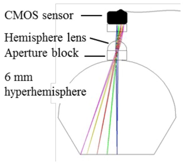
WFD camera. Details are provided in the text.
Figure 5.

WFD camera components. A) prior to assembly, the hemisphere lens, aligned and glued to the aperture block, is shown on the left, with a hypodermic tube spacer in the center and the Naneye CMOS sensor on the right. The scale at the top of the image has tic marks at 1 mm intervals; B) after alignment and attachment to the BK7 hyperhemisphere front piece. The hyperhemisphere is supported in an aluminum mount. Also visible in the image are the arms of the flexible printed circuit that supports the illumination LEDs.
The optical system was characterized using a back-illuminated transparent 1951 USAF target placed in contact with the flat surface of the hyperhemisphere, as shown in Figure 6(A). We estimated sinusoidal modulation transfer function (MTF) values from the normalized FFT spectra of the measured 3 bar targets, following the method of Boreman11. We used the sum of the red, green and blue (RGB) signals for the computation. The results are plotted in Figure 6(B). Fifty percent modulation depth is observed for spatial frequencies of approximately 14 lp/mm, corresponding to bar and space widths of 36 μm. The field of view at the sample is 3.8 mm horizontally and vertically, and 5.4 mm along the diagonal. The diameter of the glass interface where the hyperhemisphere contacts the skin is 4.7 mm, which sets the useable field of view of the WFD camera during imaging.
Figure 6.

(A) Sample image of 1951 USAF target; (B) Measured MTF response for the WFD camera.
4. PRELIMINARY IMAGING RESULTS: WFD + RCM OF HEALTHY SKIN
The benchtop system was used to image the skin (pigmented lesions on forearms) of 15 volunteers, who were recruited under an approved IRB protocol in the Dermatology Service at Memorial Sloan Kettering Cancer Center (MSKCC). WFD images were used to guide the position for subsurface RCM imaging. Because the laser wavelength used is within the passband of the WFD sensor, we could easily see the scanning laser on the skin surface. An attenuator on the laser made it possible to reduce the beam power during WFD imaging to prevent saturation of the CMOS sensor.
5. DISCUSSION AND CONCLUSIONS
Based on our initial imaging on several volunteers, we find that the concept of a miniature WFD camera integrated into a high NA objective lens is very promising. Our clinicians who observed the real-time imaging sessions were enthusiastic about the potential for real-time registration of the RCM field of view within the dermoscopic image of the skin. The performance of RCM using the annular aperture was consistent, retaining good sectioning ability and clearly resolving cellular features. A more complete characterization of the RCM optical performance and its dependence on the specifics of the central obscuration will be forthcoming.
The images generated by the WFD camera were sufficient for guiding RCM and registering RCM images. They are not of diagnostic quality for use as a stand-alone dermoscopy camera, limited primarily by the low 250×250 pixel count of the miniature sensor. Currently the MTF of the WFD camera is limited by the effective pixel size of the color camera, rather than the lens system. The resolution could be effectively doubled by using a monochrome sensor without the Bayer color filter, and using RGB LEDs for sequential tri-color illumination. This is an improvement that may be investigated in the future. But without increasing the sensor footprint it will not be feasible to dramatically increase the pixel count in the images. The current pixel pitch of 3 μm is already small for today’s technology; furthermore the simple hemisphere lens will limit the system MTF for pixels much smaller than that. Given the size constraints of a handheld probe, there will be a tradeoff, since increasing the size of the WFD camera in order to increase dermoscopy resolution would also increase the overall size of the instrument. However, to increase the field of view, we may implement mosaicking approaches, similar to those that we have developed for our current RCM instruments12. Further investigations using the benchtop system are expected to help us better understand the clinical value of having concurrent WFD and RCM imaging, and how best to balance the tradeoffs between dermoscopy image quality, RCM image quality and field of view, and the overall instrument size.
Based on these initial results, we are enthusiastic about the possible clinical impact of concurrent WFD and RCM, and the potential for our approach of integrating a WFD camera within the RCM objective lens as a viable and practical way to deliver these concurrent images.
Figure 2.
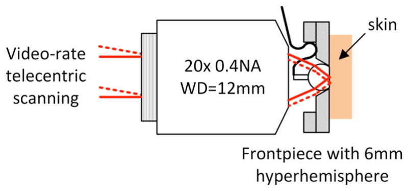
Compound objective lens for the benchtop imaging system. The combination of the 0.4 NA microscope objective with the hyperhemisphere frontpiece results in overall NA=0.9 in the tissue. The space between the microscope objective and the hyperhemisphere accommodates the miniature WFD camera.
Figure 7.

Concurrent WFD and RCM images: (A) WFD of a pigmented nevus on the forearm of a volunteer. (B) Corresponding RCM at the epidermal-dermal junction showing bright basal cells, which typically occur at ~50–100 um depth.
Acknowledgments
This research is supported by the National Institute of Biomedical Imaging and Bioengineering, of the National Institutes of Health, under grant 1R21EB018507. Partial support was also provided by the National Cancer Institute, under MSKCC Support Grant/Core Grant P30CA008748.
References
- 1.Rajadhyaksha M, González S, Zavislan JM, Anderson RR, Webb RH. In vivo confocal scanning laser microscopy of human skin II: advances in instrumentation and comparison to histology. Journal of Investigative Dermatology. 1999;113:293–303. doi: 10.1046/j.1523-1747.1999.00690.x. [DOI] [PubMed] [Google Scholar]
- 2.Alarcon I, Carrera C, Palou J, Alos L, Malvehy J, Puig S. Impact of in vivo reflectance confocal microscopy on the number needed to treat melanoma in doubtful lesions. British Journal of Dermatology. 2014;170(4):802–808. doi: 10.1111/bjd.12678. [DOI] [PMC free article] [PubMed] [Google Scholar]
- 3.Pellacani G, Pepe P, Casari A, Longo C. Reflectance confocal microscopy as a second-level examination in skin oncology improves diagnostic accuracy and saves unnecessary excisions: a longitudinal prospective study. British Journal of Dermatology. 2014;171:1044–1051. doi: 10.1111/bjd.13148. [DOI] [PubMed] [Google Scholar]
- 4.Ferrari B, Pupelli G, Farnetani F, De Carvalho NT, Longo C, Reggiani C, Argenziano G, Pellacani G. Dermoscopic difficult lesions: an objective evaluation of reflectance confocal microscopy impact for accurate diagnosis. J Eur Acad Dermatol Venereol. 2015;29(6):1135–40. doi: 10.1111/jdv.12769. [DOI] [PubMed] [Google Scholar]
- 5.Lovatto L, Carrera C, Salerni G, Alós L, Malvehy J, Puig S. In vivo reflectance confocal microscopy of equivocal melanocytic lesions detected by digital dermoscopy follow-up. J Eur Acad Dermatol Venereol. 2015;29(10):1918–25. doi: 10.1111/jdv.13067. [DOI] [PubMed] [Google Scholar]
- 6.Ahlgrimm-Siess V, Hofmann-Wellenhof R, Cao T, Oliviero M, Scope A, Rabinovitz HS. Reflectance Confocal Microscopy In The Daily Practice. Seminars in Cutaneous Medicine and Surgery. 2009;28(3):180–9. doi: 10.1016/j.sder.2009.06.008. [DOI] [PubMed] [Google Scholar]
- 7.Ulrich M, Lance-Asschenfeldt S. The Use of Reflectance Confocal Microscopy for Monitoring Response to Therapy of Skin Malignancies. Dermatology Practical & Conceptual. 2012;2(2):10, 43–52. doi: 10.5826/dpc.0202a10. [DOI] [PMC free article] [PubMed] [Google Scholar]
- 8.Guitera P, Moloney FJ, Menzies SW, Stretch J, Quinn MJ, Hong A, Fogarty G, Scolyer RA. Improving management and patient care of lentigo maligna by mapping with in vivo confocal microscopy. JAMA Dermatology. 2013;149(6):692–8. doi: 10.1001/jamadermatol.2013.2301. [DOI] [PubMed] [Google Scholar]
- 9.Giambrone D, Alamgir M, Masud A, Bronsnick T, Rao B. The diagnostic accuracy of in vivo confocal microscopy in clinical practice. J Am Acad Dermatol. 2015;73(2):317–9. doi: 10.1016/j.jaad.2015.03.052. [DOI] [PubMed] [Google Scholar]
- 10.Rajadhyaksha M, Anderson RR, Webb RH. Video-rate confocal scanning laser microscope for imaging human tissues in vivo. Applied Optics. 1999;38:2105–2115. doi: 10.1364/ao.38.002105. [DOI] [PubMed] [Google Scholar]
- 11.Boreman G, Yang S. Modulation transfer function measurement using three-and four-bar targets. Applied optics. 1995;34(34):8050–8052. doi: 10.1364/AO.34.008050. [DOI] [PubMed] [Google Scholar]
- 12.Kose K, Cordova M, Duffy M, Flores ES, Brooks DH, Rajadhyaksha M. Video-mosaicing of reflectance confocal images for examination of extended areas of skin in vivo. British J Dermatology. 2014;171:1239–1241. doi: 10.1111/bjd.13050. [DOI] [PMC free article] [PubMed] [Google Scholar]