Abstract
The primary focus of this work is to present the current challenges of printing scaffolds with concentration gradients of nanoparticles with an aim to improve the processing of these scaffolds. Furthermore, we address how print fidelity is related to material composition and emphasize the importance of considering this relationship when developing complex scaffolds for bone implants. The ability to create complex tissues is becoming increasingly relevant in the tissue engineering community. For bone tissue engineering applications, this work demonstrates the ability to use extrusion-based printing techniques to control the spatial deposition of hydroxyapatite (HA) nanoparticles in a 3D composite scaffold. In doing so, we combined the benefits of synthetic, degradable polymers, such as poly(propylene fumarate) (PPF), with osteoconductive HA nanoparticles that provide robust compressive mechanical properties. Furthermore, the final 3D printed scaffolds consisted of well-defined layers with interconnected pores, two critical features for a successful bone implant. To demonstrate a controlled gradient of HA, thermogravimetric analysis was carried out to quantify HA on a per-layer basis. Moreover, we non-destructively evaluated the tendency of HA particles to aggregate within PPF using micro-computed tomography (µCT). This work provides insight for proper fabrication and characterization of composite scaffolds containing particle gradients and has broad applicability for future efforts in fabricating complex scaffolds for tissue engineering applications.
Keywords: viscosity, composites, compressive modulus, bone tissue engineering, gradient
Introduction
Bone is a complex tissue comprised of both compositional and structural gradients [1]. Recent work in the tissue engineering community has sought to recapitulate the complexities of the osteochondral interface by fabricating scaffolds with gradients of extracellular matrix (ECM) [2], bioactive molecules [3], and pore size gradients [4, 5]. Biologically, calcium phosphate concentrations gradually increase from the uncalcified region of cartilage to underlying region of subchondral bone [1]. Specifically for the subchondral bone, polymer scaffolds with a compositional gradient of ceramic nanoparticles are interesting from both a mechanical and bioactivity standpoint. It remains to be proven the optimal composition needed in a synthetic scaffold to promote functional bone regeneration. However, it is commonly known that nanoparticles have a greater surface area to volume ratio than microparticles, providing better mechanical reinforcement in a composite. Additionally, hydroxyapatite (HA) nanoparticles have been shown to improve bone tissue formation and have more biological relevance than HA microparticles [6–8].
There are, however, inherent challenges associated with the fabrication and characterization of compositional gradients. The uniform mixing of polymer and ceramic composites is known to be challenging, often due to opposing physical and chemical interactions. Additionally, when working with nanoparticles, it is often difficult to achieve uniform particle dispersion and prevent particle aggregation, which can diminish the effectiveness of the nanoparticles to improve composite mechanical properties [9]. Many strategies have been employed to understand and improve the interfacial interactions of polymers and ceramics [10–12], including the incorporation of surfactants, modification of surface chemistry, and application of magnetic fields. Yet, for the purposes of tissue engineering, it is important to use approaches that are simple, are clinically relevant, and minimize cytotoxicity. Furthermore, few investigations have evaluated the effects of composition on the fabrication of gradients, specifically the rheological properties and how those affect scaffold architecture. In order to successfully incorporate compositional gradients, material properties and composite interactions should be considered during the fabrication of fibrous scaffolds.
From a materials standpoint, poly(propylene fumarate) (PPF) has been used previously as a bone implant material [13, 14]. In recent work, PPF was a successful candidate for extrusion-based printing [15]. The in vitro osteogenic potential has been characterized by both PPF-HA scaffolds fabricated by salt leaching [16] and PPF scaffolds fabricated by stereolithography (STL) [17]. HA improved cell-material interactions and osteogenic gene expression in vitro [16], underlining the osteoconductive properties of HA. Additionally, STL scaffolds with interconnected pores promoted enhanced osteogenic gene expression as compared to salt leached scaffolds [17], demonstrating that scaffolds prepared by additive manufacturing methods promote bone tissue formation due to improved mass transport.
Extrusion-based 3D printing, in particular, allows for direct fabrication of scaffolds with interconnected pores and pore sizes relevant for bone tissue engineering [15, 18]. Compared to STL techniques that typically allow only single-material printing, extrusion-based printing systems allow printing of multiple materials simultaneously, which facilitates the fabrication of scaffolds with compositional gradients. Recent work provides a detailed comparison of STL and extrusion-based printing, including limitations in print resolution [19]. A few reports have explored extrusion-based printing of scaffolds with multiple material compositions [20–24], but the printing behavior of each material and the effect of graded composition on printing uniformity have not been characterized extensively. Due to the scarce material analysis available for multi-material printing, we systematically characterized extrusion-based printing of PPF scaffolds with HA nanoparticle gradients, which better mimic the native tissue environment in bone.
Once a gradient is fabricated, it is often difficult to effectively characterize its spatial properties within the scaffold. Specifically, the ability to quantitatively and qualitatively evaluate the dispersion of particles and prove the presence of a gradient can be a challenge when working with nanoparticles. Micro-computed tomography (µCT) is a non-destructive technique that provides a full 3D reconstruction of the scaffold and gives a better summary of particle distribution and aggregation [25, 26] than techniques that primarily characterize the surface, such as atomic force microscopy (AFM) [27] or Fourier transform-infrared spectroscopy (FT-IR) [28]. This can also be coupled with quantitative techniques like thermogravimetric analysis (TGA) to quantify concentrations within scaffold layers or within cross-sections to prove the presence of a gradient or a uniform particle distribution.
The aim of this work is to generate biologically relevant scaffolds with defined and controlled compositional gradients, robust mechanical properties, and interconnected pores to facilitate mass transport in vitro and in vivo for bone tissue applications. We first investigated if addition of a surfactant improved HA particle dispersion using µCT. Then, we investigated the effect of the surfactant on scaffold properties, including printing solution viscosity, fiber diameter, porosity, pore size and interconnectivity, and compressive mechanical properties. We then demonstrated the ability to fabricate scaffolds with a HA gradient, evaluated the nanoparticle distribution, and quantitatively evaluated the HA concentration within each layer of the scaffold.
Materials and methods
Synthesis and characterization of PPF
PPF was synthesized as previously described using a two-step condensation reaction [29]. The number average molecular weight (Mn) and polydispersity index (PDI) were characterized by gel permeation chromatography in triplicate following previous methods [15]. Mn and PDI were, respectively, 2980 ± 30 Da and 2.06 ± 0.01 for the surfactant study and 2280 ± 20 Da and 1.72 ± 0.02 for the bilayer and gradient study.
Polymer/ceramic composite preparation
Synthesized PPF (Mn 2000–3000 Da) was mixed with a solution of diethyl fumarate (DEF, Sigma, St. Louis, MO) – used to reduce the viscosity of the printing solution – and phenylbis(2,4,6-trimethylbenzoyl)-phosphine oxide (BAPO, BASF, Florham Park, NJ), used as a photoinitiator for polymer crosslinking. For scaffolds containing surfactant, a 0.1 M solution of sodium dodecyl sulfate (SDS, Sigma, St. Louis, MO) in dimethyl sulfoxide (DMSO ACS reagent, Sigma, St. Louis, MO) (0.144 g SDS in 5 mL DMSO) was prepared and mixed with HA (<200 nm particle size, Sigma-Aldrich, St. Louis, MO) (120 µL per 1 g HA) prior to ultrasonication. SDS surfactant was added to improve HA nanoparticle dispersion. HA was ultrasonicated with or without surfactant for 2 min before being mixed into the PPF:DEF:BAPO solution. Solutions were prepared following Table 1 and loaded into a 30 mL plastic syringe barrel (Optimum® Syringe barrel; Nordson EFD; East Providence, RI) with a high viscosity piston (SmoothFlow™ piston; Nordson EFD; East Providence, RI) and a 0.840 mm (inner diameter, 18 gauge) plastic tapered syringe tip (Dispense tips; Nordson EFD; East Providence, RI). For the bilayer and gradient scaffolds, solutions were prepared following Table 2. More BAPO was added to solutions containing HA due to their optical properties, as they tend to disperse UV light and diminish crosslinking [30, 31].
Table 1.
Preparation of PPF-HA printing solutions with and without surfactant*
| PPF:DEF | mPPF (g) | VDEF (mL) | DMSO/SDS (mL) | HA (g) (10 wt%) |
BAPO (mg) (2 wt%) |
|---|---|---|---|---|---|
| 85:15 | 10 | 1.512 | 0.157 | 1.3072 | 240 |
| 85:15 | 10 | 1.669 | - | 1.3072 | 240 |
Considering PPF density (Mn2530) ρPPF = 1.27 g/cm3 [35], and DEF density (Mn 172) ρDEF = 1.05 g/cm3 (Sigma Aldrich) at 25 °C. mPPF = PPF mass, VDEF = DEF volume, wt% reported as
Table 2.
Preparation of PPF-HA printing solutions for bilayer and gradient scaffolds*
| mPPF (g) | VDEF (mL) | HA | BAPO | ||
|---|---|---|---|---|---|
| (g) | (wt%) | (mg) | (wt%) | ||
| 10 | 1.677 | 0 | 0 | 118.8 | 1 |
| 10 | 1.677 | 0.1489 | 1.25 | 240.1 | 2 |
| 10 | 1.677 | 0.3017 | 2.5 | 240.1 | 2 |
| 10 | 1.677 | 0.6192 | 5 | 240.1 | 2 |
| 10 | 1.677 | 1.3072 | 10 | 240.1 | 2 |
Considering PPF density (Mn 2530) ρPPF = 1.27 g/cm3 [35], and DEF density (Mn 172) ρDEF = 1.05 g/cm3 (Sigma Aldrich) at 25°C. mPPF= PPF mass, VDEF= DEF volume, wt% reported as
Scaffold printing
All scaffolds were fabricated using a commercial 3D printing system (3D Bioplotter, EnvisionTEC, Gladbeck, Germany) capable of printing multiple materials at a wide range of temperatures (2 – 250 °C) and pressures (0 – 9 bar). PPF and PPF-HA solutions were loaded into separate print heads and were heated to their respective temperatures (Table 3) for 30 min prior to printing. After printing one layer, a UV curing head was used to crosslink the layer for a specified duration (Table S1). The printer took successive images of each layer during printing, allowing quantification of pore size and fiber diameter in each layer (described in Scaffold Characterization). The center-to-center spacing between adjacent fibers for all scaffolds was 1.2 mm. Scaffolds were printed concurrently on cardstock with EnvisionTEC software (BioplotterRP, EnvisionTEC, Gladbeck, Germany). Printing settings are specified in Supplemental Information.
Table 3.
3D printing settings for printing PPF-HA gradient scaffolds and printing solution properties*
| Formulation | Temperature, T (°C) |
Pressure, P (bar) |
Print head speed, F (mm/s) |
Layer thickness, z (mm) |
Experimental fiber diameter, d (mm) |
Apparent viscosity, ηa (Pa•s) |
|
|---|---|---|---|---|---|---|---|
| Surfactant | S-HA 10 % with SDS | 65 | 0.8 | 1.5 | 0.5 | 0.752 ± 0.003C | 30.8 ± 0.3A |
| S-HA 10 % without SDS | 65 | 0.8 | 1.5 | 0.5 | 0.682 ± 0.024C | 37.5 ± 2.6B | |
| Bilayer | B-HA 0 % | 50 | 0.3 | 12 | 0.3 | 0.794 ± 0.067B, C | 11.7 ± 2.1C, D |
| B-HA 10 % | 55 | 0.8 | 8 | 0.3 | 0.779 ± 0.093C | 5.5 ± 1.2E | |
| Gradient | G-HA 1.25 % | 55 | 0.4 | 10 | 0.3 | 0.931 ± 0.045A, B | 8.7 ± 0.9D, E |
| G-HA 2.5 % | 55 | 0.5 | 8 | 0.3 | 0.941 ± 0.023A | 8.9 ± 0.4D, E | |
| G-HA 5 % | 55 | 0.5 | 8 | 0.3 | 0.709 ± 0.055C | 15.8 ± 2.5C | |
| G-HA 10 % | 55 | 0.5 | 8 | 0.3 | 0.734 ± 0.015C | 14.6 ± 0.6C |
All other print settings are as follows: Syringe tip inner diameter (ds, 0.840 mm), fiber spacing, (s, 1.2 mm). Refer to Table S1 for the detailed list of print settings. Values marked with the same letter (A–E) do not differ statistically, with A being the highest value (p ≥ 0.05).
For the S-HA 10 % scaffolds with or without SDS, a 10×10 mm square was designed (SolidWorks, Waltham, MA) and sliced into 9 layers (Figure 1a, Figure S1) (0.5 mm slicing thickness) using BioplotterRP. For the bilayer scaffolds, a 10 × 10 mm square composed of 6 layers (0.3 mm slicing thickness) was designed, and layers were printed following the schematic in Figure 1b (also refer to Figure S2). It was necessary to reduce the slicing thickness for bilayer and gradient scaffolds because solutions containing lower concentrations of HA tended to spread during printing. For the gradient scaffolds, each 10 × 10 mm scaffold contained 8 layers (0.3 mm slicing thickness) with 2 layers each of the 4 concentrations (1.25, 2.5, 5, and 10 wt% HA). Scaffolds were printed in ascending and descending concentration (descending schematic in Figure 1c and Figure S3. Two concentrations were loaded into the printer at one time to print the first 4 layers, after which the second set of concentrations was loaded and printed on top of the first two with a vertical offset of 0.4 mm from the top of the 4th layer. In order to fully crosslink the polymer, all scaffolds were post-processed in a flash box (Otoflash, EnvisionTEC, Gladbeck, Germany) following previous methods [15].
Figure 1.
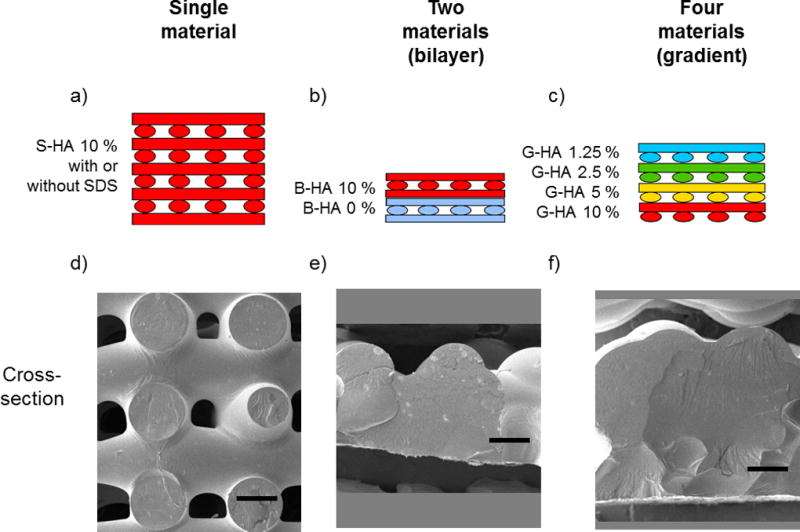
Schematic of printed scaffolds. (a) PPF-HA (10 wt%) scaffold with or without SDS. (b) PPF-HA bilayer scaffold containing PPF and PPF-HA (10 wt%). (c) PPF-HA gradient scaffold containing layers of 1.25, 2.5, 5, and 10 wt% HA. Respective SEM cross-sections of (d) a PPF-HA scaffold with or without SDS, (e) a PPF-HA bilayer scaffold, and (f) a PPF-HA gradient scaffold. Pore interconnectivity is lost with the addition of multiple materials. Scale bars in (d)–(f) represent 0.5 mm. Rotated views of (d)–(f) are presented in their respective supplemental figures, Figures S1–3.
Scaffold characterization
Viscosity of printing solution
Based on previously reported methods [15], the apparent viscosity of the printing solutions (Equation 1) was calculated based on the volume of material extruded over time (i.e. flow rate of a fiber with circular cross-section, Qc). This is a simple method that models the extruder as a capillary die rheometer, allowing real-time testing of the printing solution viscosity while the material is being extruded [32]. A single fiber was extruded (initial fiber diameter test), and the fiber diameter (d) was measured based on previous methods [15] and compared to a power relationship described previously [33]. The pressure drop (ΔP = Patm – Papp = 1.013 bar – Papp) and fiber diameter varied depending on the printing solution (Table 3), while syringe diameter (ds, 0.840 mm) and syringe length (Ls, 12.7 mm) were kept constant. Apparent (Newtonian) shear rate at the wall (γ̇aw) and shear stress at the wall (τw) were used to estimate apparent viscosity.
| Equation 1. Apparent viscosity, capillary die rheometer |
Pore and fiber morphology analysis of PPF-HA scaffolds
Pore size, fiber diameter, and fiber spacing were measured based on previous methods [15]. Briefly, a scale was set based on image dimensions (0.009 mm/pixel, 1032 × 776 pixels), and imaging software (ImageJ, NIH) was used to take measurements (n = 5 measurements each per layer, 4 scaffolds per group – PPF-HA with SDS, PPF-HA without SDS, bilayer, gradient descending). Example pore and fiber measurements are shown in Figures S1a–S3a.
Porosity measurements of PPF-HA scaffolds
Porosity was quantified (n = 5 per formulation) using gravimetric analysis following previous methods [34]. Briefly, sample dimensions (length, L; width, W; thickness, H) and mass (mscaffold) were measured and used to calculate the porosity according to Equation 2, where ρscaffold is the scaffold density and ρmaterial is the density of the material. The respective densities of PPF (1.267 × 10⁻³ g/mm3) [35], DEF (1.052×10⁻³ g/mm3) (Sigma), HA (3.14×10⁻³ g/mm3) (Sigma), SDS (0.370×10⁻³ g/mm3), BAPO (1.19×10⁻³ g/mm3) (BASF), and DMSO (1.10×10⁻³ g/mm3) (Sigma) were used to estimate ρmaterial for each printing solution following quantities in Table 1, Table 2, and layers within each scaffold type.
| Equation 2. Scaffold porosity |
Compressive mechanical testing of S-HA 10 % scaffolds
For scaffold groups S-HA 10 % scaffolds with SDS and PPF-HA without SDS (Table 3), the compressive mechanical properties (n = 10 per formulation) of the composite were evaluated (MTS, 858 Mini Bionix, Eden Prairie, MN) to determine the effect of SDS on compressive modulus. We did not evaluate the compressive mechanical properties of the bilayer and gradient scaffolds due to their lack of pore interconnectivity. 10 mm length × 10 mm width × 2.5 mm height (approximate scaffold thickness) scaffolds were compressed perpendicular to their short axis at a cross-head speed of 0.5 mm/min after an initial pre-load of 25 N, following previous work [34]. The compressive modulus (elastic region between a fixed strain of 0.20–0.30 %, Poisson ratio = 0.5) was calculated using a Python script (see Supplemental Information) [36, 37].
Scanning electron microscopy (SEM)
The surface morphology of the 3D printed scaffolds was imaged using scanning electron microscopy (SEM) to characterize the fiber morphology, roughness, and pore interconnectivity. Samples (n = 1 per formulation) were sputter-coated with 20 nm of gold (Denton Desk V, Moorestown, NJ) and SEM (FEI Quanta 400 ESEM FEG, FEICo, Hillsboro, OR) images were obtained at 2.00 kV (high voltage, HV) with 30 or 50× magnification following previous methods [38].
Micro-computed tomography (µCT) analysis
In order to characterize HA particle dispersion (due to the addition of surfactant and changes in HA concentration in gradient scaffolds), 3D printed scaffolds were scanned using a Skyscan 1172 µCT (Skyscan, Aartsellar, Belgium). Scans were performed with Skyscan 1172 software (v. 1.5) (Bruker, Billerica, MA) at an X-ray voltage of 40 kV and a current of 250 µA. S-HA 10 % images were taken with a step angle of 0.2° and a nominal resolution of 13.52 µm/pixel (no filter). Gradient scaffold images were taken with a step angle of 0.25° and a resolution of 12.49 µm/pixel (no filter). NRecon (v. 1.6.9.18), CTAn (v.1.15.4.0), and CTVox (v.3.0.0) software were used to reconstruct and analyze scans (Bruker, Billerica, MA).
Thermogravimetric analysis (TGA)
Single printed layers containing 0, 1.25, 2.5, 5, or 10 wt% HA in PPF were analyzed via TGA (TGA Q50, TA Instruments; New Castle, DE) to confirm HA content following established methods [39]. Briefly, 20 mg of printed material (n = 3 per formulation) was heated from room temperature to 95 °C at a constant ramping rate of 20 °C/min, equilibrated at 100 °C for 10 min, ramped to 500 °C at 20 °C/min, and equilibrated for 10 min. Oxygen flow rates of the balance and sample were 40 and 60 mL/min, respectively. Results were analyzed with TGA software (TA Universal Analysis; TA Instruments). The normalized sample weight (expressed as a fraction of the initial weight after evaporation of water at 100 °C) was measured versus temperature. The normalized weight at 500 °C was considered to be equal to the HA weight fraction of the 3D printed PPF-HA composite scaffold.
Statistical analysis
All measurements are expressed as a mean ± standard deviation. A one-way analysis of variance (ANOVA) was used to calculate differences among groups, with post-hoc analysis performed via Tukey's Honestly Significant Difference (HSD), where p-values (p < 0.05) were considered statistically significant. Statistical analysis was performed using Microsoft Excel (Microsoft Corporation, Redmond, WA) and JMP Pro 10 software (SAS Institute Inc., Cary, NC) following previous methods [15, 34].
Results
A commercial printing system was used to print PPF-HA composite scaffolds. First, we investigated how incorporation of a surfactant, SDS, affects HA particle dispersion, printing solution viscosity, scaffold architecture (pore size, fiber diameter, and fiber spacing), porosity, and compressive mechanical properties of 3D printed composites. We then explored the spatial deposition of different HA concentrations within the same scaffold by printing bilayered composites – half composed of PPF and half composed of PPF with 10 wt% HA – and then by printing gradient scaffolds – containing layers with PPF and a range of 1.25–10 wt% HA. The printing solution viscosity, scaffold architecture, and porosity were characterized for these scaffolds. HA particle dispersion was also evaluated non-destructively via µCT to both identify large HA aggregates and demonstrate the fabrication of an HA gradient. For the gradient scaffold layers, we also quantified the HA content in each layer using thermal analysis, demonstrating the presence of a gradient. Representative images of the scaffolds are depicted in Figure S1–S3. Printing parameters (printing speed, F (mm/s); pressure, P (bar); extruder temperature, T (°C); and layer thickness, z (mm)) were varied in order to print continuous fibers with similar diameters to that of the syringe inner diameter (0.840 mm) (refer to Table 3). Table 3 also summarizes statistical comparisons among groups for the initial fiber diameter test and apparent viscosity.
Characterization of surfactant effects on printing solution viscosity and scaffold porosity, architecture, and compressive mechanical properties
Fiber diameter of single strands and viscosity of printing solutions
When printed at the same settings (Table 3), S-HA 10 % solutions containing SDS exhibited similar fiber diameter to solutions without SDS (Figure 2a) but had a significantly lower apparent viscosity (Figure 2b). Both solutions exhibited shear thinning behavior, which is represented by a decrease in apparent viscosity with an increase in shear rate. The printer software limits the maximum layer thickness to 0.5 mm (i.e. maximum fiber height). Considering this limitation, the fibers were ultimately elliptical in shape, and so we also modeled the viscosity of the printing solutions in consideration of an elliptical cross-section (Equation 3). The flow rate (Qe) is a function of fiber diameter (d), slicing thickness (z), and printing speed (F) and can be used to estimate apparent viscosity in Equation 1. Solutions containing SDS had a lower viscosity than solutions without SDS, but viscosity for both solutions was higher when compared to their respective circular cross-section models.
| Equation 3. Flow rate, elliptical cross-section |
Figure 2.
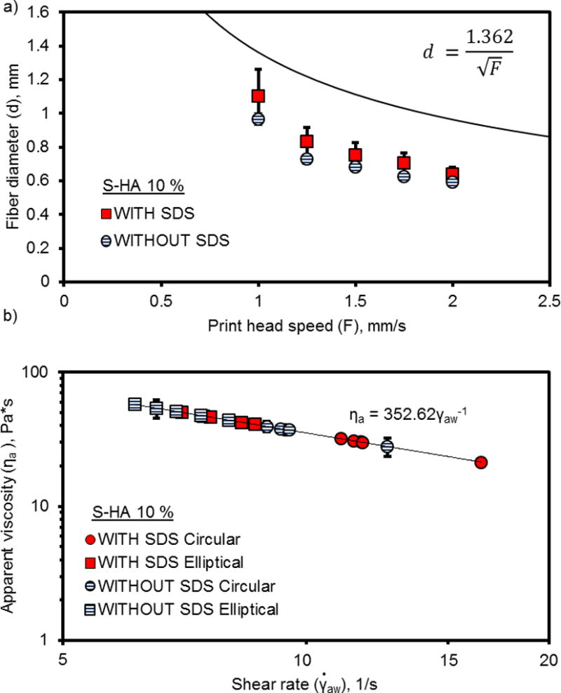
Fiber diameter measurements (a) and apparent viscosity (b) of PPF-HA (10 wt%) solutions with or without surfactant (SDS) printed at constant pressure, constant temperature, and varied speed. Printing solutions extruded with a 0.840 mm (inner diameter) syringe tip. Measurements reported as mean ± standard deviation (n = 3).
Representative images of S-HA 10 % scaffolds with or without SDS
During scaffold printing, the printer took sequential images of each layer. The representative images in Figure S1 demonstrate that both printing solutions with and without SDS produced scaffolds with continuous fibers, uniform layers, and fully interconnected pores. The uniformity of fibers diminished in higher layers. Although the layer-by-layer images in Figure S1 only represent S-HA 10 % scaffolds with SDS, comparative images of scaffolds without SDS had almost identical fiber morphology, connectivity, and uniformity in each layer. From the cross-sectional image in Figure S1d, the fibers appeared relatively spherical in shape. Similar results were observed for scaffolds without SDS.
Scaffold architecture, porosity, and compressive mechanical properties
After printing multi-layer scaffolds, we were interested in understanding the effect of surfactant on scaffold architecture, including fiber diameter, pore size, and the spacing between neighboring fibers within each layer. Figure 3 confirmed results from imaging, demonstrating a better uniformity of fibers and pores in initial layers (Layers 1–3) than in higher layers (indicated by smaller standard deviations). Additionally, the incorporation of surfactant did not appear to affect layer uniformity (indicated by comparable standard deviations in each layer), which also confirms results from the images. The Supplemental Information for this work includes all of the statistical analysis for Figure 3, which compares each layer by ANOVA.
Figure 3.
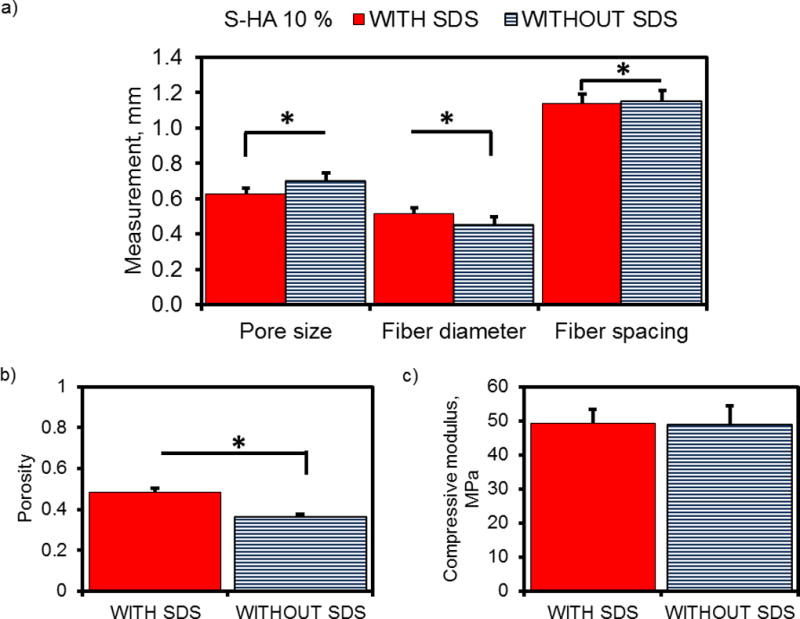
Layer-by-layer analysis of 3D printed PPF-HA (10 wt%) scaffolds with or without surfactant (SDS). (a) Pore size, (b) fiber diameter, and (c) fiber spacing measurements are reported as mean + standard deviation. Each datum represents 8 scaffolds with 5 measurements per layer (n = 40 measurements per datum).
However, when we compare scaffold architecture as a whole (Figure 4a), the incorporation of SDS significantly decreased fiber diameter (SDS = 0.63 ± 0.14 mm and without SDS = 0.70 ± 0.13 mm, p < 0.0001) and increased pore size (SDS = 0.52 ± 0.13 mm and without SDS = 0.45 ± 0.12 mm, p < 0.0001). The center-to-center spacing between neighboring fibers (which was set by the printing software to be 1.2mm), was also greater for scaffolds without SDS (SDS = 1.14 ± 0.19 mm and without SDS = 1.15 ± 0.19 mm, p = 0.0122). Additionally, the porosity of scaffolds containing SDS was significantly higher (SDS = 0.49 ± 0.02 and without SDS = 0.36 ± 0.01, p < 0.0001) (Figure 4b). Upon comparison of compressive mechanical properties, both formulations exhibited similar compressive moduli (SDS = 49.2 ± 4.2 MPa and without SDS = 48.9 ± 5.6 MPa, p = 0.9408) (Figure 4c).
Figure 4.
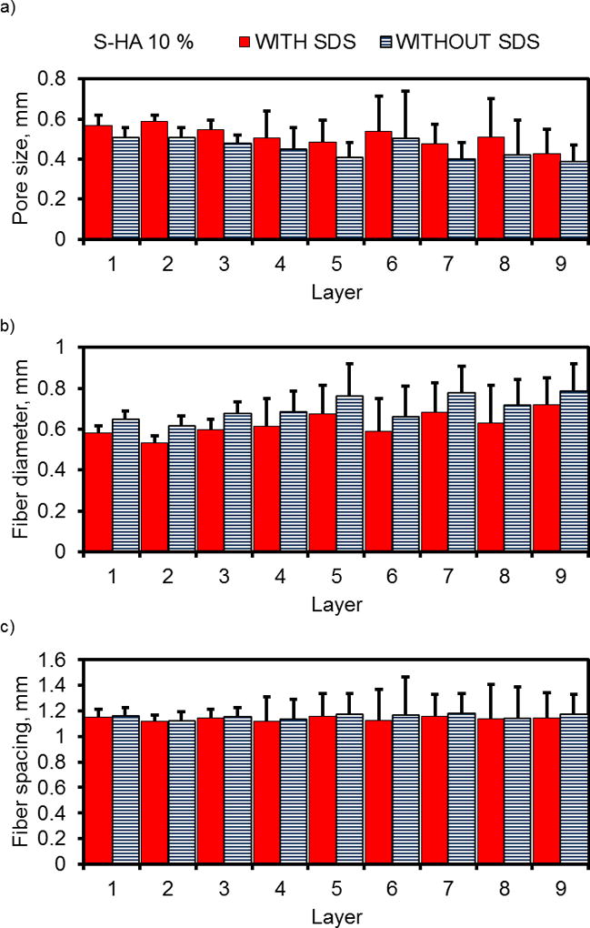
Summary of mean pore and fiber measurements, porosity, and compressive mechanical properties of PPF-HA (10 wt%) scaffolds with and without surfactant (SDS). (a) Pore size, fiber diameter, and fiber spacing of scaffolds. Each datum represents the mean of layer-by-layer data points from Figure 3. (b) Porosity determined via gravimetric analysis and (c) compressive modulus. Data reported as mean + standard deviation (n = 4). *Asterisk indicates statistical significance between groups with SDS and without SDS, p < 0.05.
Fabrication of 3D printed bilayer and gradient scaffolds containing PPF and HA
Fiber diameter of single strands and viscosity of printing solutions
From these results, we have demonstrated the ability to print S-HA 10 % scaffolds with fully interconnected pores and found that the incorporation of SDS did not improve overall HA dispersion, layer uniformity, or compressive mechanical properties. Thus, we continued fabrication of bilayer and gradient scaffolds without the use of surfactant for the remaining studies in this work.
Upon moving forward with the fabrication of scaffolds with complex compositions, however, we observed complications when combining printing solutions with varying HA concentrations. Specifically, HA concentration drastically affected printing solution viscosity and subsequent scaffold properties. At identical printing settings (temperature, pressure, and printing speed), the B-HA 0 % printing solution had a much lower viscosity than the B-HA 10 % solution, which caused B-HA 0 % fibers to spread more during printing (Figure 5a). Consequently, the printing settings had to be changed in order to increase the B-HA 0 % apparent viscosity and extrude fibers with similar diameters since the syringe tip diameter remained constant. This was also true for printing solutions with four different concentrations of HA. More fiber spreading was observed for solutions containing smaller quantities of HA (1.25 and 2.5 wt%), while the most concentrated solutions (5 and 10 wt%) exhibited the least spreading (Figure 6a). All solutions exhibited shear-thinning behavior (Figure 5b and Figure 6b). After adjusting printing settings to accommodate varying HA concentrations (Table 3), the groupings of printing solutions with statistically equivalent apparent viscosities are ranked from high to low as follows: 1) B-HA 0 %, G-HA 5 %, and G-HA 10 %; 2) B-HA 0 %, G-HA 1.25 %, and G-HA 2.5 %; and 3) G-HA 1.25 %, G-HA 2.5 %, and B-HA 10 %.
Figure 5.
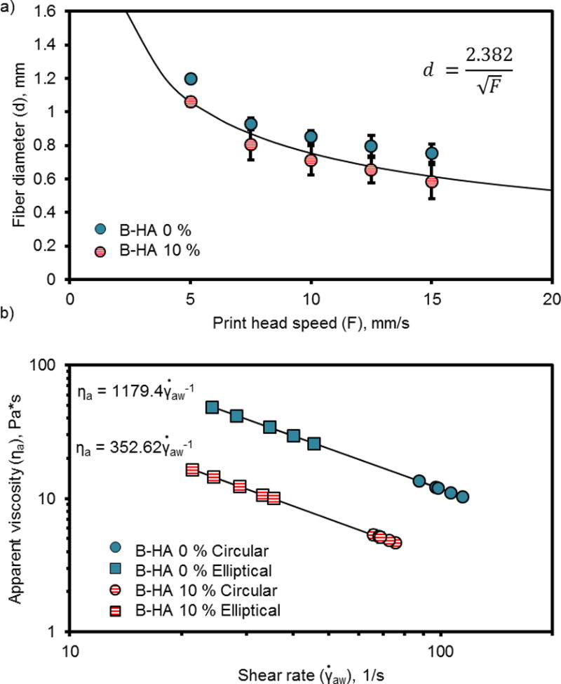
Fiber diameter measurements (a) and apparent viscosity (b) of PPF and PPF-HA (10 wt%) solutions printed at varied temperature, pressure, and speed to print fibers with similar diameters. Printing solutions extruded with a 0.840 mm (inner diameter) syringe tip. Measurements reported as mean ± standard deviation (n = 3).
Figure 6.
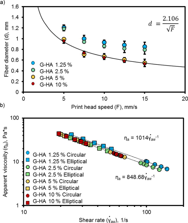
Fiber diameter measurements (a) and apparent viscosity (b) of PPF-HA solutions (containing 1.25, 2.5, 5 and 10 wt% HA) printed at varied temperature, pressure (0.4 bar for 1.25 wt%, 0.5 bar for 2.5, 5, and 10 wt%), and speed to print fibers with similar diameters. Printing solutions extruded with a 0.840 mm (inner diameter) syringe tip. Measurements reported as mean ± standard deviation (n = 3).
Representative images of bilayer and gradient scaffolds
From the representative images in Figure S2–S3, fiber fusion and sagging were observed to the point that pores were no longer interconnected as compared to the S-HA 10 % scaffolds (with or without SDS). We observed that bilayer scaffolds had more continuous fibers in each layer (Figure S2) than gradient scaffolds (Figure S3), which is evident in the layer-by-layer images.
Scaffold architecture and porosity of bilayer and gradient scaffolds
Compared to S-HA 10 % scaffolds with or without SDS, the bilayer scaffolds had a significantly lower porosity (0.23 ± 0.05 for bilayer, 0.49 ± 0.02 for S-HA 10 % with SDS, 0.36 ± 0.01 for S-HA 10 % without SDS, p < 0.05) (Figure 7). Gradient scaffolds had a comparable porosity to S-HA 10 % scaffolds without SDS, regardless of whether they were printed in descending concentration (0.33 ± 0.11) or ascending concentration (0.33 ± 0.02). We also measured the pore size, fiber diameter, and fiber spacing for bilayer and descending gradient scaffolds (Figure 8). The mean scaffold fiber diameter was significantly smaller for G-HA 10 % and G-HA 5 % layers in gradient scaffolds (statistical analysis in Supplemental Information). On the other hand, the largest pore sizes were found in layers containing G-HA 5 %, G-HA 10 %, B-HA 0 %, or B-HA 10 %. The fiber diameter stayed constant regardless of layer or HA concentration (statistical analysis in Supplemental Information). As before with the S-HA 10 % scaffolds with or without SDS, the layer uniformity declined within higher layers. It should be noted that the standard deviations for the bilayer and gradient scaffolds increased when compared with the S-HA 10 % scaffolds (with and without SDS), which indicated a diminished uniformity for these scaffolds.
Figure 7.
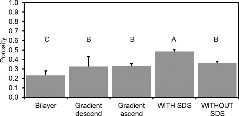
Porosity of bilayer and gradient scaffolds compared to uniform PPF-HA scaffolds. Porosity data for PPF-HA scaffolds (with SDS, without SDS) taken from b. Data reported as mean + standard deviation (n = 4). Gradient descend scaffolds were printed with 10 wt% HA solution on bottom (descending order). Gradient ascend scaffolds were printed with 1.25 wt% HA solution on bottom (ascending order). Values with the same letter (A–C) are not statistically different (p ≥ 0.05).
Figure 8.
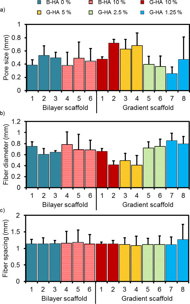
(a) Pore size, (b) fiber diameter, and (c) fiber spacing measurements organized by scaffold type (bilayer or gradient descending), layer number (1–6 or 1–8), and HA concentration (0–10 wt%). (n = 4 scaffolds per group, 5 measurements per layer for a total of 20 measurements per datum). Data reported as mean + standard deviation (n = 4).
µCT analysis of HA aggregates and distribution within PPF-HA composite scaffolds
Previous work demonstrated the ability to evaluate HA distribution within a polymer composite scaffold via µCT [40]. We were interested in qualitatively investigating the distribution of HA nanoparticles within the PPF matrix and compared S-HA 10 % scaffolds with and without SDS. At this resolution (~10 µm), it was difficult to identify the dispersion of HA nanoparticles within the polymer, but it was possible to visualize large aggregates (Figure 9). Similar aggregates were apparent regardless of the presence of SDS, meaning that the surfactant did not effectively facilitate uniform dispersion of the particles within the scaffold. Additionally, we used µCT to visually represent the HA distribution in gradient scaffolds. We observed similar HA aggregates within the gradient scaffolds but had difficulties distinguishing a gradient of nanoparticles due to the scanning resolution (Figure 9b).
Figure 9.
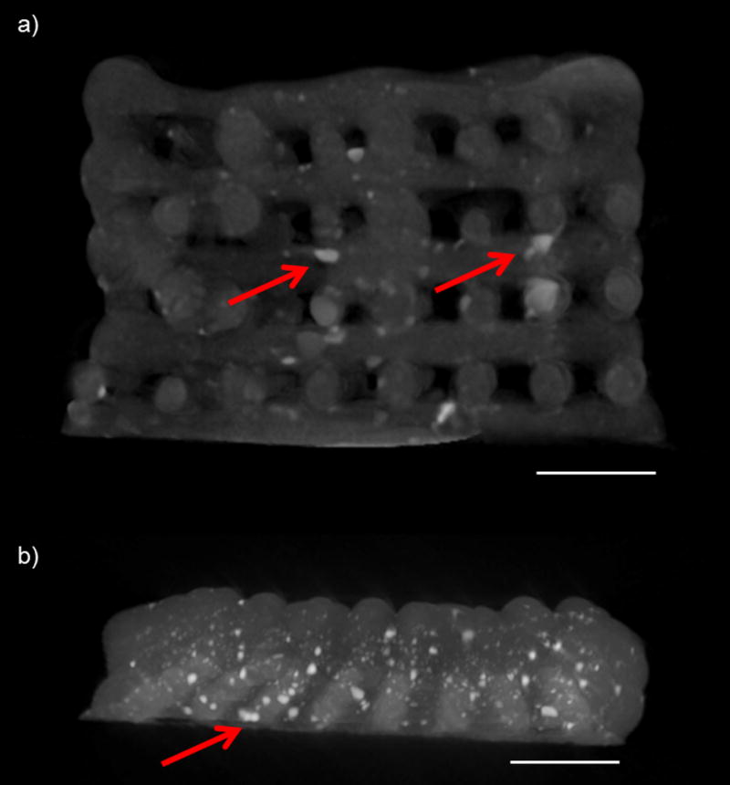
Cross-sectional images of (a) a PPF-HA scaffold without SDS (containing a uniform concentration of HA) and (b) a PPF-HA gradient scaffold. Images generated from a 3D reconstruction via µCT. Scale bars in both images = 2 mm. Arrows point to noticeable aggregates of HA, which are apparent as white, opaque clusters within dark gray PPF matrix.
Thermogravimetric analysis (TGA) to confirm HA gradient
Thermal analysis enabled confirmation of an HA gradient within 3D printed layers (Figure 10a). In general, it was possible to distinguish the following distinct concentrations: PPF only (−0.02 ± 0.42); PPF-HA 1.25 wt% (3.90 ± 0.54) or 2.5 wt% (4.48 ± 0.27); PPF-HA 5 wt% (7.47 ± 0.64); and PPF-HA 10 wt% (12.22 ± 0.02). Quantitative measurements were more accurate for formulations with greater HA concentration (Figure 10b). It should be noted that there was an uncharacteristic behavior between 400–500 °C. We analyzed PPF and PPF-HA (10 wt%) up to 700 °C under oxygen and nitrogen atmospheres and plotted their profiles (temperature vs. time and weight % vs. time in Figure S1). Between 400–500 °C, we recognized a sharp peak – related to mass loss of PPF – under an oxygen atmosphere that was absent under the nitrogen atmosphere (Figure S4). This behavior was observed for both for both PPF and PPF-HA (Figure S4a and b).
Figure 10.
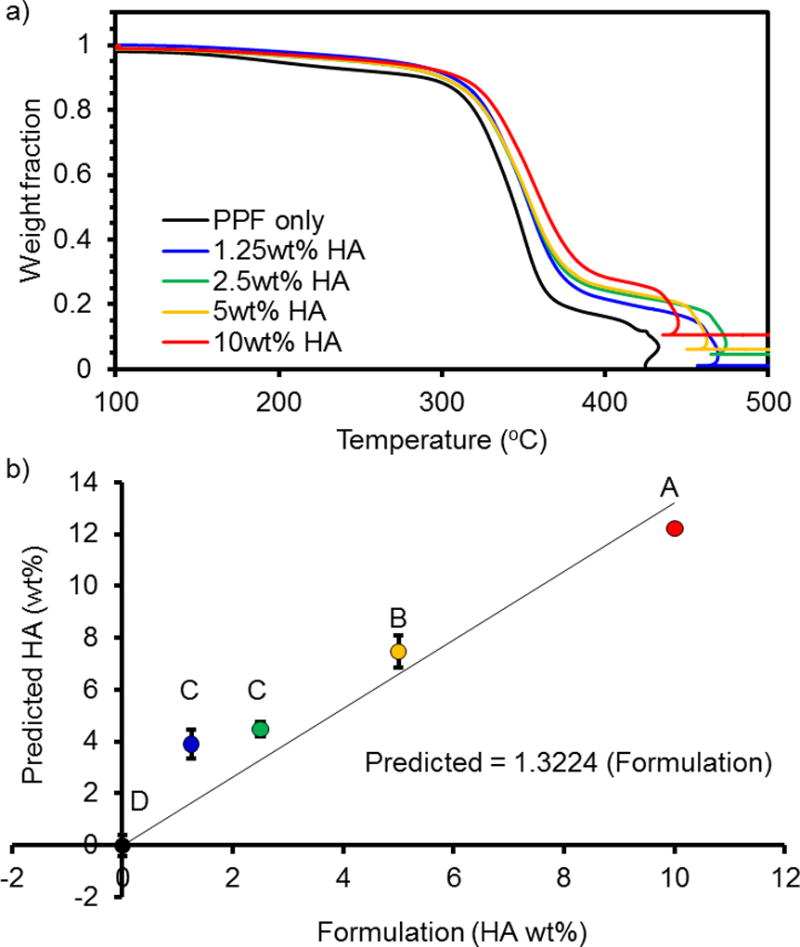
Thermogravimetric analysis (TGA) of HA gradient in PPF-HA composites for 0, 1.25, 2.5, 5, and 10 wt% HA. (a) Data are normalized to the initial weight after the evaporation of water at 100 °C. Peak at ~450 °C for all samples indicates a combustion peak for PPF, a drastic change that causes a sudden decrease and subsequent increase in temperature within the TGA furnace. See Figure S4 for TGA profile of PPF and PPF-HA as a function of time. (b) Data plotted as predicted value (wt% HA) vs formulation. *Formulations marked with the same letter (A–D) are not statistically different (p ≥ 0.05).
Discussion
For S-HA 10 % scaffolds, the fiber diameter was not affected by the presence of SDS. However, SDS lowered apparent viscosity for both circular and elliptical cross-section models. When the fibers were modeled with elliptical cross-sections, apparent viscosity increased for both groups, which is understandable because the estimated flow rate of material decreases with an elliptical cross-sectional area. In both scaffolds with and without SDS, we found that each layer contained continuous fibers and fully interconnected pores. Pore sizes were between 0.600–0.800 mm, which is a relevant range for bone tissue engineering [5, 18, 41–44]. We also observed a decline in uniformity with higher layers, which is common for 3D printed scaffolds. If the z height (layer thickness) is too high or too low, layer detachment or fusion, respectively, is propagated in an additive manner. Interestingly, we found that SDS did not affect the fiber morphology or the uniformity within layers. However, SDS did affect fiber diameter, pore size, and porosity, which is likely due its role in decreasing surface tension [45].
Due to the difference in porosity, we expected a difference in compressive mechanical properties based on reported work [34, 46]. Contrary to these reports, however, it appears that the differences in pore size and fiber diameter also affected the mechanical properties. The compressive modulus for both S-HA 10 % scaffolds with and without SDS was about 50 MPa, which is greater than or comparable to previous reports with 3D printed polymers (20–90 MPa) [34], 3D printed composites (30–100 MPa) [40], and non-porous PPF-HA composites (20–60 MPa [27] and 135–150 MPa [28]). Our S-HA 10 % scaffolds also showed similar porosity and scaffold architecture to PPF-HA composites prepared via STL [47]; however, our results showed an improvement in compressive modulus with extrusion-based printing techniques. After comparing our results to other literature, it is notable that the incorporation of fully interconnected pores does not dramatically compromise mechanical properties, and the scaffolds fabricated in this work would facilitate waste and nutrient transport much more effectively in vitro and in vivo than non-porous composites. In the event that the bilayer and gradient scaffolds had interconnected pores, allowing us to accurately perform compressive testing, it would be important to evaluate the effect of varying photoinitiator concentration on mechanical properties, which would likely contribute in addition to the HA concentration.
Based on guidelines from previous work, the S-HA 10 % scaffolds would constitute successful prints [15]. However, the bilayer and gradient scaffolds exhibited higher variability in the layer-by-layer analysis and did not have interconnected pores, which would limit their effectiveness for mass transport in vivo. The importance of molecular weight should also be mentioned, since the molecular weight used for S-HA 10 % scaffolds was higher than for the bilayer and gradient scaffolds. Although mechanical properties were not evaluated for bilayer and gradient scaffolds, scaffolds prepared with a lower molecular weight would likely have lower compressive moduli [35]. The higher molecular weight PPF would have also increased the viscosity of the printing solutions [15, 35], which would consequently have an impact on scaffold architecture.
Non-destructive analysis methods were also used to evaluate the scaffold architecture and distribution of composite phases. Large aggregates of HA were observed throughout the PPF matrix via µCT. Although µCT gives qualitative information about HA particle distribution, the resolution of most instruments is not precise enough (~10 µm) to identify individual nanoparticles in 3D reconstructions. Therefore, scaffolds with gradient HA content could not be distinguished from scaffolds with uniform HA content. Other reported strategies to characterize dispersion include Raman spectroscopy [9] and FT-IR [28], which are also relevant for quantitatively analyzing nanoparticle distribution. It is likely, however, that the 3D printed scaffold geometry would complicate analysis using these techniques, which are primarily performed on non-porous films. It is notable that HA aggregation and nanoparticle concentration not only affected the rheological behavior of printing solutions, but aggregation also physically occluded small orifices, limiting the syringe diameters that could be used for extrusion. The ability to extrude fibers smaller than 0.500 mm is limited with this preparation. Some reports have offered alternatives to improve dispersion, including modifying the PPF chemistry with carboxy- termination to facilitate surface attachment of the HA to the polymer chains [9]. Conductive coatings have also been used to modify the PPF surface [48]. Other authors prepared a colloidal dispersion of HA in PPF for STL by first dispersing nanoparticles in ethanol, mixing with DEF, and then mixing with PPF and evaporating the ethanol [31]. However, particle settling and spatial dispersion of the particles was not evaluated, and these are important considerations for successfully printing monodisperse scaffolds with STL and extrusion-based 3D printing.
Although µCT analysis primarily served as a qualitative measure of particle aggregation, TGA can quantify the amount of HA in gradient layers if they are separated. The machine sensitivity was not able to detect the differences between 1.25 wt% and 2.5 wt% HA. However, we have performed TGA on scaffolds containing a greater difference in concentration (10 wt% increments) that provide distinctions with much greater accuracy (data not shown). Our initial degradation profiles were similar to those reported in previous reports [27, 31, 48]. In this study, we chose to use oxygen gas instead of nitrogen in order to burn off the excess PPF residue remaining in the sample pan, leaving only the ceramic phase at the end of the sample run. Since nitrogen gas is inert, the combustion of polymer is prevented during the ramping to high temperature, as indicated by the drastic mass loss at around 40 min for the oxygen environment and the lack of mass loss for the nitrogen environment (Figure S4). Because of this behavior, the use of oxygen gas allowed us to more accurately quantify the HA within each layer. Other work performed with nitrogen gas reported a thermal degradation temperature of 400 °C for PPF-co-poly(ε-caprolactone) (PCL), which is consistent with our results [28].
For future in vitro applications, we would anticipate that the incorporation of HA would improve cell attachment and proliferation based on previous reports [27, 28]. The exposure of HA to the surface plays an important role in promoting cell adhesion and can be difficult to achieve in scaffolds with micro- and macro-scale fibers. However, previous work demonstrated enhanced exposure of HA to the surface of PPF-co-PCL films with increased HA concentration (up to 30 wt%) via SEM and FT-IR [28]. HA exposure depends both on the method of scaffold fabrication and the efforts made to disperse the nanoparticles. Another report used flow perfusion and surface coating of PPF with HA to improve cell attachment on scaffolds fabricated via STL [48].
For future in vivo implantation, 3D printed PPF-HA scaffolds can provide improved mechanical support for load-bearing implants as compared to PPF-HA scaffolds fabricated via indirect casting [49], molds [27], or STL [44, 50]. Furthermore, the osteoconductive properties of HA would allow bone to form within the scaffold’s pores and integrate with the surface. The molecular weight used for this study would mechanically support tissue infiltration during scaffold degradation based on reports from other work [35, 51, 52].
Conclusions
In this work, we have provided a systematic characterization of composite polymer/ceramic scaffolds with HA gradients. We have quantitatively evaluated the HA content in each layer using thermal analysis and qualitatively assessed the particle aggregation within the polymer matrix using µCT. Additionally, we have characterized the effects of adding a surfactant, SDS, to improve the dispersion of HA nanoparticles. We observed that SDS affected scaffold architecture and porosity. However, architecture and porosity balanced each other in a way that SDS did not impact compressive mechanical properties, and we were able to print scaffolds that would serve as mechanically robust implants. Upon printing complex scaffolds with multiple printing solutions, it is notable that solution viscosity determines scaffold architecture within each layer and drastically affects scaffold uniformity. This is a crucial consideration for printing slurries of a variety of components, including polymer/ceramic solutions, metal slurries, and hydrogel/cell solutions, among others. This work provides insight for proper fabrication and characterization of composite scaffolds containing nanoparticle gradients and is important for future efforts in fabricating complex scaffolds for tissue engineering applications.
Supplementary Material
Table S1. 3D printing parameters for PPF and PPF-HA printing solutions
Figure S1. Representative images of PPF-HA (10 wt%) scaffolds with or without surfactant (SDS). PPF-HA scaffolds comprise 9 layers (a) with fully interconnected pores (b), observed via optical microscopy. Representative (c) top and (d) cross-section (rotated view in Figure 1d) views obtained via SEM. (a)(b)(d) with SDS, (c) without SDS. Scale bars in (a, Layers 1–9) represent 1 mm and in (b) represent 2 mm. Pore size and fiber diameter measured in each layer of the scaffold (a).
Figure S2. Representative images of PPF/PPF-HA (10 wt%) bilayer scaffolds. (a) PPF/PPF-HA bilayer scaffold comprises 6 layers, obtained via optical microscopy. Representative (b) top and (c) cross-section views (rotated view in Figure 1e) obtained via SEM. Scale bars in (a, Layers 1–6) represent 1 mm. Pore size and fiber diameter measured in each layer of the scaffold (a).
Figure S3. Representative images of PPF-HA gradient scaffolds. (a) PPF-HA gradient scaffold comprises 8 layers, with 10 wt% HA printed within the bottom layer (descending order), obtained via optical microscopy. Representative (b) top and (c) cross-section (rotated view in Figure 1f) views obtained via SEM. Scale bars in (a, Layers 1–8) represent 1 mm. Pore size and fiber diameter measured in each layer of the scaffold (a).
Figure S4. Representative TGA profiles of (a) PPF and (b) PPF-HA (10 wt%) under oxygen (O2) and nitrogen (N2) atmospheres (up to 700 °C). Small inflection at ~40 min (under O2 atmosphere between 400 and 500 °C) indicates a large mass loss of the PPF polymer due to combustion of the remaining carbon residue. Weight % data are normalized to the initial weight after the evaporation of water at 100 °C. Similar behavior was observed for both (a) PPF and (b) PPF-HA.
Acknowledgments
We acknowledge Dr. Matteo Pasquali for his assistance with the viscosity analysis and Dr. Marco Santoro for his feedback on the manuscript. We also would like to thank Dr. Daniel Puperi for his assistance in developing custom Python code for the compressive mechanical analysis.
Funding
This work was supported by the National Institutes of Health [R01 CA180279, R01 AR068073, and R01 AR061460 (Bioplotter printing system)], the National Science Foundation [Graduate Research Fellowship], and the Howard Hughes Medical Institute [Graduate Fellowship].
Glossary
Abbreviations
- AFM
Atomic force microscopy
- ANOVA
Analysis of variance
- BAPO
Phenylbis(2,4,6-trimethylbenzoyl)-phosphine oxide
- DEF
Diethyl fumarate
- DMSO
Dimethyl sulfoxide
- ECM
Extracellular matrix
- FT-IR
Fourier transform-infrared spectroscopy
- HA
Hydroxyapatite
- HSD
(Tukey’s) Honestly Significant Difference test
- PDI
Polydispersity index
- PPF
Poly(propylene fumarate)
- PPF-co-PCL
Poly(propylene fumarate)-co-poly(ε-caprolactone)
- SDS
Sodium dodecyl sulfate
- SEM
Scanning electron microscopy
- STL
Stereolithography
- TGA
Thermogravimetric analysis
- µCT
Micro-computed tomography
Symbols
- γ̇aw
Wall shear rate
- τw
Wall shear stress
- ΔP
Pressure drop
- d
Fiber diameter
- ds
Syringe diameter
- F
Printing speed
- L
Scaffold length
- Ls
Syringe length
- Mn
Number average molecular weight
- mscaffold
Scaffold mass
- P
Pressure
- Papp
Applied pressure
- Patm
Atmospheric pressure
- Q
Flow rate
- H
Scaffold thickness
- T
Temperature
- W
Scaffold width
- z
Layer thickness
- ρmaterial
Material density
- ρscaffold
Scaffold density
Footnotes
Disclosure statement
No potential conflict of interest is reported by JET, BTS, and AGM. JKP and JPF are founders of the company 3DBioworks.
References
- 1.Castro NJ, Hacking SA, Zhang LG. Recent progress in interfacial tissue engineering approaches for osteochondral defects. Ann Biomed Eng. 2012;40:1628–40. doi: 10.1007/s10439-012-0605-5. [DOI] [PubMed] [Google Scholar]
- 2.Bhattacharjee M, Chameettachal S, Pahwa S, et al. Strategies for replicating anatomical cartilaginous tissue gradient in engineered intervertebral disc. ACS Appl Mater Interfaces. 2014;6:183–93. doi: 10.1021/am403835t. [DOI] [PubMed] [Google Scholar]
- 3.Castro NJ, O'Brien J, Zhang LG. Integrating biologically inspired nanomaterials and table-top stereolithography for 3D printed biomimetic osteochondral scaffolds. Nanoscale. 2015;7:14010–22. doi: 10.1039/c5nr03425f. [DOI] [PMC free article] [PubMed] [Google Scholar]
- 4.Nie T, Xue L, Ge M, et al. Fabrication of poly(L-lactic acid) tissue engineering scaffolds with precisely controlled gradient structure. Mater Lett. 2016;176:25–8. [Google Scholar]
- 5.Sobral JM, Caridade SG, Sousa RA, et al. Three-dimensional plotted scaffolds with controlled pore size gradients: Effect of scaffold geometry on mechanical performance and cell seeding efficiency. Acta Biomater. 2011;7:1009–18. doi: 10.1016/j.actbio.2010.11.003. [DOI] [PubMed] [Google Scholar]
- 6.Hao J, Yuan M, Deng X. Biodegradable and biocompatible nanocomposites of poly(ε-caprolactone) with hydroxyapatite nanocrystals: Thermal and mechanical properties. J Appl Polym Sci. 2002;86:676–83. [Google Scholar]
- 7.Pezzatini S, Solito R, Morbidelli L, et al. The effect of hydroxyapatite nanocrystals on microvascular endothelial cell viability and functions. J Biomed Mater Res A. 2006;76:656–63. doi: 10.1002/jbm.a.30524. [DOI] [PubMed] [Google Scholar]
- 8.Zakaria SM, Sharif Zein SH, Othman MR, et al. Hydroxyapatite nanoparticles: electrospinning and calcination of hydroxyapatite/polyvinyl butyral nanofibers and growth kinetics. J Biomed Mater Res A. 2013;101:1977–85. doi: 10.1002/jbm.a.34506. [DOI] [PubMed] [Google Scholar]
- 9.Victor SP, Muthu J. Bioactive, mechanically favorable, and biodegradable copolymer nanocomposites for orthopedic applications. Mater Sci Eng C Mater Biol Appl. 2014;39:150–60. doi: 10.1016/j.msec.2014.02.031. [DOI] [PubMed] [Google Scholar]
- 10.Yang Y, Liang X, Chen W, et al. Quantification and promotion of interfacial interactions between carbon nanotubes and polymer derived ceramics. Carbon. 2015;95:964–71. [Google Scholar]
- 11.Sousa RA, Reis RL, Cunha AM, et al. Structure development and interfacial interactions in high-density polyethylene/hydroxyapatite (HDPE/HA) composites molded with preferred orientation. J Appl Polym Sci. 2002;86:2873–86. [Google Scholar]
- 12.Kokkinis D, Schaffner M, Studart AR. Multimaterial magnetically assisted 3D printing of composite materials. Nat Commun. 2015;6 doi: 10.1038/ncomms9643. [DOI] [PMC free article] [PubMed] [Google Scholar]
- 13.Fisher JP, Vehof JW, Dean D, et al. Soft and hard tissue response to photocrosslinked poly(propylene fumarate) scaffolds in a rabbit model. J Biomed Mater Res. 2002;59:547–56. doi: 10.1002/jbm.1268. [DOI] [PubMed] [Google Scholar]
- 14.Vehof JW, Fisher JP, Dean D, et al. Bone formation in transforming growth factor beta-1-coated porous poly(propylene fumarate) scaffolds. J Biomed Mater Res. 2002;60:241–51. doi: 10.1002/jbm.10073. [DOI] [PubMed] [Google Scholar]
- 15.Trachtenberg JE, Placone JK, Smith BT, et al. Extrusion-Based 3D Printing of Poly(propylene fumarate) in a Full-Factorial Design. ACS Biomaterials Science & Engineering. 2016;2:1771–80. doi: 10.1021/acsbiomaterials.6b00026. [DOI] [PubMed] [Google Scholar]
- 16.Kim K, Dean D, Lu A, et al. Early osteogenic signal expression of rat bone marrow stromal cells is influenced by both hydroxyapatite nanoparticle content and initial cell seeding density in biodegradable nanocomposite scaffolds. Acta Biomater. 2011;7:1249–64. doi: 10.1016/j.actbio.2010.11.007. [DOI] [PMC free article] [PubMed] [Google Scholar]
- 17.Kim K, Dean D, Wallace J, et al. The influence of stereolithographic scaffold architecture and composition on osteogenic signal expression with rat bone marrow stromal cells. Biomaterials. 2011;32:3750–63. doi: 10.1016/j.biomaterials.2011.01.016. [DOI] [PMC free article] [PubMed] [Google Scholar]
- 18.Karageorgiou V, Kaplan D. Porosity of 3D biomaterial scaffolds and osteogenesis. Biomaterials. 2005;26:5474–91. doi: 10.1016/j.biomaterials.2005.02.002. [DOI] [PubMed] [Google Scholar]
- 19.Relvas C, Ramos A, Completo A, et al. A systematic approach for an accuracy level using rapid prototyping technologies. Proc Inst Mech Eng Pt B: J Eng Manuf. 2012;226:2023–34. [Google Scholar]
- 20.Hardin JO, Ober TJ, Valentine AD, et al. Microfluidic Printheads for Multimaterial 3D Printing of Viscoelastic Inks. Adv Mater. 2015;27:3279–84. doi: 10.1002/adma.201500222. [DOI] [PubMed] [Google Scholar]
- 21.Kolesky DB, Truby RL, Gladman AS, et al. 3D bioprinting of vascularized, heterogeneous cell-laden tissue constructs. Adv Mater. 2014;26:3124–30. doi: 10.1002/adma.201305506. [DOI] [PubMed] [Google Scholar]
- 22.Rutz AL, Hyland KE, Jakus AE, et al. A multimaterial bioink method for 3D printing tunable, cell-compatible hydrogels. Adv Mater. 2015;27:1607–14. doi: 10.1002/adma.201405076. [DOI] [PMC free article] [PubMed] [Google Scholar]
- 23.Hinton TJ, Jallerat Q, Palchesko RN, et al. Three-dimensional printing of complex biological structures by freeform reversible embedding of suspended hydrogels. Sci Adv. 2015;1:e1500758. doi: 10.1126/sciadv.1500758. [DOI] [PMC free article] [PubMed] [Google Scholar]
- 24.Jakus AE, Shah RN. Multi- and mixed 3D-printing of graphene-hydroxyapatite hybrid materials for complex tissue engineering. J Biomed Mater Res A. 2016 doi: 10.1002/jbm.a.35684. [DOI] [PubMed] [Google Scholar]
- 25.Trachtenberg JE, Vo TN, Mikos AG. Pre-clinical characterization of tissue engineering constructs for bone and cartilage regeneration. Ann Biomed Eng. 2015;43:681–96. doi: 10.1007/s10439-014-1151-0. [DOI] [PMC free article] [PubMed] [Google Scholar]
- 26.Vo TN, Trachtenberg JE, Mikos AG. In vitro techniques for biomaterial evaluation in bone and cartilage tissue engineering. J Japanese Soc Regen Med. 2014;13:125–49. [Google Scholar]
- 27.Lee KW, Wang S, Yaszemski MJ, et al. Physical properties and cellular responses to crosslinkable poly(propylene fumarate)/hydroxyapatite nanocomposites. Biomaterials. 2008;29:2839–48. doi: 10.1016/j.biomaterials.2008.03.030. [DOI] [PMC free article] [PubMed] [Google Scholar]
- 28.Becker J, Lu L, Runge MB, et al. Nanocomposite bone scaffolds based on biodegradable polymers and hydroxyapatite. J Biomed Mater Res A. 2015;103:2549–57. doi: 10.1002/jbm.a.35391. [DOI] [PubMed] [Google Scholar]
- 29.Kasper FK, Tanahashi K, Fisher JP, et al. Synthesis of poly(propylene fumarate) Nat Protoc. 2009;4:518–25. doi: 10.1038/nprot.2009.24. [DOI] [PMC free article] [PubMed] [Google Scholar]
- 30.Dean D, Jonathan W, Siblani A, et al. Continuous Digital Light Processing (cDLP): Highly Accurate Additive Manufacturing of Tissue Engineered Bone Scaffolds. Virtual Phys Prototyp. 2012;7:13–24. doi: 10.1080/17452759.2012.673152. [DOI] [PMC free article] [PubMed] [Google Scholar]
- 31.Farkas B, Rodio M, Romano I, et al. Fabrication of hybrid nanocomposite scaffolds by incorporating ligand-free hydroxyapatite nanoparticles into biodegradable polymer scaffolds and release studies. Beilstein J Nanotechnol. 2015;6:2217–23. doi: 10.3762/bjnano.6.227. [DOI] [PMC free article] [PubMed] [Google Scholar]
- 32.Macosko CW. Rheology: Principles, Measurements, and Applications. 1. Poughkeepsie, NY: Wiley-VCH; 1994. Shear rheometry: Pressure-driven flows; p. 242. [Google Scholar]
- 33.Miller JS, Stevens KR, Yang MT, et al. Rapid casting of patterned vascular networks for perfusable engineered three-dimensional tissues. Nat Mater. 2012;11:768–74. doi: 10.1038/nmat3357. [DOI] [PMC free article] [PubMed] [Google Scholar]
- 34.Trachtenberg JE, Mountziaris PM, Miller JS, et al. Open-source three-dimensional printing of biodegradable polymer scaffolds for tissue engineering. J Biomed Mater Res A. 2014;102:4326–35. doi: 10.1002/jbm.a.35108. [DOI] [PMC free article] [PubMed] [Google Scholar]
- 35.Wang S, Lu L, Yaszemski MJ. Bone-Tissue-Engineering Material Poly(propylene fumarate): Correlation between Molecular Weight, Chain Dimensions, and Physical Properties. Biomacromolecules. 2006;7:1976–82. doi: 10.1021/bm060096a. [DOI] [PMC free article] [PubMed] [Google Scholar]
- 36.Tseng H, Puperi DS, Kim EJ, et al. Anisotropic poly(ethylene glycol)/polycaprolactone hydrogel-fiber composites for heart valve tissue engineering. Tissue Eng Part A. 2014;20:2634–45. doi: 10.1089/ten.tea.2013.0397. [DOI] [PMC free article] [PubMed] [Google Scholar]
- 37.Zhang X, Xu B, Puperi DS, et al. Integrating valve-inspired design features into poly(ethylene glycol) hydrogel scaffolds for heart valve tissue engineering. Acta Biomater. 2015;14:11–21. doi: 10.1016/j.actbio.2014.11.042. [DOI] [PMC free article] [PubMed] [Google Scholar]
- 38.Levorson EJ, Santoro M, Kasper FK, et al. Direct and indirect co-culture of chondrocytes and mesenchymal stem cells for the generation of polymer/extracellular matrix hybrid constructs. Acta Biomater. 2014;10:1824–35. doi: 10.1016/j.actbio.2013.12.026. [DOI] [PMC free article] [PubMed] [Google Scholar]
- 39.Mikos AG, Thorsen AJ, Czerwonka LA, et al. Preparation and characterization of poly(l-lactic acid) foams. Polymer. 1994;35:1068–77. [Google Scholar]
- 40.Serra T, Planell JA, Navarro M. High-resolution PLA-based composite scaffolds via 3-D printing technology. Acta Biomater. 2013;9:5521–30. doi: 10.1016/j.actbio.2012.10.041. [DOI] [PubMed] [Google Scholar]
- 41.Solchaga LA, Temenoff JS, Gao J, et al. Repair of osteochondral defects with hyaluronan- and polyester-based scaffolds. Osteoarthritis Cartilage. 2005;13:297–309. doi: 10.1016/j.joca.2004.12.016. [DOI] [PubMed] [Google Scholar]
- 42.Woodfield TB, Van Blitterswijk CA, De Wijn J, et al. Polymer scaffolds fabricated with pore-size gradients as a model for studying the zonal organization within tissue-engineered cartilage constructs. Tissue Eng. 2005;11:1297–311. doi: 10.1089/ten.2005.11.1297. [DOI] [PubMed] [Google Scholar]
- 43.Oh SH, Kim TH, Im GI, et al. Investigation of pore size effect on chondrogenic differentiation of adipose stem cells using a pore size gradient scaffold. Biomacromolecules. 2010;11:1948–55. doi: 10.1021/bm100199m. [DOI] [PubMed] [Google Scholar]
- 44.Lee KW, Wang S, Lu L, et al. Fabrication and characterization of poly(propylene fumarate) scaffolds with controlled pore structures using 3-dimensional printing and injection molding. Tissue Eng. 2006;12:2801–11. doi: 10.1089/ten.2006.12.2801. [DOI] [PubMed] [Google Scholar]
- 45.Neuendorf RE, Saiz E, Tomsia AP, et al. Adhesion between biodegradable polymers and hydroxyapatite: Relevance to synthetic bone-like materials and tissue engineering scaffolds. Acta Biomater. 2008;4:1288–96. doi: 10.1016/j.actbio.2008.04.006. [DOI] [PubMed] [Google Scholar]
- 46.Thomson RC, Yaszemski MJ, Powers JM, et al. Fabrication of biodegradable polymer scaffolds to engineer trabecular bone. J Biomater Sci Polym Ed. 1995;7:23–38. doi: 10.1163/156856295x00805. [DOI] [PubMed] [Google Scholar]
- 47.Lee K-W, Wang S, Dadsetan M, et al. Enhanced Cell Ingrowth and Proliferation through Three-Dimensional Nanocomposite Scaffolds with Controlled Pore Structures. Biomacromolecules. 2010;11:682–9. doi: 10.1021/bm901260y. [DOI] [PMC free article] [PubMed] [Google Scholar]
- 48.Runge MB, Dadsetan M, Baltrusaitis J, et al. Electrically conductive surface modifications of three-dimensional poly(propylene fumarate) scaffolds. J Biol Regul Homeost Agents. 2011;25:S15–S23. [PMC free article] [PubMed] [Google Scholar]
- 49.Alge DL, Bennett J, Treasure T, et al. Poly(propylene fumarate) reinforced dicalcium phosphate dihydrate cement composites for bone tissue engineering. J Biomed Mater Res A. 2012;100:1792–802. doi: 10.1002/jbm.a.34130. [DOI] [PMC free article] [PubMed] [Google Scholar]
- 50.Lee KW, Wang S, Fox BC, et al. Poly(propylene fumarate) bone tissue engineering scaffold fabrication using stereolithography: effects of resin formulations and laser parameters. Biomacromolecules. 2007;8:1077–84. doi: 10.1021/bm060834v. [DOI] [PubMed] [Google Scholar]
- 51.Cai ZY, Yang DA, Zhang N, et al. Poly(propylene fumarate)/(calcium sulphate/beta-tricalcium phosphate) composites: preparation, characterization and in vitro degradation. Acta Biomater. 2009;5:628–35. doi: 10.1016/j.actbio.2008.09.016. [DOI] [PubMed] [Google Scholar]
- 52.Wang MO, Piard CM, Melchiorri A, et al. Evaluating changes in structure and cytotoxicity during in vitro degradation of three-dimensional printed scaffolds. Tissue Eng Part A. 2015;21:1642–53. doi: 10.1089/ten.tea.2014.0495. [DOI] [PMC free article] [PubMed] [Google Scholar]
Associated Data
This section collects any data citations, data availability statements, or supplementary materials included in this article.
Supplementary Materials
Table S1. 3D printing parameters for PPF and PPF-HA printing solutions
Figure S1. Representative images of PPF-HA (10 wt%) scaffolds with or without surfactant (SDS). PPF-HA scaffolds comprise 9 layers (a) with fully interconnected pores (b), observed via optical microscopy. Representative (c) top and (d) cross-section (rotated view in Figure 1d) views obtained via SEM. (a)(b)(d) with SDS, (c) without SDS. Scale bars in (a, Layers 1–9) represent 1 mm and in (b) represent 2 mm. Pore size and fiber diameter measured in each layer of the scaffold (a).
Figure S2. Representative images of PPF/PPF-HA (10 wt%) bilayer scaffolds. (a) PPF/PPF-HA bilayer scaffold comprises 6 layers, obtained via optical microscopy. Representative (b) top and (c) cross-section views (rotated view in Figure 1e) obtained via SEM. Scale bars in (a, Layers 1–6) represent 1 mm. Pore size and fiber diameter measured in each layer of the scaffold (a).
Figure S3. Representative images of PPF-HA gradient scaffolds. (a) PPF-HA gradient scaffold comprises 8 layers, with 10 wt% HA printed within the bottom layer (descending order), obtained via optical microscopy. Representative (b) top and (c) cross-section (rotated view in Figure 1f) views obtained via SEM. Scale bars in (a, Layers 1–8) represent 1 mm. Pore size and fiber diameter measured in each layer of the scaffold (a).
Figure S4. Representative TGA profiles of (a) PPF and (b) PPF-HA (10 wt%) under oxygen (O2) and nitrogen (N2) atmospheres (up to 700 °C). Small inflection at ~40 min (under O2 atmosphere between 400 and 500 °C) indicates a large mass loss of the PPF polymer due to combustion of the remaining carbon residue. Weight % data are normalized to the initial weight after the evaporation of water at 100 °C. Similar behavior was observed for both (a) PPF and (b) PPF-HA.


