Abstract
This paper describes the design and fabrication of a miniature ultrasonic phased array transducer used for intervention guidance. Currently ultrasound probes are often placed at the body surface of the patients, leading to several drawbacks including the limitation of penetration and image quality. In order to improve the reliability of the guiding process, we propose a miniature phased array transducer that can be placed adjacent to the intervention device during the interventional procedure. In this paper, we report the work that has been carried out on the development of this miniature phased array transducer. It comprised 48 elements housed in a 3-mm-diameter needle. A specially designed flexible circuit was used in accommodating the transducer array in the long, thin needle housing. The center frequency and the fractional bandwidth were approximately 20 MHz and 42% respectively, with an average crosstalk lower than −30 dB. The axial and azimuth resolutions were approximately 80 µm and 210 µm respectively. The imaging capability of the transducer was further evaluated by acquiring the B-mode images of a needle in a cow liver. The performance of the proposed phased array transducer demonstrates the feasibility of such an approach for interventional guidance.
Index Terms: miniature transducer, high frequency imaging, ultrasonic transducer array
I. Introduction
Access to diseased tissues is important in clinics for both diagnosis (e.g. biopsy) and therapy delivery (e.g. surgical excision, draining excess fluid). Guiding these procedures has long been one of the major challenges – especially when dealing with internal organs and structures located deep inside the body. The major concern has always been how the device can be tracked safely and accurately. Despite the fact that various techniques have been employed for this purpose, including surface anatomic landmark approach, CT, MRI, etc., each of them has their own limitations.
As its name suggests, anatomic landmark approach relies on locating the target tissue by the relative location between it and some anatomic landmarks, usually at the body surface [1, 2]. It is easy to implement and requires no additional equipment, however, the anatomy of the body tissues might be significantly altered by pathology, thus limiting its reliability. Moreover, once the intervention device is placed inside the body, the operator has no means to keep track of its position in real-time, leading to a high likelihood of collateral damage.
In order to increase the procedure reliability and to prevent damaging surrounding critical structures, it would be beneficial if the operator can keep track of the interventional device in real-time during the operation. CT has been one of the solutions, and it can provide a good image contrast when tracking metallic device [3–5]. However, the major drawback would be the exposure to substantial amount of ionizing radiation. MRI is another good candidate for device guiding [6, 7]. MRI offers superior soft tissue contrast and spatial resolution, and doesn’t involve any use of ionizing radiation. Moreover, with the latest technology, pseudo-real-time tracking can be achieved [8–10]. Despite of all the above advantages, it cannot be performed on patients with metallic implants due to the presence of a strong magnetic field. Also, for both CT and MRI, the transferring of patients to the imaging room would be necessary and the whole process could be time-consuming. It might also pose additional problems for patients requiring resuscitation of any kind.
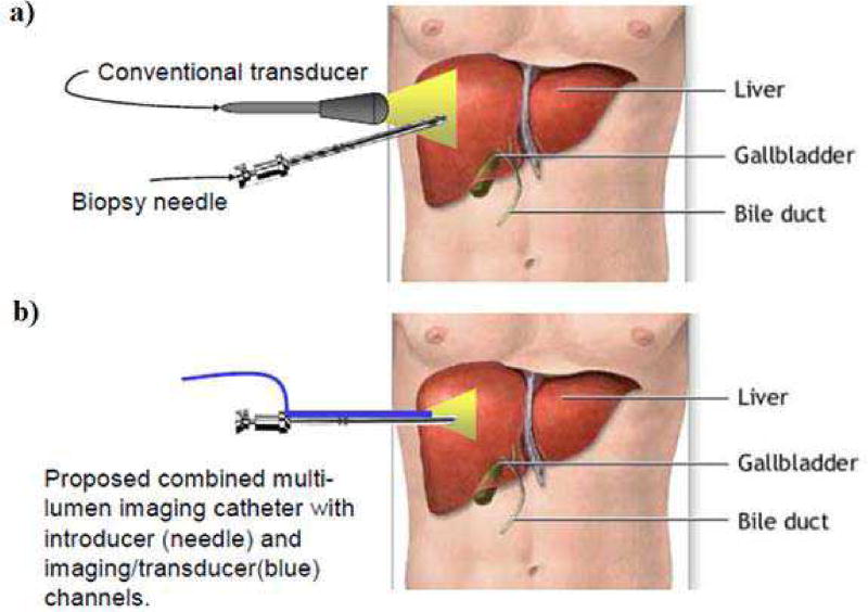
Ultrasound has also been commonly used for intervention guidance. It has the capability to provide anatomical images with reasonable quality in real-time, and together with the advantages including being safe and portable, it has been a popular choice for radiologists. Previous studies have shown that ultrasound guidance can improve the reliability and safety of the interventional procedures, including liver biopsies [11–13] and pericardiocentesis [14, 15]. The drawbacks of ultrasound rise from the compromise between image resolution and penetration depth. Currently, during the guidance procedure, the ultrasound probes are placed at the body surface of the patients, as illustrated in Fig. 1a). In order to visualize organs or structures which are deep inside the body, the center frequency would have to be lowered to increase the penetration depth. This leads to a worsened image resolution, thus decreasing the guidance reliability. Additionally, by using a separate ultrasound probe, very often the operator would be manipulating the intervention device and the probe at the same time, or having another sonographer for assistance [16, 17]. This heavy skill dependency also poses difficulty in this approach.
Fig. 1.
a) An illustration of the current ultrasound intervention guidance, in which the transducer is placed at the body surface; b) An illustration of the proposed device for intervention guidance, in which the transducer is inserted into the body alongside with the needle. (background image taken from www.llu.edu/images)
When compared to the other approaches, ultrasound has the advantages of being able to perform real-time guidance at the bed-side with minimal patient disturbance. However, as discussed, currently it is highly skill-dependent and the image quality still has rooms for improvement. In order to overcome the above limitations, a solution would be placing the ultrasound probe adjacent to the intervention device. Specifically, a multi-lumen device that comprises of an imaging ultrasonic transducer array positioned right next to an interventional device would be inserted into the body, as illustrated in Fig. 1b). This approach has several advantages. First, as the transducer is directly inserted into the body, the required imaging depth would be significantly reduced. Therefore, a higher center frequency can be used for better image quality. Second, the relative position of the intervention device to the transducer is fixed, hence eliminating the need for the operator to manually adjust the probe location for a good visualization of the device.
In order to do so, a miniature ultrasonic transducer must be developed to be fitted into the imaging channel. Precursor devices have been previously reported from our group, but these devices used a low element count [18] or a larger housing diameter [19]. In this work, we are reporting the development of a 20 MHz, 48-element microlinear array with an outer diameter of 3 mm in order to limit the damage of the intervention procedure. To demonstrate the feasibility of this approach, imaging experiment was carried out to evaluate the performance of the developed transducer.
II. Transducer Specifications
A. Transducer Geometry
A 48-element, 20 MHz phased array transducer was designed with the specifications listed in Table 1. The pitch of the array was designed to be λ/2 for the suppression of grating lobes during beam steering. Given the pitch, an element count of 48 was chosen as a compromise between the image quality and the transducer footprint.
TABLE I.
Specifications of the Phased Array
| Center Frequency | 20 MHz |
| Number of elements | 48 |
| Element size | 25 µm × 800 µm |
| Element pitch | 37 µm |
| Element kerf | 12 µm |
| Housing diameter | 4 mm |
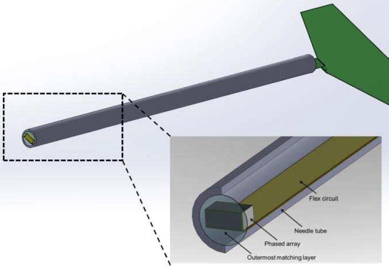
As the transducer would need to be inserted into the body alongside with the interventional device, it has to be housed in a relatively long needle housing to allow more room for operation. The schematic section drawing of the phased array showing all major components are given in Fig. 2. A specially designed long flex circuit was incorporated in this design for the ease of fabrication, of which the details would be given in the following section.
Fig. 2.
The schematic section drawing of the designed phased array transducer. Please note that the housing is designed to have a length of at least 7 cm for the intervention procedure.
B. Transducer Materials
The materials used in building the phased array and their corresponding properties are listed in Table 2 and Table 3. PZT-5H ceramic (C-92H, Fuji Ceramics, Japan) was chosen as the piezoelectric material due to its good balance between performance and fabrication cost-effectiveness. Its fine grain nature also can help alleviate the damage from dicing, which would be necessary for composite fabrication. This is particularly important in this work as the element width would be very small, i.e. 25 µm. The materials used for each layers and their corresponding thicknesses were computed and optimized using the commercial software PiezoCAD (Sonic Concepts Inc., Woodinville, WA), which is based on the KLM model.
TABLE II.
The Materials of the Phased Array
| Layer | Material | Thickness (µm) |
|---|---|---|
| Piezoelectric | PZT-5H (C-92H) | 90 |
| Backing | Epotek 301 | 300001 |
| 1st matching | 2–3 µm silver epoxy2 | 22 |
| 2nd matching | Parylene C | 28 |
. This is approximate number. The whole housing was filled with Epotek 301 up to the end, therefore the backing thickness would be at least 30 mm
. This refers to epoxy with embedded silver particles, with a size of 2 to 3 µm
TABLE III.
Properties of the Transducer Materials
| Materials | c [m/s] |
Z [MRayl] |
kt | k33 | d33 [pC/N] |
Kε |
|---|---|---|---|---|---|---|
| PZT-5H | 4300 | 35 | 0.51 | 0.73 | 770 | 1895 |
| Parylene C | 2350 | 2.6 | - | - | - | - |
| Epotek 301 | 2650 | 3.0 | - | - | - | - |
| Silver-loaded epoxy | 1900 | 7.3 | - | - | - | - |
III. Transducer Fabrication
A. Acoustic Stack Fabrication
The fabrication process of the acoustic stack is illustrated in Fig. 3. First, a 2-2 composite of PZT-5H and Epotek 301 was fabricated. The composite was fabricated using the conventional dice-and-fill approach. The PZT-5H ceramic was first diced with a double pitch (i.e. 74 µm) by a dicing saw (Tcar864-1 dicing saw, Thermocarbon Inc., Casselberry, FL), with a H607RM-T4-010030 electroformed hub-type dicing blade (Asahi Diamond Industrial Co., Ltd., Tokyo, Japan). The blade was dressed in a silicon carbide block so as to reduce the lateral vibration during the dicing process, as excess lateral vibration might cause the collapse of the thin ceramic posts. The dicing depth was chosen to be 150 µm so as to allow more room for the lapping process towards the final thickness of 90 µm.
Fig. 3.
The illustration of the fabrication process for the acoustic stack.
The cuts were then filled with Epotek 301 epoxy. Due to the fine kerf, the piece was cured in a dry nitrogen environment for at least three days before the next step to ensure a proper setting of the epoxy. After removal of the excess epoxy on the surface, the piece was diced the second time to yield the final composite with 37 µm pitch. The cuts were again filled with epoxy and the composite was lapped down to the final thickness (90 µm) after the same curing procedure. The reason for dicing the composite two times was to reduce the chance of pillar breaking. Although C-92H has an average grain size of 3.5 µm, dicing it directly into pillars which are 25 µm wide and 250 µm tall (i.e. aspect ratio of 10) still has a high failure rate.
The top and bottom surfaces of the composite was cleaned and sputtered (NSC-3000, Nano-Master Inc., Austin, TX) with a total of 500/1000 Å Cr/Au as a conduction layer. The first matching layer, which comprises 2–3 µm silver particles (Adrich Chem. Co., Milwaukee, WI) mixed with Insulcast 501 (American Safety Tech. Roseland, NJ) epoxy, was casted on the top surface of the composite. In order to achieve a higher acoustic impedance to better match with the piezoelectric layer [20], the stack was centrifuged with 3000 rpm. It was lapped down to 22 µm after curing in dry nitrogen environment overnight.
On the bottom surface of the composite, individual element electrodes are separated by removing the gold layer on the epoxy. This can be achieved by cleaning the composite surface with acetone. Based on the fact that the electrodes tend to adhere better on the ceramics than on the epoxy, the gold on the epoxy surface would be washed off before those adhered to the ceramic surface, therefore leaving only the electrodes on the elements intact [21]. This process was monitored closely so that it was stopped once the gold on the kerf was washed off, to avoid the removal of electrodes on the element surface.
B. Flexible Circuit Fabrication
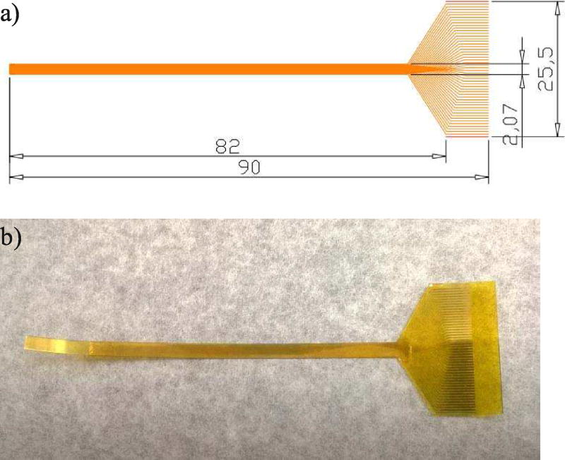
The interconnection between the array elements and the imaging system was facilitated by an intermediate flexible circuit. As discussed, the flexible circuit was specially designed to accommodate for the long needle configuration. Specifically, it has to be longer than the needle housing in order to route the signal out from the long needle housing. The schematic drawing of the flexible circuit is shown in Fig. 4a). The array-end of the circuit consists of a thin and long strip (left part of the circuit), so that it can be housed in the narrow casing. The connector traces are 15 µm wide, with the same pitch as the array (i.e. 37 µm). At the connector side, the traces fan out to a pitch of 500 µm and widen to 300 µm at the same time, in order to cope with the connector specifications.
Fig. 4.
The schematic drawing of the flexible circuit (units are in mm); b) The actual fabricated flexible circuit.
A 25-µm-thick polyimide surface was used as the supporting layer of the flexible circuit. First it was sputtered with 500/2500 Å Cr/Au on top, and the pattern of the traces was created using the photolithography technique. Specifically, the gold sputtered surface was first covered by a thin layer of photoresist. Upon exposure to a pattern of intense light, the exposed part of the photoresist was removed, leaving only certain part of the gold covered. The covered pattern should correspond to the desired traces pattern. The uncovered gold was removed by etching, and the remaining photoresist was also removed, leaving behind the final flexible circuit. After cleaning, another layer of 25-µm-thick polyimide was put on the surface of the circuit, serving as a protective layer. Finally, the circuit was cut out from the whole supporting piece using laser cutting technique (Laserod Inc., Torrance, CA). The finished flexible circuit is shown in Fig. 4b).
C. Transducer Assembly
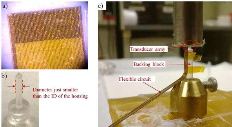
With the acoustic stack and the flexible circuit ready, the final steps would be assembling the components into the designed phased array. First the flexible circuit was placed on the bottom surface of the composite (i.e. the surface with separated electrodes) and carefully aligned with the elements, as shown in Fig. 5a). A small amount of Epotek 301 was applied at the interface and a constant pressure was maintained across the whole assembly for a good bonding. After that it was cured in a dry nitrogen environment for at least 3 days.
Fig. 5.
a) It shows the end of the flexible circuit bonded onto the composite. The traces on the circuit are aligned with the electrodes on the individual elements. b) The backing block made of Epotek 301 is shown. The diameter of the backing block is around 200 µm less than the inner diameter of the housing, so as to ease the positioning of the array at the center of the housing. c) The bonding process of the acoustic stack to the backing block is shown. The array sits at the top of the backing block (inside the red circle), and the flex circuit bends along the side of the backing block.
The assembly was then bonded to a pre-fabricated backing block made of Epotek 301 epoxy, as shown in Fig. 5b). The backing block was made by injecting Epotek 301 into a pre-fabricated RTV mould, and letting it to cure. The diameter of the backing block was slightly smaller than (i.e. 200 µm less) the inner lumen of the housing for the ease of positioning the transducer. Again the acoustic stack (with the flexible circuit) was bonded to the backing block with Epotek 301 as a very thin adhesive layer (shown in Fig. 5c). The flex circuit was bended along the side of the backing block during the bonding process. After curing in the dry nitrogen environment, the finished acoustic stack was encased in a needle housing with an outer diameter of 3 mm. The housing was made of aluminum to provide RF shielding. Finally, 25 µm of Parylene C (Specialty Coating Systems, Indianapolis Inc., IN) was coated on the surface of the transducer for both acoustic matching and electrical insulation. After the prototype was finished, it was poled in air under room temperature for 10 minutes using a dc field of around 3 kV/mm.
D. Signal Routing
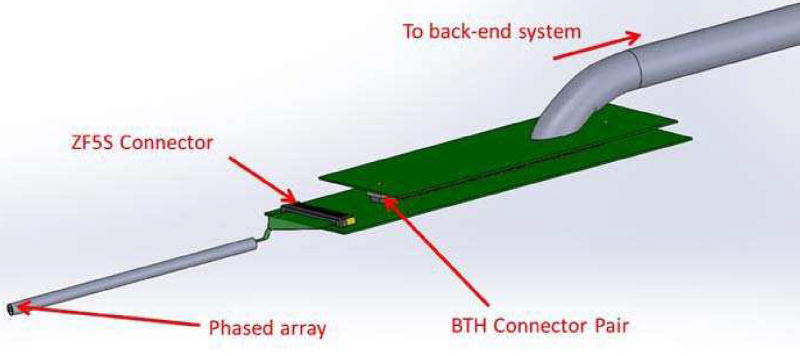
A house-developed imaging system [22] was used as the back-end for the image formation. The signal routing was achieving by an array connector board, and a cable assembly, as illustrated in Fig. 6. The array connector board consists of a ZF5S-50-01-T-WT connector and a BTH-120-01-X-D-A connector (Samtec Inc., New Albany, IN). The flexible circuit on the transducer was directly inserted into the ZF5S-50-01-T-WT (Samtec Inc., New Albany, IN) connector to make the contact connection. Connection between the array connector board and the cable assembly was achieved by the BTH connector pair. The end of the cable assembly was soldered on a satellite board (on the right of Fig. 6), on which the BTH connector resides.
Fig. 6.
An illustration of the signal routing scheme from the phased array transducer to the back-end imaging system. The transducer array was located on the left, and the signals are routed through the flex circuit to a connector board, then to the satellite board of the cable assembly.
IV. Results AND Discussions
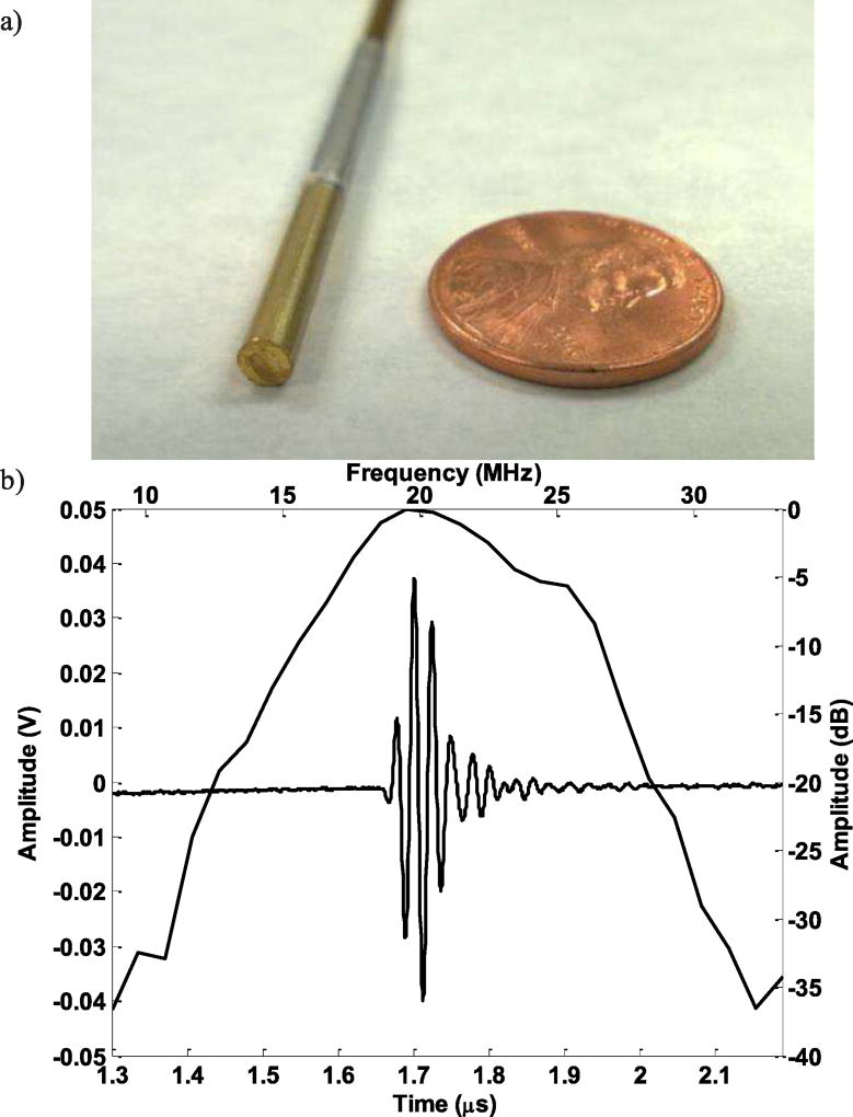
The finished prototype is shown in Fig. 7a). In order to demonstrate the feasibility of this transducer array to be used for intervention guidance, the developed prototype was first characterized using the standard pulse-echo experiment. Then phantom imaging experiments were carried out to quantify the image resolution and to evaluate the performance of the prototype in imaging biological tissue.
Fig. 7.
a) The finished prototype transducer; b) The corresponding pulse-echo experiment results.
A. Transducer Characterization
Pulse-echo responses of the array element were measured. Each element was excited using a Panametrics 5900PR 200-MHz pulser/receiver (Panametrics Inc., Waltham, MA). The transmit energy and receive gain for the Panametrics 5900PR were set at 1 µJ and 20 dB respectively. The transducer was immersed in a deionized water bath, and the echo signal from a quartz plate was then received and recorded using an analog-to-digital CompuScope hardware (CS122G1, Gage Applied Technologies Inc., Montreal, Quebec, Canada) set at 50 Ω coupling. The measured pulse-echo characteristic of a representative element was shown in Fig. 7b). The center frequency is around 20 MHz and the bandwidth is around 42%, which is reasonable for an imaging transducer.
Other than the pulse-echo testing, the combined electrical and mechanical crosstalk was measured between adjacent elements. For this measurement the phased array was placed in a deionized water bath with no reflector. A function generator (AFG 3252, Tektronix Inc., Beaverton, OR) set in sinusoid burst mode was used with amplitude of 5 V peak-to-peak. An element was excited at discrete frequencies from 15 MHz to 25 MHz with a frequency step size of 1 MHz, and the peak applied voltage was recorded. The maximum crosstalk was around −28 dB across the nearest element and −35 dB across the next-nearest element. The average crosstalk values were −32 dB and −39 dB across the nearest and next-nearest element, respectively.
The directivity of this phased array was also evaluated using the hydrophone HPM04/1 (Precision Acoustics, Dorchester, UK). The measured −6dB directivity of the transducer is around ±20°, which is slightly less than the simulated results probably due to crosstalk issue. Therefore we would expect a sensitivity drop when the beam steers over 20°, which would be further evaluated in the imaging experiment.
B. Imaging Experiment
Although the performance of the prototype transducer from the pulse-echo testing suggests that it might be suitable for the proposed application, the ultimate indication would still be its imaging capability. Therefore, imaging experiments were carried out for further evaluation.
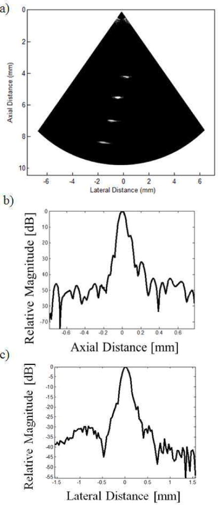
The image resolution of the prototype was evaluated by imaging a wire phantom. The wire phantom comprised of four 20 µm diameter tungsten wires (California Fine Wire Co., Grover Beach, CA), and each wire was positioned at different locations. The axial separation between the wires was around 1.33 mm, and the azimuth separation was around 0.67 mm. With a center frequency of 20 MHz, the corresponding wavelength is 75 µm, thus the 20 µm wires could be safely assumed as four point targets.
The wire phantom image obtained is shown in Fig. 8a). A single transmit focus at 6 mm was achieved by delay-and-sum beamforming, which corresponds to a F-number of around 3.3. On reception, dynamic receive beamforming was employed to form the image. One of the wires was positioned at the focal point in order to obtaining the axial and azimuth line spread functions, as shown in Fig. 8b) and c). It can be seen that the four wires can be visualized clearly with reasonable image quality. No apodization was applied to the aperture during the imaging process, which might be the possible cause for the observed sidelobes.
Fig. 8.
a) The image of the wire phantom with a 30 dB dynamic range. b) The axial line spread function at the focal point. c) The azimuth line spread functions at the focal point.
From the line spread functions, the −6 dB axial and azimuth resolutions were around 80 µm and 210 µm respectively. Besides, from the previous pulse-echo measurement, we can see that the pulse length (PL) of the received echo is approximately 0.1 µs, corresponding to a pulse length of 150 µm. The well-known equations for approximating axial and azimuth resolution are: RA = PL/2 and RL = F# × λ [23], where RA and RL are the axial and azimuth resolution respectively, F# is the F-number and λ is the wavelength. Therefore, the approximate axial and azimuth resolutions of the transducer are 75 µm and 247 µm, which corresponds to our experimental results.
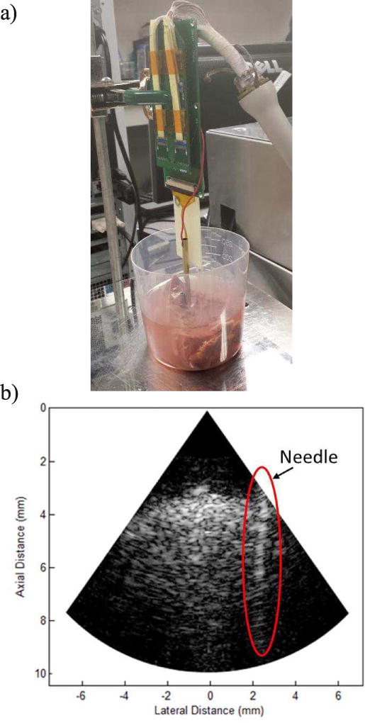
As the phased array is intended to use alongside with an intervention device such as biopsy needle, we have obtained the image of a needle in a biological tissue so as to evaluate the guiding capability of the array. A stainless steel needle with an outer diameter of 3 mm was inserted into a fresh cow liver, mimicking the actual biopsy process.
The experimental setup and the obtained images are shown in Fig. 9. A dynamic range of 45 dB was used for the image. The needle wall could be clearly observed and the wall boundary was well-defined after insertion into the cow liver. The image quality was also reasonable as could be seen from the fine speckle pattern. The penetration depth was around 10 mm, which might be sufficient in some cases, but the compromise between penetration and resolution should be further investigated to find a better balance for this application. Towards the periphery of the image a decrease in signal strength is also observed due to the directivity limitation, but it should be adequate for the current application.
Fig. 9.
a) The experimental setup of the ex vivo imaging experiment. b) The image of the needle inserted in a cow liver.
V. Conclusions
In this paper, we have reported the development of a miniature phased array transducer then can be inserted into the body for interventional guidance. The fabricated 48-element 20 MHz phased array has an outer diameter of 3 mm and shows good pulse-echo characteristics with an acceptable inter-element crosstalk. The ultimate goal of this array is to image small blood vessels and/or pathological tissues inside the patient’s body, increasing the reliability of the guiding process.
Imaging experiments were carried out, and the capability of the phased array in positioning the intervention device was demonstrated. The performance of the proposed phased array transducer demonstrates the feasibility of such an approach for interventional guidance. Further work could be done on optimizing the center frequency used for specific applications, so as to have a better balance between the penetration depth and image resolution.
Acknowledgments
We would like to thank you Dr. Changgeng Liu for his help in fabricating the flexible circuits.
This work is supported by NIH grant P41-EB002182 in part by a STTR subcontract HL93879 from InnoScion LLC.
Biographies
Chi Tat Chiu received his Bachelor degree in Medical Engineering at the University of Hong Kong. He later also pursued a Master degree in Electrical and Electronic Engineering at the University of Hong Kong. In 2016, He received his PhD degree in Biomedical Engineering from the University of Southern California, under the supervisor of Professor Kirk K. Shung. His research interests include the development of high frequency ultrasonic transducer arrays, and back-end signal processing including beamforming and flow imaging.

Bong Jin Kang received his M.S. degrees in Electrical Engineering and Biomedical Engineering from University of Southern California, Los Angeles, CA, USA, in 2008 and 2010, respectively, and his Ph.D. degree in Biomedical Engineering from University of Southern California, Los Angeles, CA, in 2015. From 2015 to 2016, he pursued post-doctoral research at the NIH Resource Center for Medical Ultrasonic Transducer technology, Department of Biomedical Engineering, University of Southern California, Los Angeles, CA. His research interest includes high frequency array-based ultrasound imaging system for small animal imaging.
Payam Eliahoo is pursuing the Ph.D. degree at the University of Southern California, Los Angeles, CA, USA. He is a member of the Ultrasound Transducer Resource Center (UTRC), Los Angeles, CA, USA. His research interests include high-frequency ultrasound imaging array electronics development.

K. Kirk Shung obtained a B.S. in EE from Cheng Kung University, Taiwan in 1968 and a Ph.D. in EE from University of Washington, Seattle, WA, in 1975. He has been a professor of biomedical engineering at USC since 2002 and the director of NIH Resource Center on Medical Ultrasonic Transducer Technology since 1997. He was appointed a dean’s professor in biomedical engineering, an endowed position, at the Viterbi School of Engineering of USC in 2013.
Dr. Shung is a life fellow of IEEE, and a fellow of American Institute of Ultrasound in Medicine. He is a founding fellow of American Institute of Medical and Biological Engineering. He received the IEEE Engineering in Medicine and Biology Society Early Career Award in 1985 and was the coauthor of a paper that received the best paper award for IEEE Transactions on Ultrasonics, Ferroelectrics and Frequency Control (UFFC) in 2000. He was elected an outstanding alumnus of Cheng-Kung University in Taiwan in 2001. He was selected as the distinguished lecturer for the IEEE UFFC society for 2002–2003. He received the Holmes Pioneer Award in Basic Science from American Institute of Ultrasound in Medicine in 2010. He received the academic career achievement award from the IEEE Engineering in Medicine and Biology Society in 2011 and IEEE Biomedical Engineering Award in 2016. Dr. Shung has published more than 500 papers and book chapters. He is an associate editor of IEEE Transactions on Ultrasonics, Ferroeelctrics and Frequency Control, IEEE Transactions on Biomedical Engineering and Medical Physics. Dr. Shung’s research interest is in ultrasonic transducers, high frequency ultrasonic imaging and ultrasound microbeam.
Contributor Information
Chi Tat Chiu, Department of Biomedical Engineering, University of Southern California, Los Angeles, CA.
Bongjin Kang, Department of Biomedical Engineering, University of Southern California, Los Angeles, CA.
Payam Eliahoo, Department of Biomedical Engineering, University of Southern California, Los Angeles, CA.
Abraham Theodore, InnoScion LLC, Baltimore, MD.
K. Kirk Shung, Department of Biomedical Engineering, University of Southern California, Los Angeles, CA.
References
- 1.Skolnick M. The role of sonography in the placement and management of jugular and subclavian central venous catheters. AJR. American journal of roentgenology. 1994;163:291–295. doi: 10.2214/ajr.163.2.8037017. [DOI] [PubMed] [Google Scholar]
- 2.Lameris J, Post P, Zonderland H, Gerritsen P, Kappers-Klunne M, Schütte H. Percutaneous Placement of Hickman Catheters: Comparison of Sonographically Guided and Blind Techniques. AJR. American journal of roentgenology. 1990;155:1097–1099. doi: 10.2214/ajr.155.5.2120941. [DOI] [PubMed] [Google Scholar]
- 3.Rimondi E, et al. Percutaneous CT-guided biopsy of the spine: results of 430 biopsies. European Spine Journal. 2008;17.7:975–981. doi: 10.1007/s00586-008-0678-x. [DOI] [PMC free article] [PubMed] [Google Scholar]
- 4.Espinosa Leandro A, et al. CT-guided biopsy of bone: a radiologist’s perspective. American Journal of Roentgenology. 2008;190.5:W283–W289. doi: 10.2214/AJR.07.3138. [DOI] [PubMed] [Google Scholar]
- 5.Li Y, et al. CT-guided percutaneous core needle biopsy for small (≤ 20 mm) pulmonary lesions. Clinical Radiology. 2013;68(1):e43–e48. doi: 10.1016/j.crad.2012.09.008. [DOI] [PubMed] [Google Scholar]
- 6.Anastasiadis AG, Lichy MP, Nagele U, Kuczyk MA, Merseburger AS, Hennenlotter J, et al. MRI-guided biopsy of the prostate increases diagnostic performance in men with elevated or increasing PSA levels after previous negative TRUS biopsies. European Urology. 2006;50:738–749. doi: 10.1016/j.eururo.2006.03.007. [DOI] [PubMed] [Google Scholar]
- 7.Liberman L, Bracero N, Morris E, Thornton C, Dershaw DD. MRI-guided 9-gauge vacuum-assisted breast biopsy: initial clinical experience. American Journal of Roentgenology. 2005;185:183–193. doi: 10.2214/ajr.185.1.01850183. [DOI] [PubMed] [Google Scholar]
- 8.Uecker M, Zhang S, Voit D, Karaus A, Merboldt KD, Frahm J. Real-time MRI at a resolution of 20 ms. NMR in Biomedicine. 2010;23:986–994. doi: 10.1002/nbm.1585. [DOI] [PubMed] [Google Scholar]
- 9.Uecker M, Zhang S, Voit D, Merboldt K-D, Frahm J. Real-time MRI: Recent Advances using Radial FLASH. Imaging. 2012;4:461–476. [Google Scholar]
- 10.Xu S, Kruecker J, Turkbey B, Glossop N, Singh AK, Choyke P, et al. Real-time MRI-TRUS fusion for guidance of targeted prostate biopsies. Computer Aided Surgery. 2008;13:255–264. doi: 10.1080/10929080802364645. [DOI] [PMC free article] [PubMed] [Google Scholar]
- 11.Farrell RJ, Smiddy PF, Pilkington RM, Tobin AA, Mooney EE, Temperley IJ, et al. Guided versus blind liver biopsy for chronic Hepatitis C: clinical benefits and costs. Journal of hepatology. 1999;30:580–587. doi: 10.1016/s0168-8278(99)80187-1. [DOI] [PubMed] [Google Scholar]
- 12.Kerwin SC. Hepatic aspiration and biopsy techniques. Veterinary Clinics of North America: Small Animal Practice. 1995;25:275–291. doi: 10.1016/s0195-5616(95)50027-0. [DOI] [PubMed] [Google Scholar]
- 13.Sparchez Z, et al. Usefulness of contrast enhanced ultrasound guidance in percutaneous biopsies of liver tumors. Journal of Gastrointestinal and Liver Disease. 2011;20(2):191–196. [PubMed] [Google Scholar]
- 14.Tsang TS, Freeman WK, Sinak LJ, Seward JB. Echocardiographically guided pericardiocentesis: evolution and state-of-the-art technique. Mayo Clinic Proceedings. 1998:647–652. doi: 10.1016/S0025-6196(11)64888-X. [DOI] [PubMed] [Google Scholar]
- 15.Tsang TS, El-Najdawi EK, Seward JB, Hagler DJ, Freeman WK, O’Leary PW. Percutaneous echocardiographically guided pericardiocentesis in pediatric patients: evaluation of safety and efficacy. Journal of the American Society of Echocardiography. 1998;11:1072–1077. doi: 10.1016/s0894-7317(98)70159-2. [DOI] [PubMed] [Google Scholar]
- 16.Tang S, Li JH, Lui SL, Chan TM, Cheng IKP, Lai KN. Free-hand, ultrasound-guided percutaneous renal biopsy: experience from a single operator. European journal of radiology. 2002;41:65–69. doi: 10.1016/s0720-048x(01)00439-9. [DOI] [PubMed] [Google Scholar]
- 17.Nyland TG, Mattoon JS, Herrgesell E, Wisner E. Ultrasound-guided Biopsy. Small animal diagnostic ultrasound. 2002:30–48. [Google Scholar]
- 18.Stephens DN, O’Donnell M, Thomenius KE, Dentinger A, Wildes D, Chen P, Shung KK, Cannata J, Khuri-Yakub PT, Oralkan O, Mahajan A, Shivkumar K, Sahn DJ. Experimental studies with a 9f forward-looking intracardiac imaging and ablation catheter. Journal of Ultrasound in Medicine. 2009;28(2):207–215. doi: 10.7863/jum.2009.28.2.207. [DOI] [PMC free article] [PubMed] [Google Scholar]
- 19.Chiu CT, Williams JA, Kang BJ, Abraham T, Shung KK, Kim HH. Fabrication and characterization of a 20 MHz microlinear phased array transducer for intervention guidance. Ultrasonics Symposium. 2014:2121–2124. doi: 10.1109/TUFFC.2017.2709623. [DOI] [PMC free article] [PubMed] [Google Scholar]
- 20.Ritter T, Shung K, Tutwiler R, Shrout T. Medical imaging arrays for frequencies above 25 MHz. Ultrasonics Symposium. 1999:1203–1207. [Google Scholar]
- 21.Chabok HR, Cannata JM, Kim HH, Williams JA, Park J, Shung KK. A high-frequency annular-array transducer using an interdigital bonded 1–3 composite. IEEE Transactions on Ultrasonics, Ferroelectrics and Frequency Control. 2011;58(1):206–214. doi: 10.1109/TUFFC.2011.1787. [DOI] [PMC free article] [PubMed] [Google Scholar]
- 22.Hu C, Zhang L, Cannata JM, Yen J, Shung KK. Development of a 64 channel ultrasonic high frequency linear array imaging system. Ultrasonics. 2011;51:953–959. doi: 10.1016/j.ultras.2011.05.010. [DOI] [PMC free article] [PubMed] [Google Scholar]
- 23.Shung KK. Diagnostic ultrasound: Imaging and blood flow measurements. CRC press; 2015. [Google Scholar]


