Significance
Dye-sensitized photoelectrosynthesis cells (DSPECs) provide a basis for artificial photosynthesis and solar fuels production. By combining molecular chromophores and catalysts with high surface area, transparent semiconductor electrodes, a DSPEC provides the basis for light-driven conversion of water to O2 and H2 or for reduction of CO2 to carbon-based fuels. The incorporation of plasmonic cubic silver nanoparticles, with a strongly localized surface plasmon absorbance near 450 nm, to a DSPEC photoanode induces a great increase in the efficiency of water oxidation to O2 at a DSPEC photoanode. The improvement in performance by the molecular components in the photoanode highlights a remarkable advantage for the plasmonic effect in driving the 4e-/4H+ oxidation of water to O2 in the photoanode.
Keywords: water oxidation, DSPEC, core/shell, plasmonic, atomic layer deposition
Abstract
Dye-sensitized photoelectrosynthesis cells (DSPECs) provide a flexible approach for solar water splitting based on the integration of molecular light absorption and catalysis on oxide electrodes. Recent advances in this area, including the use of core/shell oxide interfacial structures and surface stabilization by atomic layer deposition, have led to improved charge-separation lifetimes and the ability to obtain substantially improved photocurrent densities. Here, we investigate the introduction of Ag nanoparticles into the core/shell structure and report that they greatly enhance light-driven water oxidation at a DSPEC photoanode. Under 1-sun illumination, Ag nanoparticle electrodes achieved high photocurrent densities, surpassing 2 mA cm−2 with an incident photon-to-current efficiency of 31.8% under 450-nm illumination.
A dye-sensitized photoelectrosynthesis cell (DSPEC) integrates light absorption and catalysis to carry out the oxidation of water coupled to the production of H2 or reduced carbon products. The photoanode of a DSPEC uses a wide-bandgap semiconductor, typically TiO2 or SnO2, as a high surface area scaffold for immobilizing molecular chromophores and catalysts. This approach establishes an interface capable of supporting light-driven charge separation and subsequent catalysis at the electrode surface (1–3).
Recent progress has been made in improving solar conversion efficiencies in DSPEC devices, especially by introducing ITO/TiO2 and SnO2/TiO2 core/shell (ITO = tin-doped indium oxide)-based photoanodes (4–6). Even with the core/shell enhancements, additional increases in efficiency and durability are needed to make DSPEC technology viable. Key factors influencing the efficiency of a DSPEC photoanode include the fraction of light absorbed, the interfacial dynamics leading to the accumulation of multiple oxidative equivalents at a catalyst, and the rate of catalysis for water oxidation at the photoanode (7).
The influence of surface-immobilized Ag or Au nanoparticles on the solar conversion efficiencies of dye-sensitized solar cells (DSSCs) by plasmon-enhanced light absorption has been documented (8–11). The introduction of metallic nanoparticles in a DSSC or related photovoltaic device can influence the photoconversion efficiency in several ways, including near-field coupling of the surface plasmon with the light-absorbing material (9, 10, 12), increasing the optical pathlength through the dye layer by light scattering (13, 14), or by electronic effects arising from the presence of the metal nanoparticles (8). In this work, we incorporate ∼100-nm cubic Ag nanoparticles (Ag NPs) on the surface of FTO|SnO2/TiO2 films (FTO = fluorine-doped tin oxide) containing a molecular dye/catalyst surface monolayer and observe a substantial improvement in the photocurrent response of the photoanode. Based on the available evidence, we propose that the improved photocurrent density arises from light capture and concentration by the Ag NPs and their role in enhancing the rate of excitation by dyes lying in close proximity.
The application of surface plasmon near-field enhancement is used here to improve the performance of a dye-sensitized photoanode for carrying out light-driven water oxidation at a photoanode, Eq. 1.
| [1] |
The approach that we have taken involves incorporation of cubic silver NPs onto a FTO|SnO2/TiO2 core–shell mesoporous surface. Silver has proven to be an optimal metal for supporting strong surface plasmons in visible wavelengths due to its low dielectric function, and therefore high quality factor (>10), over this range of the spectrum (15). To protect the Ag NPs from degradation by exposure to solution (16), the Ag NPs were deposited on the SnO2 surface before forming the TiO2 shell by atomic layer deposition.
Our experiments show that incorporating Ag NPs significantly enhances the performance of the DSPEC photoanode in comparison with a similarly prepared photoanode without the Ag NPs. The improved performance entailed higher photocurrent densities, above 2 mA cm−2 under 1-sun irradiation, without any loss in the faradaic efficiencies for O2 generation (∼95%). An improved incident photon-to-current efficiency (IPCE) of 31.8% at 450 nm compared with 16.3% of photoanode without Ag NPs was observed for the Ag NP surface.
Results and Discussion
Photoanode Preparation and Characterization.
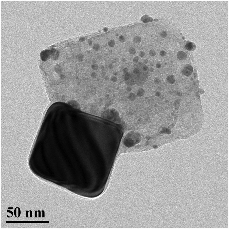
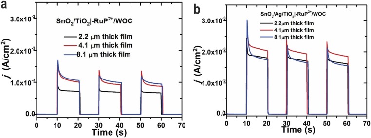
Mesoporous FTO|SnO2/TiO2 core–shell electrodes used in this study were prepared as described elsewhere (4). Fig. S1 shows the image of 3.0-nm TiO2 shell coating Ag particles. Different mesoporous layer thicknesses of 2.2, 4.1, and 8.1 µm were investigated. The effect of oxide layer thickness on the performance of the interface is shown in Fig. S2. As the 4.1-µm electrode gave the highest photocurrent response, the majority of experiments in this study were carried out with ∼4-µm mesoporous electrodes.
Fig. S1.
Transmission electron microscope image of a cubic Ag NP coated with a 3.0-nm TiO2 shell deposited by ALD.
Fig. S2.
(A) Current vs. time measurements as a function of the SnO2 film thickness for FTO|SnO2/TiO2|–RuP2+/WOC with (black) 2.2 µm, (red) 4.1 µm, or (blue) 8.1 µm films. (B) Current vs. time measurements as a function of SnO2 film thickness for FTO|SnO2/AgNP/TiO2|–RuP2+/WOC with (black) 2.2 µm, (red) 4.1 µm, or (blue) 8.1 µm films. The measurements were taken with an applied bias of 0.2 V vs. Ag/AgCl in 0.1 M HAc/Ac− buffer at pH 4.65 with 0.4 M NaClO4. Beginning in the dark,100-mW cm−2 illumination was applied to the electrodes in 10-s intervals.
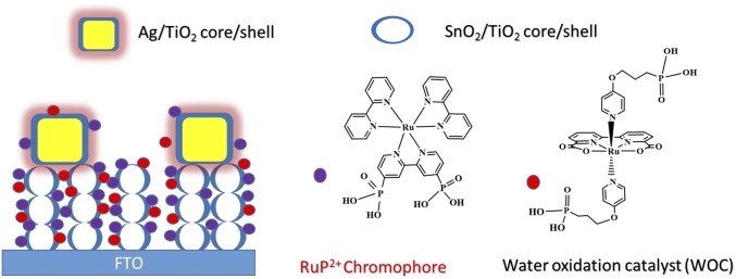
The deposition of polyvinylpyrrolidone (PVP)-coated Ag NPs on the SnO2 film was accomplished by an electrostatic interaction mechanism (9, 17). Briefly, this involved a short dip treatment of the FTO|SnO2 electrode in piranha solution (3:1 H2SO4:H2O2), rinsing with deionized water, and then an overnight soak of the electrode in an ethanol solution with 0.05 wt % Ag NPs. After soaking in the Ag NP solution, the electrodes were air dried and underwent atomic layer deposition (ALD) to deposit the TiO2 shell. This gave the complete FTO|SnO2/AgNP/TiO2| core/shell surface. The as-prepared electrodes were immersed in methanol solution containing 2 mM [Ru(4,4′-PO3H2-bpy)(4,4′-bpy)2]2+ (RuP2+; bpy = 2,2′-bipyridine). After surface adsorption of the RuP2+ chromophore, the water oxidation catalyst [Ru(bda)(4-O(CH2)3P(O3H2))-pyr)2] (WOC; pyr = pyridine; bda = 2,2′-bipyridine-6,6′-dicarboxylate) was incorporated onto the surface during a second soaking step in methanol solution containing 1 mM of the complex. Previous work demonstrated that the loading of the RuP2+ chromophore on the surface does not preclude the adsorption of the catalyst containing the –(CH2)3-PO3H2 axial anchoring group (18). Fig. 1 illustrates the fully assembled electrode interface, FTO|SnO2/AgNP/TiO2|–RuP2+/WOC. As shown previously by UV-visible measurements, these conditions result in a surface layer consisting of 2:1 chromophore:catalyst ratio (18).
Fig. 1.
Illustration of the electrode surface following deposition of cubic Ag NPs on a SnO2/TiO2 core/shell surface and loading of the RuP2+ chromophore and WOC catalyst to give the FTO|SnO2/AgNP/TiO2|–RuP2+/WOC assembly. (Right) The structures of the RuP2+ chromophore and WOC catalyst are shown.
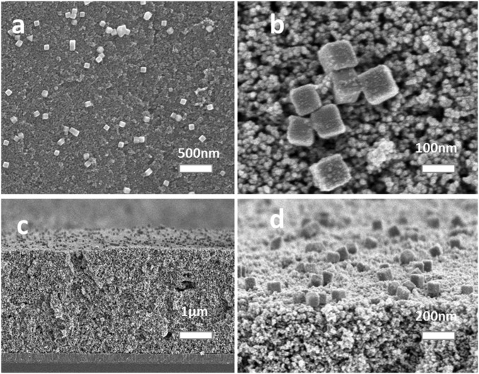
Fig. 2 shows SEM images of the fully prepared FTO|SnO2/AgNP/TiO2|–RuP2+/WOC surface. The 100-nm cubic Ag NPs deposit on the outer surface of the oxide layer, and, as they are larger than the pore openings in the film, it is unlikely that they penetrate within the interior of the film. The 100-nm cubic Ag NPs are randomly dispersed across the top of the oxide layer with both isolated particles and clusters of particles observed. Based on the SEM images, the procedure for depositing the Ag NPs does result in a relatively even distribution across the entire surface.
Fig. 2.
SEM images of the fully formed photoanode surface. (A) Top view of the FTO|SnO2/AgNP/TiO2|–RuP2+/WOC film. The Ag NPs are randomly arranged on the oxide surface and do not permeate into the interior of the film. (B) Magnified view of A. (C) Cross-sectional view of the same electrode. (D) A 45° angle edge-on-view of the surface.
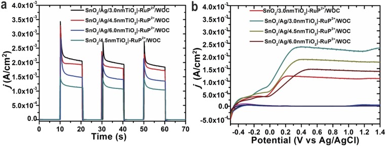
As mentioned above, treatment of the surface by ALD simultaneously forms a TiO2 coating on the Ag NPs and forms the SnO2/TiO2 core/shell surface in the underlying oxide film. The TiO2 coating prevents direct contact of the Ag surface with solution (9, 19). The thickness of the TiO2 surface layer was controlled by varying the number of deposition cycles with each cycle estimated to add 0.06 nm in thickness (20). As summarized in Fig. S3, different thicknesses of the TiO2 layer (3.0, 4.5, and 6.0 nm) were explored with the best photocurrent response observed with the 3.0-nm coating. Unless otherwise noted, all samples were prepared with a 3.0-nm TiO2 shell coating by ALD.
Fig. S3.
(A) Current−time traces over 10-s dark−light cycles for FTO|SnO2/AgNP/TiO2|–RuP2+/WOC electrodes as a function of TiO2 shell thickness at an applied bias of 0.2 V vs. Ag/AgCl, and (B) current density vs. applied voltage under light and dark conditions in 0.1 M acetic acid/acetate buffer at pH 4.65, 0.4 M in NaClO4. The illumination intensity used was 100 mW cm−2 white light with a 400-nm cutoff filter. All scans were performed at a scan rate of 50 mV/s.
Photochemical Studies.
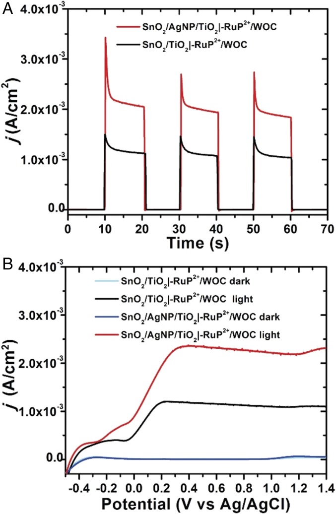
Photocurrent vs. time measurements for FTO|SnO2/AgNP/TiO2|–RuP2+/WOC and FTO|SnO2/TiO2|–RuP2+/WOC electrodes in pH 4.65 acetate buffer (0.1 M HAc/Ac−) with 0.4 M NaClO4 as supporting electrolyte were performed under a 0.2 V vs. Ag/AgCl bias with a Pt mesh counter electrode (Fig. 3). All measurements were performed with 100-mW cm−2 white light (1 sun) irradiation with a 400-nm cutoff filter to avoid direct bandgap excitation of the oxide. The effect of Ag NPs on the photocurrent is apparent in Fig. 3A with nearly a doubling in the current during illumination with the Ag NPs as compared without. In Fig. 3B, the overall form of the current–voltage response with or without the Ag NPs is similar but with higher currents from the electrode with added NPs. Importantly, the point of zero current occurs at a similar voltage in both samples, indicating that charging effects of the metal NPs do not contribute to the improved current response (8).
Fig. 3.
(A) Current−time traces over 10-s dark−light cycles for FTO|SnO2/TiO2|–RuP2+/WOC and FTO|SnO2/AgNP/TiO2|–RuP2+/WOC electrodes at an applied bias of 0.2 V vs. Ag/AgCl. (B) Current density vs. applied voltage curves for the same electrodes under light and dark conditions. White-light illumination at an intensity of 100 mW cm−2 was used with a 400-nm cutoff filter. All scans were performed at a scan rate of 50 mV/s. The experiments were carried out in 0.1 M acetic acid/acetate buffer at pH 4.65, 0.4 M in NaClO4.
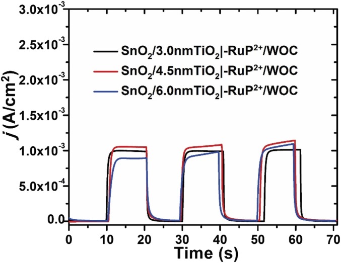
The localized surface plasmon of the Ag NP extends only tens of nanometers from the particle surface and therefore only assemblies at the top of the film, near the Ag NP layer, likely contribute to the improved photocurrent generation (15, 21). Consistent with the localized effect of the plasmon, lower photocurrents were obtained with increasing thickness of the TiO2 layer applied by ALD. Fig. S3 shows the current response with varying TiO2 shell thicknesses of 3, 4.5, and 6 nm. The best performance was achieved with a 3-nm TiO2 coating. Samples prepared with varying thicknesses of the TiO2 shell, but without the inclusion of Ag NPs, showed little difference in the maximum photocurrent density (Fig. S4).
Fig. S4.
Photocurrent density vs. time experiments over 10-s dark–light cycles with SnO2/TiO2 films of different TiO2 shell thicknesses and no added Ag NPs. The current−time traces are for (black) FTO|SnO2/TiO2(3 nm)|–RuP2+/WOC, (red) FTO|SnO2/TiO2(4.5 nm)|–RuP2+/WOC, (blue) FTO|SnO2/TiO2(6 nm)|–RuP2+/WOC at an applied bias of 0.2 V vs. Ag/AgCl in 0.1 M HAC/Ac− buffer at pH 4.65 in 0.4 M NaClO4. The illumination intensity was 100 mW cm−2 generated by a white-light source with a 400-nm cutoff filter.
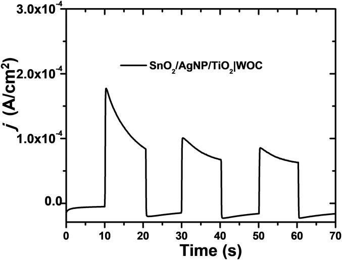
To assess possible photocurrent generation from the Ag NPs alone, Fig. S5 shows photocurrent measurements for FTO|SnO2/AgNP/TiO2|–WOC with no surface-bound chromophore. Without the chromophore, a modest photocurrent of 60 µA cm−2 is produced. This indicates that the enhanced photocurrent observed with FTO|SnO2/AgNP/TiO2|–RuP2+/WOC is not a result of direct light absorption and sensitization by the Ag NPs. Similar to improvements observed in the performance of DSSCs by the incorporation of Au and Ag NPs, the localized surface plasmon of the Ag NPs improves the rate of excitation of RuP2+ chromophores near the NP and leads to higher sustained photocurrents compared with the DSPEC without the Ag NPs (8, 10, 11).
Fig. S5.
Photocurrent density vs. time plot during 10-s dark–light cycles for the chromophore-free assembly FTO|SnO2/AgNP/TiO2|–WOC at an applied bias of 0.2 V vs. Ag/AgCl in 0.1 M HAc/Ac− buffer at pH 4.65 in 0.4 M NaClO4. The illumination intensity was 100 mW cm−2 generated by a white-light source with a 400-nm cutoff filter.
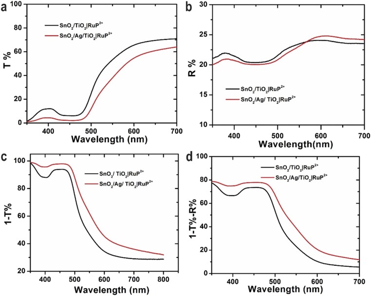
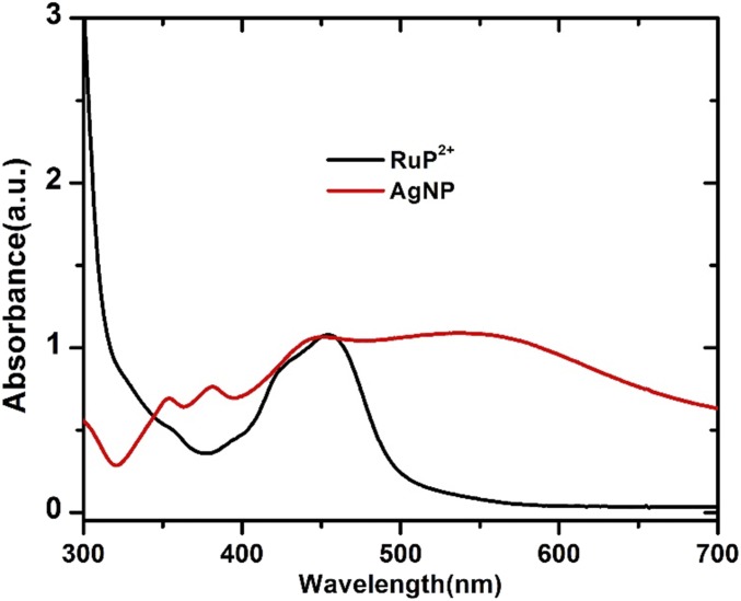
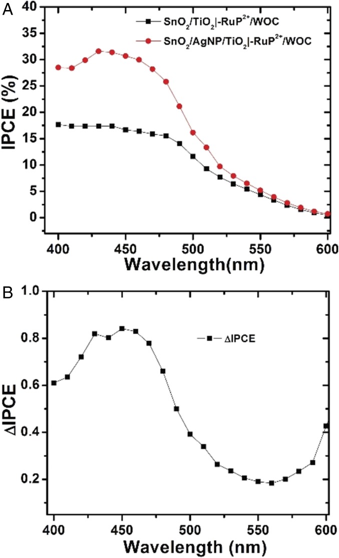
Optical characterization of FTO|SnO2/AgNP/TiO2|–RuP2+/WOC and FTO|SnO2/TiO2|–RuP2+/WOC electrodes including transmittance, reflectance, and absorptance measurements is shown in Fig. S6. It is notable that the plasmon absorbance of the Ag NP overlaps with the λmax = 450 nm metal-to-ligand charge-transfer (MLCT) absorption band for RuP2+ as shown in Fig. S7. This spectral overlap between the chromophore and plasmon resonance of the Ag NP is essential to realizing the improved solar energy conversion of the interface. The IPCE measurements in Fig. 4 highlight the improved light harvesting with the incorporation of the Ag NPs. The IPCE of FTO|SnO2/AgNP/TiO2|–RuP2+/WOC reaches 31.8% at 450 nm, a nearly 100% increase over the IPCE for FTO|SnO2/TiO2|–RuP2+/WOC (16.3%) at this same wavelength. The difference spectrum comparing the IPCE with the Ag NPs minus the IPCE without the Ag NPs is shown in Fig. 4B. From these data, improved light harvesting of the surface with the Ag NPs occurs over wavelengths corresponding to the MLCT excitation of RuP2+. This reiterates that the increased photocurrents are a result of improved light capture by the chromophore through interaction with the surface plasmon of the Ag NP as opposed to a direct effect of the Ag NP. The IPCE value for FTO|SnO2/AgNP/TiO2|–RuP2+/WOC represents one of the highest yet observed for a RuP2+-based DSPEC at 450 nm (4, 22, 23).
Fig. S6.
Optical characterization of (black) FTO|SnO2/TiO2|–RuP2+ and (red) FTO|SnO2/AgNP/TiO2|–RuP2+: (A) transmittance spectra; (B) reflectance spectra (diffuse and specular); (C) adsorptance plus scattering spectra (A + S = 1 − T%) spectra; and (D) adsorptance spectra (A = 1 − T% − R%).
Fig. S7.
Optical characterization of (black) [RuP]2+ in methanol solution and (red) AgNP in the ethanol solution.
Fig. 4.
(A) IPCE plots for FTO|SnO2/TiO2|–RuP2+/WOC and FTO|SnO2/AgNP/TiO2|–RuP2+/WOC. (B) The difference in IPCE (ΔIPCE = IPCE with Ag NP minus IPCE without Ag NP) between the two electrodes.
Light-Driven Water Oxidation.
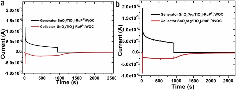
A collector-generator method (24) was used to investigate light-driven O2 production as shown in Fig. S8. These studies revealed essentially the same faradaic efficiency for O2 production by FTO|SnO2/TiO2|–RuP2+/WOC and FTO|SnO2/AgNP/TiO2|–RuP2+/WOC electrodes (96% and 94%, respectively). During 15-min illumination periods, the photocurrent of both FTO|SnO2/TiO2|–RuP2+/WOC and FTO|SnO2/AgNP/TiO2|–RuP2+/WOC decreased to half of their initial values. This result is consistent with previous observations using similar chromophore/catalyst interfaces, and the presence of the Ag NP does not appear to influence the surface stability of the film (4). The high faradaic efficiency for O2 generation with or without the Ag NPs indicates the presence of the metal NPs does not affect the functionality of the catalyst. The substantially higher photocurrents with added Ag NPs are consistent with a plasmon enhancement of chromophores near the NPs, which likely enables higher turnover frequencies of nearby catalysts enabling the higher current densities.
Fig. S8.
Collector–generator measurements for determining the faradaic efficiency of O2 production for (A) FTO|SnO2/TiO2|–RuP2+/WOC and (B) FTO|SnO2/AgNP/TiO2|–RuP2+/WOC. The measurements were performed using a 0.4-cm2 active area with 100-mW cm−2 white light with a 400-nm cutoff filter. The samples were illuminated from 30 to 930 s with a bias of 0.2 V vs. Ag/AgCl. The black trace shows the current measured at the photoanode (generator) and red trace the current measured at the FTO collector. The experiments were performed in 0.1 M HAc/Ac− buffer at pH 4.65 in 0.4 M NaClO4 with a bias of −0.85 V vs. Ag/AgCl applied to the collector.
Transient Absorption Studies.
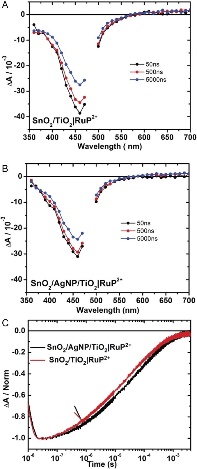
The results of transient absorption (TA) measurements were used to investigate interfacial electron transfer dynamics. The TA measurements were performed under an applied bias of 0.2 V vs. Ag/AgCl at pH 4.65 in 0.1 M acetate buffer 0.4 M in NaClO4. Difference spectra for FTO|SnO2/TiO2|–RuP2+ and FTO|SnO2/AgNP/TiO2|–RuP2+ from 350 to 700 nm following excitation at 532 nm are shown in Fig. 5 A and B. In both Fig. 5 A and B, the spectra are consistent with excitation followed by rapid, <10-ns injection to give the oxidized chromophore, –RuP3+. With or without the presence of the Ag NPs, rapid loss of the characteristic MLCT absorption at λmax = 450 nm evidences the loss of ground state and formation of the oxidized dye.
Fig. 5.
Nanosecond TA difference spectra recorded following excitation at 532 nm for (A) FTO|SnO2/TiO2|–RuP2+ and (B) FTO|SnO2/AgNP/TiO2|–RuP2+ electrodes. The data in A and B were recorded in 0.1 M HAc/Ac− buffer with 0.4 M NaClO4 under an applied bias of 0.2 V vs. Ag/AgCl at room temperature. (C) Single-wavelength TA traces at 460 nm for FTO|SnO2/AgNP/TiO2|–RuP2+ (black) and FTO|SnO2/TiO2|–RuP2+ (red) recorded in 0.1 M HAc/Ac− with 0.4 M NaClO4.
The bleaching recovery traces shown in Fig. 5C reveal similar lifetimes for photooxidized RuP3+ in the presence or absence of the Ag NPs, 25 and 16 μs, respectively, as measured by the time required for half of the absorption feature to decay to zero. Based on the similar lifetime data, the presence of the Ag NPs does not appear to affect either the sensitization of the oxide by RuP2+* or the recombination of injected electrons to the oxidized RuP3+. While not offering direct evidence, taken in concert with the decrease in transmittance (Fig. S6A) and increase in absorptance (Fig. S6D), these observations do support the conclusion that the Ag NPs contribute to the improved performance by plasmon-enhanced light absorption of the RuP2+ sensitizer.
Conclusion.
Our results are consistent with localized surface plasmon-enhanced light harvesting by including Ag NPs in the DSPEC photoanode surface. From the photocurrent and TA measurements, photoinduced electron injection and back-electron transfer are unaffected by the presence of the Ag NPs. However, the introduction of the Ag NPs leads to a nearly twofold increase in the photocurrent generated by the interface under identical conditions. Our results are important in understanding and extending the plasmonic enhancement of molecular light absorption to DSPEC water oxidation applications. The Ag NPs show no detrimental effect on the DSPEC device stability or faradaic efficiency for light-driven water oxidation. The addition of Ag NPs enhances light absorption of the MLCT RuP2+ dye and leads to an increase in the IPCE with a maximum of 31.8% at 450 nm. The plasmonic DSPEC produces a photocurrent density above 2 mA cm−2 after 30 s of illumination with 1 sun simulated solar light. At the microscopic level, the impact of the plasmonic effect is extraordinary. Additional improvements in light collection maybe possible by varying the surface architectures to integrate a greater population of immobilized RuP2+ sensitizers in close proximity to the Ag NPs.
Experimental Details
RuP2+ and WOC were synthesized as previously described (25). FTO was purchased from Hartford Glass with a sheet resistance of 15 Ω/sq. ALD was performed by using a Cambridge NanoTech Savannah S200 instrument with [tetrakis(dimethylamino)titanium] precursor. It is estimated that each cycle of ALD deposits 0.06 nm of TiO2 based on ellipsometry measurements performed on a witness silicon wafer.
Electrochemical and photoelectrochemical experiments were performed using either a CH Instruments 660D potentiostat or a CH Instruments 760E bipotentiostat. A Thor Labs HPLS 30–04 light source was used to provide white-light illumination. For all indicated experiments using 100-mW cm−2 white-light illumination, the electrochemical cell was positioned an appropriate distance from the light source to receive the indicated light intensity as measured with a photodiode (Newport). A 400-nm cutoff filter (Newport) was used to prevent direct bandgap excitation of the semiconductor layer.
PVP-coated cubic Ag NPs were purchased from the Nanocomposix company. Consistent with previous results, the conditions used for the preparation of FTO|SnO2/TiO2|–RuP2+ films result in closely packed monolayers.
UV-Vis Spectroscopy
Samples for optical measurements were fabricated in the same way as described above. A Carry 5000 with an integrating sphere accessory was used to determine the absorptance of the [RuP]2+ loaded slides.
IPCE Measurements
IPCE measurements were performed with a 75-W xenon lamp (Oriel) and Oriel Cornerstone 260 monochromator. Photocurrent data were taken at 5-nm increments and the light intensity at each wavelength was recorded using a UDT S370 optometer coupled to a UDT 260 detector. A CH Instruments 660D potentiostat was used to record the photocurrent transients under a bias of 0.2 V vs. Ag/AgCl.
Collector–Generator O2 Detection
The collector–generator experiments for O2 detection used a four-electrode setup with corresponding bipotentiostat. Two FTO working electrodes with a Pt counter- and a Ag/AgCl reference electrode were used. One FTO (generator) electrode was prepared as described for the core/shell photoanodes used in this study; the other FTO (collector) electrode was unmodified. Assembly of the collector–generator setup involved placing the two FTO electrodes with the conductive sides facing with narrow 1-mm-thick glass spacers between the lateral edges and sealing the sides with epoxy (Hysol). Prepared in this way, the space between the two FTO electrodes fills with electrolyte by capillary action when the cell is placed in solution.
To measure the faradaic efficiency for O2 production, the charge passed at the generator electrode during the illumination phase of the experiment was compared with the total charge passed at the collector electrode (poised at −0.85 V vs. Ag/AgCl) during the entire experiment. The faradaic efficiency was corrected for the collection efficiency of the collector–generator setup (70%) determined previously.
TA Measurements
Derivatized FTO|SnO2/TiO2|–RuP2+ and FTO|SnO2/AgNP/TiO2|–RuP2+ electrodes (2 µm) were prepared by soaking in a 2 mM solution of RuP2+ in methanol for 16 h. The electrodes were inserted at a 45° angle into a standard 1-cm2 Pyrex cuvette containing 0.1 M HAC/AC− buffer solution (pH 4.65, 0.4 M NaClO4). The top of the cuvette was fit with an O-ring seal with a Kontes valve inlet to allow the contents to be purged with argon (Airgas, UHP). Measurements were performed by using 532-nm nanosecond laser pulses (34 mJ per pulse) produced by a Spectra-Physics Quanta-Ray Lab-170 Nd:YAG laser combined with a Versa Scan OPO (5−7 ns, operated at 1 Hz, beam diameter 0.5 cm) integrated into a commercially available Edinburgh LP920 laser flash photolysis spectrometer system. A white-light probe pulse was generated by a pulsed 450-W Xe lamp. The probe light was passed through a 400-nm long-pass filter before reaching the sample to avoid direct bandgap excitation of TiO2, then detected by a photomultiplier tube (Hamamatsu R928), or by a gated CCD (Princeton Instruments, PI-MAX3, gate width 10 ns, bandwidth 2.05 nm). A 532-nm notch filter (Semrock Inc., OD > 6 @ 532 nm) was placed before the detector to reject unwanted scattered laser light. Single-wavelength kinetic data were averaged over 60−120 laser shots.
Acknowledgments
This work was funded through a Department of Energy (DOE) Nuclear Energy University Program award, under Contract DE-NE0008539. A portion of this work was performed using IPCE and Nanosecond Transient Absorption instrumentation in the University of North Carolina (UNC) Energy Frontier Research Center (EFRC) Instrumentation Facility established by the UNC EFRC: Center for Solar Fuels, an EFRC funded by the US DOE, Office of Science, Office of Basic Energy Sciences under Award DE-SC0001011. This work was performed in part at the Chapel Hill Analytical and Nanofabrication Laboratory, a member of the North Carolina Research Triangle Nanotechnology Network, which is supported by the NSF, Grant ECCS-1542015, as part of the National Nanotechnology Coordinated Infrastructure.
Footnotes
The authors declare no conflict of interest.
This article contains supporting information online at www.pnas.org/lookup/suppl/doi:10.1073/pnas.1708336114/-/DCSupplemental.
References
- 1.Youngblood WJ, Lee SHA, Maeda K, Mallouk TE. Visible light water splitting using dye-sensitized oxide semiconductors. Acc Chem Res. 2009;42:1966–1973. doi: 10.1021/ar9002398. [DOI] [PubMed] [Google Scholar]
- 2.House RL, et al. Artificial Photosynthesis: Where are we now? Where can we Go? J Photochem Photobiol Photochem Rev. 2015;25:32–45. [Google Scholar]
- 3.O’Regan B, Gratzel MA. Low-cost, high-efficiency solar cell based on dye-sensitized colloidal TiO2 films. Nature. 1991;353:737–740. [Google Scholar]
- 4.Sherman BD, et al. Light-driven water splitting with a molecular electroassembly-based core/shell photoanode. J Phys Chem Lett. 2015;6:3213–3217. [Google Scholar]
- 5.Alibabaei L, Sherman BD, Norris MR, Brennaman MK, Meyer TJ. Visible photoelectrochemical water splitting into H2 and O2 in a dye-sensitized photoelectrosynthesis cell. Proc Natl Acad Sci USA. 2015;112:5899–5902. doi: 10.1073/pnas.1506111112. [DOI] [PMC free article] [PubMed] [Google Scholar]
- 6.Wang D, et al. Inner layer control of performance in a dye-sensitized photoelectrosynthesis cell. ACS Appl Mater Interfaces. 2017 doi: 10.1021/acsami.7b00225. [DOI] [PubMed] [Google Scholar]
- 7.Ashford DL, et al. Molecular chromophore-catalyst assemblies for solar fuel applications. Chem Rev. 2015;115:13006–13049. doi: 10.1021/acs.chemrev.5b00229. [DOI] [PubMed] [Google Scholar]
- 8.Choi H, Chen WT, Kamat PV. Know thy nano neighbor. Plasmonic versus electron charging effects of metal nanoparticles in dye-sensitized solar cells. ACS Nano. 2012;6:4418–4427. doi: 10.1021/nn301137r. [DOI] [PubMed] [Google Scholar]
- 9.Standridge SD, Schatz GC, Hupp JT. Distance dependence of plasmon-enhanced photocurrent in dye-sensitized solar cells. J Am Chem Soc. 2009;131:8407–8409. doi: 10.1021/ja9022072. [DOI] [PubMed] [Google Scholar]
- 10.Brown MD, et al. Plasmonic dye-sensitized solar cells using core-shell metal-insulator nanoparticles. Nano Lett. 2011;11:438–445. doi: 10.1021/nl1031106. [DOI] [PubMed] [Google Scholar]
- 11.Zarick HF, et al. Improving light harvesting in dye-sensitized solar cells using hybrid bimetallic nanostructures. ACS Photonics. 2016;3:385–394. [Google Scholar]
- 12.Atwater HA, Polman A. Plasmonics for improved photovoltaic devices. Nat Mater. 2010;9:205–213. doi: 10.1038/nmat2629. [DOI] [PubMed] [Google Scholar]
- 13.Fang C, et al. (Gold core)/(titania shell) nanostructures for plasmon-enhanced photon harvesting and generation of reactive oxygen species. Energy Environ Sci. 2014;7:3431–3438. [Google Scholar]
- 14.Kakavelakis G, et al. Plasmonic backscattering effect in high-efficient organic photovoltaic devices. Adv Energy Mater. 2016;6:1501640. [Google Scholar]
- 15.Rycenga M, et al. Controlling the synthesis and assembly of silver nanostructures for plasmonic applications. Chem Rev. 2011;111:3669–3712. doi: 10.1021/cr100275d. [DOI] [PMC free article] [PubMed] [Google Scholar]
- 16.Saliba M, et al. Plasmonic-induced photon recycling in metal halide perovskite solar cells. Adv Funct Mater. 2015;25:5038–5046. [Google Scholar]
- 17.Wang Z, Chumanov G. WO3 sol–gel modified Ag nanoparticle arrays for electrochemical modulation of surface plasmon resonance. Adv Mater. 2003;15:1285–1289. [Google Scholar]
- 18.Sheridan MV, et al. Evaluation of chromophore and assembly design in light-driven water splitting with a molecular water oxidation catalyst. ACS Energy Lett. 2016;1:231–236. [Google Scholar]
- 19.Qi J, Dang X, Hammond PT, Belcher AM. Highly efficient plasmon-enhanced dye-sensitized solar cells through metal@oxide core-shell nanostructure. ACS Nano. 2011;5:7108–7116. doi: 10.1021/nn201808g. [DOI] [PubMed] [Google Scholar]
- 20.Lapides AM, et al. Synthesis, characterization, and water oxidation by a molecular chromophore-catalyst assembly prepared by atomic layer deposition. The “Mummy” strategy. Chem Sci (Camb) 2015;6:6398–6406. doi: 10.1039/c5sc01752a. [DOI] [PMC free article] [PubMed] [Google Scholar]
- 21.Barnes WL, Dereux A, Ebbesen TW. Surface plasmon subwavelength optics. Nature. 2003;424:824–830. doi: 10.1038/nature01937. [DOI] [PubMed] [Google Scholar]
- 22.Coppo RL, Farnum BH, Sherman BD, Murakami Iha NY, Meyer TJ. The role of layer-by-layer, compact TiO2 films in dye-sensitized photoelectrosynthesis cells. Sustainable Energy Fuels. 2017;1:112–118. [Google Scholar]
- 23.Gao Y, et al. Visible light driven water splitting in a molecular device with unprecedentedly high photocurrent density. J Am Chem Soc. 2013;135:4219–4222. doi: 10.1021/ja400402d. [DOI] [PubMed] [Google Scholar]
- 24.Sherman BD, Sheridan MV, Dares CJ, Meyer TJ. Two electrode collector-generator method for the detection of electrochemically or photoelectrochemically produced O2. Anal Chem. 2016;88:7076–7082. doi: 10.1021/acs.analchem.6b00738. [DOI] [PubMed] [Google Scholar]
- 25.Ashford DL, Sherman BD, Binstead RA, Templeton JL, Meyer TJ. Electro-assembly of a chromophore–catalyst bilayer for water oxidation and photocatalytic water splitting. Angew Chem. 2015;127:4860. doi: 10.1002/anie.201410944. [DOI] [PubMed] [Google Scholar]


