Abstract
Due to the small aperture of blood vessel, a considerable disadvantage to current intravascular ultrasound (IVUS) imaging transducers is that their lateral imaging resolution is much lower than their axial resolution. To solve this problem, a single-element, 50 MHz, 0.6 mm diameter IVUS transducer with a geometric focus at 3 mm was proposed in this paper. The focusing transducer was based on a geometric-shaped 1-3 piezocomposite. The impedance/phase, pulse echo, acoustic intensity field, and imaging resolution of the focusing transducer were tested. For comparison, a flat IVUS transducer with the same diameter and 1-3 piezocomposite was made and tested too. Compared with their results, the fabricated focusing transducer exhibits broad bandwidth (107.21%), high sensitivity (404 mV), high axial imaging resolution (80 μm), and lateral imaging resolution (100 μm). The experimental results demonstrated that the high frequency geometric focusing piezocomposite transducer is capable of visualizing high axial and lateral resolution structure and improving the imaging quality of related interventional ultrasound imaging.
1. Introduction
Intravascular ultrasound (IVUS) allows us to see a coronary artery from the inside-out, which has evolved to an important research tool of modern invasive cardiology [1]. In order to get high resolution image, an IVUS transducer usually has a high center frequency (20~60 MHz) [2], like 20 MHz IVUS (Eagle Eye, Volcano Corporation), 40 MHz IVUS (OptiCross, Boston Scientific), and 60 MHz IVUS (Kodama, ACIST Medical Systems). A limitation to current IVUS transducer is that their lateral imaging resolution (200~300 μm) is much lower than their axial resolution (40~100 μm) [3, 4]. This is mainly caused by its small dimension [5, 6], which is extremely limited by the blood vessel.
Usually higher frequency transducer can provide higher lateral resolution, but it will cause a higher attenuation and decrease penetration capability. For example, to get 100 μm lateral resolution at 3 mm, the central frequency of a 0.6 mm diameter IVUS transducer needs to be more than 100 MHz, so it is not a very efficient method. Another possible method to a single-element IVUS transducer is synthetic aperture focusing, which has been shown to be able to improve the imaging resolution and SNR outside focus area by focusing the received signal from several emissions for rotating movements [7]. But it requires large sum data processing and decreases the imaging frame rate. Therefore, it is beneficial to try focusing transducer to get high lateral resolution IVUS image. The traditional method is to use acoustic lens, but fabricating a suitable acoustic lens to focus the ultrasound on IVUS is particularly challenging, since the IVUS catheter outer diameter is limited in the range of 3F~9F (1 mm~3 mm), and the focusing length should be smaller than the coronary artery diameter (3~5 mm).
Therefore, self-focusing transducer will be a good choice. Fresnel Half-Wave-Band sources method was widely used for self-focusing, but its radius will be larger than 3 mm for getting better performance with enough loops at 20~60 MHz [8]. One possible method is to fabricate high frequency PMN-PT single crystal focusing transducer by a mechanical dimpling technique. The reported dimpled 30 MHz single crystal focusing transducer with a diameter of 1.6 mm can prove 139 μm lateral resolution [9]. Similarly, oblong-shaped focused IVUS transducers using PZT were also able to improve the lateral resolution [10]. Angled-focused single-element transducer was another choice to improve IVUS lateral imaging resolution. As reported, the lateral resolution was improved from 270 μm to 120 μm with the angled-focused 45 MHz PMN-PT single-element transducer [11]. But the single crystal or PZT are fragile and easy to crack in the process, which would affect the transducer performance and yield, while 1-3 piezocomposite will be an alternative choice for the active material, which can have high frequency, low acoustic impedance, and wide bandwidth [12, 13]. It has been reported for IVUS imaging and other high frequency endoscopic ultrasound imaging research [14–16]. There are many advantages to use a 1-3 piezocomposite as the IVUS transducer active substrate. First of all, the acoustic impedance of a 1-3 piezocomposite is significantly lower than common pure bulk ceramic, which can effectively decrease the acoustic mismatch between transducer and tissue and avoid the need for more matching layers [17, 18]. Secondly, the electromechanical coupling coefficient of 1-3 composite is much higher than common piezoelectric ceramic, which is helpful to improve the imaging sensitivity. Furthermore, 1-3 piezocomposite consists of a large percentage epoxy, which made it easy to be geometrically shaped. Therefore, 1-3 piezocomposite was suitable for making geometric focusing IVUS transducer. Even in an early patent, the related proposal has been described [14]. Therefore, in this paper we proposed a geometric focusing 50 MHz piezocomposite transducer for intravascular ultrasound imaging. For comparing, a flat IVUS transducer with the same 1-3 piezocomposite was also fabricated and tested following the same experiments; the results are described below in more detail.
2. Design and Fabrication
The focal length of the transducer was designed to 3 mm, which is close to the natural focus F corresponding to the near field range of flat IVUS transducer [5]:
| (1) |
where the diameter D of the transducer is 0.6 mm, the wavelength λ is about 30 μm in our situation, and then the natural focal length of flat IVUS transducer is about 3 mm.
The first step in the fabrication procedure was to make a high frequency 1-3 piezocomposite. Considering our laboratory experimental facilities, the design parameters of the 1-3 composite were listed in Table 1.
Table 1.
The design parameters of 1-3 piezocomposite.
| Frequency | Kerf width |
Pillar width |
Composite thickness |
Volume fraction |
|---|---|---|---|---|
| 50 MHz | 12 μm | 18 μm | 33 μm | 36% |
A two-dice and filling process was applied to fabricate this 1-3 composite. Firstly, a grid pattern was diced into a ceramic PZT-5H with 500 μm thickness using a 12 μm dicing saw. The depth of cuts is about 120 μm, and the pitch is 60 μm. The cuts were then filled with epoxy (Epo-Tek 301-2, Epoxy Technologies, Billerica, MA). After curing, the second set of cuts was made through the center of the PZT-5H pillars to create a composite pattern with 18 μm pillars and 12 μm kerfs as designed. The composite was filled and cured with Epo-Tek 301-2 again and then lapped to 33 μm thick. After that, a 200 Å chrome/gold layer as the electrode was sputtered.
The electrical impedance of fabricated 1-3 piezocomposite was measured with an impedance analyzer E4991A (1 MHz~3 GHz, Agilent Technologies, USA), just as Figure 1 shows. The measured center frequency is 52.76 MHz.
Figure 1.
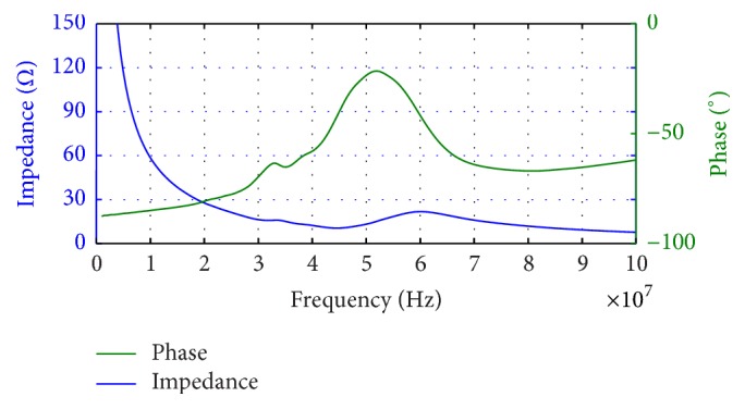
The measured impedance/phase of fabricated 1-3 piezocomposite.
Its electromechanical coupling coefficient Kt can be calculated as [15]
| (2) |
where fp is the parallel resonant frequency at which the resistance reaches the maximum and fs is the resonant frequency at which the conductance reaches the minimum. For our sample, fs is 44.05 MHz and fp is 60.36 MHz, so according to (2), Kt is about 0.70, which was higher than pure bulk ceramic (~0.5).
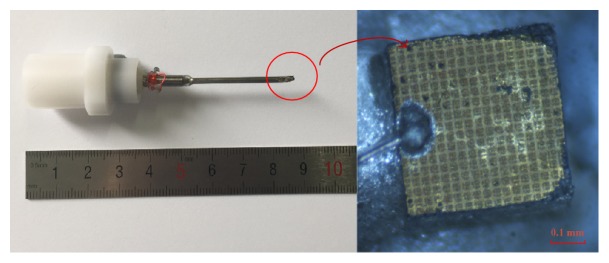
In the shaping process, the composite was firstly heated at 60°C for 1 hour to make it more flexible and then quickly mounted on a 3 mm radius PTFE ball with wax. The PTFE ball was used as the curving jig, which decides the focal length of the transducer. Conductive silver epoxy E-Solder 3022 was applied to the composite as the backing material in a PDMS (polydimethylsiloxane) mold. After curing at room temperature, the sample was heated to remove the PTFE ball. Then the sample was diced into the size of 0.6 mm × 0.6 mm. The individual piece was placed in a 1.2 mm diameter needle housing; the center core and mesh wire of a coaxial wire were connected to the piezocomposite surface and backing layer, respectively, with silver conductive. The gap between the transducer and the stainless steel needle was filled in by an insulating epoxy. At last, a 9 μm Parylene C layer was coated as its matching layer. The final fabricated focusing transducer was shown in Figure 2.
Figure 2.
The fabricated focusing IVUS transducer.
3. Results and Discussion
A DPR500 (pulse amplitude: 90 V, gain: 0 dB, filter: 5~300 MHz, RPF: 200 Hz, JSR Ultrasonics, USA) was used as the pulser-receiver to measure the center frequency, −6 dB bandwidth, and pulse echo amplitude of the fabricated focusing transducer and flat transducer. The pulse echo response was measured by recording the reflection from a quart polyethylene plastics flat placed at 3 mm in front of the transducer. The measured center frequency is 51.78 MHz, the −6 dB bandwidth is 107.21%, and the pulse half width is 17.37 ns just as Figure 3(a) shows. And the transducer pulse echo amplitude was measured as 404 mV with 50 Ω coupling impedance setting. For comparison, a flat IVUS transducer (unfocused) with the same diameter 0.6 mm was fabricated. This flat transducer was composed of the same 1-3 piezocomposite material, a Parylene C matching layer, and E-Solder 3022 backing layer. According to its pulse echo waveform and corresponding frequency spectrum as shown in Figure 3(b), its measured center frequency, −6 dB bandwidth, pulse half width, and amplitude were 53.77 MHz, 64.77%, 29.86 ns, and 156 mV, respectively.
Figure 3.
Pulse echo response and spectrum of (a) fabricated focusing IVUS transducer and (b) fabricated flat IVUS transducer.
The acoustic distribution was measured by a 3D scanning system UMS III (scan step resolution 0.001 mm, Precision Acoustics Ltd., Dorchester, UK) with a specially calibrated HGL-0085 hydrophone (20~60 MHz), as shown in Figure 4.
Figure 4.
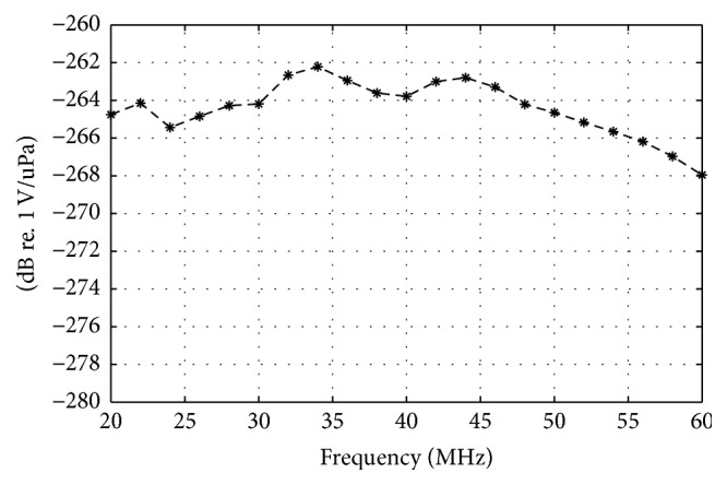
The response of HGL-0085 hydrophone with special calibration in the range of 20~60 MHz. Measurement uncertainty: 20~40 MHz, 2.2 dB; 40~60 MHz, 3.0 dB.
The hydrophone measurement step size was 30 μm. The acoustic intensity distribution of this fabricated transducer along z-axis was measured as shown in Figure 5. For avoiding the collision between the tested hydrophone and transducer, the recorded data was beginning at 0.5 mm away from the transducer. The measured focal length along the axial direction is 2.98 mm, which is very close to the designed focal length 3 mm. While the intensity of a flat IVUS transducer oscillates sharply in the near field range, then because of the attenuation, it will decrease linearly with the distance.
Figure 5.

The acoustic intensity distribution of fabricated focusing IVUS transducer along z-axis.
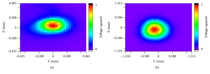
Because the lateral resolution is determined by the beam width perpendicular to the direction of wave propagation in an imaging plane, the transducer's acoustic intensity distributions in the focal plane (X-Y plane) were scanned with UMS III. According to the focal plane result in Figure 6(a), the diameter of the focal point of the fabricated focusing IVUS transducer (at −6 dB) is about 100 μm, which is one-third of the flat IVUS transducer's 300 μm, just as Figure 6(b) shows. These results indicate that the focusing IVUS transducer can achieve a higher lateral imaging resolution than usual flat ones.
Figure 6.
Measured acoustic intensity distribution of (a) fabricated focusing IVUS transducer; (b) fabricated flat IVUS transducer in the natural focus plane (X-Y plane).
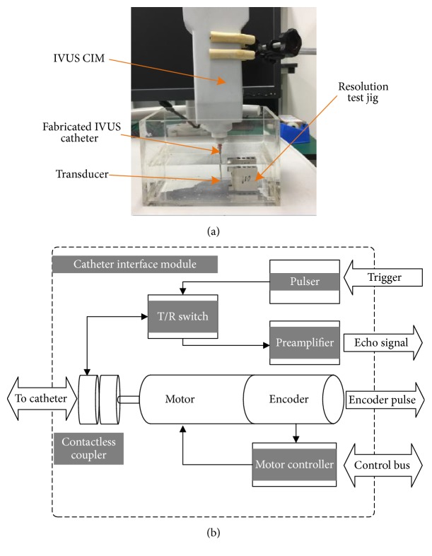
The imaging resolution was tested by our IVUS system [16]. The transducer was fixed on the top of a catheter, and the catheter is driven by a motor, which is in the IVUS catheter interface module (CIM), to do a rotary scan. The block diagram of CIM is shown in Figure 7(b). A single-element rotary scanning catheter is utilized to fix and rotate the transducer, which can spin at a speed of 1800 RPM. In the CIM, a contactless coupler with a flatten transfer curve from 10 to 110 MHz with an attenuation better than −1 dB is designed and manufactured to transfer high frequency signals between rotary and stationary side. For each cycle the catheter have turned, a frame composed of 512 scan lines would be captured. 12 bits analog to digital converter rate with a sampling rate of 220 MSPS ensure the echo information in enough frequency range could be recorded and provide a 25 fps imaging speed. More details of our IVUS system can be found in our published [16].
Figure 7.
The imaging resolution test system: (a) experimental setup and (b) the block diagram of IVUS CIM (catheter interface module) [16].
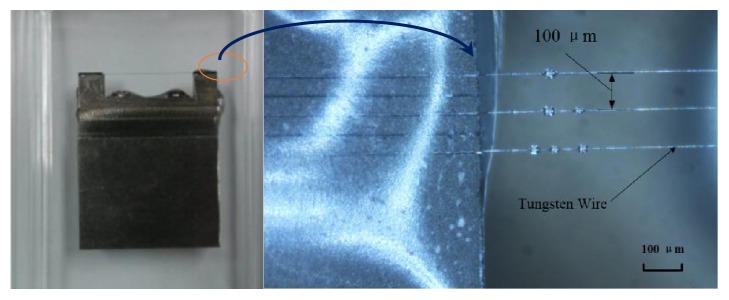
The imaging targets were some resolution test jigs with fixed interval tungsten wires, including 50 μm, 60 μm, 70 μm, 80 μm, 90 μm, 100 μm, 200 μm, 300 μm, and 400 μm, just as Figure 8 shows. The diameter of tungsten wires is 10 μm. When testing the axial resolution, the transducer was adjusted to be perpendicular to the wire phantom, while for lateral resolution testing it will be parallel to the wire phantom, just as Figure 7(a) shows. For getting the best lateral resolution, the distance between the phantom wires and transducer was set to be 3 mm just as the focal length.
Figure 8.
The imaging resolution test jig and tungsten wire phantom (100 μm).
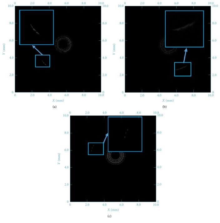
Figure 9 showed the lateral resolution testing results of the fabricated focusing and flat IVUS transducer, respectively. The bright arcs in the images represent the tungsten wires, while the center black hole and rings are caused by the transducer rotating. When using the 100 μm interval tungsten wire phantom, the image of three tungsten wires is only a blurred curve in Figure 9(b) detected by the flat transducer. It is impossible to distinguish each line in this image. Until the 300 μm interval tungsten wire phantom was used, the lines can be clearly separated in detected image in Figure 9(c). Therefore, the lateral resolution of flat IVUS transducer is tested as 300 μm.
Figure 9.
The lateral imaging resolution test images of (a) 100 μm interval tungsten wire phantoms with focusing IVUS transducer; (b) 100 μm interval tungsten wire phantoms with flat IVUS transducer; (c) 300 μm interval tungsten wire phantoms with flat IVUS transducer.
In the same way, the lateral resolution of fabricated focusing IVUS transducer is tested as 100 μm, just as Figure 9(a) showed, which is three times of the flat IVUS transducer. That is because the lateral beam width is greatly reduced by adjusting the focal performance of focused transducer [19]. Therefore, it is beneficial to try focused transducer to get high lateral resolution IVUS image.
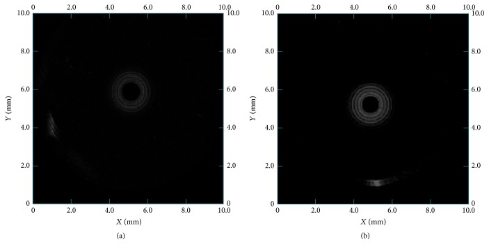
Similarly, Figures 10(a) and 10(b) showed the axial resolution testing images of the focusing and flat IVUS transducer, respectively. According to the results, the axial resolution of focusing IVUS transducer is 80 μm, and the flat IVUS transducer is 80 μm too. That is because the axial imaging resolution is mainly decided by center frequency of the transducer.
Figure 10.
The axial resolution test images of 80 μm interval tungsten wire phantoms with (a) focusing IVUS transducer and (b) flat IVUS transducer.
Furthermore, a hexagon hole phantom with 3 mm side length was used to test the imaging performance. The phantom was made by mixing 9 μm silicon carbide (2% by weight) and 3 μm aluminum oxide (2% by weight) with PDMS. When testing, the hexagon hole was filled with degas water, and the catheter distal with transducer was immersed into the hole. Figure 11 shows the phantom images detected by the fabricated focusing and flat IVUS transducer, respectively. Two images were both displayed in 12 dB dynamic range. Because of the high resolution and sensitivity, it is obvious that the image obtained by the focusing IVUS transducer was more clear and in a better shape. Particularly, the average contrast with respect to the locations of boundary and background in the images obtained by focusing and flat IVUS transducer were −13.1 dB and −16.2 dB, respectively.
Figure 11.
The image of hexagon phantom detected by (a) focusing IVUS transducer and (b) flat IVUS transducer.
At last, the main testing results were summarized in Table 2.
Table 2.
The comparison of measured focusing and flat IVUS transducer performance.
| Properties | Flat IVUS transducer |
Focusing IVUS transducer |
|---|---|---|
| Center frequency | 53.77 MHz | 51.78 MHz |
| Aperture | 0.6 mm | 0.6 mm |
| Bandwidth | 64.77% | 107.21% |
| Echo peak | 156 mV | 404 mV |
| Axial resolution | 80 μm | 80 μm |
| Lateral resolution | 300 μm | 100 μm |
4. Conclusion
In this study, a micro high frequency IVUS transducer with spherical focusing was successfully produced using PZT/epoxy 1-3 composite. The prototyped focusing IVUS transducer has a small size (0.6 × 0.6 mm), short focal length (3 mm), and high lateral imaging resolution (100 μm). The image obtained by our homemade IVUS system with the fabricated focusing transducer had a high signal to noise ratio and image quality. Based on these results, this micro high frequency focusing transducer has the potential for intravascular ultrasound imaging and various high frequency endoscopic ultrasound imaging.
Acknowledgments
This work is supported by the National Key Technology Research and Development Program of the Ministry of Science and Technology of China (Grant nos. 2016YFC0103302 and 2017YFC0107202), International Cooperation Program of Jiangsu Province (Grant nos. BZ2016023 and BK20161235), the Funds for Technology of Suzhou, China (Grant nos. SYG201433, 201456, and SZS201510), and China Postdoctoral Program (Grant no. 2015M581409).
Contributor Information
Xiaohua Jian, Email: simplejane1982@gmail.com.
Yaoyao Cui, Email: cuiyy@sibet.ac.cn.
Conflicts of Interest
The authors declare that there are no conflicts of interest regarding the publication of this paper.
References
- 1.Potkin B. N., Bartorelli A. L., Gessert J. M., et al. Coronary artery imaging with intravascular high-frequency ultrasound. Circulation. 1990;81(5):1575–1585. doi: 10.1161/01.CIR.81.5.1575. [DOI] [PubMed] [Google Scholar]
- 2.Schoenhagen P., DeFranco A., Nissen S., Tuzcu E. IVUS Made Easy. CRC Press; 2005. [DOI] [Google Scholar]
- 3.Prati F., Regar E., Mintz G. S., et al. Expert review document on methodology, terminology, and clinical applications of optical coherence tomography: physical principles, methodology of image acquisition, and clinical application for assessment of coronary arteries and atherosclerosis. European Heart Journal. 2010;31(4):401–415. doi: 10.1093/eurheartj/ehp433. [DOI] [PubMed] [Google Scholar]
- 4.Foster F. S., Ryan L. K., Lockwood G. R. Intravascular Ultrasound. Springer Netherlands; 1993. High Frequency Ultrasound Scanning of the Arterial Wall; pp. 91–108. (Developments in Cardiovascular Medicine). [DOI] [Google Scholar]
- 5.Suri J. S., Wilson D. L., Laxminarayan S. Handbook of Biomedical Image Analysis. Boston, Ma, USA: Springer US; 2005. [DOI] [Google Scholar]
- 6.Rhee S. High frequency (IVUS) ultrasound transducer technology - Applications and challenges. Proceedings of the 2007 16th IEEE International Symposium on the Applications of Ferroelectrics, ISAF; May 2007; jpn. pp. 856–857. [DOI] [Google Scholar]
- 7.Andresen H., Nikolov S. I., Jensen J. A. Synthetic aperture focusing for a single-element transducer undergoing helical motion. IEEE Transactions on Ultrasonics, Ferroelectrics, and Frequency Control. 2011;58(5):935–943. doi: 10.1109/TUFFC.2011.1894. [DOI] [PubMed] [Google Scholar]
- 8.Huang D., Kim E. S. Micromachined acoustic-wave liquid ejector. Journal of Microelectromechanical Systems. 2001;10(3):442–449. doi: 10.1109/84.946804. [DOI] [Google Scholar]
- 9.Chen Y., Lam K. H., Zhou D., et al. High frequency PMN-PT single crystal focusing transducer fabricated by a mechanical dimpling technique. Ultrasonics. 2013;53(2):345–349. doi: 10.1016/j.ultras.2012.06.017. [DOI] [PubMed] [Google Scholar]
- 10.Lee J., Jang J., Chang J. H. Oblong-Shaped-Focused Transducers for Intravascular Ultrasound Imaging. IEEE Transactions on Biomedical Engineering. 2017;64(3):671–680. doi: 10.1109/TBME.2016.2572182. [DOI] [PubMed] [Google Scholar]
- 11.Yoon S., Williams J., Kang B. J., et al. Angled-focused 45 MHz PMN-PT single element transducer for intravascular ultrasound imaging. Sensors and Actuators, A: Physical. 2015;228:16–22. doi: 10.1016/j.sna.2015.02.037. [DOI] [PMC free article] [PubMed] [Google Scholar]
- 12.Li X., Ma T., Tian J., Han P., Zhou Q., Shung K. K. Micromachined PIN-PMN-PT crystal composite transducer for high-frequency intravascular ultrasound (IVUS) imaging. IEEE Transactions on Ultrasonics, Ferroelectrics, and Frequency Control. 2014;61(7):1171–1178. doi: 10.1109/TUFFC.2014.3016. [DOI] [PMC free article] [PubMed] [Google Scholar]
- 13.Yuan J. R., Jiang X., Cao P.-J., et al. High frequency piezo composites microfabricated ultrasound transducers for intravascular imaging. Proceedings of the 2006 IEEE International Ultrasonics Symposium, IUS; October 2006; can. pp. 264–268. [DOI] [Google Scholar]
- 14.Yuan J., Cao P., Romley R. Piezocomposite transducers. 2006, Google Patents.
- 15.Safari A., Akdoğan E. K. Piezoelectric and acoustic materials for transducer applications. Piezoelectric and Acoustic Materials for Transducer Applications. 2008:1–481. doi: 10.1007/978-0-387-76540-2. [DOI] [Google Scholar]
- 16.Xiang Y., Xu J., Lv T., Gu T., Han Z., Cui Y. A graphic processing unit based intravascular ultrasound (IVUS). Proceedings of the IEEE International Ultrasonics Symposium, IUS 2015; October 2015; twn. [DOI] [Google Scholar]
- 17.Brown J. A., Foster F. S., Needles A., Cherin E., Lockwood G. R. Fabrication and performance of a 40-MHz linear array based on a 1-3 composite with geometric elevation focusing. IEEE Transactions on Ultrasonics, Ferroelectrics, and Frequency Control. 2007;54(9):1888–1894. doi: 10.1109/TUFFC.2007.473. [DOI] [PubMed] [Google Scholar]
- 18.Jiang X., Yuan J. R., Cheng A., et al. Microfabrication of piezoelectric composite ultrasound transducers (PC-MUT); pp. 918–921. [DOI] [Google Scholar]
- 19.Saijo Y., Van der Steen A. F. W. Vascular ultrasound. Springer Science and Business Media; 2003. [Google Scholar]


