Abstract
Cable-type stretchable electrochemical pseudocapacitors based on multi-walled carbon nanotube (MWCNT) sheets and two different metal oxide nanopowders (NP), i.e., MnO2 and RuO2 are developed using a newly-devised dry painting method to mechanically fix the NP to the elastic rubber-based MWCNT electrode substrate, resulting in a porous buckling structured pseudocapacitor yarn. Highly stretchable stylene-ethylene/butylene-stylene (SEBS) is used as the supporting elastomeric core for wrapping with the MWCNT sheets and the electroactive NP. The dry painting can successfully deposit NP on the soft SEBS surface, which is normally an unfavorable substrate for coating alien materials. The resulting yarn-type pseudocapacitor, composed of eight-layered MWCNT sheets, three-layered RuO2, and two-layered MnO2, showing a diameter of approximately 400 μm with a porous buckling structure, records a specific capacitance of 25 F g−1. After being stretched by 200% in strain with no sacrifice of the porous buckling structure, the cable-type stretchable electrochemical pseudocapacitor yarn retains its electrical capacity, and is potentially applicable to energy storage devices for wearable electronics.
Introduction
Electrochemical capacitors are of great interest to a variety of industrial fields that demand high power density, such as devices that range from small electronic hand-held tools to relatively large electric vehicles, including rails and trams. They all commonly require ultrahigh electrochemical energy storage devices, and the field is even expanding to personal energy-carrying equipment in the form of wearable electronics1. Indeed, stretchable and wearable fabrics are about to be realized by the development of stretchable yarn- and sheet-type supercapacitors, which are also applicable to military purposes2–9. Such high energy storage devices are frequently combined with secondary batteries10,11, energy harvesting devices including photoelectrochemical cells, and finally, integrated power packs12,13.
Energetically, pseudocapacitors have more potential when charging a device with high energy storage capacity, due to the electrochemical capacitor-specific double-layer structure, and additional faradaic contribution from redox active materials. They are mostly prepared from transition metal oxides, metal sulfides, and in many cases, carbonaceous metal hybrid compounds14–21. In addition to the excellent cyclability, these materials have multiple redox potentials, enabling more rectangular-shaped current-voltage characteristics. As a result, high specific capacity with sufficient robustness can be obtained. However, the physically strong and age-resistive inorganic transition metals are expensive and inherently rigid, which makes them incompatible with stretchable devices in spite of the fact that some flexible devices based on nanowired materials have been introduced22–24. As an alternative, organic polymeric conductor-based pseudocapacitors are relatively inexpensive. The conducting polymer layers are easy to prepare via anodical electropolymerization, or spin coating followed by heat or UV curing25. Best of all, such conducting polymers are basically excellent bendable and stretchable materials. A common problem is that the organic material-based electrochemical capacitors suffer from limited cycling stability, and unwanted leakage current that mainly depends on the equivalent series resistance. Upon repeated charging and discharging processes, mechanically weak conducting polymers employed for a yarn-type pseudocapacitor can be more susceptible to time-dependent aging26. Supercapacitor yarns sandwiched in between two stretchable plastic substrates for better stability and stretchability have been reported27,28.
In this work, we introduce a newly devised highly versatile dry painting method to prepare metal oxide-based stretchable pseudocapacitors that have a porous buckling structure. As compared with the conventional electrochemical plating for metal oxide deposition, which usually produces a fragile metallic thin film in a liquid electrolyte phase, the dry painting method employs metal oxide nanopowders (NP) such as RuO2 and MnO2, and physically deposits the NP on a multi-walled carbon nanotube (MWCNT)-layered stretchable stylene-ethylene/butylene-stylene (SEBS) substrate in atmospheric condition. The physicochemical properties of the highly stretchable SEBS have been discussed elsewhere29. The RuO2 and MnO2 layers are dry painted on the substrate by turn, and the densified MWCNT sheet layer between them effectively holds the NP tightly on the substrate. The resulting stretchable pseudocapacitor yarns are characterized by cyclic voltammetry (CV), electrochemical impedance spectroscopy (EIS), chronopotentiometry (CP), and scanning electron microscopy (SEM).
Results
Morphology of stretchable organic-inorganic hybrid pseudocapacitor yarn
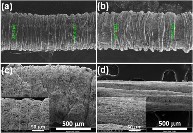
Buckling structure, known as a topological pattern that can effectively minimize the spatial constraint of a stretchable device, and one of the most important demands of wearable electronics, is retained after extension of the pseudocapacitor yarn by about 200%. Figure 1a and b show SEM images obtained before and after extending the pseudocapacitor yarn a thousand times. The number of wrinkles per unit length and the diameter of the pseudocapacitor yarn are not appreciably changed after the repeated severe extensions, which verifies the excellent physical reproducibility and ruggedness of the buckling structure. The wavelength of each wrinkle is about 50 μm. Comparison of the SEM image of Fig. 1c with that of Fig. 1d confirms that the stretched surface of the pseudocapacitor is indeed crack free.
Figure 1.
SEM images of stretchable pseudocapacitors: (a) as-prepared pseudocapacitor; (b) pseudocapacitor after a thousand times of repeated stretching by 200%; (c) magnified image of the as-prepared pseudocapacitor showing a wavelength of about 50 μm; (d) magnified image of the stretched pseudocapacitor during extension.
Capacitive characteristics of bare MWCNT-based capacitors
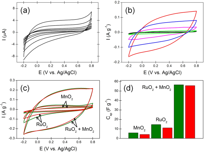
The bare MWCNT sheets used in this work basically function as a wrapping material to tightly fix electroactive materials on the SEBS elastomer, and simultaneously act as an electrical conductor that can also partly contribute to the total capacitance. It is known that the many defects naturally formed on carbonaceous materials during various preparation procedures in the form of chemical functional groups can contribute to faradaic capacitance30. If the faradaic contribution from the MWCNT sheets was big enough, and even compatible with that from the electroactive NP, it would be meaningful to differentiate the two contributions from each other. It has also been reported that a wire-shaped supercapacitor based on a MWCNT fiber may be possible2. To quantitatively determine the contribution from bare MWCNT sheets to the total capacitance, a separately-prepared capacitor yarn was prepared that was composed of SEBS elastomer and 12-layered MWCNT sheets that were absolutely free from any electroactive material. Fig. 2a shows the cyclovoltammetrically recorded capacitive behavior. The measured specific capacitance was 0.133 F g−1, which was less than 1% portion of the total capacitance of the hybrid pseudocapacitor yarn. Accordingly, it is concluded that the MWCNT-sheet layers having a complex reticulate structure in the hybrid pseudocapacitor yarn exclusively acts by grabbing electroactive RuO2 and MnO2 NP while showing negligible capacitance contribution, and also provides a low resistive current path. In this work, mass-based dimension is preferred for the electrical capacity of the pseudocapacitor yarn, rather than the other dimensions such as length-based and area-based ones, because these alternative dimensions strongly depend on how much the pseudocapacitor yarn is stretched. The diameter of SEBS elastomer decreases with extending the elastomer (Supplementary Fig. S1). This means that precise determinations of the cross-sectional area of the SEBS and of the electroactive multilayers that directly cover the SEBS core are in practical terms unavailable.
Figure 2.
(a) Cyclic voltammograms of the yarn type electrochemical capacitor composed of SEBS elastomer and 12-layered MWCNT sheets wrapping the SEBS elastomer at scan rates of 5, 10, 20, 50, and 100 mV s−1 in a 1 M Na2SO4 solution. (b) Cyclic voltammograms of variously prepared yarn type pseudocapacitors using different electroactive materials: 10-layered MnO2 (green); 10-layered RuO2 (pink); 3-layered RuO2 + 2-layered MnO2 (red). Electrolyte = 1 M Na2SO4, and scan rate = 5 mV s−1. Two additional capacitors, a Pt-free one based on 3-layered RuO2 and 2-layered MnO2 (blue), and a 12-layered MWCNT-based one with no electroactive materials (black), are also shown for comparison. (c) Cyclic voltammograms of variously prepared yarn type pseudocapacitors using different electroactive materials: electrolyte = 1 M Na2SO4; scan rate = 10 mV s−1. Note that green and red solid lines denote graphs obtained before and after stretching the pseudocapacitor yarn, respectively. (d) Bar graphs of each pseudocapacitors showing decrease in specific capacitance of the pseudocapacitors: green and red bars denote graphs obtained before and after stretching the pseudocapacitor yarn a thousand times, respectively. Note that 1 layer of Pt powder was employed for each pseudocapacitor to reduce the equivalent series resistance and different layer numbers for different yarns are employed to adjust their stretchability to be around 200%.
Specific capacitances of various hybrid pseudocapacitor yarns
RuO2 and MnO2 are widely used electroactive materials in electrochemical capacitors, due to their multi-redox potentials that enhance capacitive current flows, outstanding physicochemical stability, and theoretically high specific capacitances that are larger than one thousand farad per gram31,32. Although a variety of different methods for the deposition of these electroactive materials are available, physical deposition of the RuO2 or MnO2 NP denoted by the dry painting in this work was devised in order to avoid serious damage to the stretchability of SEBS elastomer during deposition of the NP on the elastomer. Conventional chemical vapor deposition (CVD) or electrochemical deposition that generally occur in an aqueous medium may provide evenly distributed high quality RuO2 or MnO2 thin films. However, the deposited thin films prepared by these methods are fragile, and easily cracked during consecutive extension and contraction of the stretchable capacitors. Figure 2b shows cyclic voltammograms of the various pseudocapacitor yarns using different electroactive materials, which indicate that mixing the two electroactive materials in the ratio of RuO2:MnO2 = 3:2 on the basis of the deposited layer numbers dramatically enhances the specific capacitance. The capacity would be even better if an additional layer of Pt powders aiming to decrease the equivalent series resistance was to be separately deposited. The electrocatalytic effect on oxygen reduction and evolution reactions enhanced by the use of RuO2 and MnO2 together in lithium-based secondary batteries and methanol fuel cells have been introduced33–35. A similar effect can be observed in an electrochemical capacitor having a similar structure to the batteries and fuel cells. From the crystallographic point of view, tunnel size and surface area seem to be the major factors affecting capacity of the MnO2-based supercapacitors, and α-MnO2, which shows wider tunnel size and larger surface area than the other types of MnO2, gives the best electrical capacity36. The poor electrical conductivity of MnO2 can be complemented by adding a small amount of highly-conductive RuO2, and this applies to an electrochemical double-layer capacitor (EDLC)37. Figure 2b verifies that in the stretchable pseudocapacitor, as well as in the traditional EDLC as proven previously, MnO2 and RuO2 complement each other. Cyclic voltammograms of the mixed-layered electrode at different scanning rates are presented in Supplementary Fig. S2 to clarify the rate performance. The specific capacitance of the stretchable pseudocapacitor yarn absolutely decreases by the repeated extensions probably because small portion of the fixed NP are lost during stretching and releasing the yarn. Figure 2c,d show the reduced specific capacitance with the extensions which is confirmed by the cyclic voltammetry of variously prepared yarn type pseudocapacitors. The bar graphs demonstrate that the specific capacitance reduces by approximately 29 ± 5% for the MnO2-based pseudocapacitor, 24 ± 5% for the RuO2-based pseudocapacitor, and 2 ± 0.5% for the MnO2 + RuO2-based pseudocapacitor after stretching the yarn a thousand times.
Electrochemical impedance spectra
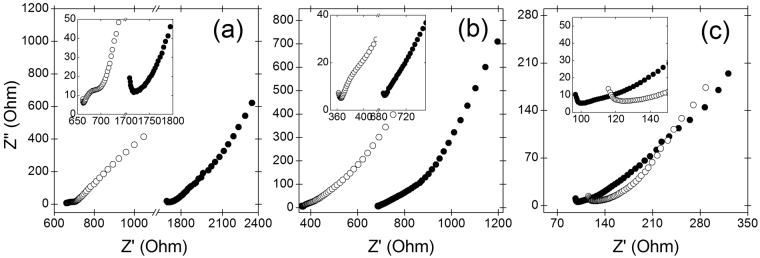
Electrochemical double layer capacitors using non-porous electrodes usually show a unique vertical line in the Nyquist plot, which is traditional for a capacitor element. The semicircle diameter of the Nyquist plot represents the sum of the internal resistance of electrode and some other factors such as the electrolyte resistance and contact resistance. Therefore, decreased circle diameter would mean a decrease of the electrode resistance if the other resistances were not variables38. However, in a porous electrode-based supercapacitor, such a semicircle is not clearly shown, and no vertical line but a sloped line depending on the pore structure will be observed30. Approximately, we can evaluate internal resistances of each porous pseudocapacitors with one another by comparing the real components of the observed impedances in a complex plane because equivalent series resistance is a function of the electrolyte resistance (mostly constant), electrode resistance, and the contact resistance39. Figure 3 shows the EIS spectra obtained from the yarn type stretchable pseudocapacitors clearly demonstrate diagonal lines with the typical slope of porous electrode substrates. Indeed, this Warburg like behavior is quite common with porous substrates30, and Supplementary Fig. S3 confirms that the stretchable pseudocapacitor yarns in this work have such a highly-porous buckling-structured electroactive layer. The porosity of the electroactive multilayers is around 80% (detailed calculation is available from supporting information). Randomly oriented MWCNT sheets before stretching alter into a well-aligned unidirectional microstructure after stretching. The alignment of electrically conductive MWCNTs along the stretching direction can cause serious decrease in electrical conductivity, especially in the radial direction. Figure 3a,b indicate that the internal series resistances of both MnO2-, and RuO2-based pseudocapacitors increase after stretching them from 660 Ω to 1710 Ω, and from 365 Ω to 690 Ω, respectively, showing an approximate two-fold increase in series resistance. Interestingly, internal series resistance change before and after stretching is not clearly evident when MnO2 and RuO2 layers are alternatively deposited on MWCNT sheet substrates, and used as electroactive materials for the pseudocapacitor yarn. More importantly, although the electrical conductivity of RuO2 is much larger than that of MnO2, the internal series resistances of the mixed-layered pseudocapacitor showing around 120 and 100 Ω before and after stretching (Fig. 3c) are even smaller than those of the RuO2-deposited pseudocapacitor.
Figure 3.
EIS spectra of (a) 10-layered MnO2-deposited electrode, (b) 10-layered RuO2-deposited electrode, and (c) mixed-layered pseudocapacitive electrode composed of 3-layered RuO2 and 2-layered MnO2. VDC = 0 V (vs. Ag/AgCl); amplitude = 10 mV; frequency varies from 100 kHz to 100 mHz; electrolyte = 1 M Na2SO4. Note that open and closed circles denote values obtained before and after stretching the pseudocapacitor yarn, respectively.
Charging and discharging characteristics
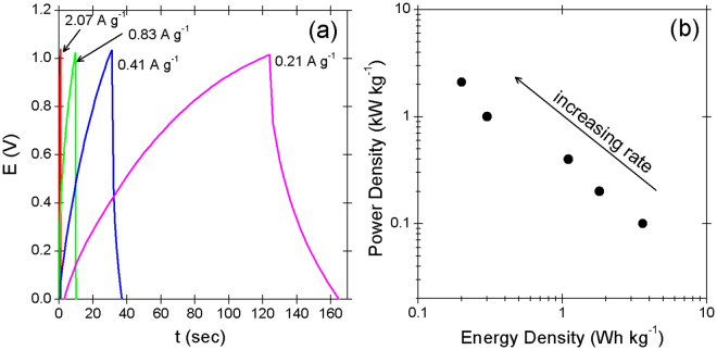
Figure 4a shows that non-linear constant current charge/discharge curves that feature a pseudo-type energy storage mechanism govern the stretchable pseudocapacitor yarn. The specific capacitance at a rate of 0.2 A g−1 is approximately 25 F g−1. Supporting information 3 provides more detailed descriptions of the computation. Figure 4b shows that the corresponding power density and energy density are inversely proportional to each other in the logarithmic plot.
Figure 4.
(a) Chronopotentiometric responses of the 3-layered RuO2 + 2-layered MnO2-based pseudocapacitive electrode in 1 M Na2SO4 solution at various charge rates: reference electrode = Ag/AgCl; counter electrode = Pt wire. (b) Ragone plots of the stretchable pseudocapacitor at various charge rates are also shown.
Discussion
A variety of different wire electrode-based energy harvesting and energy storage devices have been introduced in recent years, such as dye-sensitized solar cells, supercapacitors, and batteries10,40,41. Although some of them will likely be commercially available in the near future42, they still suffer from either poor flexibility or poor durability. Therefore, a combination of intrinsically robust inorganic materials with naturally flexible organic materials may give the best results. The problem lies in how to successfully combine them together, without sacrificing too much strength of either organic or inorganic material. In most cases, when both materials are mixed together, the strength of one of them will be totally lost, and unfortunately, the attempt to solve this problem from a macroscopic point of view cannot provide suitable answers. SEBS, as a highly stretchable organic material and an electrical insulator, can have the surface modulated to be electrically conductive by being combined with MWCNT sheets, without serious sacrifice of its stretchability. The MWCNT sheets provide the SEBS with high conductivity. Similarly, the SEBS provides the MWCNT sheets with excellent stretchability, by dispersing the local stress formed during the extension and contraction procedure all the way through the entire MWCNT sheets43. Additionally, dry painting of inorganic metal oxides NP on the organic SEBS/MWCNT substrate is a mild and gentle process based on physical adsorption, rather than more radical chemical adsorption, which occasionally results in lethal damage to the organic substrate by any covalent bond formation. Although neither the synergetic effect nor the optimized mixture composition including the optimized layer number of MnO2 and RuO2 NP in a yarn-type pseudocapacitor are yet fully understood, dry painting is highly versatile, and widely applicable to any NP or other nanostructured materials, especially for yarn-type porous buckling structures.
Methods
Preparation of materials
As a conductive substrate, MWCNT sheets were prepared by being withdrawn from the MWCNT forest that was previously grown on a p-type silicon wafer (4-inch-diameter and 17 Ω cm of resistivity) by conventional CVD44. A photo image that shows how to prepare the specified MWCNT sheet from the MWCNT forest is available (Supplementary Fig. S4). The general specifications of the MWCNT forest, including the electrical conductivity, specific surface area, tensile strength, and volumetric density, are available elsewhere45. Ruthenium Oxide (RuO2) and Manganese Oxide (MnO2) as electroactive materials purchased from Sigma-Aldrich were first finely ground to have a diameter less than 1 μm, and then deposited on the MWCNTs by the dry painting method. Gel electrolyte was prepared by dissolving a 30 wt% portion of H3PO4 (Sigma-aldrich) into a 70 wt% portion of polyvinyl alcohol (PVA, Sigma-Aldrich) at 70 °C for 4 hours.
Electrochemistry
CV diagrams and EIS spectra of yarn type pseudocapacitors in a three-electrode aqueous system composed of Ag/AgCl reference electrode and a Pt wire counter electrode were obtained using a Reference 600 (Gamry Instruments) and Ivium CompactStat 2, respectively. A 1 M Na2SO4 solution was used as a liquid electrolyte. All electrochemical reagents were used without further purification.
Fabrication of yarn type stretchable pseudocapacitors
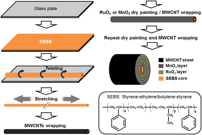
Figure 5 shows the fabrication procedure of a stretchable pseudocapacitor as follows: a super elastic SEBS core was used as a bottom substrate, and the detailed information about the preparation of SEBS is available29. The SEBS elastomer string is first pre-strained by 450%, and then the MWCNT sheet (10 × 1.1 cm) wraps the pre-strained SEBS elastomer using a laboratory made roller. RuO2 and MnO2 nano particles are alternatively deposited on each MWCNT layer having a unique reticulated structure, which enables any micro and nano particles to be easily captured, and firmly fixed on the cylindrical MWCNT surface layer. Highly stretchable but electrically nonconductive SEBS compensates for the much less stretchable but highly conductive MWCNT layers with each other. The dry painting of the MWCNT-wrapped surface with metallic NP should be sufficient to fully saturate the particle-catching sites of the MWCNT layer, which provides a beneficial effect on suppressing device-to-device variation. Finally, spraying methanol on the stretchable yarn densifies the MWCNT layers, allowing more tight binding of the NP, in order to avoid being liberated from the MWCNT surface. The structural configuration of the stretchable pseudocapacitor depicted in Fig. 5 features alternating metal oxide layers. Three sheets of MWCNT layers are pre-positioned deep inside, i.e., right above the SEBS core, to reduce the equivalent series resistance. After drying, the pseudocapacitor yarn composed of SEBS, MWCNT sheets, RuO2, and MnO2 NP is gently coated with the gel electrolyte, and the pre-strained yarn is eventually released to assume a buckling structure, which is an ordered periodic one dimensional wavy pattern, as apparently formed in the SEBS elastomer29. Two gel electrolyte-coated pseudocapacitor yarns are softly twisted with each other, and the gel electrolyte added again on the twisted yarns for better electrical contact. A video clip that shows the stretching and releasing of the pseudocapacitor yarn is available (Video S1). 200% of stretchability can be obtained with electroactive layers composed of RuO2 (3 layers) and MnO2 (2 layers).
Figure 5.
Fabrication process and schematic structure of stretchable pseudocapacitor. Note that the innermost layer from the SEBS core is 3-layered MWCNT sheets, while the other MWCNT layers are 1-layered MWCNT sheet including the outermost one. Note that molecular structure of SEBS is also shown for better understanding.
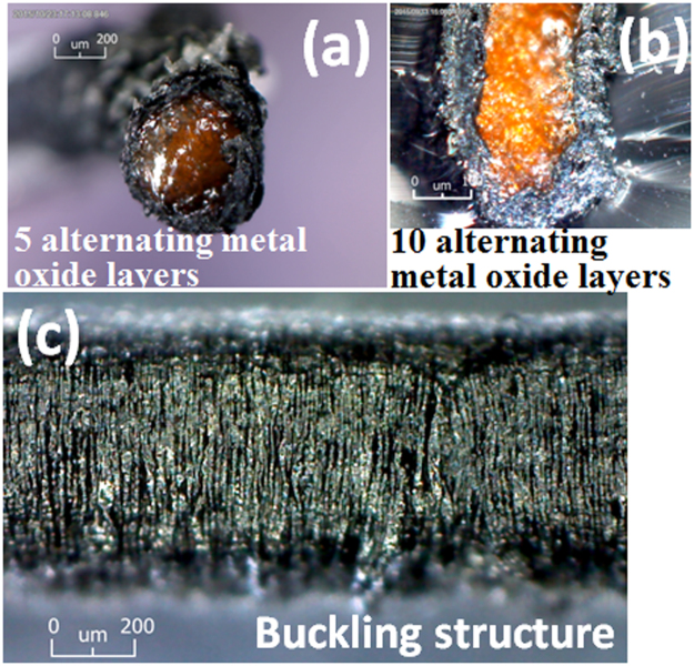
Figure 6a,b demonstrate a clear boundary line between the highly stretchable SEBS core and the surrounding electroactive composite layer that is responsible for the high pseudocapacitance. However, the electroactive layers composed of MWCNT sheets and NP layers, even though they are prepared by a layer-by-layer process, are indistinguishable from each other, indicating that the electroactive composite layers form an electrical single phase (Supplementary Fig. S5), and at least in the outer radial direction, present negligible contact resistance with the relaxed pseudocapacitor yarns (see Fig. 3 for more detailed information). Figure 6c also shows a perfect buckling structure featuring many vertical wrinkles of the stretchable pseudocapacitor yarn.
Figure 6.
Cross-sectional photo images of the stretchable pseudocapacitor composed of MWCNT sheets, RuO2, and MnO2 NP with (a) five, and (b) ten layers of NP, respectively. Note that RuO2 layer is the innermost layer for each. Image (c) shows the buckling structure of the stretchable pseudocapacitor yarn.
Electronic supplementary material
Acknowledgements
This work was supported by the National Research Foundation (Grant No. 2016R1C1B2012340) of the Ministry of Science, ICT & Future Planning (MSIP). Author 1 and Author 2 contributed equally to this work.
Author Contributions
D.W.L. and J.H.J. conceived the idea and designed the experiments; J.H.L. and D.W.L. contributed fabrication of materials, mechanical and electrochemical characterizations; J.H.J. and N.K.M. analyzed data; J.H.J. and N.K.M. wrote the paper.
Competing Interests
The authors declare that they have no competing interests.
Footnotes
Electronic supplementary material
Supplementary information accompanies this paper at 10.1038/s41598-017-12375-7.
Publisher's note: Springer Nature remains neutral with regard to jurisdictional claims in published maps and institutional affiliations.
Contributor Information
Nam Ki Min, Email: nkmin@korea.ac.kr.
Joon-Hyung Jin, Email: jjh1023@kgu.ac.kr.
References
- 1.Liu LB, Yu Y, Yan C, Li K, Zheng ZJ. Wearable energy-dense and power-dense supercapacitor yarns enabled by scalable graphene-metallic textile composite electrodes. Nat Commun. 2015;6:7260. doi: 10.1038/ncomms8260. [DOI] [PMC free article] [PubMed] [Google Scholar]
- 2.Xu P, et al. Carbon Nanotube Fiber Based Stretchable Wire-Shaped Supercapacitors. Adv Energy Mater. 2014;4:1300759. doi: 10.1002/aenm.201300759. [DOI] [Google Scholar]
- 3.Zhao C, Shu KW, Wang CY, Gambhir S, Wallace GG. Reduced graphene oxide and polypyrrole/reduced graphene oxide composite coated stretchable fabric electrodes for supercapacitor application. Electrochim Acta. 2015;172:12–19. doi: 10.1016/j.electacta.2015.05.019. [DOI] [Google Scholar]
- 4.Zhang ZT, et al. Superelastic Supercapacitors with High Performances during Stretching. Adv Mater. 2015;27:356–362. doi: 10.1002/adma.201404573. [DOI] [PubMed] [Google Scholar]
- 5.Xie BH, et al. Shape-Tailorable Graphene-Based Ultra-High-Rate Supercapacitor for Wearable Electronics. Acs Nano. 2015;9:5636–5645. doi: 10.1021/acsnano.5b00899. [DOI] [PubMed] [Google Scholar]
- 6.Li FW, Chen JT, Wang XS, Xue MQ, Chen GF. Stretchable Supercapacitor with Adjustable Volumetric Capacitance Based on 3D Interdigital Electrodes. Adv Funct Mater. 2015;25:4601–4606. doi: 10.1002/adfm.201500718. [DOI] [Google Scholar]
- 7.Huang Y, et al. Magnetic-Assisted, Self-Healable, Yarn-Based Supercapacitor. Acs Nano. 2015;9:6242–6251. doi: 10.1021/acsnano.5b01602. [DOI] [PubMed] [Google Scholar]
- 8.Chen T, Hao R, Peng HS, Dai LM. High-Performance, Stretchable, Wire-Shaped Supercapacitors. Angew Chem Int Edit. 2015;54:618–622. doi: 10.1002/anie.201409385. [DOI] [PubMed] [Google Scholar]
- 9.Lyu XM, Su FH, Miao MH. Two-ply yarn supercapacitor based on carbon nanotube/stainless steel core-sheath yarn electrodes and ionic liquid electrolyte. J Power Sources. 2016;307:489–495. doi: 10.1016/j.jpowsour.2015.12.114. [DOI] [Google Scholar]
- 10.Ren J, et al. Twisting Carbon Nanotube Fibers for Both Wire-Shaped Micro-Supercapacitor and Micro-Battery. Adv Mater. 2013;25:1155–1159. doi: 10.1002/adma.201203445. [DOI] [PubMed] [Google Scholar]
- 11.Zhang F, et al. A high-performance supercapacitor-battery hybrid energy storage device based on graphene-enhanced electrode materials with ultrahigh energy density (vol 6, pg 1623, 2013) Energ Environ Sci. 2014;7:3086–3086. doi: 10.1039/C4EE90033B. [DOI] [Google Scholar]
- 12.Reddy BN, Kumar PN, Deepa M. A Poly(3,4-ethylenedioxypyrrole)-Au@WO3-Based Electrochromic Pseudocapacitor. Chemphyschem. 2015;16:377–389. doi: 10.1002/cphc.201402625. [DOI] [PubMed] [Google Scholar]
- 13.Ramadoss A, et al. Piezoelectric-Driven Self-Charging Supercapacitor Power Cell. Acs Nano. 2015;9:4337–4345. doi: 10.1021/acsnano.5b00759. [DOI] [PubMed] [Google Scholar]
- 14.Yun TG, Hwang BI, Kim D, Hyun S, Han SM. Polypyrrole-MnO2-Coated Textile-Based Flexible-Stretchable Supercapacitor with High Electrochemical and Mechanical Reliability. Acs Appl Mater Inter. 2015;7:9228–9234. doi: 10.1021/acsami.5b01745. [DOI] [PubMed] [Google Scholar]
- 15.Muller GA, Cook JB, Kim HS, Tolbert SH, Dunn B. High Performance Pseudocapacitor Based on 2D Layered Metal Chalcogenide Nanocrystals. Nano Lett. 2015;15:1911–1917. doi: 10.1021/nl504764m. [DOI] [PubMed] [Google Scholar]
- 16.Liao QY, Li N, Jin SX, Yang GW, Wang CX. All-Solid-State Symmetric Supercapacitor Based on Co3O4 Nanoparticles on Vertically Aligned Graphene. Acs Nano. 2015;9:5310–5317. doi: 10.1021/acsnano.5b00821. [DOI] [PubMed] [Google Scholar]
- 17.Hu ZM, et al. Al-doped alpha-MnO2 for high mass-loading pseudocapacitor with excellent cycling stability. Nano Energy. 2015;11:226–234. doi: 10.1016/j.nanoen.2014.10.015. [DOI] [Google Scholar]
- 18.Guan C, et al. Iron Oxide-Decorated Carbon for Supercapacitor Anodes with Ultrahigh Energy Density and Outstanding Cycling Stability. Acs Nano. 2015;9:5198–5207. doi: 10.1021/acsnano.5b00582. [DOI] [PubMed] [Google Scholar]
- 19.Feng C, et al. Sub-3 nm Co3O4 Nanofilms with Enhanced Supercapacitor Properties. Acs Nano. 2015;9:1730–1739. doi: 10.1021/nn506548d. [DOI] [PubMed] [Google Scholar]
- 20.Cai XY, et al. High-performance asymmetric pseudocapacitor cell based on cobalt hydroxide/graphene and polypyrrole/graphene electrodes. J Power Sources. 2015;275:298–304. doi: 10.1016/j.jpowsour.2014.10.204. [DOI] [Google Scholar]
- 21.Acerce M, Voiry D, Chhowalla M. Metallic 1T phase MoS2 nanosheets as supercapacitor electrode materials. Nat Nanotechnol. 2015;10:313–318. doi: 10.1038/nnano.2015.40. [DOI] [PubMed] [Google Scholar]
- 22.Yan J, et al. Carbon nanotube/MnO2 composites synthesized by microwave-assisted method for supercapacitors with high power and energy densities. J Power Sources. 2009;194:1202–1207. doi: 10.1016/j.jpowsour.2009.06.006. [DOI] [Google Scholar]
- 23.Chen PC, Shen GZ, Shi Y, Chen HT, Zhou CW. Preparation and Characterization of Flexible Asymmetric Supercapacitors Based on Transition-Metal-Oxide Nanowire/Single-Walled Carbon Nanotube Hybrid Thin-Film Electrodes. Acs Nano. 2010;4:4403–4411. doi: 10.1021/nn100856y. [DOI] [PubMed] [Google Scholar]
- 24.Chen PC, Chen HT, Qiu J, Zhou CW. Inkjet Printing of Single-Walled Carbon Nanotube/RuO2 Nanowire Supercapacitors on Cloth Fabrics and Flexible Substrates. Nano Res. 2010;3:594–603. doi: 10.1007/s12274-010-0020-x. [DOI] [Google Scholar]
- 25.Anothumakkool B, Soni R, Bhange SN, Kurungot S. Novel scalable synthesis of highly conducting and robust PEDOT paper for a high performance flexible solid supercapacitor. Energ Environ Sci. 2015;8:1339–1347. doi: 10.1039/C5EE00142K. [DOI] [Google Scholar]
- 26.Choi C, et al. Stretchable, Weavable Coiled Carbon Nanotube/MnO2/Polymer Fiber Solid-State Supercapacitors. Sci Rep-Uk. 2015;5:9387. doi: 10.1038/srep09387. [DOI] [PMC free article] [PubMed] [Google Scholar]
- 27.Zhang N, et al. Biaxially stretchable supercapacitors based on the buckled hybrid fiber electrode array. Nanoscale. 2015;7:12492–12497. doi: 10.1039/C5NR03027G. [DOI] [PubMed] [Google Scholar]
- 28.Niu ZQ, et al. Highly Stretchable, Integrated Supercapacitors Based on Single-Walled Carbon Nanotube Films with Continuous Reticulate Architecture. Adv Mater. 2013;25:1058–1064. doi: 10.1002/adma.201204003. [DOI] [PubMed] [Google Scholar]
- 29.Liu ZF, et al. Hierarchically buckled sheath-core fibers for superelastic electronics, sensors, and muscles. Science. 2015;349:400–404. doi: 10.1126/science.aaa7952. [DOI] [PubMed] [Google Scholar]
- 30.Conway, B. E. Electrochemical supercapacitors: scientific fundamentals and technological applications. (Plenum Press, 1999).
- 31.Chen LY, et al. Toward the Theoretical Capacitance of RuO2 Reinforced by Highly Conductive Nanoporous Gold. Adv Energy Mater. 2013;3:851–856. doi: 10.1002/aenm.201300024. [DOI] [Google Scholar]
- 32.Huang M, Li F, Dong F, Zhang YX, Zhang LL. MnO2-based nanostructures for high-performance supercapacitors. J Mater Chem A. 2015;3:21380–21423. doi: 10.1039/C5TA05523G. [DOI] [Google Scholar]
- 33.Wang GQ, et al. Nanostructured porous RuO2/MnO2 as a highly efficient catalyst for high-rate Li-O-2 batteries. Nanoscale. 2015;7:20614–20624. doi: 10.1039/C5NR07486J. [DOI] [PubMed] [Google Scholar]
- 34.Jang H, et al. Sea Urchin Shaped alpha-MnO2/RuO2 Mixed Oxides Nanostructure as Promising Electrocatalyst for Lithium-Oxygen Battery. J Electrochem Soc. 2015;162:A300–A307. doi: 10.1149/2.0231503jes. [DOI] [Google Scholar]
- 35.Zhou C, et al. Facile Preparation of an Excellent Pt/RuO2-MnO2/CNTs Nanocatalyst for Anodes of Direct Methanol Fuel Cells. Fuel Cells. 2011;11:301–308. doi: 10.1002/fuce.201000076. [DOI] [Google Scholar]
- 36.Devaraj S, Munichandraiah N. Effect of crystallographic structure of MnO2 on its electrochemical capacitance properties. J Phys Chem C. 2008;112:4406–4417. doi: 10.1021/jp7108785. [DOI] [Google Scholar]
- 37.Gui Z, et al. Co-electrodeposition of RuO2-MnO2 nanowires and the contribution of RuO2 to the capacitance increase. Phys Chem Chem Phys. 2015;17:15173–15180. doi: 10.1039/C5CP01814E. [DOI] [PubMed] [Google Scholar]
- 38.Tian Y, Song Y, Tang ZH, Guo QG, Liu L. Influence of high temperature treatment of porous carbon on the electrochemical performance in supercapacitor. J Power Sources. 2008;184:675–681. doi: 10.1016/j.jpowsour.2008.04.070. [DOI] [Google Scholar]
- 39.Gualous H, Bouquain D, Berthon A, Kauffmann JM. Experimental study of supercapacitor serial resistance and capacitance variations with temperature. J Power Sources. 2003;123:86–93. doi: 10.1016/S0378-7753(03)00527-5. [DOI] [Google Scholar]
- 40.Chen T, et al. Intertwined Aligned Carbon Nanotube Fiber Based Dye-Sensitized Solar Cells. Nano Lett. 2012;12:2568–2572. doi: 10.1021/nl300799d. [DOI] [PubMed] [Google Scholar]
- 41.Chen T, Qiu LB, Kia HG, Yang ZB, Peng HS. Designing Aligned Inorganic Nanotubes at the Electrode Interface: Towards Highly Efficient Photovoltaic Wires. Adv Mater. 2012;24:4623–4628. doi: 10.1002/adma.201201893. [DOI] [PubMed] [Google Scholar]
- 42.Kwon YH, et al. Cable-Type Flexible Lithium Ion Battery Based on Hollow Multi-Helix Electrodes. Adv Mater. 2012;24:5192–5197. doi: 10.1002/adma.201202196. [DOI] [PubMed] [Google Scholar]
- 43.Ryu S, et al. Extremely Elastic Wearable Carbon Nanotube Fiber Strain Sensor for Monitoring of Human Motion. Acs Nano. 2015;9:5929–5936. doi: 10.1021/acsnano.5b00599. [DOI] [PubMed] [Google Scholar]
- 44.Zhang M, et al. Strong, transparent, multifunctional, carbon nanotube sheets. Science. 2005;309:1215–1219. doi: 10.1126/science.1115311. [DOI] [PubMed] [Google Scholar]
- 45.Zhang M, Atkinson KR, Baughman RH. Multifunctional carbon nanotube yarns by downsizing an ancient technology. Science. 2004;306:1358–1361. doi: 10.1126/science.1104276. [DOI] [PubMed] [Google Scholar]
Associated Data
This section collects any data citations, data availability statements, or supplementary materials included in this article.


