Abstract
Statement of Problem:
Impacts and accidents are considered as the main fac- tors in losing the teeth, so the analysis and design of the implants that they can be more resistant against impacts is very important. One of the important nu- merical methods having widespread application in various fields of engineering sciences is the finite element method. Among its wide applications, the study of distribution of power in complex structures can be noted.
Objectives:
The aim of this research was to assess the geometric effect and the type of implant thread on its performance; we also made an attempt to determine the created stress using finite element method.
Materials and Methods:
In this study, the three dimensional model of bone by using Cone Beam Computerized Tomography (CBCT) of the patient has been provided. The implants in this study are designed by Solid Works software. Loading is simulated in explicit dynamic, by struck of a rigid body with the speed of 1 mm/s to implant vertically and horizontally; and the maximum level of induced stress for the cortical and trabecular bone in the ANSYS Workbench software was calculated.
Results:
By considering the results of this study, it was identified that, among the designed samples, the maximum imposed stress in the cortical bone layer occurred in the first group (straight threads) and the maximum stress value in the trabecular bone layer and implant occurred in the second group (tapered threads).
Conclusions:
Due to the limitations of this study, the implants with more depth thread, because of the increased contact surface of the implant with the bone, caused more stability; also, the implant with smaller thread and shorter pitch length caused more stress to the bone.
Keywords: Dental Implant , Stress, Thread, Finite Element, Cortical Bone
Introduction
By entering the engineering science to the medical field, we can see a lot of developments in this field which help the patients and medical science. It is crystal clear that losing teeth has undeniable effects on the patients’ aesthetic, and their confidence. The factors such as impact and accident in any age may lead to loss of the human’s natural teeth; therefore, to have self-confidence and for cosmetic concerns people decide to plant and replace the artificial tooth.
Based on the conducted researches, the portability success of the implant procedure has been announced between 92 to 97 percent [1]; nevertheless, several factors are involved in the failure of the implant and commonly aging is the most important of them. Also, various factors are effective on the consistency and suitability of the implant, among which being the type of thread and its design [2,3]. As appropriate design can reduce the stress or its distribution can be homogenized, it would be more probable to increase the success of the implant. The failure factors include lack of junction of the implant with the adjacent bone and the excess loads as well as weak health of the mouth and tooth [4].
Considering the biomechanical principles in the implant of the tooth provides the possibility of a better remedy design for patients and dentists. The forces imposed on the implant lead to increase in the stress on it. The type of the load exerted on the implant is effective on the mode distribution of stress. The excess exerted load surrounding the implant causes very small cracks in the bone that leads to loosening and probable breaking of the implant. If as far as possible the forces are exerted vertically to the implant axis, less stress will be imposed on the bone adjacent to the implant [5]. So far, various studies have been conducted on the effects of implant design on distribution of stress and strain surrounding the implant bone. Schrotenboer et al. [6] conducted a study on the effect of the platform and tiny teeth on the changes in the level of bone stress by using the finite element.
Ao et al. [7] conducted a study on the optimal design of the width and height of the thread, investigating the maximum displacement of the cylindrical implants by using the finite element method. Abuhussein et al. [2] also conducted a study on the effect of implant threads assessing thread screw, thread geometry, helix angle, thread lifetime and its width, all of which were effective on the stability of the implant. Various studies have confirmed the advantages of using the thread at the neck of the implant in terms of implant contact and the bone and maintaining the marginal bone area [3]. Several researches have been carried out on treatment through the method of finite element; however, among them, no study has been published on the effect of implant thread type on the distribution of stress on the bone surrounding the implant under the impact of loading yet.
This study aimed to do an accurate review on three different thread design, so that a full recognition would be obtained from the mode of their stress on the jawbone. By using the results of this study, the choice of the implant for patients and dentists is done easier and more accurate.
Materials and Methods
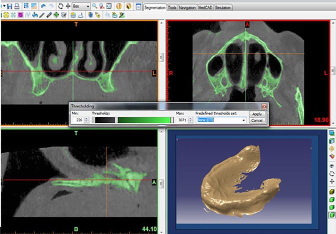
In this study, a three-dimensional model of the bone was designed using CBCT of an old patient by Mimics 10.01 software (Figure 1). In this design, the bone is designed in the form of dual layer: 1-cortical (outer layer) and 2-trabecular (inner layer). The thickness of the cortical layer was considered 0.75 mm and trabecular 11.74 mm since the cortical bone as a compact shell covers the central part of the trabecular bone.
Figure1.
The three-dimensional view of the bone by the Mimics 10.01 software
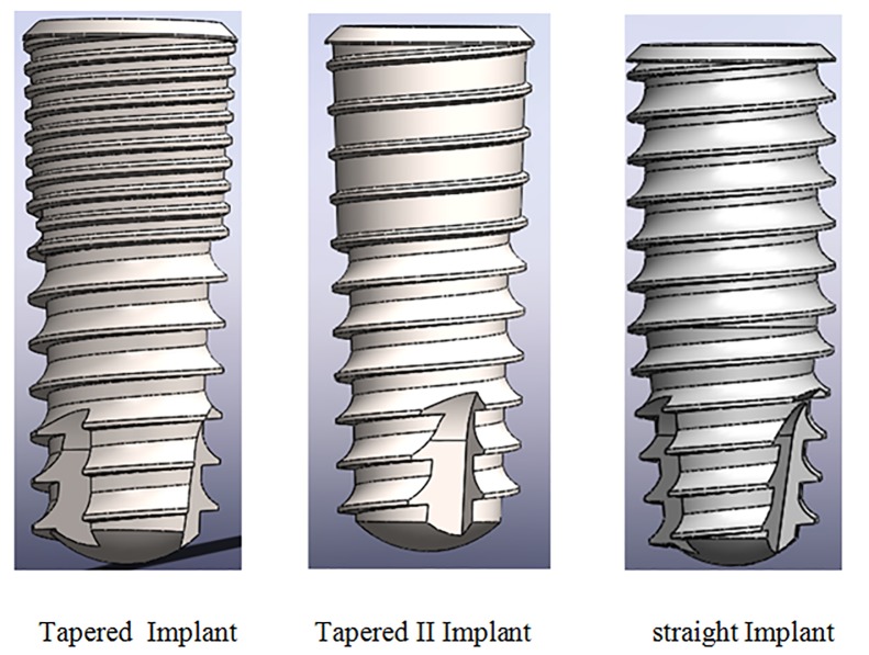
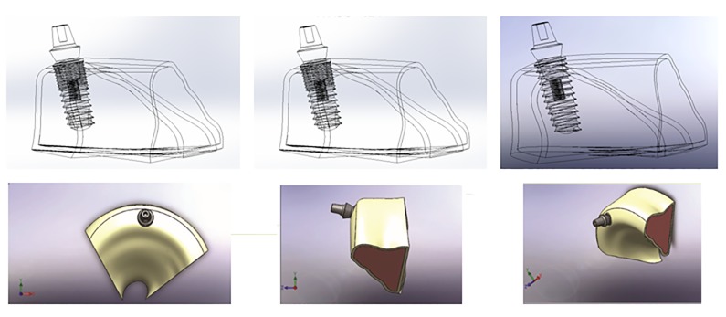
The articles have suggested several methods for implant modeling [1-5]. The modeling of the implant in some studies is in the form of a simple cylinder [2]. Some have used the obtained data of CT scan of patients’ jawbone and transferred them to those from the scan to the software design [8]. The used implants in this study were selected from DENTIS Company (951,Woram-Dong, Dalseo-Gu, Daegu, South Korea). The implants with a length of 10 mm and a diameter of 4.1 mm were used for placing in the jawbone. (Figure 2 and Figure 3).
Figure2.
The implants designed in Solid works software
Figure3.
The placement of the implants and abatement in the bone
The analysis of the finite element
In this study, three different types of implants with various threads and one kind of abutment in the explicit dynamic loading depending on time (impact loading) were studied at the angels of 0° (Axial loading) and 90 ° (Bending loading). First group: Straight implant, second group: Tapered implant, third group: Tapered II implant.
The designed models in the Solid Works software were transferred to ANSYS Work bench 14 software to do the finite element analysis. One of the factors causing differences in the results of various analyses is the characteristics of the materials attributed to different components and geometry.
These materials can be introduced in the form of isotropic, anisotropic and orthotropic. The first step for starting the analysis is importing the data related to the mechanical properties of the materials used in the analysis. In this study, the same as many other articles [9-11], the behavior of all materials such as bone and implant in the form of isotropic and linear elastic have been introduced. The properties of materials such as elastic modulus, the Poisson’s coefficient and density based on Table 1 were defined for this software Table 1.
Table 1.
The mechanical properties of the materials used in the study
| Material | Elastic Moduls (GPa) | Possion Ratio(V) | Density (g/cm-3) |
|---|---|---|---|
| Titanium | 110 | 0.35 | 4.5 |
| Cortical Bone | 1.34 | 0.30 | 0.71 |
| Trabecular Bone | 0.15 | 0.30 | 1.86 |
After transferring the model to the ANSYS software and attribution of the material properties to its different parts, it was meshed uniformly. Identifying the type and size of the elements in an object is the main point of analysis process. Due to the application of tetrahedron three dimensional elements in the objects with complication geometries, in this study the Solid 187 element was used for meshing the different parts.
Solid 187 is a tetrahedral three dimensional element with 10 nodes. Each node in three directions of X, Y, Z can be replaced and because of the existence of 10 nodes, it has a very high ability in matching with figures and compound geometries. This type of element is used for studying the behavior of stress and strain, plastic and hyper-elastic in the complicated geometries and the three dimensional analysis. Noobacky and Sanio used this element for meshing in their study [12,13]
Boundary conditions
The border conditions have a great effect on the distribution of the forces and results. These conditions can be considered as immobile or mobile. The mandible in terms of the border conditions is quite different from the maxilla. In the mandible, the displacement rate is defined in the conditions of being as an abutment because of its mobility and the border conditions for the maxilla have been considered in fixed form.
Loading simulation
The rate and direction of force in different dental models according to the age, gender, type of tooth, etc. are different. In the explicit dynamic analysis to simulate an axial and the bending loading, a rigid body with the speed of 1 mm/s has struck to implant vertically and horizontally (Figures Figure 4 and Figure 5).
Figure4.
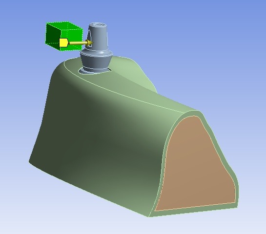
Imposing the bending loading towards the implant
Figure5.
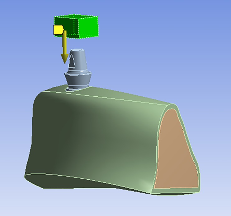
Imposing the axial loading towards the implant
Results
The force imposed on the object is called “impact load” that is exerted within short time. The analysis of the impact load is timely and non-linear. In this study, as the aim was to assess the effects of thread type on the stress distribution of the bone and implant.
Axial Loading Simulation
In the analysis of axial load impact, the maximum imposed stress to the different bone layers as well as the implant can be observed in Table 2. In this regard, the minimum value belongs to the third group and its value is 0.8 MPa and the maximum stress occurred in the first group and its value is 2.4 MPa which is two times more than the stress in the third group.
Table 2.
The maximum amounts of stress imposed on various layers of the bone and implant in the axial loading (MPa)
| Cortical Bone | Trabecular Bone | Implant Titanium | |
|---|---|---|---|
| First group: Straight | 2.4 | 4.3 | 82.1 |
| Second group: Tapered | 0.8 | 8.7 | 187.4 |
| Third group: Tapered II | 0.8 | 6.7 | 85.3 |
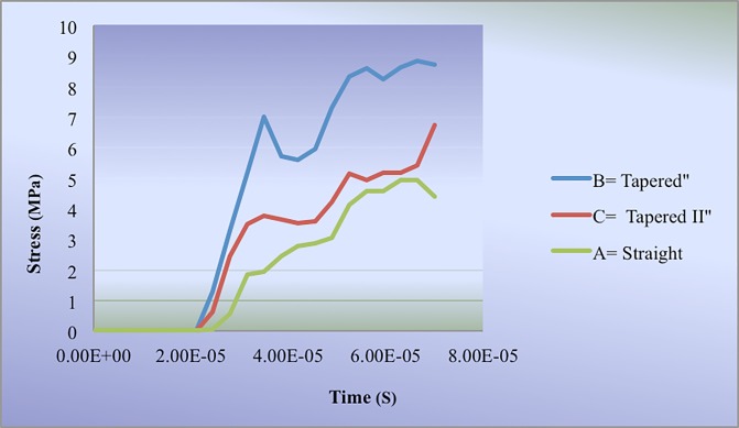
In the axial loading, the maximum stress in trabecular bone occurred in the second group with 8.7 MPa and the minimum amount was observed in the first group with the amount of 4.3 MPa. In the third group the maximum stress in the Trabecular layer was 6.7 MPa (Table 2).
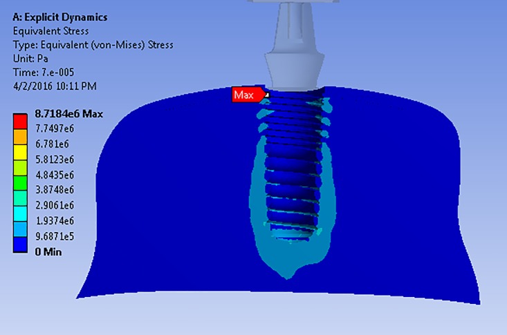
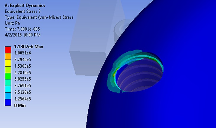
According to the stress distribution pattern on the trabecular bone layer among the analyzed models, the location of maximum amount of stress in the first and third groups was the same: at the lowest part of the implant in the trabecular bone (Figure 6). Nevertheless, in the case of the second group, this location was at the junction of cortical and trabecular bone (Figure 7).
Figure6.
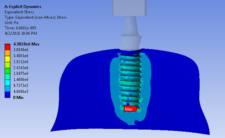
The distribution pattern and place of maximum stress on the trabecular bone layer in the first group
Figure7.
The distribution pattern and place of maximum stress on the trabecular bone in the second group
The behavior and performance of different models of thread and implant system in the trabecular bone layer is shown in Figure 8; according to this figure, the first and third groups showed similar behaviors
Figure8.
Comparison of behavior in various models of thread regarding the stress distribution on the trabecular bone in the axial loading
Bending Loading Simulation
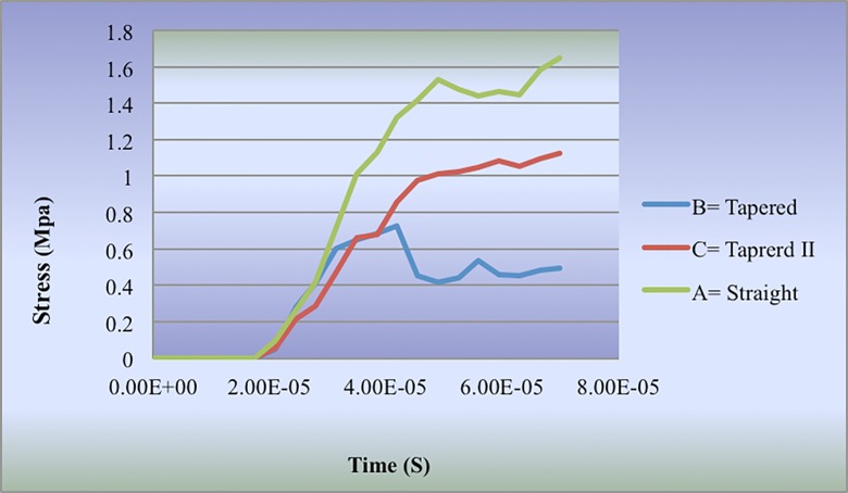
In the horizontal impact analysis, the maximum amount of stress on different layers of the bone as well as the implant is depicted in Table 3. The bending loading of the first group had maximum stress with the amount of 1.6 MPa; also, minimum stress was imposed on the second group with the amount of 0.7 MPa to the cortical bone.
Table 3.
The maximum stress on different layers of the bone and implant under the bending loading
| Cortical Bone | Trabecular Bone | Implant Titanium | |
|---|---|---|---|
| First group: Straight | 1.6 | 5.2 | 75.9 |
| Second group: Tapered | 0.7 | 7.4 | 126.9 |
| Third group: Tapered II | 1.1 | 5.1 | 53.8 |
The third group experienced 1.1 MPa stress on the cortical layer. The stress distribution pattern in this bone layer in all models was the same and its maximum amount was imposed on the first contact area of the implant and bone (Figure 9, Table 3).
Figure9.
The stress distribution pattern on the cortical bone in the bending loading
In the layer of trabecular bone, no significant difference was observed between the imposed stress in the first and third groups, but the second group exerted the maximum stress with the amount of 7.4 MPa.
Regarding the stress distribution pattern between different models of thread, the first and third groups showed a similar pattern and the location of maximum stress in the bending loading was similar to the axial loading at the bottom part of implant (Figure 6).
The stress distribution behavior in various thread groups in the cortical bone is displayed in Figure 10.
Figure10.
The comparison of stress distribution on the cortical bone in bending loading for various thread design
Discussion
The finite element is analyzed in two or three- dimensional form. The choice of two or three- dimensional analysis depends on the complication of the model, the required accuracy rate, application of the results and complication of the structures in the analysis. Based on the results of a study conducted by Meijer, it has been recommended that the two dimensional model should not be used for analysis of the stress on the implant [14]. The difference between modeling in our study and the previous conducted studies is the mode of simulation of software environment with laboratory conditions. In this study, the jaw bone was modeled in an actual form because the figure and geometry of the bone in the mouth and implant system as well as distribution of stress can be effective.
Ozen et al. [15] in their study assessed the effect of various materials on the distribution of stress on the implant by using the three dimensional finite element methods. They recommended that the minimum number of elements and nodes for analyzing the stress of the jaw and implant should be 30000 and 200000, respectively. The dimension at which these numbers of elements and nodes are applied should be taken into account. In our study, because of the implication and presence of various layers, in the design of the analyzed model 725047 elements and 1133167 nodes were applied. Change et al. [16]. in their study assessed the effect of thread deep, figure and length of the cone on the mini implant and found that as the depth of the thread was more, it was more resistance against the exit and replacement.
Schrotenboer et al. [6] conducted a study and concluded that the implants with tiny thread in their neck exert more stress on the bone compared to the implant with smooth neck. The result of the mentioned study is consistent with that of the present study. Abuhussein et al. [2] found that as the contact area of the implant increased, the stress distribution was more desirable; also, when the ability of the bone for maintaining the stability of the implant and the resistance against the stress was weak, using an implant with the deeper thread can resolve this problem.
These results are consistent with those of the current study. Nokar et al. [17] in their study indicated that the cylindrical implant leads to creation of less stress in the contact area of the implant and bone which is in agreement of our current study. Kang et al. [18] in their study of “the effect of implant thread size on its adjacent bone atrophy” used two implants. One was with two types of thread ( a tiny thread above the implant and a bigger one at the bottom of it ) and the other with one type of thread. No significant difference was found between the samples. They found that up to one year after treatment the threads had no any significant effect on the atrophy of the implant’s adjacent bone [18]. Their results were in contrast with that of the present study [18]. They studied two implants with similar conditions but different in the thread step in the upper part of the implant clinically within one year after planting the implant in the jaw. One year after planting the implant, they found that during this time, the type of the threads used has not any acceptable effect on the atrophy rate of the implant’s adjacent bone [18]. While according to the results of present study there was no significant difference between these two types of implant.
Conclusions
Although the real model of the patient’s jaw has been designed in this study and the implants has been modeled with high accuracy, based on engineering principles, choosing the appropriate type of implant is a difficult task. One of the effective parameters that induce stress to the implant, is thread design. In this study the three implant systems were qualified for loading because the level of stress and strain was in acceptable range .Therefore the studied implants could be inserted according to the conditions and the needs of the patient. According to the results of this study the following conclusions are drawn:
1.The implant with smaller threads and the less pitch length leads to an increase of stress on the trabecular bone and implant.
2.Due to increase of its contact area with the bone, the implant with deeper thread, leads to an increase of the implant’s stability.
3.The equal pitch length, but different thread depth, had no significant effect on distribution of stress to the implant’s adjacent bone.
4.The upper thread of the implant which is near the implant neck, in comparison with the lower threads, plays an important role in the distribution of stress; as a result, this part of the design should be more taken into account.
Acknowledgement
Hereby, the authors appreciate Dr. Jafari for their faithful and sincere cooperation.
Conflict of Interest:None declared.
References
- 1.Goodacre JC, Bernal G, Rungcharassaeng K, et al. Clinical complications with implants and implant prostheses. J Prosthet Dent. 2003;90:121–132. doi: 10.1016/S0022-3913(03)00212-9. [DOI] [PubMed] [Google Scholar]
- 2.Abuhussein H, Pagni G, Rebaudi A, et al. The effect of thread pattern implant osseointegration. Clin Oral Implants Res. 2010;21:129–136. doi: 10.1111/j.1600-0501.2009.01800.x. [DOI] [PubMed] [Google Scholar]
- 3.Ausiello P, Franciosa P, Martorelli M, et al. Effects of thread features in osseo-integrated titanium implants using a statistics-based finite element method. Dent Mater. 2012; 28:919–927. doi: 10.1016/j.dental.2012.04.035. [DOI] [PubMed] [Google Scholar]
- 4.Berglundh T, Persson L, Klinge B. A systematic review of the incidence of biological and technical complications in implant dentistry reported in prospective longitudinal studies of at least 5 years. J Clin Periodontol. 2002;29:197–212. doi: 10.1034/j.1600-051x.29.s3.12.x. [DOI] [PubMed] [Google Scholar]
- 5.Watanabe F, Hata Y, Komatsu Sh, et al. Finite element analysis of the influence of implant inclination, loading position, and load direction on stress distribution. Odontology. 2003;9:31–36. doi: 10.1007/s10266-003-0029-7. [DOI] [PubMed] [Google Scholar]
- 6.Schrotenboer J, Tsao YP, Kinariwala V, et al. Effect of microthreads and platform switching on crestal bone stress levels: a finite element analysis. J Periodontol. 2008;79:2166–2172. doi: 10.1902/jop.2008.080178. [DOI] [PubMed] [Google Scholar]
- 7.Ao J, Li T, Liu Y, et al. Optimal design of thread height and width on an immediately loaded cylinder implant: A finite element analysis. Comput Biol Med. 2010;40:681–686. doi: 10.1016/j.compbiomed.2009.10.007. [DOI] [PubMed] [Google Scholar]
- 8.Frisardi G, Chessa G, Barone S, et al. Integration of 3D anatomical data obtained by CT imaging and 3D optical scanning for computer aided implant surgery. BMC Med Imaging. 2011;11:5. doi: 10.1186/1471-2342-11-5. [DOI] [PMC free article] [PubMed] [Google Scholar]
- 9.Hasan I, Bourauel C, Keilig L, et al. The influence of implant number and abutment design on the biomechanical behaviour of bone for an implant-supported fixed prosthesis: a finite element study in the upper anterior region. Comput Methods Biomech Biomed Engin. 2011;14:1113–1116. doi: 10.1080/10255842.2010.515212. [DOI] [PubMed] [Google Scholar]
- 10.Demenko V, Linetskiy I, Nesvit K, et al. Importance of diameter-to-length ratio in selecting dental implants: a methodological finite element study. Comput Methods Biomech Biomed Engin. 2014;17:443–449. doi: 10.1080/10255842.2012.688110. [DOI] [PubMed] [Google Scholar]
- 11.Bin D, Keson BCT, Yi L, et al. Inverse identification of elastic modulus of dental implant–bone interfacial tissue using neural network and FEA model. Inverse Probl Sci Eng. 2009;17:1073–1083. [Google Scholar]
- 12.Sannino G, Pozzi1 A, Schiavetti1 A, et al. Stress distribution on a three-unit implant-supported zirconia framework. a 3rd finite element analysis and fatigue test. Oral & implantol . 2012;5:11–20. [PMC free article] [PubMed] [Google Scholar]
- 13.Okumura N, Stegaroiu R, Kitamura E, et al. Influence of maxillary cortical bone thickness, implants design and implant diameter on stress around implants: A three-dimensional finite element analysis. J Prosthodont Res. 2010;54:133–142. doi: 10.1016/j.jpor.2009.12.004. [DOI] [PubMed] [Google Scholar]
- 14.Meijer HJ, Starmans FJ, Bosman F, et al. A comparison of three finite element models of an edentulous mandible provided two implants. J Oral Rehabil. 1993;20:147–157. doi: 10.1111/j.1365-2842.1993.tb01598.x. [DOI] [PubMed] [Google Scholar]
- 15.Ozen J, Caglar A, Beydemir B, et al. Three dimensional finite element stress analysis of different core materials in maxillary implant supported fixed partial dentures. Quintessence Int. 2007;38:355–363. [PubMed] [Google Scholar]
- 16.Chang JZ, Chen YJ, Tung YY, et al. Effects of thread depth, taper shape, and taper length on the mechanical properties of mini- implant. J Orthod Dentofacial Orthop. 2012;141:279–288. doi: 10.1016/j.ajodo.2011.09.008. [DOI] [PubMed] [Google Scholar]
- 17.Nokar S, Baghai Naini R. Effects of different designs of implant support fixed partial dentures on peri-implant bone stress distribution during mandibular- flexture. J Dent. 2004;17:36–47. [Google Scholar]
- 18.Kang YI, Lee DW, Park KH, et al. Effect of thread size on the implant neck area: preliminary results at 1 year of function. Clin Oral Implants Res. 2011;23:1–5. doi: 10.1111/j.1600-0501.2011.02298.x. [DOI] [PubMed] [Google Scholar]


