Abstract
A rheometer system to measure the rheology of crude oil in equilibrium with carbon dioxide (CO2) at high temperatures and pressures is described. The system comprises a high-pressure rheometer which is connected to a circulation loop. The rheometer has a rotational flow-through measurement cell with two alternative geometries: coaxial cylinder and double gap. The circulation loop contains a mixer, to bring the crude oil sample into equilibrium with CO2, and a gear pump that transports the mixture from the mixer to the rheometer and recycles it back to the mixer. The CO2 and crude oil are brought to equilibrium by stirring and circulation and the rheology of the saturated mixture is measured by the rheometer. The system is used to measure the rheological properties of Zuata crude oil (and its toluene dilution) in equilibrium with CO2 at elevated pressures up to 220 bar and a temperature of 50 °C. The results show that CO2 addition changes the oil rheology significantly, initially reducing the viscosity as the CO2 pressure is increased and then increasing the viscosity above a threshold pressure. The non-Newtonian response of the crude is also seen to change with the addition of CO2.
Keywords: Environmental Sciences, Issue 124, High pressure, rheology, non-Newtonian, crude oil, viscosity, carbon dioxide, shear thinning
Introduction
In most of the literature on the physical properties of CO2 and crude oil mixtures, viscosity is measured using a viscometer, meaning that the measurement is made at a constant shear rate or shear stress. In these studies, the viscosity of CO2 and crude oil mixture is investigated in a simple way: the focus of interest is the relations between the viscosity and other parameters, such as temperature, pressure and CO2 concentration. The key assumption made in these studies, yet rarely mentioned explicitly, is that the CO2 and crude oil mixture behaves as a Newtonian fluid. However, it is well known that some crude oils, especially heavy crude, can show non-Newtonian behavior under certain conditions1,2,3,4. Therefore, to fully understand the CO2 effect, the viscosity of CO2 and crude oil mixture should be studied as a function of shear rate or stress.
To our knowledge, only the study by Behzadfar et al. reports the viscosity of a heavy crude oil with CO2 addition at different shear rates using a rheometer5. In the measurement by Behzadfar et al., the mixing between CO2 and crude oil is achieved by the rotation of the inner cylinder of the coaxial cylinder geometry, a very slow process. In addition, the effect of the CO2 dissolution on the rheology of polymer melts has been reported in the literature, which could shed light on the study of heavy crude oil and CO2 mixtures. Royer et al. measure the viscosity of three commercial polymer melts at various pressures, temperatures and CO2 concentrations, using a high-pressure extrusion slit die rheometer6. They then analyze the data through the free volume theory. Other similar studies can be found in Gerhardt et al.7 and Lee et al.8. Our method, where mixing is performed in an external mixer and the rheology measurement in a coaxial cylinder geometry, allows a more thorough measurement of the rheology of CO2 and crude oil mixture.
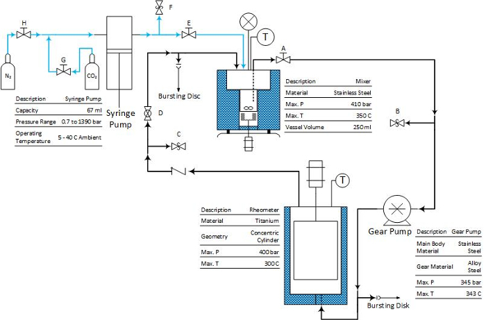
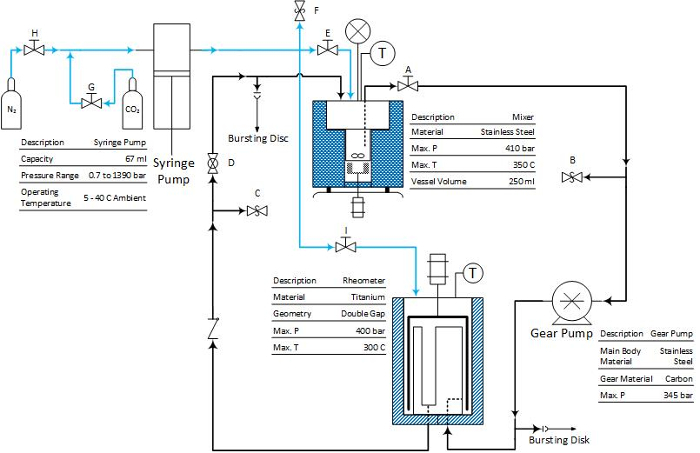
The circulation system that we developed contains four units: a syringe pump, mixer, gear pump and rheometer, as shown in Figure 1 and Figure 2. A stirring bar is placed at the bottom of the mixer and magnetically coupled with a rotating magnet set. Stirring is used to enhance the mixing between CO2 and crude oil in the mixer, speeding up the approach to equilibrium between the phases. The CO2 saturated oil phase is withdrawn from close to the bottom of the mixer using a dip tube and circulated through the measurement system.
The viscosity is measured by a high-pressure cell mounted on a rheometer. There are two types of pressure cells. One is with a coaxial cylinder geometry, which is designed for the measurement of viscous fluid; and the other is with a double gap geometry for low viscosity application.
Figure 1: The scheme of the circulation system with coaxial cylinder geometry pressure cell. The blue line represents CO2 flow, and the black line represents the crude oil mixtures. Reprinted with permission from Hu et al.14. Copyright 2016 American Chemical Society. Please click here to view a larger version of this figure.
Figure 2: The scheme of the circulation system with double gap geometry pressure cell. The blue line represents CO2 flow, and the black line represents the crude oil mixtures. Please click here to view a larger version of this figure.
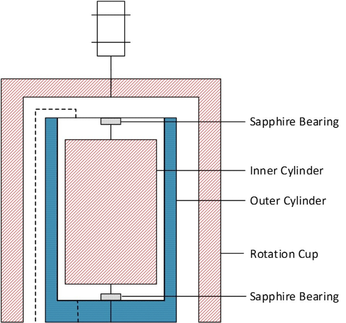
Figure 3: The coaxial cylinder geometry pressure cell. Please click here to view a larger version of this figure.
The coaxial cylinder geometry pressure cell (Figure 3) has a 0.5 mm gap between the inner and outer cylinder, leading to a sample volume of 18 mL. The inner cylinder is magnetically coupled with a rotational cup, which is attached to the rheometer spindle. There are two sapphire bearings at the top and bottom of the inner cylinder, which are directly in contact with the rotation axis of the inner cylinder. Since the sapphire bearings are exposed to the sample by design, the bearing friction may vary according to the lubrication properties of the sample.
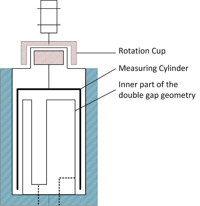
Figure 4: The double gap geometry pressure cell. Please click here to view a larger version of this figure.
On the other hand, the double gap pressure cell comprises a cylindrical rotor in a double gap geometry, as illustrated by Figure 4. The measuring cylinder is mounted on the pressure head through two ball bearings and magnetically coupled with the rotation cup, which is connected to the rheometer spindle. The ball bearings are located inside the pressure head and not in contact with the sample, which is injected into the measurement gap and overflows into a recess in the stator from which it is returned to the mixing vessel.
In a typical experiment, the crude oil sample is first loaded into the mixer. After priming the entire system with the crude oil, the remaining volume in the system is evacuated using a vacuum pump. The CO2 is then introduced into the mixer through the syringe pump and the system brought to the desired temperature and pressure. The system pressure is controlled through the CO2 phase by the syringe pump. When the pressure stabilized, the stirrer is turned on to mix the CO2 and crude oil inside the mixer. Then the gear pump is turned on to withdraw the oil phase from the mixer, fill the rheometer and recycle the fluid back to the mixer. Therefore, the mixing between CO2 and crude oil is done by simultaneously stirring in the mixer and circulating in the loop. The equilibrium status is monitored by periodic measurement of both the volume in the syringe pump and the mixture viscosity. When there is no change (≤4%) in both the volume and viscosity, the equilibrium is confirmed. At that stage the gear pump and stirrer are turned off, suspending the flow through the measurement cell and the rheology measurement is carried out.
Protocol
Note: Since the experiment operates at high temperature and pressure, safety is paramount. The system is protected against over-pressure by the software limit on the syringe pump controller and bursting discs at the mixer and between the gear pump and the rheometer (see Figure 1 and Figure 2). Furthermore, before each experiment, it is recommended to perform a regular leak check. It is also recommended to perform the friction check of the pressure cell geometry to make sure the rheometer is functioning well9,10.
1. Preparing the Crude Oil Sample
NOTE: Use the Zuata crude oil sample as received. The following table shows the basic physical properties of the Zuata crude oil.
| Characteristics | Value |
| API Gravity | 9.28 |
| Barrel Factor (bbl/t) | 6.27 |
| Total Sulphur (% wt) | 3.35 |
| Reid Vapor Pressure (kPa) | 1 |
| Pour Point (°C) | 24 |
| Existing H2S Content (ppm) | - |
| Potential H2S Content (ppm) | 115 |
| Potential HCl Content (ppm) | - |
| Calc. Gross Cal. Value (kJ/kg) | 41,855 |
Table 1: The physical properties of the Zuata crude oil.
Add 128.57 g of toluene to 300 g of Zuata crude oil to prepare the dilution with 70 wt% Zuata crude oil and 30 wt% toluene. Rock the mixture at room temperature for 3 h.
2. Loading the Crude Oil Sample into the Mixer
Disconnect the mixer from the system, and open it up. Place a stirrer at the bottom of the mixer. Load 200 mL of crude oil sample into the mixer. After tightening all the screws, connect the mixer back to the system.
3. Priming the Entire System with the Crude Oil Sample
- Prime the system with the coaxial cylinder geometry pressure cell. NOTE: Please refer Figure 1 to locate the valve.
- Close valves A, D, E, F, G, and H. Open valve C.
- Open the nitrogen cylinder. Introduce the compressed gas into the mixer by opening valves H and E. When the gas reaches the mixer, close valve H and the gas cylinder.
- Open valve A. The compressed gas will push the crude oil sample into the circulation loop through the suction tube. When the crude oil sample is dripping down from valve C in Figure 1, the entire system is primed by the crude oil sample.
- Open valve F to release the remaining gas. Close valve C and open valve D. Turn on the gear pump to circulate the fluid for a while. Depending on the viscosity of the crude oil sample, this could take 1 to 5 h. NOTE: The pressure of the compressed nitrogen introduced into the mixer depends on the viscosity of the crude oil sample. If the viscosity of the crude oil sample is beyond 5 Pa∙s, the pressure of compressed gas may be larger than 15 bar.
- Prime the system with the double gap geometry pressure cell. NOTE: Please refer Figure 2 to locate the valve.
- Remove the pressure head and the measuring cylinder of the pressure cell.
- Close valves A, D, E, F, G, H and I. Open valve C.
- Open the nitrogen cylinder. Introduce the compressed gas into the mixer by opening valves H and E. When the gas reaches the mixer, close valve H and the gas cylinder.
- Open valve A. The compressed gas will push the crude oil sample into the circulation loop through the suction tube. When the crude oil sample just immerse the inner part of the double gap geometry, open valve F to release the pressure in the mixer.
- Turn on the gear pump. Carefully adjust the gear pump rotation speed. Make sure that the inlet flow rate to the pressure cell, which is determined by the gear pump, is less than or equal to the outlet flow rate from the pressure cell, which is determined by gravity. When a reasonable rotation speed of the gear pump is found and the crude oil sample is dripping down from valve C, the entire system is primed by the oil. Then turn off the gear pump.
- Mount the measuring cylinder and pressure head on the pressure cell10. Close valve C and open valve D. Turn on the gear pump to circulate the fluid. NOTE: If the crude oil sample has a viscosity similar to water, the compressed gas with pressure of 3 to 4 bar is enough.
4. Evacuating the Remaining Volume in the System
5. Introducing CO2 into the Mixer
6. Setting the Temperature and Pressure
Input the desired temperature value to the mixer and rheometer. Input the desired temperature value to the heating system of the pipeline network. Input the desired pressure value to the syringe pump.
Wait for the temperature and pressure to stabilize.
7. Turning on the Stirrer and Gear Pump
Open the valves in the downstream and upstream of the gear pump.
8. Monitoring the Volume in the Mixer and the Mixture Viscosity
Record the volume reading in syringe pump for every 6 h.
After every 6 h, turn off the stirrer and gear pump. Measure the viscosity of the mixture through the rheometer. The viscosity measurement starts with a 5 min settling time, and then measure viscosity at constant shear rate of 10 s-1.
When the volume and viscosity values show considerable differences (> 4%) between two consequent measurements, turn on the gear pump and stirrer again to continue the mixing. When both the volume and viscosity measurements show no change in the values (≤ 4%), the equilibrium between the CO2 and crude oil sample is confirmed.
Turn off the gear pump and stirrer for the rheology measurement. NOTE: The mixing period could last for 1 to 2 days, depending on the viscosity of the crude oil sample.
9. Performing the Rheology Measurement
- With coaxial cylinder geometry pressure cell9
- Close valves A and D in Figure 1 for the rheology measurement. Pre-shear the mixture at shear rate of 10 s-1 for 0.5 min. Rest the mixture for 1 min.
- Measure the mixture viscosity at shear rate from 500 s-1 to 10 s-1. At each shear rate, the shear rate adjusting time is 0.2 min. The measurement duration at each shear rate step is logarithmically increased from 0.5 min to 1 min, excluding the shear rate adjusting time.
- With double gap geometry pressure cell10
- Close valves A and D in Figure 2 for the rheology measurement. Pre-shear the mixture at shear rate of 10 s-1 for 0.5 min. Rest the mixture for 1 min.
- Measure the mixture viscosity at shear rate from 250 s-1 to 10 s-1. At each shear rate, the shear rate adjusting time is 0.2 min. The measurement duration at each shear rate step is logarithmically increased from 0.5 min to 1 min, excluding the shear rate adjusting time.
10. Increasing the Pressure to the Next Desired Value
- With the coaxial cylinder geometry pressure cell
- Close valve E in Figure 1.
- Introduce more CO2 into the syringe pump by opening valve G and the CO2 cylinder. Close valve G and the CO2 cylinder. Open valve E to add more CO2 to the mixer.
- If the pressure is less than the desired value, repeat to introduce more CO2.
- Input the new pressure set point into the syringe pump. Wait for the pressure to stabilize.
- With the double gap geometry pressure cell
- Close valves E and I in Figure 2.
- Introduce more CO2 into the syringe pump by opening valve G and the CO2 cylinder. Close valve G and the CO2 cylinder. Open valves E and I to add more CO2 to the mixer.
- If the pressure is less than the desired value, repeat step to introduce more CO2.
- Input the new pressure set point into the syringe pump. Wait for the pressure to stabilize. NOTE: Repeat steps 7 to 10 for the rheology measurement at higher pressures.
Representative Results
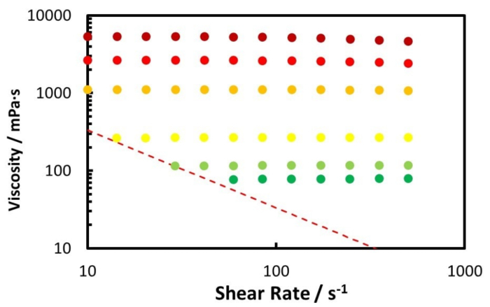
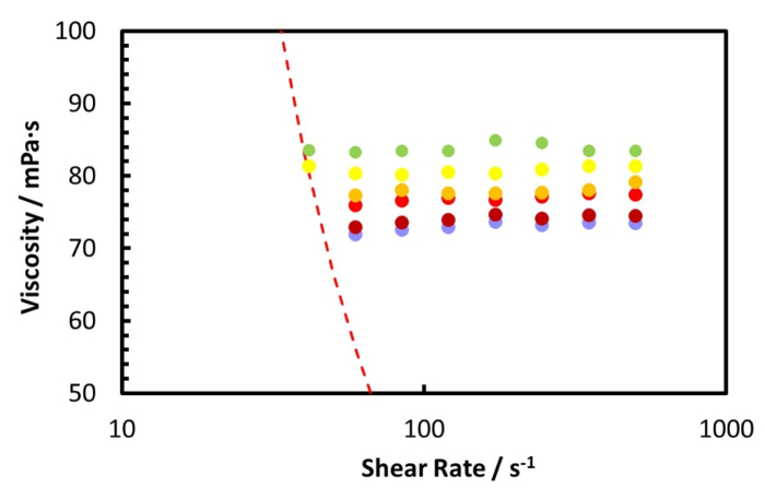
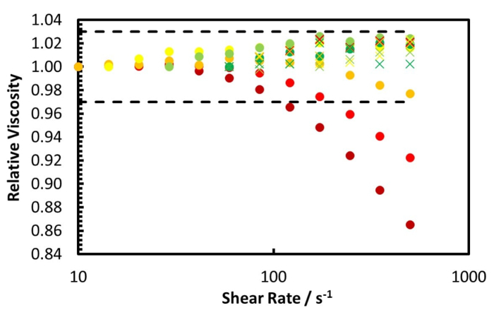
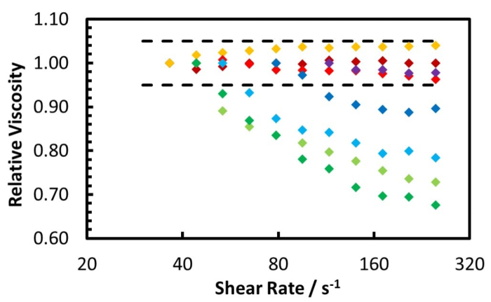
The rheology measurement of the Zuata crude oil and its CO2 saturated mixture, at 50 °C using the coaxial cylinder geometry pressure cell, is shown by Figure 5 and Figure 6. Figure 5 shows the measurement from ambient to 100 bar, while Figure 6 shows the measurement from 120 bar to 220 bar. Furthermore, Figure 7 illustrates the relative viscosity, which is the ratio of the viscosity at a given shear rate to the viscosity at the lowest shear rate. The dashed lines in Figure 7 are the maximum measurement error caused by the friction of the bearings of the geometry.
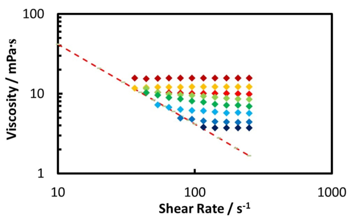
The rheology measurement at 50 °C of the diluted Zuata crude oil, using double gap geometry pressure cell, is illustrated by Figure 8 and Figure 9, while Figure 10 shows the relative viscosity for pressure up to 70 bar. Furthermore, Figure 10 shows that the diluted crude oil at ambient pressure behaves as a Newtonian fluid. However, when the CO2 pressure is from 30 bar to 60 bar, the shear thinning effect is observed. At CO2 pressure above 60 bar, the shear thinning disappears and the mixture behaves as a Newtonian fluid again.
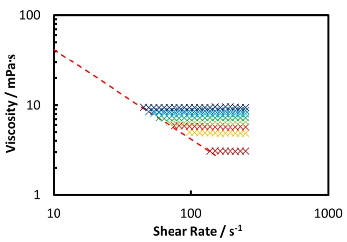
From Figure 5 and Figure 6 one can see that the CO2 dissolution significantly decreases the viscosity of the crude oil mixture until 100 bar. When the CO2 pressure is beyond 100 bar, the oil mixture viscosity increases with increasing CO2 pressure, but at a much lower rate.
Figure 7 reveals that the Zuata crude oil shows a shear thinning effect without CO2 addition. When CO2 is dissolved into the crude oil, the shear thinning effect is weakened, given that the curves at higher CO2 pressures are flatter. At CO2 pressures higher than 40 bar, the viscosity change with shear rate is within the measurement error range, thus the mixture can be considered to be Newtonian. CO2 dissolution weakens and eventually eliminates the shear thinning effect of the Zuata crude oil. This indicates that the CO2 molecule dissolved into the crude oil can eventually disrupt the associating network generated by the macromolecules in the crude oil, such as asphaltenes.
Regarding the diluted crude oil as shown by Figure 8, the CO2 addition dramatically reduces the oil mixture viscosity to a minimum at 70 bar. As the CO2 pressure increases beyond 70 bar (Figure 9), the higher CO2 pressure causes an increase in the oil viscosity.
According to the study by Seifried et al.11, in both the original and diluted Zuata crude oil, the onset of asphaltene precipitation occurs at CO2 pressures above 80 bar. However, in our rheology experiments when the pressure is higher than 80 bar, the crude oil/CO2 mixture behaves as a Newtonian fluid. This implies that asphaltene precipitation does not alter the rheological properties of this mixture.
The rheology results for the diluted crude oil are also interesting: in this case CO2 dissolution gives rise to the non-Newtonian behavior, which only appears in a certain range of CO2 pressure. Two speculations are given here for the shear thinning effect induced by CO2 addition.
The first speculation is that the non-Newtonian behavior is caused by micelles formed by the asphaltene molecules under CO2 dissolution. The CO2 dissolved in the crude oil can reduce the critical micelle concentration (CMC) of the system by its action on the structure of asphaltene aggregates, and this can lead to greater interaction between micelles12. At pressures from 30 to 60 bar, the distance between asphaltene micelles may be within the effective range of the van der Waals attraction force13. Thus, an associating network is formed among the micelles and causes the shear thinning effect. However, when the pressure is above 60 bar, CO2 effect on the solvent or the non-asphaltene molecules is dominating, which leads to increase the CMC. Therefore, the asphaltene micelles are destabilized, and consequentially the associating network disappears.
The second speculation is based on the phase behavior point of view. At CO2 pressures between 30 and 60 bar, a CO2 rich liquid phase may have been generated, which makes the mixture form a liquid-liquid-vapor (LLV) system. An emulsion of these two liquids could be formed through the mixing by stirring and circulation due to the similar density of the two liquid phases. As the dispersed phase of the emulsion, the CO2 rich liquid phase may be stabilized by the asphaltene in the crude oil. This emulsion shows non-Newtonian behavior because the dispersed phase gives rise to an associating network. However, when more CO2 is dissolved into the oil mixture at pressure above 60 bar, the two liquid phases become miscible again. The result is a liquid-vapor (LV) system comprised of a crude oil rich liquid in equilibrium with a CO2 rich vapor and the crude oil rich liquid phase behaves as a Newtonian fluid.
Figure 5. Viscosity measurement for the Zuata heavy crude oil with CO2 at 50 °C and various shear rates. ![]() , lower shear rate limit;
, lower shear rate limit; ![]() , ambient;
, ambient; ![]() , 20 bar;
, 20 bar; ![]() , 40 bar;
, 40 bar; ![]() , 60 bar;
, 60 bar; ![]() , 80 bar;
, 80 bar; ![]() , 100 bar. Reprinted with permission from Hu et al.15. Copyright 2016 American Chemical Society. Please click here to view a larger version of this figure.
, 100 bar. Reprinted with permission from Hu et al.15. Copyright 2016 American Chemical Society. Please click here to view a larger version of this figure.
Figure 6. Viscosity measurement for the Zuata heavy crude oil with CO2 at 50 °C and various shear rates. ![]() , lower shear rate limit;
, lower shear rate limit; ![]() , 120 bar;
, 120 bar; ![]() , 140 bar;
, 140 bar; ![]() , 160 bar;
, 160 bar; ![]() , 180 bar;
, 180 bar; ![]() , 200 bar;
, 200 bar; ![]() , 220 bar. Reprinted with permission from Hu et al.15. Copyright 2016 American Chemical Society. Please click here to view a larger version of this figure.
, 220 bar. Reprinted with permission from Hu et al.15. Copyright 2016 American Chemical Society. Please click here to view a larger version of this figure.
Figure 7. The relative viscosity for the Zuata crude oil with CO2 at 50 °C and various shear rates. – –, measurement fluctuation range; ![]() , ambient pressure;
, ambient pressure; ![]() , 20 bar;
, 20 bar; ![]() , 40 bar;
, 40 bar; ![]() , 60 bar;
, 60 bar; ![]() , 80 bar;
, 80 bar; ![]() , 100 bar;
, 100 bar; ![]() , 120 bar;
, 120 bar; ![]() , 140 bar;
, 140 bar; ![]() , 160 bar;
, 160 bar; ![]() , 180 bar;
, 180 bar; ![]() , 220 bar. Reprinted with permission from Hu et al.15. Copyright 2016 American Chemical Society. Please click here to view a larger version of this figure.
, 220 bar. Reprinted with permission from Hu et al.15. Copyright 2016 American Chemical Society. Please click here to view a larger version of this figure.
Figure 8. Viscosity measurement for the diluted crude oil with CO2 at 50 °C and various shear rates. ![]() , lower shear rate limit;
, lower shear rate limit; ![]() , 1 bar;
, 1 bar; ![]() , 10 bar;
, 10 bar; ![]() , 20 bar;
, 20 bar; ![]() , 30 bar;
, 30 bar; ![]() , 40 bar;
, 40 bar; ![]() , 50 bar;
, 50 bar; ![]() , 60 bar;
, 60 bar; ![]() , 70 bar. Please click here to view a larger version of this figure.
, 70 bar. Please click here to view a larger version of this figure.
Figure 9. Viscosity measurement for the diluted crude oil with CO2 at 50 °C and various shear rates. ![]() , lower shear rate limit;
, lower shear rate limit; ![]() , 80 bar;
, 80 bar; ![]() , 100 bar;
, 100 bar; ![]() , 120 bar;
, 120 bar; ![]() , 140 bar;
, 140 bar; ![]() , 160 bar;
, 160 bar; ![]() , 180 bar;
, 180 bar; ![]() , 200 bar;
, 200 bar; ![]() , 220 bar. Please click here to view a larger version of this figure.
, 220 bar. Please click here to view a larger version of this figure.
Figure 10. The relative viscosity for the diluted crude oil with CO2 at 50 °C and various shear rates. – –, measurement fluctuation range; ![]() , 1 bar;
, 1 bar; ![]() , 10 bar;
, 10 bar; ![]() , 20 bar;
, 20 bar; ![]() , 30 bar;
, 30 bar; ![]() , 40 bar;
, 40 bar; ![]() , 50 bar;
, 50 bar; ![]() , 60 bar;
, 60 bar; ![]() , 70 bar. Please click here to view a larger version of this figure.
, 70 bar. Please click here to view a larger version of this figure.
Discussion
Two steps are critical in the operation. The first one is priming the entire system by the crude oil sample. By filling up the system with the crude oil sample, the gear pump can be well lubricated by the oil sample, and any blockages in the circulation loop can be easily identified. Thus the gear pump can be prevented from damage. The second critical step is periodically monitoring the mixture viscosity to confirm the equilibrium between the CO2 and crude oil. Given that it takes a considerable amount of time to reach the equilibrium between CO2 and viscous heavy crude oil16, performing the rheology measurement too early will underestimate the effect of CO2 addition on the oil viscosity. Therefore, only when the viscosity measured reaches a constant value (less than 4% change), can the mixture be considered in equilibrium with CO2.
The current measurement system only allows the rheology measurement of the CO2 saturated mixture. To measure under-saturated mixtures, an upstream vessel could be introduced to the CO2 stream. The CO2 will be introduced to the upstream vessel first and then isolated from the source, so that the amount of CO2 can be controlled by the volume and pressure in the upstream vessel. The total pressure of the system in this case would be controlled by an inert gas, such as helium. Kariznovi et al. provides a good review on the apparatus used to measure the physical properties of CO2 and heavy crude oil mixture17. Modifications can refer to the systems that reviewed in their paper.
It should be mentioned that the system described here can measure the rheology of any gas-liquid mixtures; therefore its application is not limited to crude oils. For example, it can be used to measure the CO2 effect on the rheology of Pickering emulsions18,19 and gas-induced plasticization6. By introducing the electrical conductivity measurement device into the rheometer pressure cell, the effect of gas dissolution on the shear-induced phase inversion of emulsions could also be studied20,21,22,23.
Disclosures
The authors have nothing to disclose.
Acknowledgments
The authors gratefully acknowledge funding from the Qatar Carbonates and Carbon Storage Research Centre (QCCSRC), provided jointly by Qatar Petroleum, Shell, and Qatar Science and Technology Park. The authors thank Frans van den Berg (Shell Global Solutions, Amsterdam, Netherlands) for providing the crude oil sample.
References
- Hasan SW, Ghannam MT, Esmail N. Heavy crude oil viscosity reduction and rheology for pipeline transportation. Fuel. 2010;89(5):1095–1100. [Google Scholar]
- Henaut I, Barre L, Argillier JF, Brucy F, Bouchard R. Rheological and Structural Properties of Heavy Crude Oils in Relation With Their Asphaltenes Content. SPE International Symposium on Oilfield Chemistry. 2013. pp. 13–16.
- Ghannam MT, Hasan SW, Abu-Jdayil B, Esmail N. Rheological properties of heavy & light crude oil mixtures for improving flowability. J. Petrol. Sci. Eng. 2012;81:122–128. [Google Scholar]
- Martínez-Palou R, et al. Transportation of heavy and extra-heavy crude oil by pipeline: A review. J. Petrol. Sci. Eng. 2011;75(3-4):274–282. [Google Scholar]
- Behzadfar E, Hatzikiriakos SG. Rheology of bitumen: Effects of temperature, pressure, CO2 concentration and shear rate. Fuel. 2014;116(0):578–587. [Google Scholar]
- Royer JR, Gay YJ, Desimone JM, Khan SA. High-pressure rheology of polystyrene melts plasticized with CO2: Experimental measurement and predictive scaling relationships. J. Polym. Sci., Part B: Polym. Phys. 2000;38(23):3168–3180. [Google Scholar]
- Gerhardt LJ, Manke CW, Gulari E. Rheology of polydimethylsiloxane swollen with supercritical carbon dioxide. J. Polym. Sci., Part B: Polym. Phys. 1997;35(3):523–534. [Google Scholar]
- Lee M, Park CB, Tzoganakis C. Measurements and modeling of PS/supercritical CO2 solution viscosities. Polym. Eng. Sci. 1999;39(1):99–109. [Google Scholar]
- CC29/Pr Pressure Cell Operation. Anton Paar. 2014. Available from: http://www.anton-paar.com/us-en/products/details/pressure-cell/
- DG35.12/Pr Pressure Cell Operation. Anton Paar. 2014. Available from: http://www.anton-paar.com/us-en/products/details/pressure-cell/
- Seifried C, Hu R, Headen T, Crawshaw J, Boek E. IOR 2015-18th European Symposium on Improved Oil Recovery. Eage. 2015.
- Priyanto S, Mansoori GA, Suwono A. Measurement of property relationships of nano-structure micelles and coacervates of asphaltene in a pure solvent. Chem. Eng. Sci. 2001;56(24):6933–6939. [Google Scholar]
- Zhao Y, et al. Effect of compressed CO2 on the properties of lecithin reverse micelles. Langmuir. 2008;24(17):9328–9333. doi: 10.1021/la801427b. [DOI] [PubMed] [Google Scholar]
- Hu R, Trusler JPM, Crawshaw JP. The effect of CO2 dissolution on the rheology of a heavy oil/water emulsion. Energy Fuels. 2016.
- Hu R, Crawshaw JP, Trusler JPM, Boek ES. Rheology and Phase Behavior of Carbon Dioxide and Crude Oil Mixtures. Energy Fuels. 2016.
- Zhang YP, Hyndman CL, Maini BB. Measurement of gas diffusivity in heavy oils. J. Petrol. Sci. Eng. 2000;25(1-2):37–47. [Google Scholar]
- Kariznovi M, Nourozieh H, Abedi J. Experimental apparatus for phase behavior study of solvent-bitumen systems: A critical review and design of a new apparatus. Fuel. 2011;90(2):536–546. [Google Scholar]
- Tang J, Quinlan PJ, Tam KC. Stimuli-responsive Pickering emulsions: recent advances and potential applications. Soft Matter. 2015;11(18):3512–3529. doi: 10.1039/c5sm00247h. [DOI] [PubMed] [Google Scholar]
- Aveyard R, Binks BP, Clint JH. Emulsions stabilised solely by colloidal particles. Adv. Colloid Interface Sci. 2003;100:503–546. [Google Scholar]
- Kawashima Y, Hino T, Takeuchi H, Niwa T, Horibe K. Rheological Study of W/O/W Emulsion by a Cone-and-Plate Viscometer - Negative Thixotropy and Shear-Induced Phase Inversion. Int. J. Pharm. 1991;72(1):65–77. [Google Scholar]
- Perazzo A, Preziosi V, Guido S. Phase inversion emulsification: Current understanding and applications. Adv. Colloid Interface Sci. 2015;222:581–599. doi: 10.1016/j.cis.2015.01.001. [DOI] [PubMed] [Google Scholar]
- Yeo LY, Matar OK, de Ortiz ESP, Hewitt GF. Phase Inversion and Associated Phenomena. Multiphase Sci Technol. 2000;12(1) [Google Scholar]
- Liu L, Matar OK, de Ortiz ESP, Hewitt GF. Experimental investigation of phase inversion in a stirred vessel using LIF. Chem. Eng. Sci. 2005;60(1):85–94. [Google Scholar]


