Abstract
The chemical bonding of particulate photocatalysts to supporting material surfaces is of great importance in engineering more efficient and practical photocatalytic structures. However, the influence of such chemical bonding on the optical and surface properties of the photocatalyst and thus its photocatalytic activity/reaction selectivity behavior has not been systematically studied. In this investigation, TiO2 has been supported on the surface of SiO2 by means of two different methods: (i) by the in situ formation of TiO2 in the presence of sand quartz via a sol-gel method employing tetrabutyl orthotitanium (TBOT); and (ii) by binding the commercial TiO2 powder to quartz on a surface silica gel layer formed from the reaction of quartz with tetraethylorthosilicate (TEOS). For comparison, TiO2 nanoparticles were also deposited on the surfaces of a more reactive SiO2 prepared by a hydrolysis-controlled sol-gel technique as well as through a sol-gel route from TiO2 and SiO2 precursors. The combination of TiO2 and SiO2, through interfacial Ti-O-Si bonds, was confirmed by FTIR spectroscopy and the photocatalytic activities of the obtained composites were tested for photocatalytic degradation of NO according to the ISO standard method (ISO 22197−1). The electron microscope images of the obtained materials showed that variable photocatalyst coverage of the support surface can successfully be achieved but the photocatalytic activity towards NO removal was found to be affected by the preparation method and the nitrate selectivity is adversely affected by Ti-O-Si bonding.
Keywords: Chemistry, Issue 125, Supported TiO2, Photocatalysis, NOx, Nitrate selectivity, environmental pollution, air quality
Introduction
Concrete structures are ubiquitous in our society. Typically associated with our urban centers, their significant surface area represents an important interface with the urban atmosphere 1,2. With increasing concerns over the economic and health impacts of deteriorating urban air quality this interface presents an important opportunity for atmospheric remediation. TiO2-based photocatalysts have been utilized for some time in the remediation of NOx-contaminated air, and their support on these high surface area concrete structures offers concrete the additional functionality previously associated with photocatalytic materials: (i) easy-cleaning, whereby materials which bind dirt to surfaces are photocatalytically degraded enabling dirt to readily wash off with rain water 3; (ii) photo-induced hydrophilicity, which also enhances the self-cleaning effect 3; and (iii) purification of the urban atmosphere which today, is typically polluted by vehicle emissions at levels that significantly exceed maximum permissible levels, particularly with respect to NOx4. TiO2 is the most commonly employed photocatalyst in environmental applications due to its chemical stability, relatively low price, high photocatalytic activity, and more importantly its eco-safety as indicated by currently available TiO2 toxicology data 5.
Photocatalytic concretes have already demonstrated their potential for atmospheric remediation on trial sites throughout Europe and elsewhere. Numerous studies on photocatalytic cementitious materials over the last two decades have predominantly dealt with catalyst activity, often expressed in terms of NOx concentration reduction1,6,7,8,9. However, activity alone is an insufficient indicator of photocatalytic effectiveness. A reduction in NOx concentration, defined as the sum of the concentrations of the atmospheric nitrogen oxides, does not by itself represent a useful impact on air quality because the relative toxicities of the constituent gases are not equivalent 10.
Photocatalytic oxidation of NOx gases follow the sequence
NO → HONO → NO2 → HONO2 (NO3-)
The higher toxicity of NO2 relative to NO (by, conservatively a factor of 310), means that the oxidative conversion of NO through to nitrate (i.e. the nitrate selectivity) must be maximized. Consequently, the means to deliver both high activities and high nitrate selectivities must be targeted.
As for catalysis in general, high surface areas are required for the adsorption of reacting molecules. Nanoparticulate TiO2 ensures the high specific surface area required for high photocatalytic activity provided particles are adequately dispersed9. However, when applied to concretes by mixing into the cement binder, agglomeration can occur, reducing effective surface area, and cement hydration reactions can lead to photocatalyst occlusion, reducing accessible surface area further and blocking the catalyst from activating sunlight1,11.
Significantly improved performance can therefore be expected when accessible catalyst surface area is better preserved in more efficient photocatalytic structures. These have included catalysts supported on concrete surface exposed aggregates and in zeolite structures2,12. The durability of these structures depends very much on how well bound the catalyst is to the various supports. The benefits of chemically bonding TiO2 to substrates have often been referred to in the literature8,13 but the means of characterizing the degree of binding has been ambiguous. Nevertheless, the integrity of a chemical bond relative to a physical attraction presents an opportunity to develop robust structures on the surface of the concrete. However, the influence of a chemical bond between TiO2 and a substrate, e.g. quartz, to provide a Ti-O-Si linkage, on the optical and photocatalytic properties of the supported TiO2 has not previously been studied. Therefore, the focus of the present work has been in establishing means to generate and quantify levels of Ti-O-Si linkages and to correlate these with the photocatalytic properties of the supported TiO2. For this purpose, commercial as well as synthesized TiO2 have been bonded, by different methods, onto quartz SiO2 sand (Q; as a simple example of an aggregate).
Protocol
1. Synthesis of TiO2-SiO2 Composites
- Samples based on commercial quartz NOTE: Quartz, with particles sizes in the range 20 - 100 µm was obtained by ball milling commercial quartz for 15 min and sieving. The powders were then modified with TiO2 by two different methods.
- QT1
- Prepare a 10% solution of titanium(IV) butoxide (TBOT; 97%) in ethanol as a TiO2 precursor9 by dissolving TBOT (2.6 mL) in ethanol (29.6 mL).
- Suspend 3 g of quartz powder in 30 g of the freshly prepared titanium precursor solution by continuous stirring.
- Add 0.3 mL of hydrochloric acid (32%). Stir the resulting suspension for 5 min.
- Add 30 mL of deionized water and continuously stir the mixture overnight.
- Transfer all of the viscous suspension to a Petri dish and store under ambient conditions until the solvent has completely evaporated.
- Wash the treated quartz with deionized water several times and then dry at 90 °C overnight.
- Heat-treat at 400 °C for 20 h.
- Cool the powders in air and sieve again to collect particles bigger than 20 µm. This was to separate modified quartz from loosely or non-connected TiO2.
- QT2 NOTE: Support commercial photocatalyst (PC105) on quartz via a silica gel binder derived from tetraethyl orthosilicate (TEOS) as follows.
- Prepare a TEOS mother solution by dissolving TEOS (23.2 mL) in ethanol (29.2 mL). Then add deionized water (7.2 mL) and HCl (0.4 mL; 3.6 wt.%) to get final ethanol:water:HCl mixture (1:0.84:0.78 x 10⁻³ molar ratio). Stir the mixture for 10 days at room temperature.
- Add accurate volumes of the obtained solution to 100 mL of ethanol, in which 0.2 g TiO2 were suspended, to get TiO2:TEOS of 1:1.
- Stir gently at room temperature overnight and then add the suspension dropwise to 2 g of quartz with continuous stirring at 80 °C under reduced pressure.
- Dry the obtained powders at 90 °C overnight followed by heat treatment at 200 °C for 4 h.
- Samples based on synthesized silica
- ST1 NOTE: Deposit TiO2 nanoparticles on the surfaces of precipitated SiO2 prepared by a hydrolysis-controlled sol-gel technique.
- Synthesize monodisperse silica microspheres via the Stoeber-Bohn-Fink method14.
- Dissolve TEOS (5 mL) in ethanol (40 mL) and stir for 30 min (solution A).
- Prepare solution B by mixing ammonia solution (8 mL; 25 wt.%) with deionized water (30 mL) and ethanol (18 mL) with continuous stirring for 30 min.
- Quickly add all of solution A to solution B and stir at room temperature for 3 h.
- Collect the resulting SiO2 by centrifugation (1,252 x g). Wash 3 times with absolute ethanol and dry at 105 °C for 48 h.
- Prepare a suspension of the produced SiO2 by suspending 1 g in 30 mL of ethanol in an ultrasonic bath for 10 min. Stir the suspension for a further 30 min.
- Carefully add 1 mL of TBOT (97%) to the ethanolic SiO2 suspension.
- Age the mixture at room temperature under stirring for 24 h.
- Add deionized water (2 mL) and ethanol (8 mL) and then stir the mixture further for 2 h.
- Collect the modified powder by centrifugation and wash 3 times with ethanol. Dry at 105 °C for 48 h followed by heat treatment at 500 °C for 3 h. NOTE: T1: For comparison, TiO2 was prepared by the same method but in the absence of silica.
- ST2 NOTE: In these samples, synthesize homogeneous gel of SiO2/TiO2 molar ratio 0.25 from stoichiometric mixtures of tetraethyl orthosilicate (TEOS) and titanium tetraisopropoxide (TTIP) as precursors for Si and Ti, respectively as follows.
- Add the required amount of TEOS (0.89 mL) dropwise into an ethanol:water:HCl mixture (73.6 mL; 1:0.84:0.78 x 10⁻³ molar ratio).
- Stir at room temperature for 1 h.
- Add the desired amount of TTIP (4.74 mL) and stir the mixture further at room temperature overnight.
- Achieve sol-gel conversion by stirring at 80 °C for 1 h.
- Heat treat the obtained gel as follows: overnight drying at 90 °C, 450 °C for 5 h, and 500 °C for 5 h. NOTE: T2: Pure TiO2 was also prepared by the same sol-gel method but in the absence of TEOS.
2. Characterization
Record IR spectra using a spectrophotometer equipped with UATR (Single Reflection Diamond)15.
Obtain X-ray diffraction (XRD) patterns using a PAN analytical diffractometer equipped with a CuKa1 1.54 Å X-ray source16.
Analyze the morphology of the samples via scanning electron microscopy (SEM), equipped with ED X-ray analyzer and BSE detector with operating voltage between 10 - 20 kV. Use energy dispersive X-ray analysis and capture images with a Digital Image Acquisition System.
Perform transmission electron microscopy (TEM) on a microscope operated with an accelerating voltage of 200 kV. Capture images with a camera.
Record UV-Vis diffuse reflectance spectra of the samples using a UV-Vis spectrophotometer equipped with fiber optic coupler. Use barium sulphate as reference in the range of 250 to 600 nm. Transform the resulting reflectance spectra into apparent absorption spectra by using the Kubelka−Munk function F (R∞) = (1 − R∞)2/2R∞17.
3. Photocatalytic Performance Test
- Test the photocatalytic activities of the prepared materials using the removal of NOx from polluted air test18.
- For this purpose, establish an air-purification test set-up (see Figure 1) consisting of gas supplies, humidifier (2), gas flow controllers (1), photocatalytic reactor (3), UV(A) light source (4) and NOx analyzer (5). The gas supplies were NO (100 ppm) in N2, and synthetic air( BOC).
- Use mass flow controllers (1) to provide NO at 1 ppmv (0.5 ppmv, for ST1 and T1 samples) and the relative humidity to ca. 40%, confirmed by Rotronic hygropalm, to the laminar flow reactor (3) at a volume flow of 5 x 10⁻⁵ m3*s-1 (1.675 x 10⁻⁵ m3*s-1 in the case of ST1 and T1 samples).
- Construct the photoreactor from PMMA (Poly(methyl methacrylate)) and cover by borosilicate glass. Position it below the output from an SS0.5 kW, 500 W fully reflective solar simulator equipped with a 1.5 AM filter to ensure that the test sample (6) received a light intensity of 10 Wm-2 at λ <420 nm, as measured by a broadband thermopile detector.
- Monitor the concentrations of NO, NO2 and total NOx in the outlet gas flow using a NO-NO2-NOx Analyzer.
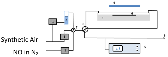
Figure 1:The Experimental Set-up Used for the Photocatalytic Tests: (1) mass flow controllers (2) humidifier (3) photocatalytic reactor (4) UV(A) light source (5) NOx analyzer (6) test sample (7) and (8) valves, and (9) gas stream outlet. Please click here to view a larger version of this figure.
- Prepare test samples by pressing 0.8 g (0.3 g in the case of ST1 and T1 samples) of the material into a rectangular PMMA holder (height 0.2 cm, width 3 cm, and length 8 cm).
- Irradiate the resulting briquettes with a geometric surface area of 2.4 × 10⁻³ m2 overnight with UV (320 nm) to remove any organic contaminants adsorbed on their surfaces.
Representative Results
X-ray diffraction (XRD) XRD patterns of uncoated quartz sand (Q), the prepared TiO2-SiO2 composites and TiO2 in the absence of quartz are shown in Figure 2. The peak positions confirm the presence of anatase in the TiO2 only sample as well as in the TiO2-SiO2 composites, except for the preparation at 400 °C (QT1) where no clear TiO2 peaks are observed. In the other cases, the differences between the different samples in peak intensities and widths are due to the differences in particle sizes and degree of crystallinity. For QT1, the lack of TiO2 peaks may be attributed to either a low degree of crystallinity or to a very low amount of TiO2 loaded on quartz under these preparation conditions. However, transmission electron microscopy (Figure 3) shows QT1 to be decorated with nanoparticulate TiO2 particles, which, under high magnification, are shown to be agglomerated nanospheres.
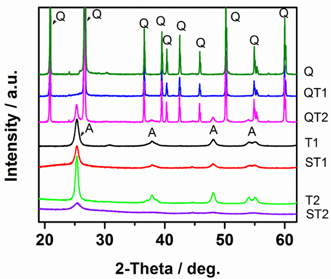
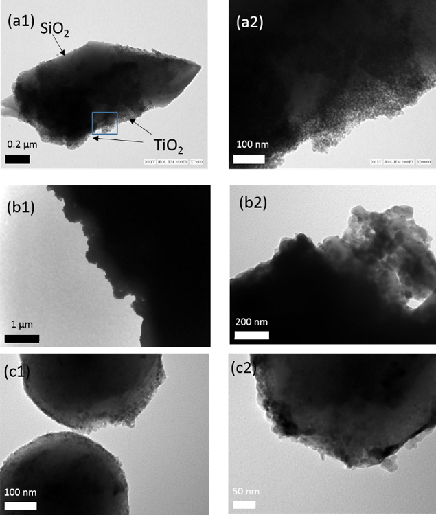
Figure 2: XRD Patterns of Pure TiO2 and TiO2-SiO2 Composites Prepared by Different Methods. Please click here to view a larger version of this figure.
Figure 3:TEM Images of the Titania-coated SiO2 Samples;(a) QT1 (b) QT2 and (c) ST1 in low (1) and high (2) magnification images. Please click here to view a larger version of this figure.
Diffuse reflectance spectroscopyFigure 4 shows the UV-vis absorption spectra of the prepared samples, expressed as the modified Kubelka-Munk function [F(R∞)hν]1/2, plotted as a function of incident photon energy as required for an indirect semiconductor. The spectra are also consistent with the presence of TiO2 and show that TiO2 loading on the surface of SiO2 has negligible effect on the band gap. However, a small shift to higher energy level (ca. 3.3 eV) is observed for the mixed oxides sample (ST2) indicating a band gap widening effect.
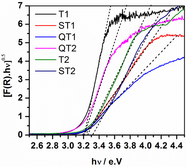
Figure 4: Transformed Diffuse Reflectance Spectra (Tauc plots) for TiO2 and TiO2-SiO2 Composites. Please click here to view a larger version of this figure.
Fourier Transform Infrared Spectroscopy (FTIR)Figure 5 shows the FTIR spectra of the SiO2/TiO2 mixed oxides samples and of the TiO2-Q composites. Evidence for the chemical binding of TiO2 to SiO2 may be observed in the range between 900 - 960 cm-1 assignable to the Si-O-Ti stretching vibrational mode15; as expected, no absorption peak due to this mode was observed for SiO2 or TiO2.
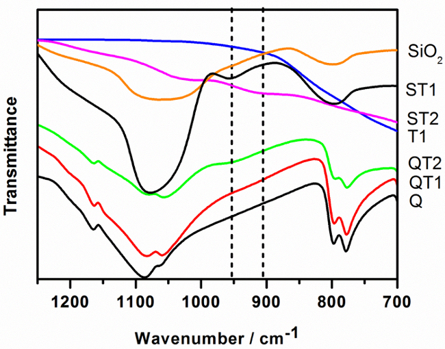
Figure 5:FTIR Spectra of TiO2 (T1), SiO2, Reactive Silica Modified with TiO2 (ST1), SiO2-TiO2 Mixed Oxide Prepared via Sol-gel Method (ST2), Quartz (Q) and TiO2-modified Quartz Samples (QT1, QT2). For clarity, the spectrum for T2 is not shown but it is identical to T1. Please click here to view a larger version of this figure.
TiO2-quartz composites Although molecular modeling by Tokarsky et al.16 indicated the possibility of Ti-O-Si on sand quartz, they were not able to observe clear evidence for Ti-O-Si experimentally following thermal hydrolysis of titanyl sulphate in the presence of quartz. However, as can be seen from Figure 5, a very low IR absorption can be noticed in the range 920 - 960 cm-1 for comparable QT1 composites in this study indicating a small amount of Ti-O-Si bonding. QT2 exhibits more significant absorbance likely to be associated with the interaction of TiO2 with more reactive TEOS coating the quartz surface. It is likely that the TiO2 is associated with the resulting silicate-based gel rather than the quartz surface.
Mixed oxide systems The highest FTIR absorption measured in this study was observed for ST2, derived from the reaction of organic precursors. Such a system is expected to maximize the dispersion and mixing of reactants which is consistent with the FTIR data. ST1 utilized a pre-precipitated silica but despite its reactive surface, the resulting FTIR absorption indicates a relatively low level of bonding.
Scanning electron microsocopy (SEM) The effectiveness of a silicate-based film on quartz (QT2) for the efficient support of TiO2 has been examined by SEM. Much depends on how well the film itself coats the quartz substrate. Figure 6 compares the SEM-EDS of commercial TiO2 (PC105) dispersed within this film derived from TEOS with TiO2 in a 1:1 molar ratio (QT2). The silicate film was found to have been immobilized inhomogenously on the grains as some areas remain clear of the silicate coating. Consequently, in this case, TiO2, associated with the silicate-based gel phase, is also inhomogeneously distributed and is not bonded directly to the quartz surface. This is consistent with the TEM image in Figure 3 b(2). The silicate coating (top right of image) gives an EDS analyses comparable with that reported in Figure 6(d) indicating the association of TiO2 with the silicate layer.
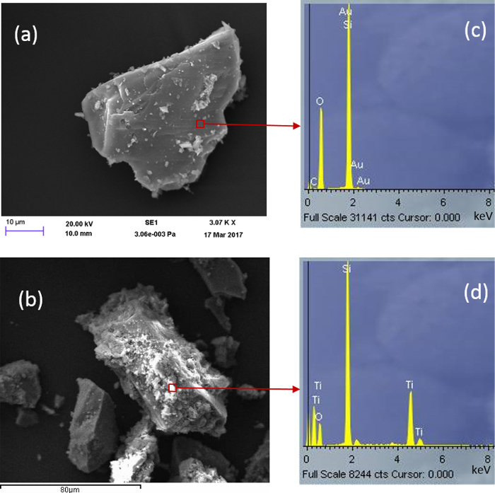
Figure 6:SEM Images for (a) Bare Quartz and (b) Sample QT2. Corresponding EDS data are presented in c and d respectively. Please click here to view a larger version of this figure.
Photocatalytic performance
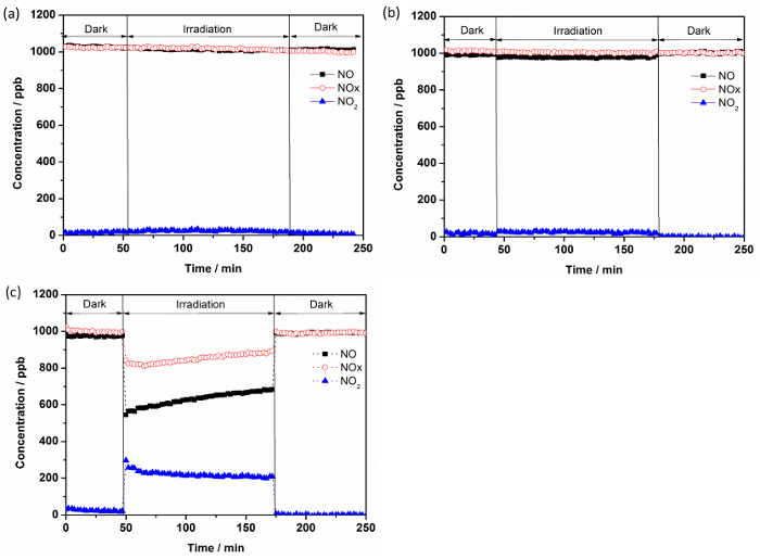
Figure 7 shows an example of the changes in the concentrations of NO, NOx, and NO2 in the gas stream flows over TiO2 (PC105) in the dark and under illumination. When light was switched on, the initial NO concentration drops by ca. 48% with a simultaneous formation of NO2. Consequently, the concentration of NOx, which expresses mainly the sum of the NO and NO2 concentrations, is reduced during illumination time.
The proposed conversion pathway of NO after its adsorption on illuminated TiO2-based photocatalyst can be summarized in the following scheme:
NO → HONO → NO2 → HONO2 (NO3-)
It can also be noticed from Figure 7 that the concentration of NO increased slightly and continuously during the entire irradiation time. This illustrates an approach to the steady state condition and can be attributed to the accumulation on the available active sites of photocatalytically generated NO oxidation products, i.e., HNO2/NO2-; NO2; and HNO3/NO3-, which may influence NO adsorption rates. Bloh et al. reported that achieving a steady-state in this system requires several hours of illumination.
Figure 7: Concentration Variations for NO, NO2, and NOx as a Function of Time:(a) without any photocatalyst or support (b) quartz only, and (c) PC105. Please click here to view a larger version of this figure.
To determine and compare the activities of the obtained TiO2-SiO2 composites for NOx abatement, the photonic efficiencies (ξ) for the removal of NO, NOx and the formation of NO2 was calculated and illustrated in Figure 8.
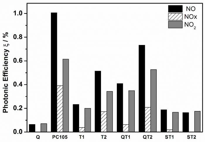
Figure 8:Photonic Efficiencies of Different TiO2 and TiO2-SiO2 Composite Powders for NO and NOx Removal and for NO2 Formation. Directly comparable systems are identified with the same symbols, supported vs non-supported pairs. Please click here to view a larger version of this figure.
ξ is defined as the ratio of the reaction rate and the incident photon flux and was calculated according to Eq.(9)18, where ![]() is the volumetric flow rate; cd the concentration of NO, NOx, or NO2 under dark conditions; ci the concentration of the same gas under illumination; p the pressure; NA the Avogadro constant; h is the Plank constant; c is the speed of light; I the incident irradiation intensity, λ the employed wavelength assuming monochromatic light (365 nm), A the irradiated area; R the gas constant; and T the absolute temperature.
is the volumetric flow rate; cd the concentration of NO, NOx, or NO2 under dark conditions; ci the concentration of the same gas under illumination; p the pressure; NA the Avogadro constant; h is the Plank constant; c is the speed of light; I the incident irradiation intensity, λ the employed wavelength assuming monochromatic light (365 nm), A the irradiated area; R the gas constant; and T the absolute temperature.
 (9)
(9)
Discussion
Figure 8 shows quite significant differences between the NO photonic efficiencies for each of the photocatalytic materials. The advantages of supporting the photocatalyst to increase accessibility to reactive surface is now well established and it is worth noting the difference between the photonic efficiencies for NO oxidation measured for PC105 and for PC105 supported on treated quartz (QT2). ξ NO (QT2) was measured at 73% of that for PC105 but QT2 had only 6.5% of the TiO2 loading. Clearly, activity improvements are significant on supported systems but care should be applied when interpreting measurements with significant morphological differences.
A key characteristic of the photocatalytic test system which can be expected to influence the measurement is the surface texture of the sample supported in the photocatalyst reactor. This influences the effective surface area. The calculation of ξ includes an area term but this is a two-dimensional area of illumination defined by the reactor sample holder. The particle size distribution of TiO2 powders, i.e. PC105, T1 and T2, are quite different from the composites, where TiO2 'powder' is supported on SiO2 of diameter in the range 0.4-50 μm. This means that the photocatalyst surface textures are quite variable and are expected to influence the reported photonic efficiencies. It also influences reactor flow characteristics. The rougher the texture, due to packing characteristics, the more likely that the laminar flow regime required is disrupted. This is expected to influence rates of gas molecule diffusion to surface and consequently the photonic efficiency measurement.
As a consequence of these effects, the most useful comparison of photocatalyst types must be based on properties derived from measurements on individual catalysts. In this study, nitrate selectivity, which is based on ξ NO and ξ NO2 (Equation 10), both measured on the same sample are used in subsequent discussion.
 (10)
(10)
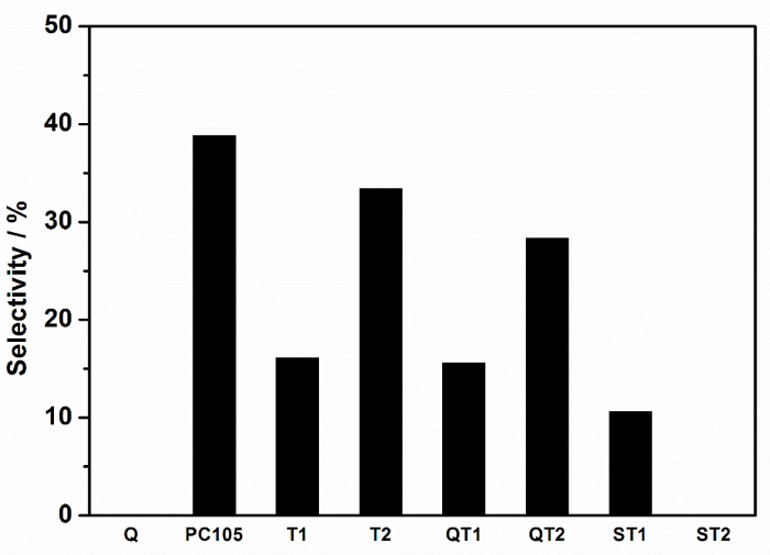
Figure 9: Selectivity Towards the Total Removal of NOx, i.e., Nitrate Selectivity, Recorded for Different TiO2 and TiO2-SiO2 Composite Powders. Directly comparable systems are identified with the same symbols, supported vs non-supported pairs. Please click here to view a larger version of this figure.
The factors which control nitrate selectivity appear to be complex and relevant variables include TiO2 polymorphism, defect state, availability of water, etc.7, but the role of substrate binding, often considered to be advantageous to photocatalytic performance, can now also be considered. It is beneficial therefore to discuss the nitrate selectivity differences between non-bonded and bonded systems, i.e. stand-alone photocatalyst vs photocatalyst-support composites, e.g. PC105 vs QT2; where QT2 represents PC105 supported in a silicate coating on quartz. These nitrate selectivity differences are summarized in Table 1.
| Photocatalyst | Photocatalyst-support | DSelectivity (%); (relative selectivity reduction (%)) | FTIR peak area ratio; (Ti-O-Si) /SiO2 | Ti-O-Si peak centre (cm-1) |
| PC105 | QT2 | (38.8-28.3) = 10.5; (-27) | 0.0088 | 960 |
| T1 | ST1 | (16.0-10.6) = 5.4; (-34) | 0.0184 | 960 |
| T2 | ST2 | (33.4-0) = 33.4; (-100) | 0.6566 | 920 |
| T1 | QT1 | (16.0-15.6) = 0.4; (-3) | 0.0014 | 930 |
Table 1: Influence of Composite Formation and Ti-O-Si Bonding on Photocatalyst Performance. Background corrected FTIR peak areas for peaks assigned to Ti-O-Si (920 - 960 cm-1) and for SiO2 (990 - 1230 cm-1) were obtained from Figure 5 using Origin Peak Analyses software. The dimensionless area ratio indicated in Table 1 is taken as a measure of the degree of Ti-O-Si bonding in composite systems. Also shown are the peak center positions associated with the Ti-O-Si linkage. These data are summarized in Figure 10.
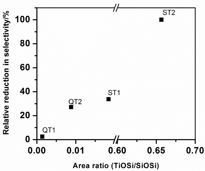
Figure 10: Relative Reduction in Nitrate Selectivity for Different TiO2 Materials Combined with SiO2 as a Function of Ti-O-Si Bonding in Photocatalyst-support Composites. Please click here to view a larger version of this figure.
The greatest selectivity reduction on composite formation, i.e. that which would show the largest negative impact on ambient air quality, is indicated for photocatalyst T2 when it is combined with a silicate precursor. A highly dispersed gel is produced in which Ti-O-Si linkages are maximized. The peak area analyses indicates that around 65 mole % of the TiO2 is associated with SiO2 through Ti-O-Si connections, which is approaching the stoichiometric TiO2:SiO2 ratio of the preparation (80%) and providing confidence in the peak area ratio analysis. It is also noteworthy that the Ti-O-Si peak center is located at the lowest wavenumber observed for the composites and suggests that compositional information may be embedded in the Ti-O-Si peak characteristics. All other composites display considerably lower (Ti-O-Si)/SiO2 peak area ratios, indicating lower levels of Ti-O-Si bonding. Figure 10 shows that this level of bonding is correlated with Selectivity, expressed as a percentage reduction from the free standing catalyst selectivity, indicating that Ti-O-Si binding has a negative impact on photocatalytic NOx abatement.
The consequences of these findings are that a compromise must be met to ensure the physical durability of a bonded system without a significant loss of photocatalytic performance. Possible approaches could include: (i) increasing the supported TiO2 particle size such that the beneficial Ti-O-Ti bonding, which defines the intrinsic photocatalytic properties of 'stand-alone' photocatalysts, are not diluted by the Ti-O-Si linkages, and/or (ii) engineering a thin, porous and durable surface coatings for the substrate such that the photocatalyst is trapped in pores accessible to reactant gas molecules and illumination.
Silica in the form of quartz sand or reactive silica spheres has been successfully modified with TiO2 either via binding commercial TiO2 photocatalyst (PC105), utilizing a silicate-based binder or via the hydrolysis-condensation reactions of different Ti precursors. The photocatalytic performance of the resulting composites has been compared with that of a sol-gel derived mixed oxide system promoting high levels of Ti-O-Si binding linkages. The key findings show that: (i) the degree of TiO2-SiO2 binding in the mixed oxide preparation is high (65%) as expected and approaches the stoichiometric TiO2:SiO2 ratio in the preparation. This composite gel system displayed no nitrate selectivity compared with the comparable sol-gel derived TiO2 (T2) which showed a selectivity of 33%, (ii) as the reactivity of the silicate surface reduces, the degree of Ti-O-Si binding reduces; the order is reactive silica spheres (ST1) > silicate gel layer on quartz (QT2) > bare quartz, and (iii) the nitrate selectivity of TiO2 is adversely affected by the level of Ti-O-Si bonding.
Disclosures
Authors have nothing to disclose.
Acknowledgments
The authors gratefully acknowledge funding from the UK Engineering and Physical Sciences Research Council (Grant Ref: EP/M003299/1) and the Natural Science Foundation of China (No. 51461135005) International Joint Research Project (EPSRC-NSFC).
References
- Folli A, et al. Understanding TiO2 Surface Chemistry to Control and Modulate Photocatalytic Performances. J Am Ceram Soc. 2010;93(10):3360–3369. [Google Scholar]
- Wang FZ, Yang L, Sun GX, Guan LY, Hu SG. The Hierarchical Porous Structure of Substrate Enhanced Photocatalytic Activity of TiO2/Cementitious Materials. Constr Build Mater. 2014;64:488–495. [Google Scholar]
- Fateh R, Dillert R, Bahnemann D. Preparation and Characterization of Transparent Hydrophilic Photocatalytic TiO2/SiO2 Thin Films on Polycarbonate. Langmuir. 2013;29(11):3730–3739. doi: 10.1021/la400191x. [DOI] [PubMed] [Google Scholar]
- Dillert R, Engel A, Grosse J, Lindner P, Bahnemann DW. Light Intensity Dependence of the Kinetics of the Photocatalytic Oxidation of Nitrogen(II) Oxide at the Surface of TiO2. Phys Chem Chem Phys. 2013;15:20876–20886. doi: 10.1039/c3cp54469a. [DOI] [PubMed] [Google Scholar]
- Shi HB, Magaye R, Castranova V, Zhao JS. Titanium Dioxide Nanoparticles: A Review of Current Toxicological Data. Part Fibre Toxicol. 2013;10 doi: 10.1186/1743-8977-10-15. [DOI] [PMC free article] [PubMed] [Google Scholar]
- Freitag J, et al. Nitrogen(II) Oxide Charge Transfer Complexes on TiO2: A New Source for Visible-Light Activity. J Phys Chem C. 2015;119(9):4488–4501. [Google Scholar]
- Ma JZ, Wu HM, Liu YC, He H. Photocatalytic Removal of NOx over Visible Light Responsive Oxygen-Deficient TiO2. J Phys Chem C. 2014;118(14):7434–7441. [Google Scholar]
- Mendoza C, Valle A, Castellote M, Bahamonde A, Faraldos M. TiO2 and TiO2-SiO2 Coated Cement: Comparison of Mechanic and Photocatalytic Properties. Appl Catal B-Environ. 2015;178:155–164. [Google Scholar]
- Kamaruddin S, Stephan D. Sol-gel Mediated Coating and Characterization of Photocatalytic Sand and Fumed Silica for Environmental Remediation. Water Air Soil Poll. 2014;225:1948. [Google Scholar]
- Bloh JZ, Folli A, Macphee DE. Photocatalytic NOx Abatement: Why the Selectivity Matters. Rsc Adv. 2014;4 [Google Scholar]
- Macphee DE, Folli A. Photocatalytic Concretes - the Interface Between Photocatalysis and Cement Chemistry. Cement Concrete Res. 2016;85:48–54. [Google Scholar]
- Yang L, et al. The Influence of Zeolites Fly Ash Bead/TiO2 Composite Material Surface Morphologies on Their Adsorption and Photocatalytic Performance. Appl Surf Sci. 2017;392:687–696. [Google Scholar]
- Pinho L, Elhaddad F, Facio DS, Mosquera MJ. A Novel TiO2-SiO2 Nanocomposite Converts a Very Friable Stone into a Self-Cleaning Building Material. Appl Surf Sci. 2013;275:389–396. [Google Scholar]
- Stöber W, Fink A, Bohn E. Controlled Growth of Monodisperse Silica Spheres in Micron Size Range. J Colloid Interf Sci. 1968;26(1):62–69. [Google Scholar]
- Yamashita H, et al. Characterization of Titanium-Silicon Binary Oxide Catalysts Prepared by the Sol-Gel Method and Their Photocatalytic Reactivity for The Liquid-Phase Oxidation of 1-Octanol. J Phys Chem B. 1998;102(30):5870–5875. [Google Scholar]
- Tokarský J, et al. A Low-Cost Photoactive Composite Quartz Sand/TiO2. Chem Eng J. 2013;222:488–497. [Google Scholar]
- Beranek R, Kisch H. Tuning the optical and photoelectrochemical properties of surface-modified TiO2. Photochem Photobiol Sci. 2008;7(1):40–48. doi: 10.1039/b711658f. [DOI] [PubMed] [Google Scholar]
- Kisch H, Bahnemann D. Best Practice in Photocatalysis: Comparing Rates or Apparent Quantum Yields? J Phys Chem Lett. 2015;6(10):1907–1910. doi: 10.1021/acs.jpclett.5b00521. [DOI] [PubMed] [Google Scholar]


