Abstract
Suspensions of healthy and pathological red blood cells (RBC) flowing in microfluidic devices are frequently used to perform in vitro blood experiments for a better understanding of human microcirculation hemodynamic phenomena. This work reports the development of particulate viscoelastic analogue fluids able to mimic the rheological and hemorheological behavior of pathological RBC suspensions flowing in microfluidic systems. The pathological RBCs were obtained by an incubation of healthy RBCs at a high concentration of glucose, representing the pathological stage of hyperglycaemia in diabetic complications, and analyses of their deformability and aggregation were carried out. Overall, the developed in vitro analogue fluids were composed of a suspension of semi-rigid microbeads in a carrier viscoelastic fluid made of dextran 40 and xanthan gum. All suspensions of healthy and pathological RBCs, as well as their particulate analogue fluids, were extensively characterized in steady shear flow, as well as in small and large amplitude oscillatory shear flow. In addition, the well-known cell-free layer (CFL) phenomenon occurring in microchannels was investigated in detail to provide comparisons between healthy and pathological in vitro RBC suspensions and their corresponding analogue fluids at different volume concentrations (5% and 20%). The experimental results have shown a similar rheological behavior between the samples containing a suspension of pathological RBCs and the proposed analogue fluids. Moreover, this work shows that the particulate in vitro analogue fluids used have the ability to mimic well the CFL phenomenon occurring downstream of a microchannel contraction for pathological RBC suspensions. The proposed particulate fluids provide a more realistic behavior of the flow properties of suspended RBCs when compared with existing non-particulate blood analogues, and consequently, they are advantageous for detailed investigations of microcirculation.
I. INTRODUCTION
The behavior of separated, washed, and resuspended red blood cells (RBC), also called erythrocytes, flowing through microfluidic devices has been studied for several years. This blood element is the most concentrated component in blood and is the main cause of its non-Newtonian behavior at low shear rates, where the blood viscosity is high due to the formation of RBC agglomerates known as rouleaux. At high shear rates, the disruption of the agglomerates and consequent alignment of the deformable cells lead to a reduction of the viscosity (shear-thinning). The orientation of the RBCs at high shear rates and their tendency to migrate to the center line of the microchannels (in vitro)1–3 or microvessels (in vivo)4,5 originate the formation of a cell depleted layer near the walls, known as the cell-free layer (CFL). The CFL is influenced by the formation of aggregates, cell interactions and deformability, hematocrit, flow rate, viscosity, and geometry6,7 and is a microscopic level phenomenon that occurs in microfluidic devices2,6,8,9 and in microvessels10–12 with dimensions in the range of 300 μm down to 10 μm. Several studies have been performed both in vivo11,13,14 and in vitro2,9,15–18 to better understand the CFL formation, which influences its thickness and the advantages and disadvantages of the presence of this layer in the human microcirculatory system6 and in microchannels.8,16,19 It is also important to refer that in real blood, there is a migration of white blood cells from the core towards the wall region of the vessels, a phenomenon called margination,20,21 but this issue is outside the scope of this work. Additionally, it is also known that CFL is influenced by the presence of several pathological disorders that also change the rheological properties of whole blood22,23 as is the case of diabetic disorders.
Diabetes mellitus is a metabolic disorder that reduces the effects of insulin on the human body because either the pancreas is unable to produce enough insulin (type 1 diabetes) or the body is resistant to the effects of insulin and in addition it does not produce enough insulin to maintain a normal glucose level (type II diabetes). As a result, when the glucose concentration increases in the bloodstream, or hyperglycemia, we have a condition that can affect people with both type I and type II diabetes. The high concentration of glucose in plasma causes alterations in the lipid-protein interactions and consequent glycation of erythrocyte protein membranes, resulting in a decrease in RBC deformability and changes in their shape, leading to the formation of flat or discocyte cells. As a consequence, there is an increase in the internal viscosity of RBCs due to structural alterations in the hemoglobin molecule and also an enhancement of aggregate formation that increases the blood viscosity.24,25 Hyperglycemia is the most important factor on the onset, and the progress of diabetic complications and untreated hyperglycemia can cause long-term complications.
Hyperglycemia in diabetes was observed in several studies where the reduction in the RBC deformability and the increase in the aggregation level were found to promote the enhancement of the CFL thickness.22,23,26 The most frequently used in vitro experiment to study this pathological disorder involves the incubation of healthy RBCs in high glucose concentrations as a model to mimic in vivo conditions of hyperglycemia in diabetes. This approach has been successfully used for a better understanding of RBC mechanical modifications and in particular the investigation of the impairment of microcirculation in diabetic patients.22,23,27–29 In this work, we have also applied this method to obtain pathological suspensions of RBCs due to the difficulty in acquiring and handling pathological blood. Hence, it is crucial to develop blood analogues that are able to mimic the hemodynamic and hemorheological properties not only of healthy but also of the pathological blood behavior. Mimicking pathophysiological behavior of the RBCs will be helpful to understand several pathological phenomena since working with blood, and in particular, with pathological blood, continues to raise ethical, economical, and safety issues. To the best of our knowledge, this is the first attempt to develop two-phase in vitro analogue fluids that mimic the behavior of RBC suspensions at in vitro conditions equivalent to the pathological in vivo stage of hyperglycaemia, a condition that occurs at diabetic complications.
Several authors have already proposed blood analogues that have a good agreement with whole blood in terms of rheological properties, especially under steady shear conditions. Such studies were performed with Newtonian blood analogues composed of mixtures of glycerol and water,30–34 and others have used non-Newtonian fluids composed of an aqueous solution of xanthan gum (XG) or/and polyacrylamide (PAA), diluted in water or/and glycerine.35,36 Campo-Deaño et al.37 have successfully developed whole blood analogues based on sucrose and dimethylsulfoxide with XG having viscosity curves and viscoelastic moduli similar to whole human blood and in addition demonstrated that these analogues are suitable to be used in polydymethylsiloxane (PDMS) microfluidic devices due to their refractive index matching. However, in vitro blood flow experiments have shown that it is crucial to take into account the blood elements,1,2,15 in particular when in vitro flow studies intend to investigate microcirculation phenomena occurring at hematocrits of about 20%–25%. For instance, Lima and co-workers1,2 have visualized and measured cell–cell interactions, and they have shown that RBC radial dispersion tends to increase with cell concentration and may influence the blood mass transport mechanisms. Hence, it is important hemodynamic flow phenomena that occur at the microscale also be mimicked by particulate blood analogue fluids.
To date, there are very few works where particulate blood analogue fluids, i.e., a base fluid containing solid suspended elements, have been proposed, and none of those are capable of mimicking the blood element behavior. Maruyama et al.38,39 have developed a blood analogue made of a Newtonian solvent containing a suspension of microcapsules to evaluate the absolute hemolytic properties of centrifugal blood pumps. Later, Nguyen et al.40 have performed a similar study, although this time by using a non-Newtonian solvent. These latter studies present particulate blood analogues that are able to reproduce well the steady viscosity, but they did not study any microscale flow phenomenon. An exception is the preliminary study by Calejo et al.41 where constant and non-Newtonian continuous phases with suspended particles were used to perform CFL flow studies in a PDMS microchannel. Their results have shown that the CFL originated from the particles depends strongly on the base fluid, but otherwise further developments and improvements are needed to mimic blood flow phenomena occurring at the microcirculation level.
The main objective of this work is to develop in vitro analogue fluids able to mimic the rheological properties of suspended pathological in vitro RBCs and also hemorheological flow phenomena occurring in PDMS microchannels such as the CFL formation downstream of a contraction. The proposed particulate analogue fluids are composed of a carrier fluid made of 115 ppm (w/w) of XG diluted in dextran 40 and with suspended semi-rigid microbeads with a diameter of 10 μm, a dimension close to the size of human RBCs, at weight concentrations of 5% and 20%. Non-Newtonian properties of the developed analogues and of the RBC suspensions were investigated by performing both steady and oscillatory shear flow tests. Additionally, to analyse the ability of the proposed analogue fluids to mimic the flow behavior of pathological in vitro RBCs suspensions, flow visualizations were performed in microchannels. The CFL measurements obtained for the suspension of RBCs were compared with the CFL thickness obtained by the corresponding analogue fluid.
The remainder of this paper is organized as follows: Section II comprises several subsections to explain the experimental framework around blood samples, analogue fluids preparation, and the setups used to acquire the rheological data and to perform the flow visualizations. Section III presents and discusses the results, and the main conclusions are provided in Sec. IV.
II. MATERIALS AND METHODS
A. Healthy and glucose-rich blood samples preparation
Whole blood samples were collected into tubes with an anticoagulant (ethylenediaminetetraacetic acid) from a healthy human donor, and the RBCs were separated from the plasma and buffy coat by centrifugation. Then, RBCs were resuspended and washed twice with phosphate buffer saline (PBS). To obtain the healthy fluids with the desired hematocrit (Hct) of 5% and 20% by volume, after washing, the RBCs were suspended in dextran 40 (Dx 40). Dextran 40 has a density of 1042 kg/m3 and a constant viscosity of 5.2 mPa.s at 20 °C and is commonly used in experimental studies as a substitute of blood plasma (ρ = 1021 kg/m3) since it minimizes the sedimentation of blood cells during the experiments and reduces cell clogging.19 The experiments of the blood flow and measurements of blood rheology were immediately performed after blood preparation.
To obtain the pathological RBCs, we have performed a twelve hour incubation of the washed erythrocytes in a highly concentrated glucose solution at 37 °C. The glucose incubation medium was prepared by diluting 100 mM of glucose in PBS. A normal blood glucose level in non-diabetic humans (as our healthy donor), before a meal, is about 5 mM, so 100 mM represents a very high glucose concentration.25,28 After the incubation time, the RBCs were washed twice with PBS in order to remove any remaining traces of the glucose-rich medium. Finally, we resuspended the glucose-rich RBCs at the desired Hct in Dx 40 to perform all the experiments.
B. Preparation of the analogue fluids
The particulate analogue fluids used in this study were composed of polymethylmethacrylate (PMMA) microbeads with a diameter of 10 μm, which have a similar dimension to human erythrocytes. The microbeads were suspended at the same concentration as the RBCs (5% and 20% by weight) in Dx 40 and in the viscoelastic developed base fluid. The viscoelastic base fluid was composed of 115 ppm (w/w) of xanthan gum (XG) diluted in Dx 40. More information of the fluid preparation and composition can be found in the study by Calejo et al.41 A summary of all the fluids used in this study can be found in Table I.
TABLE I.
Working fluids used in the experimental studies and the corresponding mass concentrations used (cell concentrations by volume and PMMA microbeads by weight).
| Suspended medium | Dx 40Dx 40 + 115 ppm XG |
| Blood fluids | Dx 40 + RBCs (5%) |
| Dx 40 + Glucose-rich RBCs (5%) | |
| Dx 40 + RBCs (20%) | |
| Dx 40 + Glucose-rich RBCs (20%) | |
| Two-phase fluids with a constant viscosity continuous phase | Dx 40 + PMMA (5%) |
| Dx 40 + PMMA (20%) | |
| Two-phase fluids with a variable viscosity continuous phase | Dx 40 + 115 ppm XG + PMMA (5%) |
| Dx 40 + 115 ppm XG + PMMA (20%) | |
| Deformability assessments | Dx 40 + RBCs (1%) |
| Dx 40 + Glucose-rich RBCs (1%) | |
| Dx 40 + 115 ppm XG + PMMA (1%) |
Deformability tests were also performed for 1% (w/w) of PMMA microbeads suspended in the viscoelastic base fluid. For the deformability assessments, we have decided to use 1% of microbeads and RBCs in order to obtain clear images of individual elements passing through the hyperbolic contraction to reduce possible image analysis errors.
C. Fluid rheology
The rheological measurements in steady-state and small amplitude oscillatory shear (SAOS) flows were carried out by means of a stress-controlled rheometer (Bohlin CVO, Malvern, Worcestershire, UK) using a 55 mm diameter cone-plate geometry with a gap of 30 μm. According to Mezger,42 a gap size 5 times larger than the biggest particle size is recommended, and in a more restrictive way, Schramm43 recommends a gap size 3 times larger than the diameter of the particle. Hence, the gap (30 μm) used in this study was three times larger than the dimensions of the particles (more details can be found in the supplementary material). Steady shear flow curves were obtained in a range of shear rates of 1 ≤ ≤ 10000. The SAOS measurements were performed in a frequency range of 0.01 to 100 rad/s, after identifying the range of amplitudes in which the elastic moduli (G′ and G″) behaved linearly. All the measurements were carried out at 20 °C, and at least three replicates in each measurement were made in order to corroborate the reproducibility.
The large amplitude oscillatory shear (LAOS) measurements were performed with a plate-plate geometry with a diameter of 50 mm and a gap of 1 mm, using a stress-controlled rheometer from Anton Paar model Physica MCR-301. The measurements were achieved using a direct strain oscillation module (DSO) by applying a strain amplitude sweep at an imposed frequency of 0.1 and 1 rad/s. From the LAOS tests, we quantified the minimum and large strain elastic moduli, G′M and G′L, respectively, and the minimum-rate and large-rate dynamic viscosities η′M and η′L by following the framework described by Ewoldt et al.44 We also quantified the strain-stiffening (S) and shear-thickening (T) ratios measured using the same framework (MITlaos version 2.2 beta for Matlab, freeware provided by MITlaos@mit.edu).44 These nonlinear viscoelastic properties are well described in the literature by Ewoldt et al.,44,45 Läuger and Stettin,46 and Sousa et al.47
D. Experimental setup and image analysis
1. Deformability analysis
Deformability tests were carried out for healthy and glucose-rich RBCs to observe and quantify the influence of the high glucose concentration on the RBC deformability by using a high-sensitivity microfluidic tool having a microchannel with a hyperbolic-shaped contraction.9 Similar measurements were also carried out for the analogue fluid, i.e., PMMA microbeads at 1% (w/w) suspended in the viscoelastic base fluid. These latter results were compared with data obtained from the healthy and glucose-rich RBCs deformability tests.
To observe and analyse the behavior of the RBCs and the particulate analogue viscoelastic fluid flowing through the PDMS microchannels with hyperbolic-shaped contractions, a high-speed video microscopy system was used. This system consists of an inverted microscope (IX71, Olympus, Japan) combined with a high-speed camera (Fastcam SA3, Photron, USA). The PDMS microchannel was placed and fixed on the plate of the microscope, and the flow rate of the working fluids was kept constant by means of a syringe pump (PHD Ultra, Harvard Apparatus, USA) and a 1 ml syringe (Terumo, Japan). For the deformability experiments, flow rates of 1 and 3 μl/min were used, and the images were captured at a rate of 3000 frames/s with a shutter speed ratio of 1/75 000 to minimize the dragging of the cells and microbeads at high flow rates. All the flow experiments were performed at room temperature (T = 20 ± 2 °C).
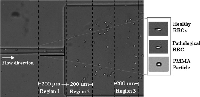
The recorded images were evaluated by means of the image analysis software ImageJ (NIH)48 and by a similar procedure to that used by Pinho et al.8 and Rodrigues et al.19 Figure 1 shows the geometry of the microchannel and the regions where the deformation measurements were taken for all the cells and microbeads. All regions were 200 μm long (see Fig. 1), and the major () and minor () dimensions of the cells or PMMA particles passing through the regions were measured and their deformation index () was calculated by using the following equation:
| (1) |
FIG. 1.
Representation of the hyperbolic-shaped contraction followed by a sudden expansion used to assess the deformability measurements with the selected Regions 1, 2, and 3.
More detailed information about the cell deformability behavior when flowing through a hyperbolic-shaped contraction microchannel can be found in the study by Yaginuma et al.17
2. Cell-free layer (CFL) analysis
For these experiments, the same high-speed video microscopy system, described in the subsection above, was used. For this case, the flow rates of 1, 20, and 100 μl/min were applied, and the images were captured by the high speed camera at a frame rate of 2000 frames/s and a shutter speed ratio of 1/10 000. All the flow experiments were performed at room temperature (T = 20 ± 2 °C).
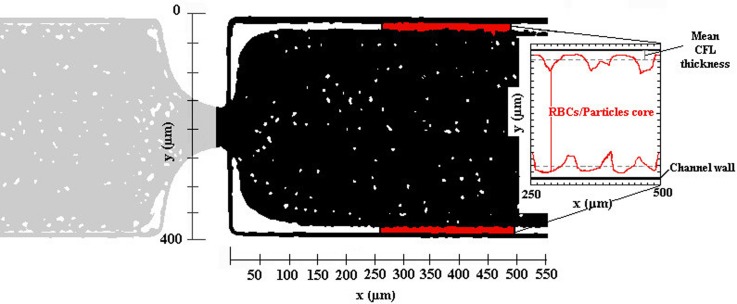
The recorded image sequences were evaluated using ImageJ software using the function “Z project”. The image analysis result is presented by a single image having a region brighter than the background, corresponding to the CFL region (Fig. 2). The intensity level distinction was used to identify the CFL thickness since the position of the RBCs and of PMMA microbead core in the microchannel is relatively clear. More details about this image analysis can be found in the study by Pinho et al.8
FIG. 2.
Example of the image analysis result and scheme of the CFL measurements performed downstream of the hyperbolic contraction, here for the working fluid containing PMMA microbeads.
Note that in the CFL thickness analyses, we have only measured downstream of the contraction since for all the fluids studied in this work, we have observed that the CFL thickness upstream is residual, as can be seen in Fig. 2.
E. Microchannels characterization
For the deformability analysis, a longer hyperbolic microchannel (MDI) having dimensions of 396 15 15 μm, for the width (, minimum contraction width , and depth, respectively, was used, cf. Table II. This high sensitivity microchannel is composed of a single hyperbolic contraction with a large Hencky strain of 3.3 followed by a sudden expansion. This large Hencky strain not only generates a linear increase in the velocity but also allows an accurate way to measure the deformation index (DI) of the cells and microbeads without tumbling or rotational motions that are promoted by shear.
TABLE II.
Microchannel dimensions and experimental parameters: Hencky strain (, aspect ratio and Reynolds number ().
| PDMS microchannel | (μm) | (μm) | L (μm) | εH | |||
|---|---|---|---|---|---|---|---|
 |
MDI | 396 | 15 | 780 | 3.3 | 0.038 | 0.22 ≤ Re ≤ 0.67 |
 |
M1 | 398 | 50 | 140 | 2 | 0.25 | 0.019 ≤ Re ≤ 3.47 |
| M10 | 398 | 50 | 1378 | 2 | 0.25 | ||
 |
MT | 400 | 20 | 380 | 3 | 0.25 | |
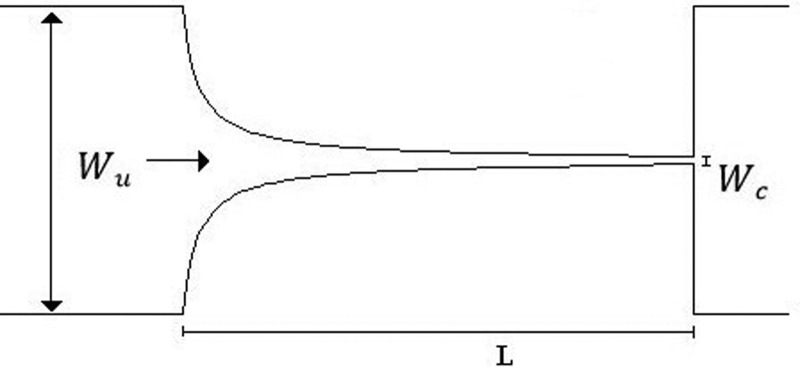
The CFL evaluation was performed downstream of contractions in different PDMS microchannels, designed to impose a large extensional flow deformation. In particular, one microchannel with a single hyperbolic-shaped contraction (M1) and a hyperbolic microchannel having a sequence of 10 (M10) hyperbolic-shaped contractions, as shown in Table II, were used. The evaluation is performed for the suspended healthy and glucose-rich RBCs and for the particulate viscoelastic fluids. The geometry of the hyperbolic contractions in the microchannels, M1 and M10, has the same dimensions with inlet and outlet widths of 398 μm (, a length of 140 μm ( and a minimum contraction width of 50 μm , corresponding to a Hencky strain of 2 (. The depth of all tested microchannels was 100 μm. Table II summarizes the microchannels used and several important parameters.
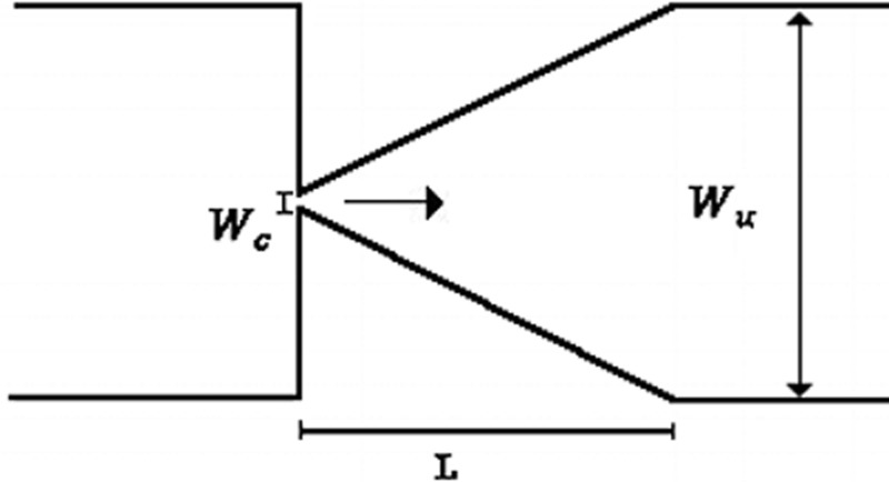
A microchannel with an abrupt contraction followed by a triangular expansion was also used, denoted as microchannel MT, to performed CFL measurements as it presents higher Hencky strain value than the tested hyperbolic geometries, while maintaining the same aspect ratio ().
Most of the blood microchannel flow studies in the literature pertain to shear flow conditions1–3,8,15 usually not taking into account the elastic nature of blood. However, in a more realistic approach to the microcirculation flow properties, the elastic behavior should also be considered as it is significantly enhanced at small scale flows. Thus, we have decided to perform flow experiments within hyperbolic-shaped contractions in which extensional elasticity properties are significantly enhanced in particular for geometries with Hencky strains higher than 2. In addition, increasing the number of consecutive hyperbolic contractions and abrupt expansions enhances fluid stretching and provides an efficient way to investigate the elastic properties of fluids with large extensional viscosities,36,49 as done in this work. Moreover, at these small dimensions, the elasticity of the fluid can be assessed while limiting inertial effects. The microchannel MT has an abrupt contraction followed by a smooth triangular expansion and also has a high Henchy strain of 3 promoting the CFL formation downstream of the contraction, and as Rodrigues et al.9 conclude in their study, has a strong impact on the CFL thickness.
The microchannel dimensions were also close to the dimensions of human microvessels and in particular the strong extensional deformations imposed by the sequence of contractions, and expansions may represent the effect of irregular networks that can be found in in vivo microcirculation. With these geometries and with the working flow rates, we were able to achieve Reynolds numbers () in the range of 0.01–3.5 and shear rates that can be found at in vivo blood flow in microvessels with dimensions from 80 μm up to 500 μm.50
III. RESULTS AND DISCUSSION
A. Deformation index and aggregation assessment
1. Deformability analysis
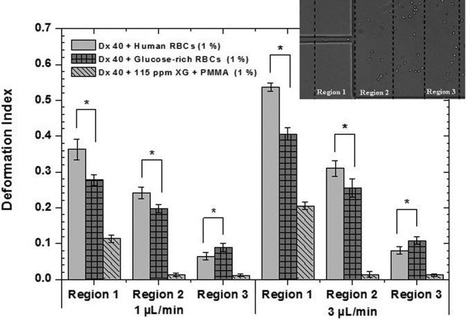
The main purpose of this work is to develop analogue fluids that mimic in vitro suspensions of pathological RBCs in terms of rheological and in vitro flow behavior. The pathological RBCs were obtained by incubation in a rich-glucose medium, with 100 mM of glucose, for twelve hours at 37 °C. To better analyse and quantify the damage caused in the RBC membranes by the high glucose concentration, deformability tests were performed with healthy and glucose-rich RBCs suspended in Dx 40, using the microchannel MDI. The DIs obtained for the pathological RBCs were compared with DIs of the healthy RBCs that were used as a control sample. In Fig. 3, it is possible to observe that the incubated RBCs present a smaller DI than the healthy RBCs for regions 1 and 2. For instance, in Region 1, the healthy RBCs present DIs of 0.36 and 0.54, for the flow rates of 1 and 3 μl/min, respectively, whereas the glucose-rich RBCs present DIs of 0.27 and 0.41. In contrast, in Region 3, the pathological RBCs are more deformed than the healthy cells. Taking into account these results, the same test was performed with the PMMA particles, 1% by weight, suspended in the viscoelastic fluid (Dx 40 + 115 ppm), in order to analyse also their ability to elongate when passing through the small contraction. Overall, the PMMA microbeads always have the smallest DIs regardless of the region; however, some small elongations in Region 1 followed by a fast recovery to their original shapes in the expansion region were observed. All deformability experiments were performed in the same microchannel, MDI, at a room temperature of 20 ± 2 °C.
FIG. 3.
Deformation index of healthy and glucose-rich RBCs suspended in Dx 40 at 1% (ν/ν) and PMMA microbeads also at 1% (w/w) suspended in the viscoelastic base fluid, flowing through the three selected regions of the hyperbolic microchannel MDI. The error bars represent the mean standard deviation at 95%, and * was considered to be statistically significant. All deformability tests were performed in microchannel MDI, at a room temperature of 20 ± 2 °C.
With this protocol, a similar in vitro condition to the stage of in vivo hyperglycaemia has been developed, as the deformability results obtained for Region 1 clearly show that the incubated RBCs have increased their rigidity. These results corroborate similar findings in the literature.25,27–29
In contrast, the results obtained for Region 3 show that glucose-rich RBCs have a larger DIs when compared with the healthy RBCs. This could be explained by the difficulty of the glucose-rich RBCs in recovering their original shape due to the reduction in their membrane viscoelastic properties.24,25 The PMMA microbeads also show some deformation; however, a quick recover is observed in Regions 2 and 3. Hence, by performing the deformability tests, we have demonstrated that the less deformable cells correspond to pathological in vitro RBCs. In addition, the PMMA microbeads have demonstrated some ability to deform in Region 1, and qualitatively, they were the best approximation to the behavior of rigid RBCs passing through the hyperbolic contraction. In this way, PMMA microbeads can be a reasonable option as the cellular component of the proposed analogue fluids. Note that the particles used in the literature for similar studies34,38,39,41 are rigid or semi-rigid and larger; this is an important issue regarding the development of two-phase analogue fluids because it is extremely difficult to develop deformable micron-sized particles in a considerable quantity to make blood analogue fluids. By using a flow focusing technique, Munoz-Sanchez et al.51 were able to produce a limited amount of PDMS microbeads with diameters below 10 μm and elasticity close to healthy RBCs. However, they still have to overcome several challenges such as the time of production, the microbead final concentration, and the process to dry the microbeads.
Therefore, and in spite of the shortcomings in the behavior of the PMMA microbeads, as in Region 3, we consider that they remain a good approximation to the representation of pathological RBCs, as their values in Region 1 demonstrate that they also present some ability to deform.
2. Aggregation assessment
It is known that diabetes and in particular the hyperglycaemia stages reduce the cell deformability, promote the aggregation of the erythrocytes, and as a consequence, increase the blood viscosity.28,52 In addition, in pathological microenvironments, the increment of the aggregation level and blood viscosity promote the increase in the CFL thickness due to cell interactions and the enhanced cell migration away from the microchannel wall.22,23,26,53 One of the main objectives of this study is to investigate in detail the CFL development for all the proposed analogue fluids, and bearing in mind that the incubation at a high glucose concentration tends to increase the RBC aggregation levels, we have also decided to observe under the microscope the level of aggregation for each sample.
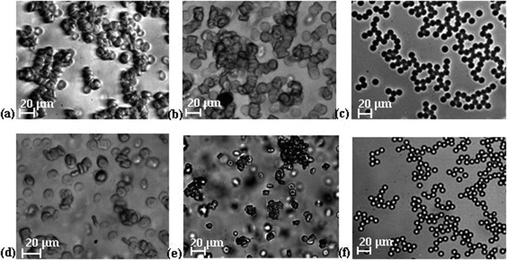
The healthy RBCs suspended in plasma may promote the development of microstructures called rouleaux with an organized structure similar to stacks of coins,4 although in pathological environments three-dimensional aggregates are more likely to occur.4,22 To investigate the level of aggregation, the same amount of healthy and glucose-rich cells and PMMA microbeads was suspended in plasma and the formation of small clusters for all the tested samples were observed. For the case of the healthy cells, the formation of simple rouleaux (one-dimensional) was clear, as shown in Fig. 4(a), whereas for glucose-rich RBCs, the presence of complex three-dimensional disorganized agglomerate structures was observed as shown in Fig. 4(b). For PMMA microbeads suspended in plasma, the formation of organized structures was clearly identified [Fig. 4(c)].
FIG. 4.
Microscopy images of human RBCs and microbeads suspended in plasma: (a) healthy RBCs, objective 20×; (b) glucose-rich RBCs, objective 20×; and (c) PMMA microbeads, objective 10×. Microscopy images of cells and microbead suspensions in Dx 40: (d) healthy RBCs, objective 20×; (e) glucose-rich RBCs, objective 10×; and (f) PMMA microbeads, objective 10×.
In in vitro blood flow experiments, Dx 40 is frequently used to prevent the sedimentation, clotting, and jamming of cells and also works as a non-aggregating medium, as is possible to observe in Fig. 4(d) where suspended healthy RBCs in Dx 40 show negligible rouleaux formation when compared with the healthy cells suspended in plasma [Fig. 4(a)]. However, when glucose-rich RBCs were suspended in Dx 40, this medium was less efficient as a non-aggregating medium. Figure 4(e) shows the presence of rather large aggregated structures, confirming previous findings of the formation of larger aggregates when high concentrations of glucose are involved.28,29 For the case of the PMMA microbeads, we have also observed the creation of organized structures within the Dx 40 medium. Overall, the performed aggregation assessment shows that the glucose-rich RBCs present more aggregation then the healthy RBCs suspended in the same medium and the PMMA microbeads present similar behavior in both media.
B. Rheological characterization of suspended RBCs and their analogues
1. Steady shear rheology of the suspended cells
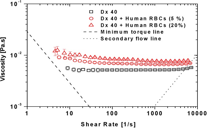
Figure 5 compares the viscosity curves for the suspension medium Dx 40 and human healthy RBCs suspended in Dx 40 with 5% and 20% of hematocrit. It is possible to observe that Dx 40 has a constant viscosity of 5.2 mPa.s; however, as will be shown later in Sec. III B 3, Dx 40 has some elasticity, so it behaves as a Boger-like fluid.54 By adding 5% and 20% of RBCs, a clear increment of the viscosities of both fluids is obvious in comparison to the pure Dx 40. At low shear rates, the curves for 5% and 20% hematocrit exhibit shear-thinning up to shear rates of the order of few hundred reciprocal seconds, after which the suspension tends to a constant viscosity (Newtonian behavior). This weak shear-thinning for the cells suspended fluids is mainly associated with the cell deformability and less so to the weak formation of rouleaux at low shear rates, as we have demonstrated in the aggregation studies. By increasing the shear rate, the structures tend to break down and the deformable cells align, and as a result, the viscosity decreases.
FIG. 5.
Viscosity curves for the Dx 40 and healthy human RBCs at 5% and 20% of Hct suspended in Dx 40. All the measurements were performed at 20 °C, and the error bars represent the mean standard deviation.
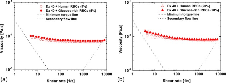
By increasing the RBC rigidity (glucose-rich RBCs), a slight increment in the viscosity values for the 5% of Hct with respect to the healthy RBCs can be noted, especially at low shear rates [Fig. 6(a)]. However, taking into account the standard deviation of the data, this variation is of no significance. The same effect is observed for 20% of Hct, as shown in Fig. 6(b).
FIG. 6.
Viscosity curves for the human healthy and glucose-rich RBCs with: (a) 5% of Hct and (b) 20% of Hct suspended in Dx 40. The error bars represent the mean standard deviation.
2. Steady shear rheology of the developed analogue fluids
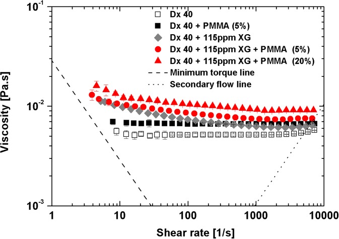
Figure 7 plots the shear rheology of fluids associated with the semi-rigid PMMA microbeads. The addition of 5% of PMMA microbeads to the continuous phase increases the viscosity of Dx 40, but the viscosity of the suspension remains constant. However, adding 115 ppm of xanthan gum to Dx 40 is sufficient to introduce shear-thinning (filled rhombus), and by further adding 5% or 20% (w/w) of PMMA microbeads (10 μm of diameter), there is a viscosity increase, accompanied by a small reduction of shear-thinning intensity as also shown in the data of Fig. 7, although some shear-thinning is still visible. Note that both base fluids exhibit elasticity, with the Dx 40 + 115 ppm XG being more elastic as will be shown below (subsection III B 3).
FIG. 7.
Viscosity curves for the blood analogue fluids. All the measurements were performed at 20 °C, and the error bars represent the mean standard deviation.
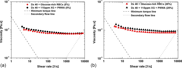
Figure 8 compares the viscosity of the suspended glucose-rich RBCs with those of the proposed particulate viscoelastic blood analogue. A reasonable agreement is observed, especially for the 5% suspension, but small differences can still be found at low shear rates. By increasing the concentration of microbeads to 20%, the difference between both curves [Fig. 8(b)] increases slightly possibly due to different abilities of the PMMA microbeads and glucose-rich RBCs to deform under flow (glucose-rich RBCs deform better than PMMA microbeads as shown in Fig. 3).
FIG. 8.
Viscosity curves for both pathological cell suspensions and developed particulate blood analogue: (a) 5% of glucose-rich RBCs and microbeads and (b) 20% of glucose-rich RBCs and microbeads. All the measurements were performed at 20 °C, and the error bars represent the mean standard deviation.
3. Oscillatory shear rheology
a. Small amplitude oscillatory shear
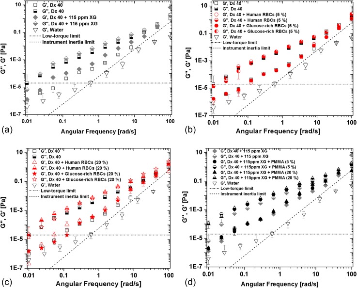
To perform a quantitative analysis of the relative magnitude of elastic and viscous behaviors of the developed analogues, measurements of the loss (G″) and storage moduli (G′) were carried out within the viscoelastic linear range, at an amplitude of 0.1 Pa. By analysing Fig. 9, it is possible to observe that the storage and loss moduli increase with frequency, with the variation being stronger for the elastic component (G′). All fluids are typically more viscous than elastic, with G″ being consistently higher than G′ up to a frequency between 10 and 100 rad/s, in which there seems to be a crossover of G′ versus ω for many of the plots. We can also conclude that the viscous and elastic influences come mostly from the continuous phase, Dx 40 and Dx 40 + 115 ppm of XG. As expected, the continuous phase of the developed analogue fluids is more elastic and more viscous than Dx 40, as seen in Fig. 9 (a).
FIG. 9.
Storage and loss moduli of all the working fluids developed in this work at 20 °C as a function of the angular frequency: (a) continuous phase, (b) suspensions of healthy and glucose-rich cells, at 5% concentration in Dx 40, (c) at 20% of concentration, and (d) developed analogue fluids at both microbead concentrations. The error bars represent the mean standard deviation. The low-torque limit line represents the limit of accuracy of the rheometer Bohlin CVO.
The instrument low-torque limit line ()55 and the line of instrument inertia (55 were added to Figs. 9 and 10 for a better understanding of the equipment limitations and validity of the measurements. The line of instrument inertia is a slope 2 dashed line, marking the onset of inertia effects, and the data for water plotted in Fig. 9 clearly show that the variation of its with is solely due to inertia, as expected for a Newtonian fluid. Clearly, the data for all working fluids (so, excluding water) all lie above the instrument inertia limit even if at high frequencies the difference is small. With regard to the low torque limit line (horizontal dotted-dashed line) only for the less elastic fluids, a limited number of data points lie below the limit (between 1 and 3 data points of 12 data points for each fluid), but this takes place only at low frequencies ( < 0.1 rad/s). Therefore, with the exception of these few points, the data sets in these figures are in a range of reliable measurements.
FIG. 10.
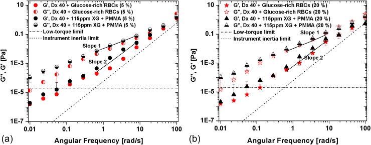
Storage (G′) and loss modulus (G″) for the suspension of glucose-rich RBCs in comparison to the correspondent analogue fluid at (a) 5% and (b) 20%. The error bars represent the mean standard deviation. The low-torque and inertia limit lines represent the limit of accuracy of the rheometer Bohlin CVO.
With regard to the suspensions of healthy and glucose-rich cells, at 5% concentration in Dx 40 [Fig. 9(b)], there are no significant differences, whereas for the 20% suspensions, we observe that G″ is higher for the glucose-rich RBCs than for the healthy cells [seen in Fig. 9(c)], as we have also observed in the steady shear data of Fig. 8(b). For the developed analogues, a larger increase in G″ is also observed [Fig. 9(d)].
Hence, these results indicate that all the working fluids while being essentially viscous present a non-negligible elastic contribution. Since a major objective is the development of analogue fluids of pathologic cell suspensions, Fig. 10 composes the corresponding SAOS data comparing the rheological behavior of the analogue fluids and of the glucose-rich RBCs. In Fig. 10, the lines of slopes 1 and 2 were added for a better clarification of the increasing ratios of G′ and G″, and the instrument low-torque limit line and the G′ of water have also been added.
We clearly observe in Fig. 10 that the analogue fluids are always more elastic and more viscous than the suspensions of glucose-rich RBCs; however, taking into account the error bars, the differences are not very significant. In addition, at least in the linear viscoelastic region, G′ and G″ of the analogue fluids represent very well the corresponding properties of the pathological suspensions.
b. Large amplitude oscillatory shear
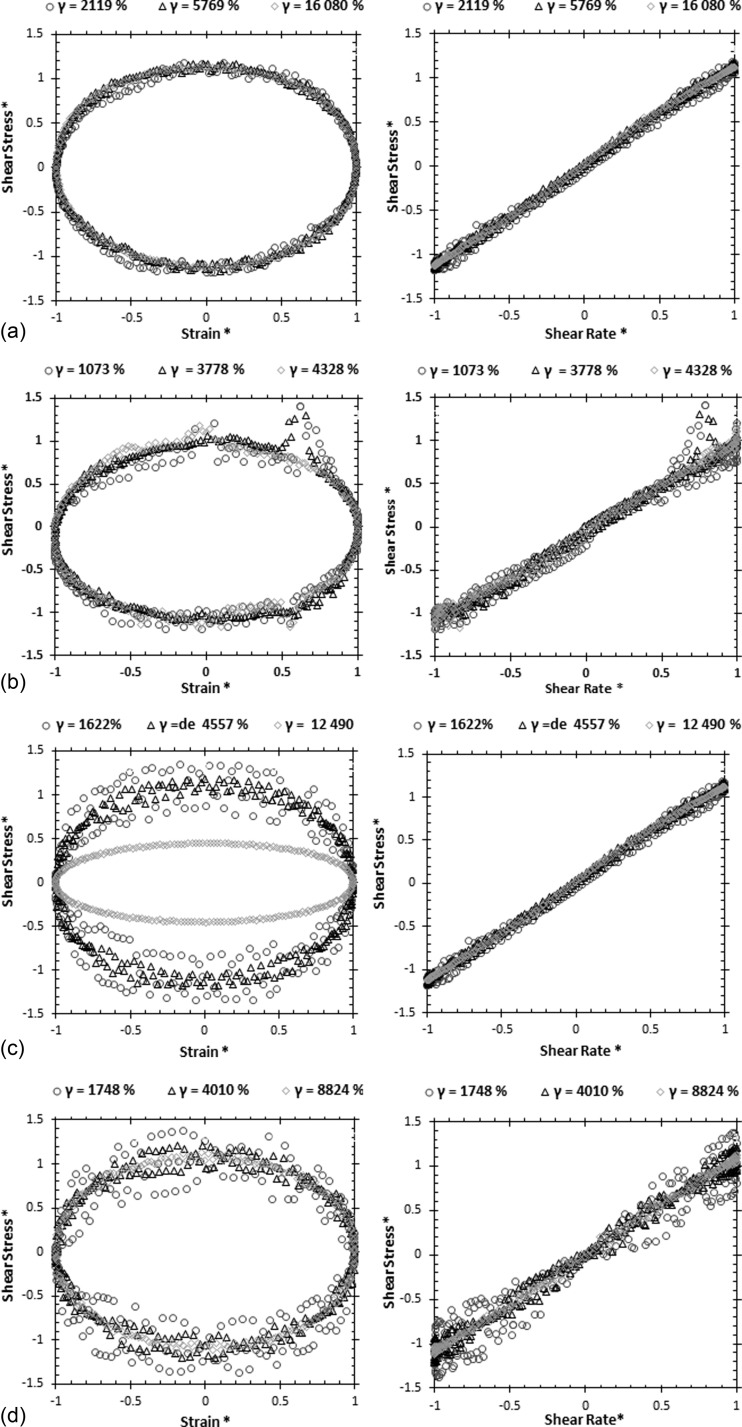
Large amplitude oscillatory shear (LAOS) tests were performed varying the amplitude of the imposed shear stress at two angular frequencies of 0.1 and 1 rad/s. Three different maximum deformations were selected corresponding to three different shear stresses of 0.02, 0.06, and 0.14 Pa, for the lower angular frequency (ω = 0.1 rad/s), and 0.16, 0.40 and 1 Pa for ω = 1 rad/s. Fig. 11 plots the Lissajous-Bowditch curves normalized with the first harmonic. The LAOS tests allow a complete characterization of the fluids, but only the analogue fluids could be measured since ethical issues prevent the use of blood in the rheometer equipped with this test.
FIG. 11.
Normalized Lissajous-Bowditch plots of shear stress as a function of strain and shear rates at two angular frequencies for the developed blood analogues: PMMA microbeads suspended in Dx 40 + 115 ppm XG at (a) 5% of PMMA, ω = 0.1 rad/s; (b) 20% of PMMA, ω = 0.1 rad/s; (c) 5% of PMMA, ω = 1 rad/s; and (d) 20% of PMMA, ω = 1 rad/s.
At the lower angular frequency of 0.1 rad/s, all data plotted in Figs. 11(a) and 11(b) collapse onto single curve behavior in the normalized Lissajous-Bowditch plots, indicating an essentially viscous behavior, since the area enclosed by the curves in the shear stress versus shear rate plot is very small (plot on right hand-side).
The behavior starts to change at the higher angular frequency of 1 rad/s, as is clear from the inspection of Figs. 11(c) and 11(d). Here, while the behavior at large deformation exhibits the same pattern seen at lower frequency, at the two lowest deformations, data are more disperse and the enclosed area on the stress-rate of strain plot suggest some elasticity, albeit small.
From these results and by using the framework MTIlaos described by Ewoldt et al.,44 we have also quantified some other quantities listed in Table III. The minimum strain elastic modulus, G′M, is represented by the tangent modulus at zero strain, and the maximum strain elastic modulus, G′L, is represented by the secant modulus at the maximum strain. To represent the viscous nature of the viscoelastic analogue fluids, the minimum-rate and large-rate dynamic viscosities η′M and η′L were also quantified. The strain-stiffening and shear-thickening ratio, S and T, respectively, were also measured using the same framework that requires raw stress and strain data.
TABLE III.
Minimum (G′M) and large (G′L) elastic moduli, minimum (η′M) and large–rate (η′L) dynamic viscosities, and the strain-stiffening (S) and shear-thickening ratio (T) at two angular frequencies. Data obtained following the MITlaos procedure of Ewoldt et al.44 for the developed analogue fluids and PMMA microbeads at 5% and 20% concentrations suspended in the viscoelastic base fluid are given.
| ω (rad/s) | Blood analogue (%) | Strain (%) | G′M (Pa) | G′L (Pa) | η′M (Pa s) | η′L (Pa s) | S | T |
|---|---|---|---|---|---|---|---|---|
| 0.1 | 5 | 16080 | 1.27 × 10⁻⁶ | 8.77 × 10⁻⁶ | 1.21 × 10⁻² | 1.09 × 10⁻² | −0.44 | −0.10 |
| 20 | 4328 | 1.15 × 10⁻⁴ | 1.08 × 10⁻⁴ | 3.18 × 10⁻² | 2.97 × 10⁻² | −0.06 | −0.07 | |
| 1 | 5 | 12490 | 1.62 × 10⁻⁴ | 1.10 × 10⁻⁴ | 9.72 × 10⁻³ | 8.97 × 10⁻³ | −0.47 | −0.08 |
| 20 | 8824 | 2.26 × 10⁻⁴ | 1.74 × 10⁻⁵ | 1.33 × 10⁻² | 1.24 × 10⁻² | −11.97 | −0.07 |
These results, for all analogue fluids, indicate a negative shear-thickening ratio, T < 0, characterizing a shear-thinning behavior during the oscillation cycle. Also, η′M > η′L corresponds again to an intra-cycle shear-thinning behavior, corroborating the data obtained with the steady shear tests. Regarding the elastic variables, it is possible to observe an intra-cycle strain-softening (S < 0) behavior since G′M > G′L even though both are very small, confirming the essentially viscous nature of the analogue fluids and of their continuous phase. These findings are in agreement with the intra-cycle behavior observed in Fig. 10, by the normalized Lissajous-Bowditch plots of the stress versus strain and stress versus shear rate.
C. Cell-free layer assessment
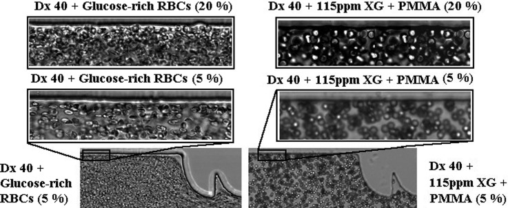
In this study, we have performed flow visualizations and measurements of the CFL thickness for the suspended healthy and glucose-rich RBCs flowing in the three different PDMS microchannels (M1, M10, and MT) (cf. Table II). Note that, for all the fluids studied, we have observed that the CFL thickness upstream of the contractions is residual (Fig. 12), so we have only measured the CFL thickness downstream of the contractions. Figure 12 shows flows of 5% and 20% of glucose-rich RBCs suspended in Dx 40 and of PMMA microbeads suspended in the viscoelastic fluid, upstream the sequence of contractions of the microchannel M10. In Fig. 12, it is possible to observe that the CFLs are residual or inexistent.
FIG. 12.
Flow visualizations upstream the contraction sequence of the microchannel M10 for glucose-rich RBCs in Dx 40 and suspensions of PMMA microbeads in a viscoelastic medium, both at 5% and 20%. The objective is 20×.
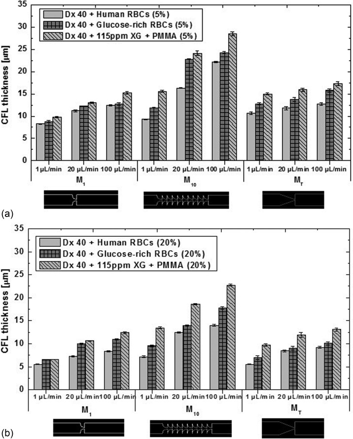
In addition, comparisons with the CFL formed by the flow of the particulate blood analogues were also performed, and the results are presented in Fig. 13. For all tested fluids, it has been observed that downstream of the contractions of the microchannels, there is a high propensity for CFL formation. The results show that the CFL thickness is influenced by the flow rate, the number of sequential hyperbolic elements and hematocrit; increment with the hyperbolic elements and flow rate, and decrease with the hematocrit [see Figs. 13(a) and 13(b)] for all the fluids. These results corroborate qualitatively the blood flow studies performed by other authors.8,9,12,22 The CFL thickness for the simple geometries M1 and MT and for 20% of healthy RBCs (closer to in vivo microcirculation environments) is also in good agreement with the in vivo results of Kim et al.6 and Yamaguchi et al.12
FIG. 13.
CFL thickness for the three suspensions: healthy and glucose-rich RBCs and the corresponding proposed analogue for 5% (a) and for 20% (b) of hematocrit. All the measurements were performed at 20 °C, and the error bars represent the mean standard deviation.
Since the analogue suspensions based on the Boger-like fluid continuous phase (Dx40 + PMMA microbeads) showed CFL thicknesses close to zero, i.e., very far from the behavior of healthy or pathological RBCs, and its rheological properties are also quite different from those suspension of cells, we have decided not to present the data of this fluid. In summary, Dx 40 + PMMA microbeads are a poor blood analogue, representing the suspensions of RBCs, healthy or pathological.
For the blood sample containing glucose-rich RBCs, the CFL thickness is always larger than for the healthy human RBCs for all the tested microchannels. Hence, these latter results reinforce the idea that the incubation applied to the healthy RBCs has indeed introduced changes to the structure and hemodynamic behavior of RBCs. One possible explanation for the observed CFL increase of the samples containing glucose-rich RBCs might be due to their tendency to form agglomerates, as already shown in Fig. 4. In the microcirculation, the aggregation of cells and their interactions are important factors that influence the hemodynamic and hemorheological behavior of blood. For instance, several authors have demonstrated that an increase in the RBCs aggregation, normally found at pathological conditions, promotes a significant increase in the CFL thickness,22,23,26 due to a more prominent migration of RBCs and their aggregates, further increasing the cell aggregation level.6 This tendency to form larger agglomerates increases also the sedimentation especially within the syringe reservoir and supply tubes, whereas the sedimentation in the microchannels themselves is negligible considering the flow transit time, except for the lowest flow rate. This is so because the syringe volume allows for a long experiment in which the sedimentation occurs, while the fluid awaits its entrance into the microchannel, especially for agglomerates, contributing to the decrease in the glucose-rich RBCs concentration and consequently a more intense cell migration away from the wall, resulting in a thicker CFL. The sedimentation time of the RBC agglomerates and the transit times are estimated in the supplementary material.
During the flow experiments with the developed viscoelastic particulate analogues, a migration of the particles towards the centreline and the formation of a CFL thicker than for the glucose-rich RBCs were observed. This increment of the CFL thickness could be due to the shear-thinning behavior56–59 of the suspending fluid and sedimentation effect that is higher for the PMMA microbeads, inducing a further increment in the CFL thickness. The sedimentation of the PMMA particles along the inlet tubes and especially in the syringe is higher than that of the glucose-rich RBCs since they present a higher sedimentation ratio, as shown in the supplementary material [Figs. 16(c) and 16(d)]. Also, analysing their transit times inside of the microchannels, for all the flow rates, we can conclude that individual PMMA particles or RBCs do not show significant sedimentation. Nevertheless, a significant reduction of the sedimentation time is obtained when agglomerates are formed, which are lower than the transit time of the flow within the microchannels for some low flow rates, as discussed in the supplementary material. These effects are bound to have an influence on the CFL measurements by increasing their thickness and consequently the difference between analogue fluids and glucose-rich RBCs.
The shear-thinning behavior, as observed by Li et al.,56 also promotes the motion of semi-rigid microbeads away from the walls under high inertia or elasticity forces since the analogue fluids were shown to be slightly more elastic and viscous than the suspension of glucose-rich RBCs as seen in the rheological data, and this supports a higher migration of the PMMA microbeads to the centreline than for the glucose-rich RBCs. This non-Newtonian effect combined with the elastic response associated with the extensional flow of the hyperbolic contractions enhances the migration of particles towards the low shear rate region, i.e., to the centre plane of the microchannel. This phenomenon is consistent with other experiments by Karimi et al.,58 Calejo et al.,41 and Loon et al.60 who found that the migration of spherical and semi-rigid particles depends strongly on the elasticity of the carrier fluid, and the migration towards the centreline tends to occur when smooth shear-thinning base fluids are used,41,57–59 as the viscoelastic base fluid used in this work suspended the PMMA microbeads.
In addition, the numerical study by Li et al.56 has demonstrated that the elastic effects drive the particles towards the channel centreline. They also showed that when the elastic and inertial forces are equilibrated in the flow, the particle migration tends to an equilibrium position in the microchannel. In this study, these elastic effects were stronger in the microchannel M10 due to the sequence of contractions that will allow us to achieve a more evident elastic response of the fluid. As we can see in Figs. 13(a) and 13(b), the microchannel M10 exhibited larger differences in the CFL thickness between the glucose-rich RBC suspensions and analogue fluids due to a stronger migration of the microbeads to the middle axis. It is also clear that we have observed a migration of particles to the middle axis of the microchannel, and a good agreement between the results was obtained in the microchannels M1 and MT.
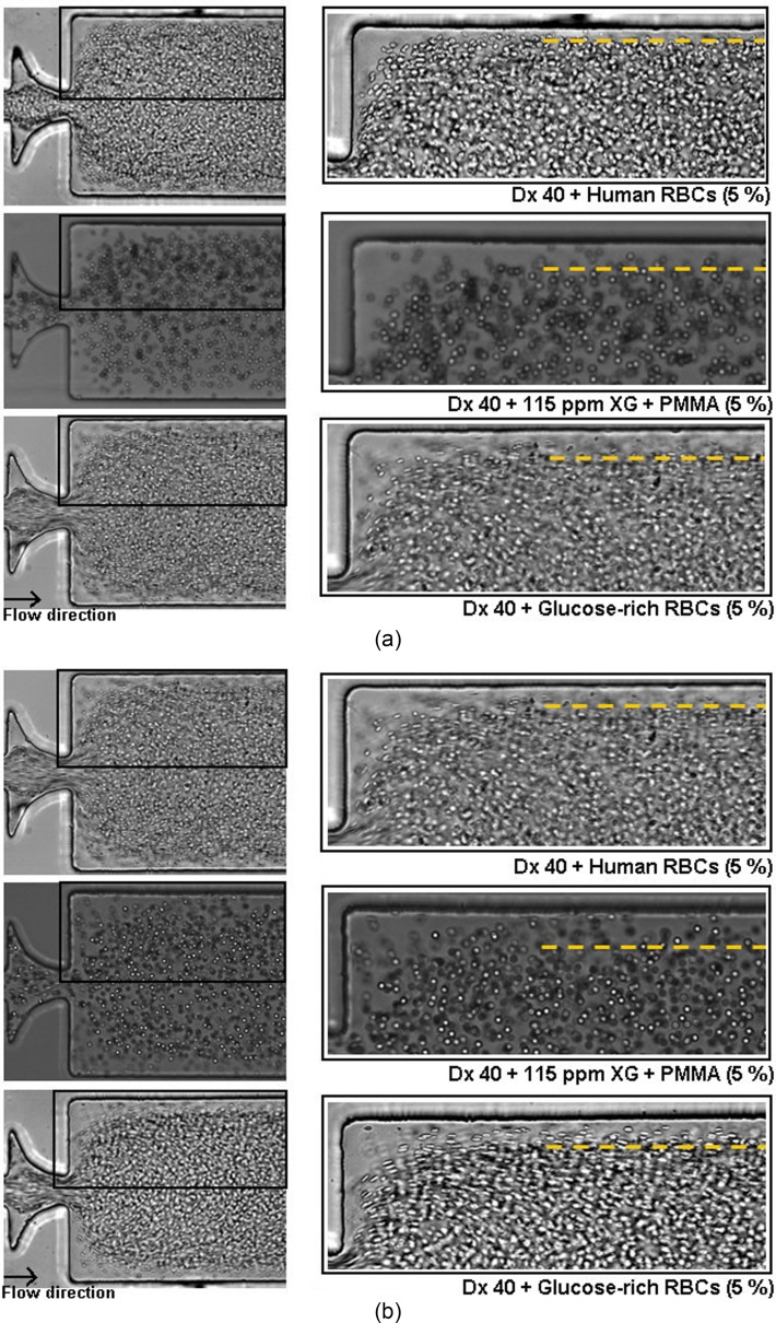
For instance, by increasing the flow rate up to 100 μl/min and consequently to a Reynolds value larger than 1, we have also obtained a higher shear rate and shear stress, leading to stronger elastic effects, and at these conditions, we have indeed observed higher migration of the RBCs and PMMA microbeads towards the region of lower shear rate, i.e., toward the centreline of the microchannel, where the fluid does not feel the shear-tinning effect and the viscous forces overcome the elastic forces, resulting in a ticker CFL for the three microchannels at this flow rate. In Fig. 14, we can observe the evolution of the CFL thickness for the 5% of suspensions in all continuous phases at flow rates of 20 μl/min [see Fig. 14(a)] and 100 μl/min [see Fig. 14(b)].
FIG. 14.
Flow visualizations downstream of the sudden expansion of the microchannel M10 at flow rates of (a) 20 μl/min and (b) 100 μl/min, for 5% of healthy and glucose-rich RBCs (Re ∼2.63) and PMMA microbeads suspended in the viscoelastic medium (Re ∼2.35).
Although there is a CFL difference between the analogue fluids and the suspensions of glucose-rich RBCs, even larger differences were found between the analogue fluids and the healthy RBC suspension. So, we believe that at the current stage, the proposed fluid is a reliable analogue fluid able to mimic the in vitro CFL phenomenon formed downstream of the contractions by the glucose-rich RBCs. In particular, for the microchannel M1, similar results were obtained between the analogue fluids and the suspensions of glucose-rich RBCs.
IV. CONCLUSIONS
The complexity and difficulties of working with blood in in vitro conditions, in particular with pathological blood samples, call for the development of blood analogue fluids that are able to mimic microcirculation phenomena, such as CFL, cell aggregation, and cell interactions in order to improve our understanding of blood cell dynamics in the microcirculation for healthy and pathological conditions. In this study, in vitro two-phase viscoelastic fluids were developed which are able to mimic the rheological and flow behavior of pathological RBCs suspended in dextran 40 (Dx 40) at room temperature. The analogue fluids were based on Dx 40 and relied on suspended semi-rigid PMMA microbeads, exhibiting viscoelastic behavior due to the addition of a small quantity of xanthan gum.
The pathological RBCs were obtained by an incubation of healthy RBCs in high concentration of glucose, representing the pathological stage of hyperglycaemia in diabetic complications, and an analysis of their deformation index (DI) was performed, showing that the glucose-rich RBCs have a smaller DI than the healthy RBCs. Similar deformability tests were performed with PMMA microbeads, showing that they present some ability to deform when flowing through the hyperbolic contraction, so we used these semi-rigid microbeads to represent the cellular component of the proposed analogue fluids.
Viscosity curves and small amplitude oscillatory shear tests were performed for the suspension of healthy and glucose-rich RBCs and also for the developed analogue fluids. A good agreement between the viscosity curves and the linear viscoelastic moduli (G′ and G″) was obtained for the suspension of pathological RBCs and the corresponding analogue fluids. Overall, the rheological tests showed that the working fluids used here have a viscous component that prevails over the elastic behavior, but nevertheless a non-negligible elastic character is exhibited at 20 °C. Large oscillatory shear tests were also performed to obtain a more extended characterization of the analogue fluids, and the results corroborated the shear-thinning behavior.
Additionally, the ability of the developed particulate viscoelastic fluids to present a similar flow behavior in comparison to the glucose-rich RBCs flowing within microfluidic devices was analysed, in particular the cell-free layer (CFL) thickness downstream of a contraction. The glucose-rich RBCs presented a thicker CFL than the suspensions of healthy RBCs. It is likely that this CFL increment is in part associated with the presence of some agglomerates, sedimentation effects, and changes in their shape and internal viscosity. Regarding the CFL formed by the analogue fluid, suspensions of PMMA microbeads at concentrations of 5 and 20%, we have observed that their CFL thickness resembles closely that of the fluid containing pathological RBCs suspended in Dx 40.
In contrast to the majority of the existing blood analogues, this is the first analogue fluid able to approximate not only the flow behavior of glucose-rich RBCs in microchannels but also the rheological properties of the suspensions of RBCs. Therefore, it can be concluded from this work that the developed analogue is a promising fluid to perform in vitro blood studies and consequently to improve our understanding regarding the flow behavior of pathological blood cells in the microcirculation and for this particular case to mimic the pathological stage of hyperglycemia in diabetes.
V. SUPPLEMENTARY MATERIAL
See supplementary material for detail information about the rheological measurements performed with the stress-controlled rheometer Bohlin CVO with the gap size of 30 μm and about the sedimentation effect observed during the flow visualizations.
ACKNOWLEDGMENTS
The authors acknowledge the financial support provided by Fundação para a Ciência e a Tecnologia (FCT), COMPETE, and FEDER through the Ph.D. scholarship SFRH/BD/89077/2012, Grant IF/00148/2013, and project POCI-01–0145-FEDER-016861 (with associated reference PTDC/QEQ-FTT/4287/2014) funded by COMPETE2020—Programa Operacional Competitividade e Internacionalização (POCI) with the financial support of FCT/MTES through national funds (PIDDAC) and by the project Nos. PTDC/EQU-FTT/118716/2010, EXPL/EMS-SIS/2215/2013, UID/EMS/00532/2013, and UID/EMS/04077/2013.
References
- 1. Lima R., Ishikawa T., Imai Y., Takeda M., Wada S., and Yamaguchi T., J. Biomech. 41(10), 2188–2196 (2008). 10.1016/j.jbiomech.2008.04.033 [DOI] [PubMed] [Google Scholar]
- 2. Lima R., Ishikawa T., Imai Y., Takeda M., Wada S., and Yamaguchi T., Ann. Biomed. Eng. 37(8), 1546–1559 (2009). 10.1007/s10439-009-9732-z [DOI] [PubMed] [Google Scholar]
- 3. Lima R., Ishikawa T., Imai Y., and Yamaguchi T., in In Single and Two-Phase Flows on Chemical and Biomedical Engineering, edited by Dias R., Martins A. A., Lima R., and Mata T. M. ( Bentham Science, 2012), pp. 513–547. [Google Scholar]
- 4. McHedlishvili G. and Maeda N., Jpn. J. Physiol. 51(1), 19–30 (2001). 10.2170/jjphysiol.51.19 [DOI] [PubMed] [Google Scholar]
- 5. Kim S., Kong R. L., Popel A. S., Intaglietta M., and Johnson P. C., Microcirculation 13(3), 199–207 (2006). 10.1080/10739680600556878 [DOI] [PubMed] [Google Scholar]
- 6. Kim S., Ong P. K., Yalcin O., Intaglietta M., and Johnson P. C., Biorheology 46(3), 181–189 (2009). 10.3233/BIR-2009-0530 [DOI] [PubMed] [Google Scholar]
- 7. Faivre M., Abkarian M., Bickraj K., and Stone H. A., Biorheology 43(2), 147–159 (2006). [PubMed] [Google Scholar]
- 8. Pinho D., Yaginuma T., and Lima R., BioChip J. 7(4), 367–374 (2013). 10.1007/s13206-013-7408-0 [DOI] [Google Scholar]
- 9. Rodrigues R. O., Lopes R., Pinho D., Pereira A. I., Garcia V., Gassmann S., Sousa P. C., and Lima R., BioChip J. 10(1), 9–15 (2016). 10.1007/s13206-016-0102-2 [DOI] [Google Scholar]
- 10. Robin F. and Torsten L., The viscosity of the blood in narrow capillary tubes (American Physiological Society), Vol. 96, pp. 562–568.
- 11. Nobuji M., Yoji S., Junya T., and Norihiko T., Erythrocyte flow and elasticity of microvessels evaluated by marginal cell-free layer and flow resistance (American Journal of Physiology – Heart and Circulatory Physiology, 1996), Vol. 271, pp. H2454–H2461. [DOI] [PubMed]
- 12. Yamaguchi S., Yamakawa T., and Niimi H., Biorheology 29(2–3), 251–260 (1991). [DOI] [PubMed] [Google Scholar]
- 13. Vennemann P., Kiger K. T., Lindken R., Groenendijk B. C., Stekelenburg-de Vos S., ten Hagen T. L., Ursem N. T., Poelmann R. E., Westerweel J., and Hierck B. P., J. Biomech. 39(7), 1191–1200 (2006). 10.1016/j.jbiomech.2005.03.015 [DOI] [PubMed] [Google Scholar]
- 14. Cho S., Ye S. S., Leo H. L., and Kim S., in Visualization and Simulation of Complex Flows in Biomedical Engineering ( Springer, 2014), pp. 89–100. [Google Scholar]
- 15. Pinho D., Rodrigues R. O., Faustino V., Yaginuma T., Exposto J., and Lima R., J. Biomech. 49(11), 2293–2298 (2016). 10.1016/j.jbiomech.2015.11.037 [DOI] [PubMed] [Google Scholar]
- 16. Siddhartha T., Kumar Y. V. B. V., Amit P., Suhas S. J., and Amit A., J. Micromech. Microeng. 25(8), 083001 (2015). 10.1088/0960-1317/25/8/083001 [DOI] [Google Scholar]
- 17. Yaginuma T., Oliveira M., Lima R., Ishikawa T., and Yamaguchi T., Biomicrofluidics 7(5), 054110 (2013). 10.1063/1.4820414 [DOI] [PMC free article] [PubMed] [Google Scholar]
- 18. Rodrigues R. O., Bañobre-López M., Gallo J., Tavares P. B., Silva A. M. T., Lima R., and Gomes H. T., J. Nanoparticle Res. 18(7), 194 (2016). 10.1007/s11051-016-3498-7 [DOI] [Google Scholar]
- 19. Rodrigues R. O., Pinho D., Faustino V., and Lima R., Biomed. Microdevices 17(6), 108 (2015). 10.1007/s10544-015-0014-2 [DOI] [PubMed] [Google Scholar]
- 20. Fedosov D. A. and Gompper G., Soft Matter 10(17), 2961–2970 (2014). 10.1039/C3SM52860J [DOI] [PubMed] [Google Scholar]
- 21. Fedosov D. A., Fornleitner J., and Gompper G., Phys. Rev. Lett. 108(2), 028104 (2012). 10.1103/PhysRevLett.108.028104 [DOI] [PubMed] [Google Scholar]
- 22. Ong P. K., Jain S., Namgung B., Woo Y. I., and Kim S., Microcirculation 18(7), 541–551 (2011). 10.1111/j.1549-8719.2011.00114.x [DOI] [PubMed] [Google Scholar]
- 23. Zhang J., Johnson P. C., and Popel A. S., Microvasc. Res. 77(3), 265–272 (2009). 10.1016/j.mvr.2009.01.010 [DOI] [PMC free article] [PubMed] [Google Scholar]
- 24. Babu N. and Singh M., Clinical Hemorheology Microcirculation 31, 273–280 (2004). [PubMed] [Google Scholar]
- 25. Viskupicova J., Blaskovic D., Galiniak S., Soszyński M., Bartosz G., Horakova L., and Sadowska-Bartosz I., Redox Biol. 5, 381–387 (2015). 10.1016/j.redox.2015.06.011 [DOI] [PMC free article] [PubMed] [Google Scholar]
- 26. Ong P. K. and Kim S., Microcirculation 20(5), 440–453 (2013). 10.1111/micc.12045 [DOI] [PubMed] [Google Scholar]
- 27. Sehyun S., Yun-Hee K., Jian-Xun H., Yu-Kyung K., Jang-Soo S., and Megha S., Clinical Hemorheology Microcirculation 36, 253–261 (2007). [PubMed] [Google Scholar]
- 28. Shin S., Ku Y.-H., Suh J.-S., and Singh M., Clin. Hemorheol. Microcirc. 38(3), 153–161 (2008). [PubMed] [Google Scholar]
- 29. Riquelme B., Foresto P., D'Arrigo M., Valverde J., and Rasia R., J. Biochem. Biophys. Methods 62(2), 131–141 (2005). 10.1016/j.jbbm.2004.10.004 [DOI] [PubMed] [Google Scholar]
- 30. Deplano V., Knapp Y., Bailly L., and Bertrand E., J. Biomech. 47(6), 1262–1269 (2014). 10.1016/j.jbiomech.2014.02.026 [DOI] [PubMed] [Google Scholar]
- 31. Anastasiou A. D., Spyrogianni A. S., Koskinas K. C., Giannoglou G. D., and Paras S. V., Med. Eng. Phys. 34(2), 211–218 (2012). 10.1016/j.medengphy.2011.07.012 [DOI] [PubMed] [Google Scholar]
- 32. Gijsen F. J. H., van de Vosse F. N., and Janssen J. D., J. Biomech. 32(6), 601–608 (1999). 10.1016/S0021-9290(99)00015-9 [DOI] [PubMed] [Google Scholar]
- 33. Gray J. D., Owen I., and Escudier M. P., Exp. Fluids 43(4), 535–546 (2007). 10.1007/s00348-007-0317-z [DOI] [Google Scholar]
- 34. Nguyen T. T., Biadillah Y., Mongrain R., Brunette J., Tardif J. C., and Bertrand O. F., J. Biomech. Eng. 126(4), 529–535 (2004). 10.1115/1.1785812 [DOI] [PubMed] [Google Scholar]
- 35. Vlastos G., Lerche D., and Koch B., Biorheology 34, 19–36 (1997). 10.1016/S0006-355X(97)00002-4 [DOI] [PubMed] [Google Scholar]
- 36. Sousa P. C., Pinho F. T., Oliveira M. S. N., and Alves M. A., Biomicrofluidics 5(1), 014108 (2011). 10.1063/1.3567888 [DOI] [PMC free article] [PubMed] [Google Scholar]
- 37. Campo-Deaño L., Dullens R. P. A., Aarts D. G. A. L., Pinho F. T., and Oliveira M. S. N., Biomicrofluidics 7(3), 034102 (2013). 10.1063/1.4804649 [DOI] [PMC free article] [PubMed] [Google Scholar]
- 38. Maruyama O., Yamane T., Tsunemoto N., Nishida M., Tsutsui T., and Jikuya T., Artif. Organs 23(3), 274–279 (1999). 10.1046/j.1525-1594.1999.06316.x [DOI] [PubMed] [Google Scholar]
- 39. Maruyama O., Yamane T., Nishida M., Aouidef A., Tsutsui T., Jikuya T., and Masuzawa T., ASAIO J. 48(4), 365–373 (2002). 10.1097/00002480-200207000-00007 [DOI] [PubMed] [Google Scholar]
- 40. Nguyen T. T., Mongrain R., Prakash S., and Tardif J. C., paper presented at the Canadian Design Engineering Network Conference, Montreal, QC, Canada (2004). [Google Scholar]
- 41. Calejo J., Pinho D., Galindo-Rosales F., Lima R., and Campo-Deaño L., Micromachines 7(1), 4 (2016). 10.3390/mi7010004 [DOI] [PMC free article] [PubMed] [Google Scholar]
- 42. Mezger T. G., The Rheology Handbook: For Users of Rotational and Oscillatory Rheometers ( Vincentz Network GmbH & Co KG, 2006). [Google Scholar]
- 43. Schramm G., A Practical Approach to Rheology and Rheometry. ( Gebrueder HAAKE GmbH, Karlsruhe, 2006). [Google Scholar]
- 44. Ewoldt R. H., Winter P., and McKinley G. H., MITlaos version 2.1 Beta for MATLAB ( Cambridge, MA, 2007).
- 45. Ewoldt R. H., Hosoi A., and McKinley G. H., J. Rheol. 52(6), 1427–1458 (2008). 10.1122/1.2970095 [DOI] [Google Scholar]
- 46. Läuger J. and Stettin H., Rheol. Acta 49(9), 909–930 (2010). 10.1007/s00397-010-0450-0 [DOI] [Google Scholar]
- 47. Sousa P., Carneiro J., Vaz R., Cerejo A., Pinho F. T., Alves M., and Oliveira M., Biorheology 50, 269–282 (2013). [DOI] [PubMed] [Google Scholar]
- 48. Abramoff M. D., Magalhães P. J., and Ram S. J., Biophotonics Int. 11, 36–42 (2004). [Google Scholar]
- 49. Sousa P. C., Pinho F. T., Oliveira M. S. N., and Alves M. A., J. Non-Newtonian Fluid Mech. 165(11-12), 652–671 (2010). 10.1016/j.jnnfm.2010.03.005 [DOI] [Google Scholar]
- 50. Waite L. and Fine J. M., Applied Biofluid Mechanics ( McGraw-Hill Education, 2007). [Google Scholar]
- 51. Munoz-Sanchez B. N., Silva S. F., Pinho D., Vega E. J., and Lima R., Biomicrofluidics 10(1), 014122 (2016). 10.1063/1.4943007 [DOI] [PMC free article] [PubMed] [Google Scholar]
- 52. Tsukada K., Sekizuka E., Oshio C., and Minamitani H., Microvasc. Res. 61(3), 231–239 (2001). 10.1006/mvre.2001.2307 [DOI] [PubMed] [Google Scholar]
- 53. Namgung B., Sakai H., and Kim S., Clin. Hemorheol. Microcirc. 61(3), 445–457 (2015). 10.3233/CH-141909 [DOI] [PubMed] [Google Scholar]
- 54. Campo-Deaño L., Galindo-Rosales F. J., Pinho F. T., Alves M. A., and Oliveira M. S. N., J. Non-Newtonian Fluid Mech. 166(21–22), 1286–1296 (2011). 10.1016/j.jnnfm.2011.08.006 [DOI] [Google Scholar]
- 55. Ewoldt R. H., Johnston M. T., and Caretta L. M., in Complex Fluids in Biological Systems: Experiment, Theory, and Computation, edited by Spagnolie S. E. ( Springer New York, New York, NY, 2015), pp. 207–241. [Google Scholar]
- 56. Li G., McKinley G. H., and Ardekani A. M., J. Fluid Mech. 785, 486–505 (2015). 10.1017/jfm.2015.619 [DOI] [Google Scholar]
- 57. Chhabra R. P., Bubbes, Drops and Particles in Non-Newtonian Fluids, 2nd ed. ( CRC Press, 2006). [Google Scholar]
- 58. Karimi A., Yazdi S., and Ardekani A. M., Biomicrofluidics 7(2), 021501 (2013). 10.1063/1.4799787 [DOI] [PMC free article] [PubMed] [Google Scholar]
- 59. Tehrani M. A., J. Rheol. 40(6), 1057–1077 (1996). 10.1122/1.550773 [DOI] [Google Scholar]
- 60. Loon S. V., Fransaer J., Clasen C., and Vermant J., J. Rheol. 58(1), 237–254 (2014). 10.1122/1.4853455 [DOI] [Google Scholar]
Associated Data
This section collects any data citations, data availability statements, or supplementary materials included in this article.
Supplementary Materials
See supplementary material for detail information about the rheological measurements performed with the stress-controlled rheometer Bohlin CVO with the gap size of 30 μm and about the sedimentation effect observed during the flow visualizations.


