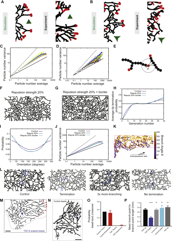
Figure S5.
Density Fluctuations and Ordering in Branching and Annihilating Random Walks, Related to Figures 4 and 5
(A and B) Comparison between representative experimental tip configuration at the edge of the invasion front and numerical simulation reveals large tip density fluctuations due to stochastic random exploration of space (arrowhead, [A], zoom from Figure 3C) or stochastic massive tip termination (arrow, [B], from the third mammary gland).
(C) Theoretical particle number variation versus average in log-log plot, for increasing branching probability rb, showing giant number fluctuations. Increasing rb (i.e., going further from the critical point) produces lower exponents α of giant number fluctuations. Thick and dashed black lines represent resp. power laws of exponent 0.5 and 1. We show respectively rb = 0.05 (α = 0.74, yellow), rb = 0.85 (α = 0.69, green), rb = 0.1 (control value, α = 0.67, purple), rb = 0.12 (α = 0.66, blue) and rb = 0.2 (α = 0.62, orange).
(D) Experimental particle number variation versus average in log-log plot, for each of the n = 14 mammary glands analyzed. Although some level of dispersion exists, all glands are robustly showing giant number fluctuations. The thick black line represents a power 1/2, indicative of equilibrium, while the dashed black line represents a power 1.
(E) Schematic of the repulsion implementation. Active tips sense neighbors over a radius of Rr around them, and in addition for their usual displacement of l in a direction p, make a step of fr in the direction -pr (green arrow), pr being a unit vector which averages over all tip-neighbor vectors.
(F–J) Sensitivity of the results of the model as a function of the repulsion strength fr. We perform simulations with a small strength (green lines, fr = 0.2, F) for the repulsion between tips and ducts only, as well as simulations with the same strength (blue lines, fr = 0.2, G), but where tips are also repulsed by the borders of the fat pad (drawn in black). We compare in each case the termination probability (H), the distribution of branch angles (I), as well as the exponent of giant number fluctuations (J, thick and dashed black lines represent resp. power laws of exponent 1/2 and 1). Increasing the repulsion strength enhances directionality and decreases the spatial density fluctuations (as expected for such a repulsive mechanism). However, the convergence toward balance between termination and branching probabilities is largely unaffected by local repulsion in two dimensions.
(K) Color-coded branch angle distribution in a fourth mammary gland at 8w (same of Figure 1A, see also Figure 4C).
(L) Simulations of bead experiments with various assumptions (left to right): control beads, beads provoking termination, beads promoting branching and beads inhibiting termination.
(M) Additional typical example of a reconstructed third mammary gland in the presence of TGF-β1 soaked beads (blue spheres, same concentration as Figure 5A). Active TEBs are marked by red arrowheads.
(N) Additional typical example of a reconstructed third mammary gland in the presence of control, PBS with 0.1% BSA soaked beads (blue spheres).
(O) Quantification of bead-duct cross-over in the presence of control versus TGF-β1 soaked beads, compared to its theoretical counterpart from (L).
(P) Quantification of average branchpoint to next branchpoint distance in the presence of control versus FGF10 soaked beads, in regions close versus far to the beads, as well as far from TGF-β1 soaked beads. This displays a specific increase of branching rate close to the FGF10 beads. Error bars represent mean and s.e.m.
Scale bars: 2 mm.

