Abstract
Robotic instruments based on concentric tube technology are well suited to minimally invasive surgery since they are slender, can navigate inside small cavities and can reach around sensitive tissues by taking on shapes of varying curvature. Elastic instabilities can arise, however, when rotating one precurved tube inside another. In contrast to prior work that considered only tubes of piecewise constant precurvature, we allow precurvature to vary along the tube’s arc length. Stability conditions for a planar tube pair are derived and used to formulate an optimal design problem. An analytic formulation of the optimal precurvature function is derived that achieves a desired tip orientation range while maximizing stability and respecting bending strain limits. This formulation also includes straight transmission segments at the proximal ends of the tubes. The result, confirmed by both numerical and physical experiment, enables designs with enhanced stability in comparison to designs of constant precurvature.
Index Terms: Concentric tube robot, elastic stability, precurvature, optimal design
I. Introduction
Concentric tube robots are a type of continuum robot that are comprised of nested combinations of pre-curved superelastic tubes [1]–[3]. The shape of these robots is determined by the bending and torsional elastic interaction of the tubes. Since they can assume curves of complex shapes in three-dimensional space, and also possess sufficient stiffness to both steer through tissue and manipulate tools in body cavities, they are particularly well-suited to minimally invasive surgery [4]–[7].
One limitation, however, is that instabilities can arise when torsional elastic energy is suddenly released through rapid untwisting of one or more tubes [1], [2]. One approach to mitigating this problem is to plan paths that avoid such unstable configurations, as done in, e.g., [8]. Another approach is to design or manufacture the robot to be globally stable, in the sense that there are no elastic instabilities anywhere in its operational workspace [9]–[11].
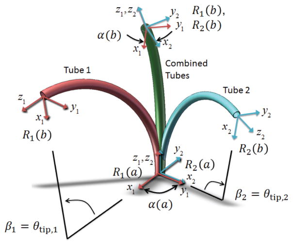
Nevertheless, elastic instability imposes significant constraints on robot and workspace design. An important example, shown in Fig. 1, is comprised of a pair of tubes of equal stiffness and equal constant precurvature. By rotating these tubes at their base, the combined curvature varies from the maximum precurvature value to zero. The latter configuration corresponds to a base rotation angle of π. The tube pair is stable for all relative rotation angles if and only if the following condition is met [12], [1]:
| (1) |
Fig. 1.
Effect of torsional twisting when two curved tubes are combined. Tube coordinate frames are denoted by Ri(s). The relative z-axis twist angle between frames α(s) varies from a maximum α(a) at the base to a minimum α(b) at the tip. The central angles βi = θtip,i are proportional to the precurvature and to the tube length L = b – a.
Here L is the tube length, ν is the Poisson’s ratio of the tubes, and ûi and βi are the precurvature and central angle of tube i, respectively. Reference [13] extended this condition to include straight transmission, and proposed an implicit method to design a stable robot with more than two tubes. A bifurcation and energy-based analysis to measure local elastic stability are presented in [14], and more general mathematical conditions for local elastic stability of tubes with arclength-varying curvatures in the presence of external loads are derived in [15].
Viewed from different design perspectives, this stability condition places bounds on either the tube length L, the precurvatures, ûi, or the central angles, βi. In particular, two tubes of equal precurvature and Poisson’s ratio ν = 0.3, are globally stable for maximum tip orientation angles, β1 = β2, that are less than 79°. There are many clinical applications, however, for which it is desirable for tip orientations to vary smoothly between ±90° or even a wider range. Consequently, the development of techniques to increase the stability of concentric tube robots is important to expanding their clinical utility.
Based on (1), two possible approaches to enhancing stability are (i) to vary the tube properties so as to modify Poisson’s ratio, or (ii) to consider precurvatures that vary with the arc length. Studies based on the former approach include [10], [11], where tubes are modified by, e.g., laser cutting, to reduce their bending stiffness without substantially affecting their torsional stiffness. The latter approach of precurvature optimization was first proposed in [16], where a linear ODE-based stability condition for varying precurvature is presented, and used to numerically optimize a planar tube pair design for maximum elastic stability. It is shown there that, by employing tubes with precurvatures that vary with arc length, the tip orientation angle, β, can exceed the stability limit given by (1).
In this paper we expand on [16] by including the following additional contributions. First, we provide a generalization of the stability condition (1) to include straight transmission segments of different length for each tube. Second, we eliminate the constraint of our prior stability condition that both tubes be of equal precurvature and stiffness and instead require only that the planar precurvature of both tubes be in the same direction along their lengths. Also, each tube must be of constant stiffness along its length, but the stiffnesses and Poisson’s ratios of the tubes can be different. Third, we introduce a nondimensionalization of the optimal control problem formulation that allows us to treat the product of maximum curvature and tube length as a single variable. Fourth, we derive an analytic formulation to the maximally-stable precurvature problem that satisfies the necessary conditions for optimality and show that it agrees with the numerical solution. The analytic solution also provides a new upper bound on stable tip orientation angle for tube pairs of given total length, transmission length and stiffness. Finally, we demonstrate using physical experiments the enhanced stability of tube pairs with our optimized precurvature in comparison to tube pairs of constant precurvature.
The remainder of the paper is organized as follows. Section II reviews our mechanics-based model for the tubes, while the subsequent section presents the kinematics for the special case of planar tube pairs. A necessary and sufficient condition for evaluating the stability of a tube pair with non-constant precurvatures in derived in Section III. Examples of stability evaluation for two analytically-prescribed precurvature functions are presented in Section IV. Section V formulates the selection of precurvatures as an optimal design problem, and provides both analytic and numerical solutions. This section also provides a comparison of the stability limits of constant-and optimal-precurvature tube pairs. An experimental comparison of tube pair stability appears in Section VI. Conclusions are provided in the final section of the paper while details of the stability condition, derivation of the analytic solution, and experimental calculations appear in three appendices.
II. Kinematics of Tube Pairs with Planar Precurvature
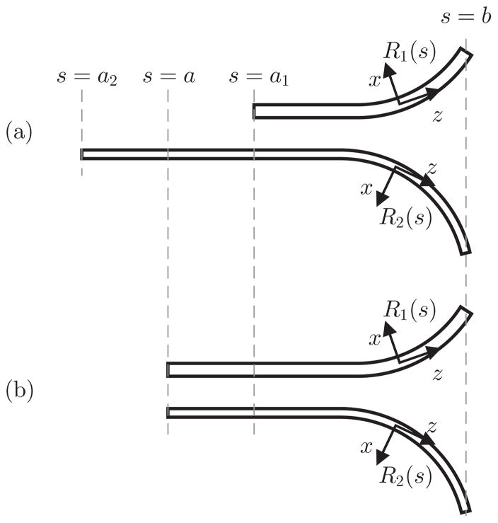
To analyze elastic stability, it is possible to use a reduced kinematic model that considers only the relative rotation between tubes along their length. These equations are a subset of the general robot kinematics that describe the pose of the robot which can be found in [1]. Consider a pair of tubes shown in Fig. 2 (a). Let tube 1 and tube 2 denote the outer and inner tubes, respectively. Suppose that tube i exists over the interval s ∈ [ai, b] as shown in Fig. 2 (a), where s is the arc length parameter. Note that we do not explicitly define where the origin s = 0 is since the kinematics do not depend on the location of the origin. Without loss of generality, the tubes are assumed to be aligned at the tip when combined. If one tube extends beyond the tip of the other, the extended portion does not interact with the other tube, and can thus be ignored in the context of stability.
Fig. 2.
Tube pairs considered in kinematics. The tube pairs (a) and (b) are equivalent in terms of the solutions of the kinematics, where the new base location s = a is computed by (16).
Let Ri(s) ∈ SO(3) denote the material coordinate frame of tube i at s, which is a body frame of tube i at s. The frame Ri(s) is chosen to have its z-axis tangentially aligned to the tube, and y-axis perpendicular to the plane in which the tube lies. Now α(s), the relative rotation between tubes at s, is defined by the angle from R1(s) to R2(s) about their (common) z-axis, i.e.,
| (2) |
where Rz(α) is rotation matrix for rotation of α about the z-axis. Let ûi(s) ∈ ℝ3 and Ki ∈ ℝ3×3 denote the three-dimensional precurvature vector at s and the stiffness tensor, respectively, where
Note that the first and second diagonal components of Ki are the same since the cross sections of the tubes are assumed to be circular.
Using the notation of Fig. 2, the kinematics of the tube pair can be derived from the two-tube case of the concentric tube robot kinematics given in [1], i,e.,
| (3) |
| (4) |
| (5) |
| (6) |
where uix, uiy are x- and y-bending curvatures of the combined tubes expressed in the material coordinate frame of tube i, and uiz is mechanical twist rate of tube i. Substituting (4) into (5) yields
| (7) |
From (3) and (6), α̇ is given by
| (8) |
and combining (7) and (8) yields an ODE
| (9) |
with the boundary condition
| (10) |
where k̃ is defined by
| (11) |
When the tubes are made of the same material with Poisson’s ration ν, then k̃ reduces to k̃ = 1+ν by substituting kix/kiz = 1 + ν into (11).
Note that (9) applies only for s ∈ [a1, b] where both tubes exist. For s ∈ [a2, a1), tube 2 is subject to the base torque only, and experiences a constant twist rate. Let Δθ denote the twist angle accumulated in this interval. Then Δθ is given by
| (12) |
| (13) |
Defining the base rotation α0 as the relative rotation of the base frames of the tubes, i.e., R1(a1) and R2(a2), about their (common) z-axis, α(a1) is then sum of α0 and Δθ, i.e.,
| (14) |
This equation is another boundary condition for the ODE (9) when the base rotation α0 is given as the kinematic input.
Now consider new tubes obtained by straightly extending the outer tube and shortening the inner tube, as depicted in Fig. 2 (b), so that they both have the same base location at s = a. Since both tubes does not interact from s = a to s = a1, they are constantly twisted. Then the boundary condition for these new tubes is given by
| (15) |
When a is chosen to be
| (16) |
the boundary conditions for the original tube pair and the new tube pair in (14) and (15), respectively, become identical. Note that (16) can also be derived from the elastic energy equivalence between the two tube pairs in Fig. 2. Then, given the same base rotation α0, the sets of kinematic solutions α(s) for both tube pairs are identical over s ∈ [a1, b] based on the kinematics and boundary conditions. This equivalence allows us to derive a stability condition and to formulate the optimal design problem for the tube pair in Fig. 2 (b) to obtain the solution for the tubes of Fig. 2 (a).
III. Stability Condition for Planar Tube Pairs
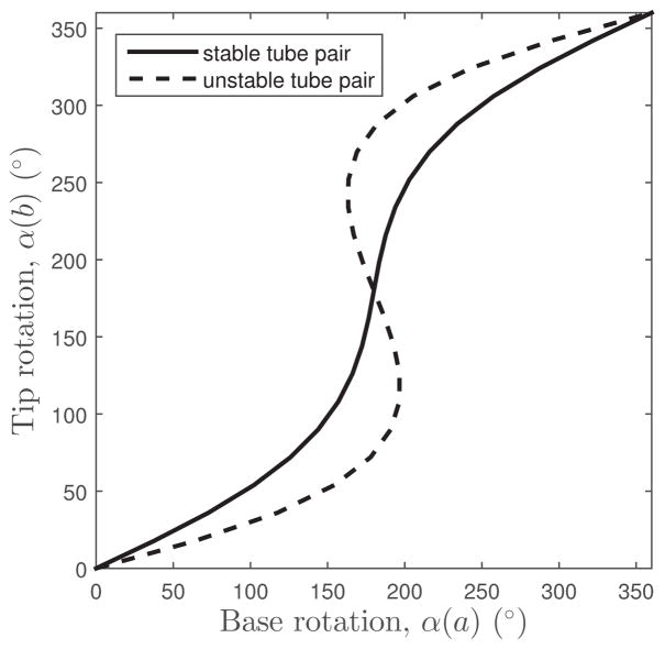
The stability condition of (1) applies for tube pairs of constant precurvature and was derived in [1] based on the uniqueness (stable) or nonuniqueness (unstable) of the solution to the kinematic equations. Stability can be presented graphically by plotting relative tube rotation at the base versus the tip and examining solution multiplicity as shown in Fig. 3. While such a plot can be numerically calculated for tube pairs of arbitrary curvature and then inspected to determine stability, this approach is computationally intensive.
Fig. 3.
Example plots of relative tube rotation at the base versus the tip for tubes of constant precurvature. The solid curve possesses a unique tip rotation for each base rotation and so is stable. The dashed curve, comprised of tubes of higher precurvature, possesses multiple tip rotations for a range of base rotations and so is unstable.
As an alternative analytical approach for tubes of varying precurvature, a new stability condition was derived in [16] that is based on the fact that the tip rotation is unique for a given base rotation if and only if the curve is monotonically increasing, under the assumptions that the precurvatures and stiffnesses of both tubes are equal.
In this section we present a generalized stability condition. Instead of requiring both tubes to have equal stiffness and precurvature, we only assume that the precurvatures satisfy an inequality
| (17) |
over the entire length, which is required for the proof of the stability condition presented in Appendix A. This condition only requires both tubes to be curved in the same direction at every point on the length.
Using the notation of Fig. 2, the condition for the curve of Fig. 3 to be monotonically increasing can be written as
| (18) |
Since evaluation of this expression involves solving a boundary value problem using the split boundary conditions
| (19) |
we use the equivalent reciprocal expression and due to symmetry, we need only consider half the interval:
| (20) |
In this form, we can evaluate it by integrating backward in arc length from b to a using the boundary conditions:
| (21) |
Our stability condition based on (20) and derived in Appendix A is given by the following proposition.
Proposition 1
Let α(s) denote the solution to (9) and (21) If û1y(s)û2y(s) ≥ 0, the condition
| (22) |
is equivalent to
| (23) |
This proposition substitutes evaluation of the entire curve in Fig. 3 with a single evaluation at the tip rotation angle of α(b) = π. Stability evaluation can be further simplified by considering the linear differential equation
| (24) |
with boundary conditions
| (25) |
These equations are obtained by differentiating (9) and (21) with respect to α(b) at α(s) = π. If the solution to (24)–(25) is always positive over s ∈ [a, b], the tube pair is stable. This allows us to determine the stability of a given tube pair by examining the solution of a linear differential equation for a set of specific boundary conditions.
IV. Evaluating Stability for Specific Precurvature Functions
The stability condition presented above can be used to evaluate the stability of particular precurvature functions. Two examples are provided here. The first consists of a pair of tubes with distal sections of constant curvature and straight proximal transmission sections. The second example considers precurvatures of the form with {p, q} ∈ ℝ+.
A. Constant precurvature with Proximal Straight Transmission Lengths
Tube pairs often have straight transmission lengths at their base as depicted in Fig. 2. While they do not bend, these straight sections do twist and contribute to instability. Consider the case when their precurvature functions are given by
| (26) |
| (27) |
Defining l̄ as l̄ = max(l1, l2), the solution to (24) is given by
| (28) |
where c is defined by
| (29) |
and k̃ given in (11). Then stability condition (23) reduces to
| (30) |
where L is the tube length, i.e., L = b – a.
This equation is a generalized form of (1), the stability condition for constant precurvature tubes without transmission lengths. To recover this simpler form, we can set l̄ to 0 and assume the same material for both tubes resulting in the right side of (30) converging to π/2 and k̃ in c becoming k̃ = 1+ν where ν is Poisson’s ratio. Then the condition (30) reduces to
| (31) |
B. Precurvature Function, ûy = q/(s + p)
Consider a precurvature function with scalars p > –a and q > 0. The analytic solution to (24) is given by
| (32) |
where
When , it is easily shown that for α(b) = π and s ∈ [a, b]; In other words, it can be verified that the tube pair is stable simply by checking and for α(b) = π. This implies that any precurvature with (p, q) satisfying can be used for a stable tube pair. Since c0 is invariant to p, the choice of p is unbounded as long as p > –a. Defining the central angle θdes swept out by the initial curvature of the tubes as
an arbitrarily large θdes can be achieved by selecting p to be larger than, but very close to –a. From a theoretical perspective, this result is quite meaningful, since the swept angle θdes was bounded by the inequality (31) for the constant precurvature case. In practice, it is hard to achieve due to the yield strain of the material, which bounds the magnitude of precurvature.
On the other hand, when , the following inequality must hold in order to satisfy :
Noting that the left side attains a minimum at s = a, the inequality reduces to
| (33) |
where L = b – a is tube length.
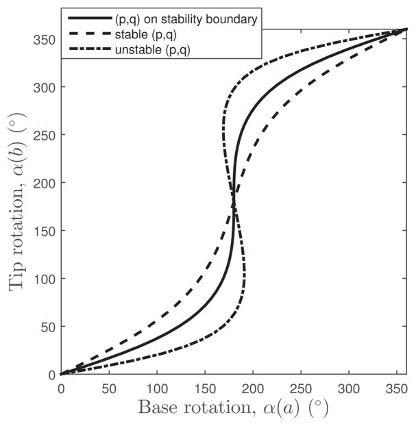
Inequality (33) serves as the general stability condition for precurvatures of the form, . This condition can be validated by plotting α(a) versus α(b) curves for various (p, q) pairs. Some examples are given in Fig. 4. To plot each curve in the figure, α(b) is discretized into 21 values between 0 and 2π and given as boundary conditions for the general kinematic equations of [1]. As anticipated, pairs (p, q) that satisfy the stability condition (33) produce monotonically increasing curves. Pairs (p, q) on the boundary of the inequality (33) produce a curve of infinite slope at (α(a), α(b)) = (π, π). Unstable pairs produce negative slopes over some portions of their curves.
Fig. 4.
Base rotation versus tip rotation curves for various (p, q) pairs.
V. Optimal Design of a Tube Pair
Given a pair of tubes sharing linearly dependent precurvature functions, i.e.,
| (34) |
where η > 0 is a given constant, and of potentially different constant stiffnesses, we are interested in solving for the precurvature that will be most stable. One can choose arbitrary η, though η = k2x/k1x is recommended for the tube pair to be straight at α(a) = π. Our prior work considered optimizing over precurvatures defined by a specified function, e.g., solving for the most stable values of {p, q} in û1y(s) = û2y(s) = q/(s + p) [16].
Here, we formulate the design optimization problem as an optimal control problem and present a precurvature function that satisfies the necessary conditions for optimality. The design problem is defined to produce the most stable design such that the tip tangent direction can vary between 0 and θdes as the tubes are rotated while bounding the precurvature by a given upper bound.
This section is arranged as follows. First, the optimization criteria and constraints are defined. In the next subsection, the equations are nondimensionalized. Then, the necessary conditions for optimality are presented together with a precurvature function that satisfies them. The following subsection employs steepest descent to solve numerically for the optimal solution and it is shown that these results agree with the identified optimal precurvature function. Based on these results, we compute the maximum stable tip angles and compare them with what can be achieved with constant precurvature.
A. Optimization Criteria and Constraints
The design problem is to solve for a pair of tubes that can stably produce tip tangent angles in the range [0, θdes]. First, let us define the combined precurvature ûy(s), i.e,
| (35) |
From (34) and (35), ûy(s), û1y(s) and û2y(s) satisfy
| (36) |
We choose ûy(s) as the optimization variable, while any of them could be chosen as they are dependent. Then the maximum tip angle is given by
| (37) |
In practice, arbitrarily high precurvatures cause tubes to buckle during shape setting or during the relative rotation of the combined tubes. Thus, precurvature must be bounded to a physically realizable value. For example, the shape setting involves bending straight tubes in desired shapes. In this procedure, a precurvature bound may be specified based on maximum allowable bending strain, ε̄,
| (38) |
in which di is the outer diameter of tube i. This induces an upper bound of ûy based on (36) of the form
| (39) |
A tube pair is stable if and only if the solution to (9), (10) and (21) satisfies (22). Since the stability boundary corresponds to equality in this expression, maximizing stability equates to maximizing the minimum value of over α(b) ∈ [0, π]:
Noting that is the inverse of the slope of the curves in Fig. 3, the above optimization straightens the curves between (0, 0) and (π, π) by maximizing the minimum inverse slope.
If the design is stable then for α(b) ∈ [0, π] and, based on Proposition 3 in Appendix A, its minimum value is given by
| (40) |
Based on this equation, the design problem can be stated as:
Design Problem
Solve for
| (41) |
subject to the constraints
| (42) |
| (43) |
| (44) |
| (45) |
where s = t is the end of the straight transmission, and the last constraint ensures stability by Proposition 1.
B. Nondimensionalization
As stated above, the design problem depends on four tube parameters: their total length, their straight transmission length, the desired maximum tip tangent angle, θdes, and the maximum curvature, ûmax. Noting that ûmax has units of inverse length, the length parameters and curvature parameters in the problem can be nondimensionalized by multiplying or dividing by ûmax, respectively. The value of nondimensionalization is that the optimal solution, as shown graphically in Section V-E, can be expressed as a function of three rather than four parameters.
Dimensionless variables for arc length, s̃, total tube length, L̃ , straight transmission length, T̃, and precurvature, ũy(s) are defined as follows.
| (46) |
| (47) |
| (48) |
| (49) |
The dimensionless form of the stability equation (24) and boundary conditions (25) are given by
| (50) |
| (51) |
where κ is given from (36) by
| (52) |
The dimensionless design problem can be stated as
Dimensionless Design Problem
Solve for
| (53) |
subject to
| (54) |
| (55) |
| (56) |
| (57) |
C. Analytic Solution to Optimal Design Problem
It is sometimes possible to solve the design problem (53) analytically for a specified precurvature function. For example, an analytic solution to the design problem is presented in [16] for the precurvature function .
Alternatively, we can attempt to solve for the optimal functional form by considering the dimensionless design problem of Section V-B as an optimal control problem with control variable ũy(s̃). This problem is solved analytically in Appendix B, where the first-order optimality condition is applied based on [17]. The solution is given in two forms depending on whether θdes is greater than θref or not, where θref is defined in (129):
-
If θdes > θref,
(58) where c1, v and w are given in (122)–(123), and the saturation point l is computed by root-finding of (125) for a given θdes.
-
If θdes ≤ θref,
(59) where c1, v and w are given in (126)–(127). The unknown ũ0 is the optimal precurvature value at s̃ = T̃, i.e., ũy(T̃) = ũ0. This unknown is computed by root-finding of (128) for a given θdes.
Since this solution satisfies the first-order necessary condition for optimality, it could be either a minimizer, a maximizer, or just a saddle point. To answer this question, the analytical solution is compared with the numerically-obtained optimal solution below.
D. Numerical Solution to Optimal Design Problem
In this section, the steepest descent method from optimal control, described in [18], is applied to generate numerical solutions, and the numerical solutions are compared with the analytic solution (58)–(59). For notational simplicity, we define
| (60) |
The Hamiltonian is given by
| (61) |
in which x(s̃) = (x1(s̃), x2(s̃)) and p(s̃) = (p1(s̃), p2(s̃)) are the state and co-state variables, respectively, that satisfy
| (62) |
The update direction in the steepest descent method is then given by
| (63) |
where x1(s̃) and p2(s̃) are computed from the state and co-state equations for a given ũ(s). In the numerical implementation, the constraints (54)–(56) are given as linear constraints of the form
| (64) |
| (65) |
| (66) |
where N is the dimension of ũy discretized by the step size Δs̃, is its i-th component, and M is the largest step index in the transmission length. Then dℋ/dũy is the N-dimensional gradient vector of the cost (53), which can be computed by solving the initial value problems (62) and then substituting x1 and p2 into (63).
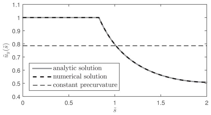
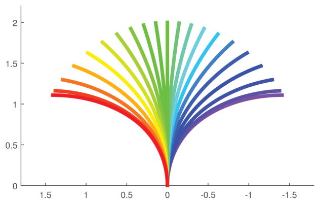
As an example, the numerical and analytical solutions are compared for parameter values L̃ = 2, T̃ = 0, κ = 1.3 and θdes = 90° in Fig. 5. This corresponds to a pair of curved tubes with no straight transmission length and a Poisson’s ratio of 0.3. Notice that the solutions agree and that the analytical solution is that of (58) in which the curvature along the proximal length is saturated at the maximum value and decreases with increasing arc length. If the tubes are equally stiff and precurved, they remain planar for all relative rotation angles and produce the shapes depicted in Fig. 6.
Fig. 5.
Analytic and numerical solutions of optimal precurvature for L̃ = 2, T̃ = 0, κ = 1.3 and θdes = 90°. The constant curvature corresponding to the average curvature of the optimal design is also shown.
Fig. 6.
Planar shape of optimal tube pair as relative rotation angle is varied. Tube parameters are L̃ = 2, T̃ = 0, κ = 1.3 and θdes = 90°. The tubes are assumed to be equally stiff and equally precurved.
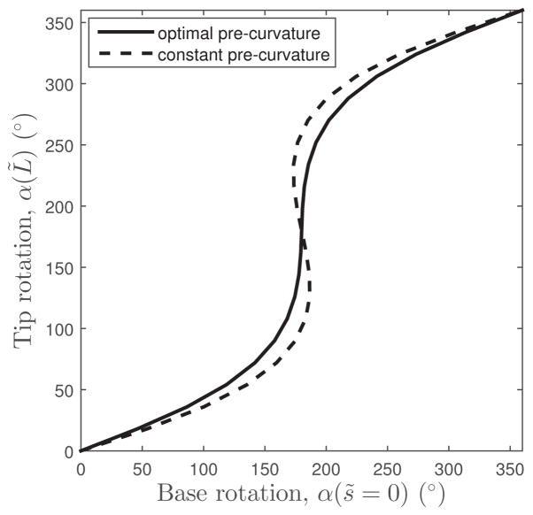
To investigate the relative stability of the optimal solution, consider a constant curvature tube pair with the same tip rotation angle θdes = 90°. The value of constant curvature equates to the average curvature over the length of the optimal tube pair and is shown in Fig. 5. A comparison of base and tip rotation angles for the two designs is shown in Fig. 7. As described in the introduction, the constant curvature pair will be unstable for any θdes > 79° at this value of Poisson’s ratio. The optimal design is stable, however, as seen from its non-negative slope.
Fig. 7.
Base rotation versus tip rotation of optimal- and constant-precurvature tube pairs. Tube parameters are L̃ = 2, T̃ = 0, κ = 1.3 and θdes = 90°.
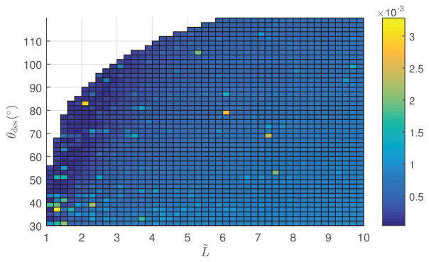
Based on our observations, the numerical solution always converges to the analytic solution. As an illustration, the error between the analytic and numerical solutions is plotted as a function of tube length and tip angle in Fig. 8. Error is defined by
Fig. 8.
Average curvature difference between analytic and numerical optimal precurvatures as a function of L̃ and θdes for T̃ = 0 and κ = 1.3.
| (67) |
where ũy,a and ũy,n denote the analytic and numerical solutions, respectively. This figure shows that the average difference in precurvature is less than 0.4% of the maximum precurvature.
The empty region in the upper-left corner of parameter space in Fig. 8 is where no analytical solution exists and where the numerical method fails to find a stable solution. The curve bounding this region represents the stability limit and is investigated below.
E. Stability Limit
The stability limit of the swept angle has been presented for constant precurvatures in [1]. This section presents a new stability limit based on the optimal precurvature presented in Section V-C. This gives a new upper bound on the swept angle for stable tube pairs, given the tube length L, straight transmission length t, and maximum precurvature umax.
Suppose that L̃ is small enough that the maximum constant precurvature solution is stable, i.e., the dimensionless form of (30) is satisfied:
| (68) |
When this inequality holds, the maximum stable tip angle, θlimit, is given by
| (69) |
If, however, L̃ is too large to satisfy (68) then the stability limit must be derived based on the optimal precurvature solution. Since we are interested in the upper bound of θdes, we will focus on the solution (58), which is for θdes larger than θref. Using the notation of (60) and substituting (58) into (24) yields
| (70) |
where a scalar c2 can be computed straightforwardly from the boundary condition x1(L̃) = 1, while the explicit form is unnecessary here. From (50) and (51), x1(s̃) is a non-decreasing function if the stability condition
| (71) |
holds. Thus, x1(s̃) is minimum at s̃ = 0 and the stability boundary corresponds to
| (72) |
| (73) |
After algebraic manipulations with x1(s̃) in (70), the conditions (72) and (73) reduce to
| (74) |
| (75) |
where τ is defined in (124).
Defining θlimit as the stability limit of swept angle, it can be calculated by root finding of (74) as presented in Table I.
TABLE I.
Computation of Stability Limit
| θlimit = STABILITY LIMIT(L̃, T̃,κ) |
|---|
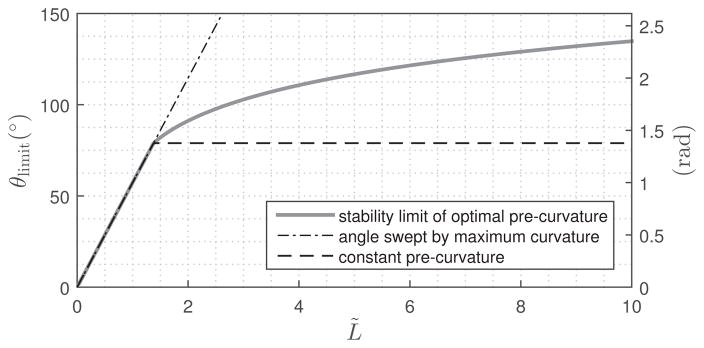
Fig. 9 provides a comparison of stable tip angles for optimal- and constant-precurvature tube pairs by plotting θdes versus normalized tube length, L̃. Note that dimensionless tube length L̃ = ûmaxL equates to the tip angle in radians of a tube pair designed with maximum precurvature, ûmax. Thus, tubes of precurvature, ûmax, are described by a line of unit slope when tip angle is expressed in radians. (See the right y-axis in Fig. 9.) For L̃ ≤ 1.38rad (79°), this line separates unstable designs (above) from stable designs (below). For larger values of L̃, however, tube pairs with maximum precurvature along their entire length will be unstable. Consequently, the stability boundary for L̃ > 1.38 lies below this line and is defined by the stability limit obtained as described in Table I.
Fig. 9.
Stability limits of optimal precurvature and constant precurvature varying with L̃ when T̃ = 0 and κ = 1.3.
If one wishes to make stable tube pairs of constant precurvature longer than L̃ > 1.38, they must lie on or below the horizontal dashed line shown in the figure. Designs on this line will produce the maximum stable tip angle θdes = 1.38rad (79°), but their constant precurvature will be less than the maximum, ũy(s) = θdes/L̃.
The optimal solution enables the design of tube pairs with significantly larger tip angles. Furthermore, the region between the horizontal dashed line and the solid curve corresponds to the new stable designs revealed by this paper.
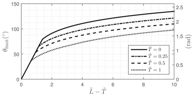
Fig. 10 shows the effect on the stability limit of adding straight transmission lengths, T̃, to the tube pairs. The effect of increasing T̃ is to reduce the maximum stable length of maximum constant curvature tube pairs and to shift the curved portion of the stability limit downward. The transition point can be computed from (68).
Fig. 10.
Stability limit of optimal precurvature varying with L̃ and T̃ when κ = 1.3.
VI. Experiments
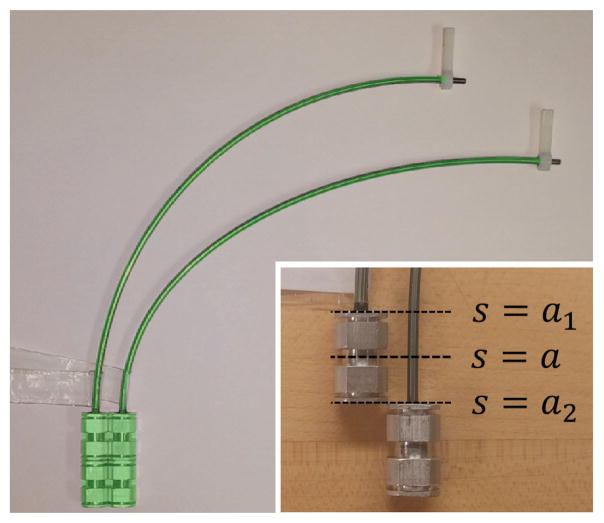
To validate our results experimentally, an optimal design tube pair was compared with a constant precurvature tube pair for a desired tip angle of θdes = 97.4°. This tip angle exceeds the stability limit for constant precurvature and is close to the stability limit of the optimal design for the tube parameters given in Table II. The tubes were shape set in a grooved template fabricated using an NC milling machine. The tube pairs are shown in Fig. 11. Since they relax during use, the shapes of the tube pairs do not exactly match the design parameters in Table II. However, they closely match the optimal shape associated with the relaxed parameters also given in in Table II, θdes = 94° and ûmax = 1/70mm−1, as shown in Fig. 11.
TABLE II.
Tube Parameters
| Length, L (mm) | 200 | |
| Collar Length, a1 – a2 (mm) | 17 | |
| OD (mm) \ ID (mm) | Tube 1 | 2.540 \ 2.248 |
| Tube 2 | 2.083 \ 1.321 | |
| Swept Angle, θdes (°) | Design parameter | 97.4 |
| Relaxed parameter | 94 | |
| Maximum tube precurvature, ûmax (mm−1) | Design parameter | 1/65 |
| Relaxed parameter | 1/70 | |
| Curvature of Constant Precurvature Tube Pair, (mm−1) | 1/117.65 | |
| Theoretical Value of Relative Stiffness, kx1/kx2 and kz1/kz2 |
1.019 | |
| Poisson’s Ratio, ν | 0.3 | |
Fig. 11.
Constant (left) and optimal (right) precurvature tube pairs. Inset shows transmission length of inner tube that passes through collar of outer tube. Location a can be computed by (16) using parameters of Table II. The theoretical shapes (semitransparent green) for the relaxed parameters are superimposed on the top of the tube pairs.
The relative stiffness is given in the table since it is required to compute a in (16). η in (34) is chosen to be 1 so that the tubes share the same precurvature. Poisson’s ratio ν is also used to compute κ in (11) based on the relation kix/kiz = 1 + ν, where ν = 0.3 given in the table is equilvalent to κ = 1.3. The optimal precurvature is computed using (58).
Two types of experiments were conducted. The first consisted of performing relative rotations of the tube pairs at their bases while measuring the relative rotation at their tips. Rotations comprised one complete clockwise revolution followed by one complete counterclockwise revolution. The goal of this experiment was to produce an experimental version of Figs. 3, 4 and 7 showing base rotation versus tip rotation. The second set of experiments was designed to perform sequences of fine motions in the neighborhood of any instabilities in order to more precisely map their boundaries. Each set of experiments used the experimental methods described below.
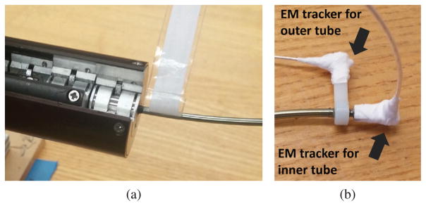
Tube pairs were mounted in a computer controlled motorized drive system as shown in Fig. 12 (a). The drive system was programmed to independently rotate each tube and record base angles. EM trackers (Model 180, Ascension Technologies) were attached to the tip of each tube as shown in Fig. 12 (b) and used to measure orientation. The measurement frequency was 52Hz and the base was rotated at 5°/sec. These measurements are converted off line to relative rotation angles at the tube tips following the method presented in Appendix C.
Fig. 12.
(a) Tube actuation system. Each tube collar is rotated independently by the system. (b) EM sensors attached to tube tips using plastic brackets. Inner tube is slightly longer to allow for mounting.
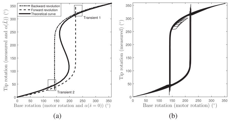
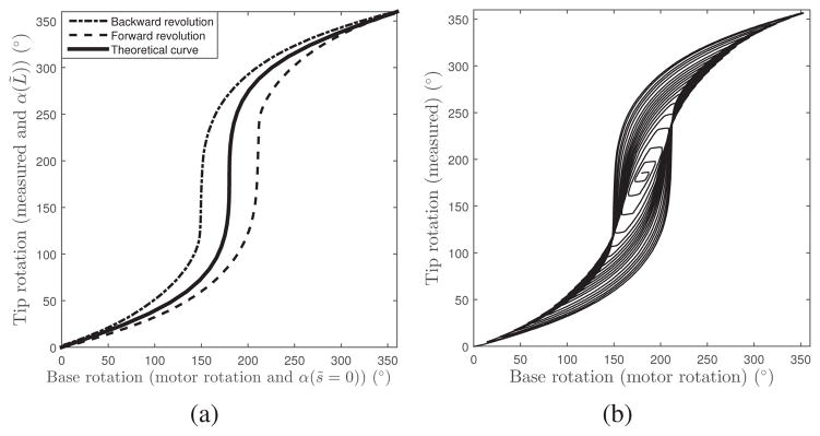
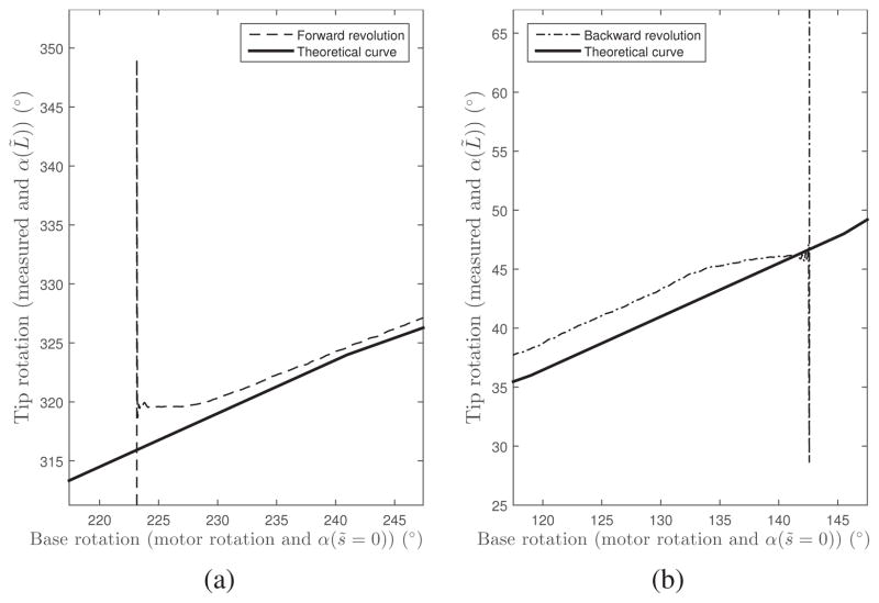
Plots of measured base rotation versus tip rotation for constant precurvature and optimal precurvature are shown, respectively, in Figs. 13 (a) and 14 (a). The analytical solutions are also plotted in these figures. Recall that base motor rotation and measured tip rotation correspond in the dimensionless equivalent tube model to α(s̃ = 0) and α(L̃), respectively. The constant precurvature tube pair exhibits instability as expected. High resolution plots of the transients that follow each unstable jump are given in Fig. 15. In contrast, the optimal precurvature design is stable. As observed in prior work [1], [12], the experimental curves do not follow the theoretical curve, but instead produce a hysteresis loop, likely due to unmodeled phenomena such as friction.
Fig. 13.
Constant precurvature tube pair. (a) Tip rotation in response to complete clockwise and counterclockwise rotations applied at the base. Transients following instabilities are plotted Fig. 15. (b) Tip rotation in response to base rotations described by (76).
Fig. 14.
Optimal precurvature tube pair. (a) Tip rotation in response to complete clockwise and counterclockwise rotations applied at the base. (b) Tip rotation in response to base rotations described by (76).
Fig. 15.
Detailed view of transients indicated in Fig. 13. (a) Transient 1 showing overshoot occurring after unstable jump as relative angle increases. (b) Transient 2 showing overshoot occurring after unstable jump as relative angle decreases.
To investigate whether or not the configurations inside the hysteresis loop are reachable and stable, a second set of experiments was performed. In these experiments, the relative rotation angle at the base of the tubes was commanded as of decreasing amplitude generated by a sequence of set points:
| (76) |
Tip angle in response to this input is plotted for the constant precurvature and optimal precurvature tube pairs in Figs. 13(b) and 14(b), respectively. For the unstable constant precurvature tube pair, it is possible to move inside a small portion of the hysteresis loop by reversing direction before the instability occurs. This can be seen at the top of the loop in Fig. 13(b). A second region is present at the bottom of the loop. In a given trial, the location of the region depends on when the amplitude of the set point commands (76) becomes small enough to reverse the base rotation without causing an unstable jump. Most of the interior of the loop cannot be reached however. In contrast, twist direction can be reversed at any point along the stable loop of the optimal precurvature pair of Fig. 14(b). As a result, all configurations inside the hysteresis loop are reachable and stable.
VII. Conclusion
Prior concentric tube robot designs have considered tubes of piecewise-constant precurvature for reasons of simplicity and also since the combined tube shape is approximately piecewise constant. The results of this paper demonstrate, however, that stability is enhanced for curvatures that decrease with increasing arc length. In particular, the optimal precurvature that maximizes stability and includes the effect of proximal transmission sections has been derived. In comparison with prior stability results for constant tube precurvatures, this approach removes the limits on both tip orientation range and tube length. The price paid for enhanced stability, though, is a larger average robot radius of curvature. In the concentric tube robot design approach proposed in [1] and further developed in [19], robots are designed as telescoping concatenations of variable and fixed curvature sections. Variable curvature sections correspond directly to the planar tube pairs considered in this paper. Consequently, the new stability results can be directly incorporated into this design framework to create designs with larger stable workspaces.
Acknowledgments
This work was supported by the National Institutes of Health under Grant R01HL124020. The work of J. Ha and F. C. Park was supported in part by the SNU BMRR Center (DAPA-UD130070ID), SNU-IAMD, BK21+, and MI Technology Innovation Program (10048320).
Biographies
Junhyoung Ha received his B.S. and Ph.D. degrees in mechanical engineering from Seoul National University, Seoul, Korea, in 2008 and 2015, respectively. During the Ph.D. study, he was a research assistant for the Robotics Laboratory in the School of Mechanical and Aerospace Engineering at Seoul National University. He is currently with Boston Childrens Hospital, Harvard Medical School, Boston. His research interests are in medical robotics, continuum robots, control and optimization.

Frank C. Park (F’13) received his B.S. in electrical engineering from MIT in 1985, and Ph.D. in applied mathematics from Harvard University in 1991. From 1991 to 1995 he was assistant professor of mechanical and aerospace engineering at the University of California, Irvine. Since 1995 he has been professor of mechanical and aerospace engineering at Seoul National University, and also an adjunct professor of electronic and computer engineering at HKUST since 2016. His research interests are in robot mechanics, planning and control, vision and image processing, and related areas of applied mathematics. He is a fellow of the IEEE, current editor-in-chief of the IEEE Transactions on Robotics, and developer of the EDX course Robot Mechanics and Control I, II.

Pierre E. Dupont (M’99-SM’03-F’11) received the B.S., M.S., and Ph.D. degrees in mechanical engineering from Rensselaer Polytechnic Institute, Troy, NY, USA, in 1982, 1984, and 1988, respectively. From 1988 to 1990, he was a Postdoctoral Fellow with the School of Engineering and Applied Sciences, Harvard University, Cambridge, MA, USA. He was a Professor of mechanical engineering and biomedical engineering with Boston University, Boston, MA. He is currently the Chief of Pediatric Cardiac Bioengineering with Boston Childrens Hospital, Harvard Medical School, Boston, where he is involved in developing instrumentation and imaging technology for minimally invasive surgery.
Appendix A. Proof of Proposition 1
We first prove the following two propositions:
Proposition 2
Let α(s) denote the solution to (9) and (21). Then
| (77) |
if and only if
Proof
The backward direction is obvious, requiring only proof of the forward direction. For notational simplicity, is replaced by . Differentiating (9) and (21) with respect to α(b) yields a linear ODE
| (78) |
with boundary conditions
| (79) |
When α(b) = 0, the solution to (9) and (21) is α(s) = 0. In this case, (78) reduces to
Given the boundary conditions (79) together with a positive value of , x(s)|α(b)=0 results in a decreasing function over s ∈ [a, b], which satisfies x(s)|α(b)=0 ≥ 1.
Suppose there exists a solution to (78), x(s)|α(b)=γ, which is not always positive in s ∈ [a, b]. Differentiating (78) again with respect to α(b) yields
Since this is also a linear ODE in for which the system input is associated with x(s), it leads to a finite value of for a finite x(s). Consequently, x(s) as well as its minimum value over s ∈ [a, b] is continuously varying over α(b) ∈ [0, γ]. Since the minimum value of x(s)|α(b)=γ is not positive while that of x(s)|α(b)=0 is 1, there exists at least one α(b) between 0 and γ for which the minimum value of x(s) is zero. Let α(b) = β and s = c denote this α(b) and corresponding minimizer, respectively. Then
| (80) |
By (77) and (79), c is neither a nor b. The first-order necessary condition for the minimizer c which is not on the boundary of the domain s ∈ [a, b] is given by
| (81) |
However, this is not possible since the only solution to (78) given (80) and (81) is a constant function x(s)|α(b)=β = 0, which does not satisfy the boundary condition (79). Thus, there does not exist any solution to (78) that is not always positive in s ∈ [a, b].
Proposition 3
Let α(s) denote the solution to (9) and (21). If
| (82) |
then it satisfies
for any s ∈ [a, b] and α(b) ∈ [0, π].
Proof
Let x(s) denote again. By differentiating (9) and (21) with respect to α(b), the same equations (78)–(79) are obtained. When α(b) = π, the solution to (9) and (21) is α(s)|α(b)=π = π. In this case, Equation (78) reduces to
The proposition is clearly satisfied when s = b or α(b) = π. Suppose there exists s = c ∈ [a, b) and α(b) = β ∈ [0, π) that does not satisfy the proposition, i.e.,
| (83) |
Since x(s)|α(b)=π is positive over s ∈ [a, b] by (82), the following inequality holds:
| (84) |
for s ∈ [a, b]. By (79) and (83), the following inequalities hold as well:
| (85) |
The inequalities (84)–(85) are the conditions for x(s)|α(b)=π to be an upper solution to x(s)|α(b)=β over s ∈ [c, b] [20]. It has been proven that any solution to an ODE lies below the upper solution. However, because of the same boundary conditions x(b)|α(b)=β = x(b)|α(b)=π = 1, ẋ (b)|α(b)=β = ẋ(b)|α(b)=π = 0 and the smaller value of the second derivative at s = b, i.e.,
it follows that x(s)|α(b)=π cannot be the upper solution near s = b. This can be shown via a Taylor expansion for a small positive scalar ε around s = b:
Since there is a contradiction between (82) and (83), there does not exist any c ∈ [a, b) and β ∈ [0, π) satisfying (83) if (82) holds.
The forward direction of Proposition 1 is satisfied straightforwardly by Proposition 2. The backward direction is also satisfied by Proposition 3, i.e.,
Appendix B. Derivation of Solution to Dimensionless Design Problem
This appendix presents the derivation of the analytic solution from the the first-order optimality conditions of the dimensionless design problem (53)–(57). Again, for notational simplicity, we define
Let the prime notation denote the derivative with respect to s̃, for instance, . Then (24) and (25) are written as
| (86) |
and the dimensionless design problem (53)–(57) reduces to
| (87) |
subject to
| (88) |
| (89) |
| (90) |
| (91) |
A small positive scalar ε, such that 0 < ε ≪ 1, is introduced to cast the open inequality (57) to a closed inequality (91) to include it in an optimal control problem. The above problem is then an optimal control problem with the state variable x = (x1, x2) and the control variable ũy.
The integral and control constraints (88)–(90) are directly augmented with the Hamiltonian with Lagrangian multipliers, while the state constraint (91) should be decomposed into a control and point constraints by differentiating it with respect to s̃ until ũy is explicitly shown [17]. The decomposed constraints are given by
| (92) |
| (93) |
| (94) |
where [s̃1, s̃2] is an unknown interval where the optimal path is on the boundary of (91), and s̃p is any point in [s̃1, s̃2]. The next step in general is to augment them with the Hamiltonian and end point function using Lagrangian multipliers. While the first-order optimality condition outside the interval [s̃1, s̃2] is identical to the case without the constraint, a set of specific optimality conditions should be applied to this interval to find the constrained optimal path as well as the unknowns s̃1 and s̃2 [17]. In our case, however, we could skip this step since there does not exist the interval [s̃1, s̃2] that satisfies (93) and (94) together. This can be proven as follows: from (86) and (91), x1 is a non-decreasing concave function and x2 is non-increasing function such that
| (95) |
If there exists [s̃1, s̃2] that satisfies (93) and (94), then there exists s̃p such that
| (96) |
The only x1 and x2 that satisfy (95) and (96) are the constant functions, x1 = ε and x2 = 0. However, they do not satisfy the boundary condition in (86). Thus there does not exist [s̃1, s̃2] that satisfies (93) and (94) together.
Consequently, we need to consider the Hamiltonian adjoined with the constraints (88)–(90) only, of the form
| (97) |
where the regular Hamiltonian is
| (98) |
Here, μ is a constant, λi are functions of s̃ such that λifi = 0 and λ2 ≥ 0, and p = (p1, p2) is co-state variable. The optimality conditions are then given by
| (99) |
with (86). Substituting (97) into (99) yields
| (100) |
| (101) |
We omitted the equation for s̃ ∈ [0, T̃) from (100) since it is obvious from (89) that the optimal control is given by
| (102) |
Now we would like to show that p2 is a negative decreasing function over s̃ ∈ [T̃, L̃]. Consider the following second-order ODEs for x1 and p2 derived from (86) and (101):
| (103) |
| (104) |
Defining and , (103)–(104) reduce to
| (105) |
Suppose that y1 and y2 intersect at s̃ = σ, i.e., y1(σ) = y2(σ). Then y1 and y2 are an identical function since (105) is first-order. The contraposition yields that, if they are not identical, they never intersect. Now let us show that they are not identical. First, note that y1 is a non-negative finite function over s̃ ∈ [0, L̃] by (95). For s̃ = δ ∈ [0, T̃), p2, and y2 are given from (102) and (104) by
| (106) |
Since y1(δ) is finite, y2(δ) > y1(δ) when δ is sufficiently small. Thus y1 and y2 are not identical, never intersect, and thus maintain the order relation y2 > y1 ≥ 0 over s̃ ∈ [δ, L̃]. Finally, p2 is given as a negative decreasing function of the form
| (107) |
Now let us see the sign of μ. From (88), there exists at least one s̃ ∈ [T̃, L̃] such that ũy(s̃) > 0. Thus μ is negative by (100) since 2κũyp2x1 < 0 by positive x1 and negative p2, and λ2 ≥ 0 by definition. Moreover, ũy is always positive over [T̃, L̃] since, otherwise, μ couldn’t be negative by (100).
Until now, we have shown that:
x1 is positive increasing function over s̃ ∈ [T̃, L̃],
p2 is negative decreasing function over s̃ ∈ [T̃, L̃],
μ is a negative constant, i.e., μ < 0,
ũy is a positive function over s̃ ∈ [T̃, L̃].
Keeping these in mind, let us derive the optimal control ũy for s̃ ∈ [T̃, L̃]. Consider the following two cases:
- λ2 > 0: The optimal control is given from λ2f2 = 0 by
(108) -
λ2 = 0: The optimal control is given from (100) by
(109) which is a decreasing function by negative μ, positive increasing x1, and negative decreasing p2.
Note that ũy is continuous at the boundary points between case i) and case ii). It is shown as follows: since μ is the same constant for both cases, the evaluations of (100) for the left and right limits of a bound point are equal:
| (110) |
where case i) and case ii) are assumed to be on the left(−) and right(+) sides of the boundary point, respectively, while this assumption doesn’t affect the generality since the opposite case is given simply by swapping the signs. Noting that x1 and p2 are continuous as they are solutions of second-order ODEs, the above equation reduces to
| (111) |
Since the left side is non-positive and the right side is nonnegative, both sides should be zero, i.e., and . Thus ũy is continuous at the boundary point by .
Consequently, the optimal control ũy over s̃ ∈ [T̃, L̃] is a set of continuous (and possibly multiple) connections of (108) and (109). Recalling that (109) is a decreasing function, there exist only two possible combinations of (108) and (109):
Solution 1) Equation (108) for s̃ ∈ [T̃, l), and (109) for s̃ ∈ [l, L̃], where l is an unknown saturation point.
Solution 2) Equation (109) for s̃ ∈ [T̃, L̃].
Now let us derive explicit from of ũy from (109) by eliminating x1 and p2. Without loss of generality, x1 can be expressed by
| (112) |
where f is unknown function of s̃. Note that this expression does not bound the candidates of ũy and x1 since f always exists for any combination of ũy and x1 as long as ũy and x1 are positive functions. Then p2 is given from (109) and (112) by
| (113) |
Substituting (112) and (113) into (103) and (104), respectively, yields
| (114) |
| (115) |
where c1 and c2 are constants of integration. Introducing a new function g = 1/ũy, the ODE (115) becomes
| (116) |
By differentiating with respect to s̃, (116) reduces to
| (117) |
Thus g is a second-order polynomial that satisfies (116). From straightforward calculations, g is given by
| (118) |
where v and w are new constants of integration. Then ũy becomes
| (119) |
For Solution 1, the five constants μ, c1, c2, v and w can be computed by substituting (112)–(114) and (119) into four boundary conditions in (103)–(104). The fifth equation is given by continuity of ũy at s̃ = l, i.e.,
| (120) |
For Solution 2, (120) can not be used. Instead, one can introduce an unknown value ũ0 ≤ 1 such that ũy( T̃) = ũ0:
| (121) |
Note that l in Solution 1 or ũ0 in Solution 2 is still unknown. They should be determined by θdes from (88). Finally, the constants for both cases are given by
Constants for Solution 1
| (122) |
| (123) |
where
| (124) |
Given θdes, l is determined by
| (125) |
Constants for Solution 2
| (126) |
| (127) |
Given θdes, ũ0 is determined by
| (128) |
Here, c2 and μ are not presented since they are unnecessary to compute ũy in (119). Note that Solution 1 with l = T̃ and Solution 2 with ũ0 = 1 have the same θdes = θref:
| (129) |
If a given θdes is larger than this value, then Solution 1 is optimal. Otherwise, the solution is given by Solution 2.
Appendix C. Relative Rotations from EM Tracker Measurements
The relative rotation of the EM trackers mounted on the robot tips can be described by (see [21]),
where R0 ∈ SO(3), ŵ ∈ ℝ3 and αi ∈ ℝ are the initial relative orientation, the screw axis, and the tip rotation angles, respectively, such that ||ŵ||= 1, and [·] denotes the skew-symmetric representation of a vector in ℝ3. For , the skew-symmetric representation is given by
| (130) |
Also, {Ri}i=1,...,m are the rotation matrices corresponding to the sequence of measurements.
Then R0, ŵ and αi can be computed sequentially by a series of least squares problems. Suppose that there is no noise in the measurements {Ri}i=1,...,m. Then they satisfy
| (131) |
for any i = 1, . . . , m. When there exists measurement noise, one can consider the following least squares criterion:
| (132) |
Note that Ri is known, and that R0 and ŵ are unknowns. One can consider R0 to be known as well by assuming that it is equal to the first measurement of Ri, but we prefer to consider it as unknown so as to avoid the dependency of the optimization result concentrated on the noise of the first measurement. Ignoring the constant term m and switching the overall sign, the least squares problem becomes a maximization of the form
| (133) |
where R0 ∈ SO(3), ŵ ∈ ℝ3 and ||ŵ|| = 1, or equivalently
| (134) |
where ŵ, v̂ ∈ ℝ3 such that ||ŵ|| = ||v̂|| = 1 and v̂ = R0 ŵ.
Applying the standard approach to solve a vector space optimization using Lagrangian multipliers and the first-order necessary conditions, the solutions for ŵ and v̂ are given by the first column vectors of U ∈ ℝ3×3 and V ∈ ℝ3×3, respectively, where U and V are the matrices from the singular value decomposition of , i.e.,
| (135) |
Here U, V and S are sorted by descending singular values.
Now let us compute R0. At this point, there are multiple choices of R0 since any R0 that satisfies v̂ = R0 ŵ is a minimizer of (133). Note that the equation v̂ = R0 ŵ has one-parameter family of solutions of the form
| (136) |
where t ∈ ℝ is the solution parameter and R0,p is a particular solution [22]. One particular solution is given by
| (137) |
which can be easily checked to satisfy R0,p ŵ = v̂ and to be a rotation matrix. Any other particular solution can be used if available. Now R0 can be chosen from the solution family to minimize the difference from R1. The minimization is given by
| (138) |
Here, || · ||F denotes the Frobenius norm defined as where Tr(·) is the trace operator. Substituting the exponential formula presented in [22],
| (139) |
into (138) yields
| (140) |
where
| (141) |
The minimizer of (140) is given by
| (142) |
and R0 is then given by
| (143) |
Once ŵ and R0 are computed, αi can also be computed by a minimization
| (144) |
for each i = 2, · · ·,m. This can be solved in the same way as applied to (138).
Note that all the solutions are in closed form; they are fast and reliable to compute without worrying about local minima.
Contributor Information
Junhyoung Ha, Department of Cardiovascular Surgery, Boston Childrens Hospital, Harvard Medical School, Boston, MA 02115 USA.
Frank C. Park, School of Mechanical Engineering, Seoul National University.
Pierre E. Dupont, Department of Cardiovascular Surgery, Boston Childrens Hospital, Harvard Medical School.
References
- 1.Dupont PE, et al. Design and control of concentric tube robots. IEEE Trans Robotics. 2010;26(2):209–225. doi: 10.1109/TRO.2009.2035740. [DOI] [PMC free article] [PubMed] [Google Scholar]
- 2.Rucker DC, et al. Equilibrium conformations of concentric-tube continuum robots. The International Journal of Robotics Research. 2010;29(10):1263–1280. doi: 10.1177/0278364910367543. [DOI] [PMC free article] [PubMed] [Google Scholar]
- 3.Xu R, Patel R. A fast torsionally compliant kinematic model of concentric-tube robots. Engineering in Medicine and Biology Society (EMBC), 2012 Annual International Conference of the IEEE; IEEE; 2012. pp. 904–907. [DOI] [PubMed] [Google Scholar]
- 4.Anor T, et al. Algorithms for design of continuum robots using the concentric tubes approach: a neurosurgical example. Robotics and Automation (ICRA), 2011 IEEE International Conference on; IEEE; 2011. pp. 667–673. [DOI] [PMC free article] [PubMed] [Google Scholar]
- 5.Burgner J, et al. Debulking from within: A robotic steerable cannula for intracerebral hemorrhage evacuation. IEEE transactions on biomedical engineering. 2013 doi: 10.1109/TBME.2013.2260860. [DOI] [PubMed] [Google Scholar]
- 6.Vasilyev NV, et al. Tissue removal inside the beating heart using a robotically delivered metal MEMS tool. Int J Robotics Research. 2015;34(2):236–247. [Google Scholar]
- 7.Vasilyev NV, et al. Percutaneous steerable robotic tool delivery platform and metal MEMS device for tissue manipulation and approximation closure of patent foramen ovale in an animal model. Circulation: Cardiovascular Interventions. 2013;6(4):468–475. doi: 10.1161/CIRCINTERVENTIONS.112.000324. [DOI] [PMC free article] [PubMed] [Google Scholar]
- 8.Bergeles C, Dupont PE. Planning stable paths for concentric tube robots. Intelligent Robots and Systems (IROS), 2013 IEEE/RSJ International Conference on; IEEE; 2013. pp. 3077–3082. [DOI] [PMC free article] [PubMed] [Google Scholar]
- 9.Hendrick RJ, et al. Designing snap-free concentric tube robots: A local bifurcation approach. Robotics and Automation, 2015. ICRA 2015. IEEE International Conference on; IEEE; 2015. [Google Scholar]
- 10.Kim J-S, et al. Toward a solution to the snapping problem in a concentric-tube continuum robot: Grooved tubes with anisotropy. Robotics and Automation (ICRA), 2014 IEEE International Conference on; IEEE; 2014. pp. 5871–5876. [Google Scholar]
- 11.Azimian H, et al. Structurally-redesigned concentric-tube manipulators with improved stability. Intelligent Robots and Systems (IROS 2014), 2014 IEEE/RSJ International Conference on; IEEE; 2014. pp. 2030–2035. [Google Scholar]
- 12.Dupont PE, et al. Torsional kinematic model for concentric tube robots. Robotics and Automation, 2009. ICRA’09. IEEE International Conference on; IEEE; 2009. pp. 3851–3858. [DOI] [PMC free article] [PubMed] [Google Scholar]
- 13.Xu R, et al. Kinematic instability in concentric-tube robots: Modeling and analysis. Biomedical Robotics and Biomechatronics (2014 5th IEEE RAS & EMBS International Conference on; IEEE; 2014. pp. 163–168. [Google Scholar]
- 14.Gilbert HB, et al. Elastic stability of concentric tube robots: A stability measure and design test. IEEE Trans Robotics. 2016;32(1):20–35. doi: 10.1109/TRO.2015.2500422. [DOI] [PMC free article] [PubMed] [Google Scholar]
- 15.Ha J, et al. Elastic stability of concentric tube robots subject to external loads. Biomedical Engineering, IEEE Transactions on. 2015 doi: 10.1109/TBME.2015.2483560. [DOI] [PMC free article] [PubMed] [Google Scholar]
- 16.Ha J, et al. Achieving elastic stability of concentric tube robots through optimization of tube precurvature. Intelligent Robots and Systems (IROS 2014), 2014 IEEE/RSJ International Conference on; IEEE; 2014. pp. 864–870. [Google Scholar]
- 17.Hull DG. Optimal control theory for applications. Springer Science & Business Media; 2013. [Google Scholar]
- 18.Kirk D. Optimal control theory: an introduction. Prentice-Hall network series. 1970 [Google Scholar]
- 19.Bergeles C, et al. Concentric tube robot design and optimization based on task and anatomical constraints. Robotics, IEEE Transactions on. 2015 Feb;31(1):67–84. doi: 10.1109/TRO.2014.2378431. [DOI] [PMC free article] [PubMed] [Google Scholar]
- 20.Alberto C. An overview of the lower and upper solutions method with nonlinear boundary value conditions. Boundary Value Problems. 2010;2011 [Google Scholar]
- 21.Murray RM, et al. A mathematical introduction to robotic manipulation. CRC; 1994. [Google Scholar]
- 22.Park FC, Martin BJ. Robot sensor calibration: solving ax= xb on the euclidean group. IEEE Transactions on Robotics and Automation (Institute of Electrical and Electronics Engineers);(United States) 1994;10(5) [Google Scholar]


