

Abstract
We have developed a small animal conformal radiation therapy device that provides a degree of geometrical/anatomical targeting comparable to what is achievable in a commercial animal irradiator. small animal conformal radiation therapy device is capable of producing precise and accurate conformal delivery of radiation to target as well as for imaging small animals. The small animal conformal radiation therapy device uses an X-ray tube, a robotic animal position system, and a digital imager. The system is in a steel enclosure with adequate lead shielding following National Council on Radiation Protection and Measurements 49 guidelines and verified with Geiger-Mueller survey meter. The X-ray source is calibrated following AAPM TG-61 specifications and mounted at 101.6 cm from the floor, which is a primary barrier. The X-ray tube is mounted on a custom-made “gantry” and has a special collimating assembly system that allows field size between 0.5 mm and 20 cm at isocenter. Three-dimensional imaging can be performed to aid target localization using the same X-ray source at custom settings and an in-house reconstruction software. The small animal conformal radiation therapy device thus provides an excellent integrated system to promote translational research in radiation oncology in an academic laboratory. The purpose of this article is to review shielding and dosimetric measurement and highlight a few successful studies that have been performed to date with our system. In addition, an example of new data from an in vivo rat model of breast cancer is presented in which spatially fractionated radiation alone and in combination with thermal ablation was applied and the therapeutic benefit examined.
Keywords: small animal irradiator, animal CBCT imaging, GRID therapy, 3D conformal radiotherapy, spatially fractionated radiation therapy
Introduction
Small animal models (mice, rats, and rabbits) allow the in-depth study of biological processes and the effects of radiation treatment which can lead to breakthrough discoveries in cancer research.1,2 However, a new molecular, genetic, and proteomic techniques cannot be tested directly in humans without first establishing feasibility and toxicity in small animal studies. The most cutting edge radiation therapy techniques with advanced treatment planning, computer-controlled delivery, and 3-dimensional (3D) imaging techniques are only available in a clinical setting. The corresponding degree of precision to study radiobiology in small animals would be ±0.2 mm. Hence, with current systems typically used for preclinical studies, only comparisons or extrapolations on human data can be made. In many instances, in order to overcome technological issues, clinical treatment devices are used to irradiate small animals. This leads to radiation doses delivered outside the target volumes, which could produce unintended changes in immune response, bone marrow depletion, and small bowel dysfunction.3,4 This situation can contribute to the inability to translate data and information between in vitro and in vivo models into clinical practice. Therefore, the delivery of highly conformal dose distribution on a target volume in small animals remains a challenge with a solution required in order to improve translational research outcomes.
There are many small animal imaging technologies available such as microcomputed tomography (CT), micropositron emission tomography, micromagnetic resonance, microsingle-photon emission computed tomography, and bio-optical imaging.5–9 Radiobiological studies, however, require not only information about the distribution of cancer cells but also the tumor response to therapy and the impact of tumor cell kill on the surrounding normal tissue. In such a scenario, in order to bridge the existing gap between current clinical practice and translational research in cancer treatment, a complete small animal radiotherapy system capable of targeted radiation therapy and imaging would be valuable. Several research groups have developed radiation therapy systems for preclinical studies. Stojadinovic et al developed a system using a micro-RT system and an Ir-192 source.10 Graves et al are working toward modifying micro-CT for conformal delivery using variable apertures collimator.11 In addition, Wong et al and Weersink et al are using a gantry-based system with small-field X-ray source.12,13 With advances in computing, high-resolution imaging, and robotic technologies, it has become possible to develop an animal irradiation system that can provide optimal dose distributions inside a small target volume with high degree of accuracy and precision.14,15 Since our system was built, other irradiators have become commercially available for delivering radiation dose to in vivo and in vitro biological specimen. One such system is the small animal radiation research platform (SARRP; Xstrahl Ltd, Surrey, United Kingdom), which incorporates cone-beam computed tomography (CBCT) imaging with delivery of radiation to a specific anatomic location in small animal, matching the clinical techniques in radiation therapy.16 The SARRP comes with the additional benefit of a treatment planning system that can do image fusion, contouring, and dose–volume histogram calculations. Nevertheless, one advantage of our system is that it can be adapted according to the need and it is an example of alternate system configuration. In this study, we have focused on conformal irradiation of small animals and kept away advanced techniques such as intensity-modulated radiation therapy.
To address these different aspects of animal radiation therapy and imaging, we have assembled and characterized a small animal conformal radiation therapy device (SACRTD) in our group.17,18 The SACRTD provides a degree of geometric/anatomic targeting in small animal irradiation studies comparable to what is achievable in current clinical radiotherapy practice. The purpose of this article is to discuss the details of design, dosimetry, CBCT imaging, and conformal irradiation studies of the SACRTD system and illustrate the types of preclinical studies performed to date in our group as well as ongoing work.
Materials and Methods
The SACRTD System
The SACRTD consists of a dual-focus X-ray source, a robotic positioning system, and a digital X-ray imager (Figure 1). The SACRTD uses an industrial dual-focus GE Seifert Isovolt Titan 225 M2 (Seifert X-ray, Lewistown, Pennsylvania) X-ray tube for both imaging and irradiation. The tube is mounted on a custom-made “gantry,” which has a special collimating assembly that allows field sizes down to 0.5-mm diameter at isocenter which is at source-axis distance of 32.5 cm. The X-ray source is operated with a small focus of 0.4 mm, 60 to 100 kVp, and 640 W for high-resolution imaging and using the large focus of 3.0 mm, 150 to 225 kVp, and 3000 W for conformal irradiation therapies. A 6 degrees of freedom (DOF) robot with a target mounting plate for accurate positioning is part of the system. The system has an onboard CT imaging setup that can acquire high-resolution digital radiographic images and can deliver conformal therapeutic radiation with submillimeter delivery margin at target volume. The system is kept inside a lead-shielded enclosure, and the entire operation of the system is controlled and monitored using webcam via computer from outside the room at a distance of 5 m. The construction of such a system needs good mechanical design, shielding, calibration, and performance. Some of the technical specifications are tabulated in Table 1. The major components are discussed in detail in the following sections.
Figure 1.
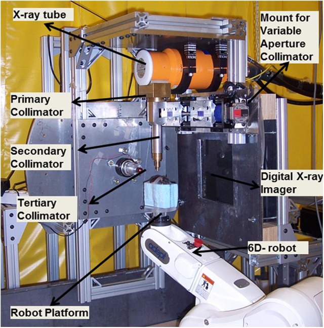
Small animal conformal radiation therapy device (SACRTD) setup for conformal radiation therapy delivery.
Table 1.
Technical Specifications of the SACRTD System.
| X-ray source | GE Seifert X-ray tube Isovolt Titan 225 M2 |
|---|---|
| Model | NDI 225 M metal ceramic dual focal spot |
| Focal spot size | 0.4/3 mm |
| Power | 640/3000 W |
| Inherent filtration | 0.8 mm Be |
| Additional filtration | 0.5 mm Cu |
| Generator | GE Isovolt Titan 225 |
| Target angle | 20° |
| Robot manufacturer | Adept Inc, Livermore, California |
| Robot model | Adept Viper s650 |
| Robot’s overall arm length | 565 mm (270 mm first arm and 295 second arm) |
| Robot’s motion range | J1 ± 170°, J2 = −190°, +45°, J3 = −29°,+256°, J4 = ±190°, J5 = ±120°, J6 = ±360° |
| Robot’s maximum pay load | 5 kg |
| Robot’s positional repeatability | ±0.02 mm in each of X, Y, and Z direction |
| Robot’s drive motor and break | AC servo motors for all joints and breaks for joint J2 and J6 |
| Robot’s controller | Adept Smart controller and Adept T1 pendent |
| Flat panel x-ray detector | Perkin-Elmer, Wiesbaden, Germany |
| X-ray detector model | XRD 0820 CN3 digital x-ray detector |
| X-ray detector size | 20.48 × 20.48 cm |
| Pixel matrix format | 1024 × 1024 |
| Pixel pitch | 0.2 mm |
| Scintillator | CsI (Tl) |
| Maximum frame rate | 7 fps |
Abbreviations: fps, frames per second; SACRTD, small animal conformal radiation therapy device.
Shielding and safety
The SACRTD is kept inside a 1.8 × 1.8 × 1.8 m enclosure. The enclosure walls are made of steel on the outside and 10 lb/ft2 lead blankets (Lance Industries, Washington) of 12.5 mm equivalent thickness in the inner core. The primary, scatter, and leakage shielding and safety requirements are performed based on the National Council on Radiation Protection and Measurements (NCRP) report 49.19,20 The 225 kVp energy setting is generally used for conformal irradiation with the primary beam orientation toward the floor. For cone-beam imaging, the tube is rotated about the gantry and oriented along the horizontal direction toward the digital X-ray imager (60-100 kVp). The NCRP report 49-based calculations required minimum barrier thickness of 14, 6.2, and 3.8 mm of lead for the primary, secondary, and leakage radiation, respectively. The SACRTD system currently uses 25.4 mm (1 in) of lead in the primary beam barrier and 12.5 mm of lead to shield the secondary and leakage radiation. Survey was performed using a calibrated ionization chamber survey meter. The measured dose rates were presented for approval by the radiation safety committee.
Six-axis Viper S650 Robot
The Adept Viper S650 (Adept Inc, Fremont, California) is a flexible and high-precision robot with 6 DOF. Refer to technical specifications of the SACRTD system in Table 1.21 A custom-made plexiglass plate or the “palm” is mounted on the top of the robotic arm providing submillimeter accuracy in positioning. In order to reduce the scatter dose, the animal is placed above a Styrofoam block fastened to the robotic arm. Moreover, depending on the need of each experiment, an animal immobilization or bed can be constructed and adapted as we have done, for example, for rat heart irradiation experiments mentioned in the study Sharma et al.22 The overall operation of the X-ray controller and imaging system is controlled via a visual basic-based graphical user interface.
Conformal radiation delivery system
The 225 kVp X-ray tube is mounted on the custom-made gantry and can be rotated up to 120° about the isocenter, which is at 32.5 cm from the X-ray source. A collimator assembly can be mounted on the window of the X-ray tube with a slot for attaching different-sized collimators at the lower end of the collimating assembly. Beam collimation was achieved by means of a brass primary collimator (2.5 cm long × 0.5 cm diameter), an aluminum secondary collimator (15.5 cm long × 1.9 cm diameter) with interchangeable nozzles providing circular fields of 0.5 and 1 mm in diameter, and rectangular fields of 2 × 2 mm2 and 4 × 4 mm2 at the isocenter. The cone tips, beam profile, and film exposure of the collimators are shown in Figure 2. Two lasers mounted in the wall and the gantry aid in target placement. The position of isocenter is further confirmed by gantry and robotic arm star shot measurements using a film. Figure 3A shows the star shot at different gantry orientations for the 1-mm collimator on a Gafchromic XR-RV2 film (International Specialty Products, New Jersey). The beam intersects within ±0.20 mm at isocenter when the X-ray tube is rotated from the vertical to the horizontal position. Figure 3B illustrates the X-ray beam alignment with respect to the rotational axis of the robot on a Gafchromic XR-RV2 film for the 0.5-mm-diameter field. The robot rotational axis can be positioned within ±0.20 mm of the X-ray central axis. This small offset can be compensated via the robot calibration. Figure 3C displays the microbeam 10-mm square grid pattern with rows separated by 1 mm on a Gafchromic XR-RV2 film. The surface plot of relative optical density (OD) distribution of the corresponding grid patterns is also shown. The result shows highly conformal irradiation possible through correctly programming the robot.
Figure 2.

The cone tips, beam profile, and film exposure for 0.5 mm and 1 mm diameter and 2 × 2 mm2 and 4 × 4 mm2 collimators at isocenter.
Figure 3.
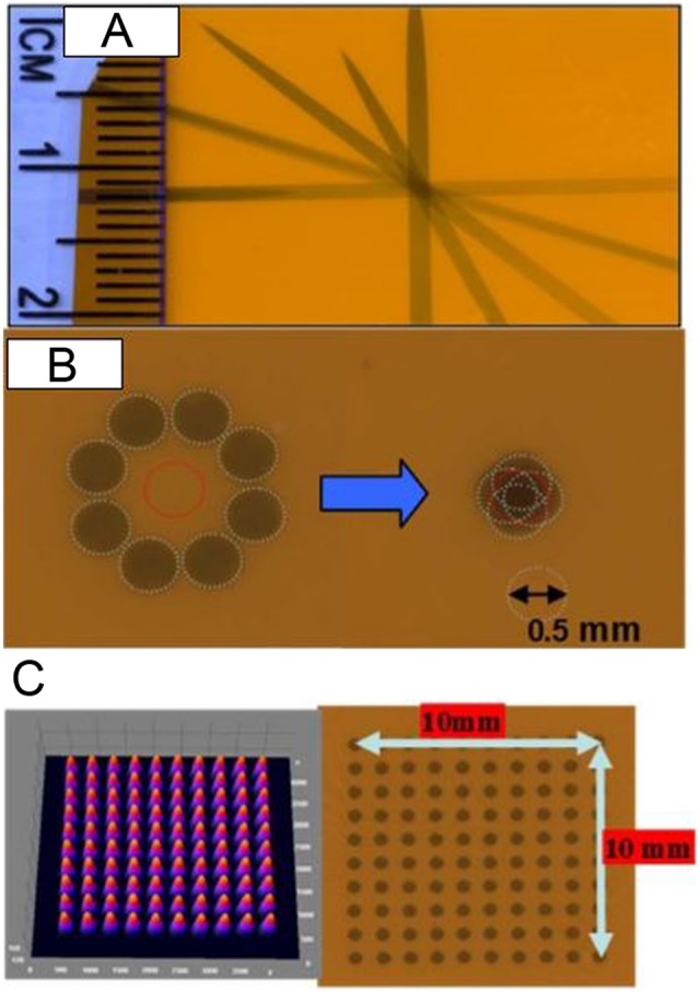
A, Gantry star shot image when the X-ray tube is rotated from the vertical to the horizontal position using 1-mm collimator. B, Image illustrates the 0.5-mm-diameter X-ray beam alignment with respect to the robot rotation axis. The beam intersects within ±0.20 mm at isocenter. C, Image shows microbeam square grid pattern from 0.5-mm-diameter collimator at isocenter (100 kV, 6 mA with 1 minute exposure) measured using Gafchromic film placed at 1 cm below isocenter. For 10 × 10 mm2 spatially fractionated radiation therapy (GRID), the rows are separated by 1 mm. The surface plot of relative optical density distribution of corresponding grid patterns is also shown.
Variable aperture collimator
A custom-made variable aperture that can be mounted at the end of the X-ray window was designed in-house. The system has 2 interlocking brass block structures (2.5-in thick) mounted on a uniaxial bislide in a linear stage, as shown in Figure 4A. The variable aperture system is computer controlled, is mounted on a linear stage, and can either completely block the beam or can have opening up to 4 × 4 mm2 at 8 cm below the X-ray tube opening or up to 20 × 20 mm2 at the beam isocenter (Figure 4B). The setup allows the source to object distance to be as low as 20 cm by moving the robotic arm toward the X-ray tube, enabling higher dose delivery over shorter periods of time.
Figure 4.
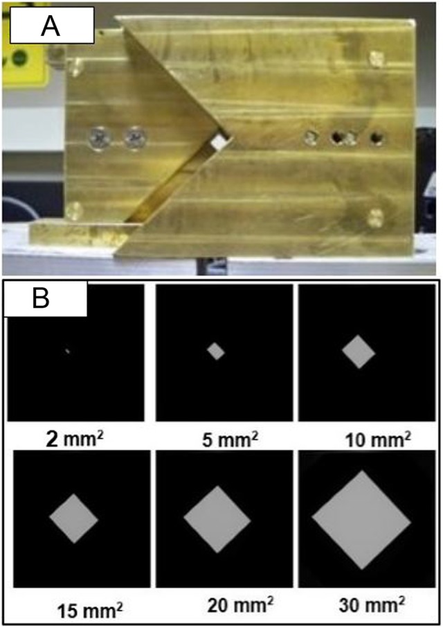
A, Variable apertures collimation system mountable at the open end of the X-ray tube, which can produce field size up to 20 × 20 mm2 at isocenter. B, Images of various field sizes ranging from 2 × 2 mm2 to 30 × 30 mm2 recorded at digital imager.
Animal cone-beam computed tomography system
The SACRTD has high-resolution digital X-ray imaging capability. Digital X-ray images are acquired by the Perkin Elmer XRD 0820 CN3 digital X-Ray detector (PerkinElmer, Santa Clara, CA), which has 8″ amorphous flat panel silicon (a-Si) sensors, and a 2-dimensional (2D) photodiode array converts the detected X-rays into light using a CsI (TI) scintillator.23 The needle-like structures of the CsI (TI) scintillators are coupled to an array of photodiodes on the a-Si plate. Sixteen-bit images were acquired at 65 kVp, 1 mA using the small focal spot of 0.4 mm at a frame rate of 7.5 frames per second (fps) at 200 μm pixel and 15 fps at 400 μm pixel (2 × 2 binning) resolution. The image acquisition configuration is shown in Figure 5. The default image magnification factor of 1.7 could be changed with other source-to-detector configurations, which makes SACRTD well suited to acquire high-resolution magnified radiographs of a small target. An in-house MATLAB (Mathworks, Natick, Massachusetts)-based software was developed using Feldkamp-Davis-Kress filtered back projection algorithm to study the image quality parameters.
Figure 5.
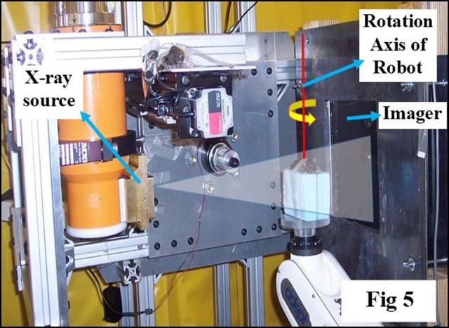
Picture illustrating setup for cone-beam computed tomography (CBCT) imaging with horizontally oriented X-ray source, object immobilized on the robotic arm, and imaging detector at a fixed distance from the source. A software tool controls the robot motion, the X-ray activation, and data acquisition by the imager.
Dosimetry
For calibration, an open-field (20 × 20 mm2 at isocenter) in-air dose at isocenter was measured with a calibrated PTW Farmer chamber (0.015 cm3) (PTW, Freiberg, Germany) and CNMC electrometer (CNMC Inc., Nashville, TN), with the tube set to 225 kV and 13 mA current with the large focus (3 mm—note that the tube has an inherent filtration of 0.5 mm of copper). Similar measurements were done at depths of 1 and 2 cm in solid water, and the delivered dose was calculated by following the TG-61 protocol.
Gafchromic EBT-2 film (International Specialty Products)-based analysis was carried out through a modified version of the process outlined in the study by Devic et al.24 Ten preirradiation dark scans (scan without any film and external light) and 5 preirradiation scans were acquired in 4 × 4 cm2 film and scanned in an Epson V700 flat-bed scanner (Epson Perfection V700 Photo) (Epson, Long Beach, CA). Postirradiation scans were performed 24 hours after film irradiations, with the films placed in the same position and orientation on the scanner. Films were scanned in 16-bit gray, at 150 dpi resolution, and saved in tiff format. In-house software written in MATLAB was used to acquire the net OD distributions and hence calculate doses delivered to the film. In addition, a calibration curve for Gafchromic EBT2 film was drawn by exposing it in 6-MV X-rays beams using a Varian Clinac 21EX (Varian Medical Systems, Palo Alto, CA).
Depth-dose variation in solid water was measured for all nozzle collimators using a stack of 7 cm × 7 cm × 3.1 mm solid water phantoms, with the 5 × 5 cm2 pieces of Gafchromic EBT-2 films placed at different depths and irradiated for 4 minutes.
Animal Irradiation Studies and CBCT Imaging Using SACRTD
Pilot study with spatially fractionated radiotherapy
GRID therapy, also known as spatially fractionated radiation therapy, is an effective technique to treat large tumors by significantly reducing the overall clonogenic fraction prior to conventional fractionated radiation therapy. Experiments were performed to observe some of the molecular changes occurring after GRID in C57 mice implanted with B16 murine melanoma tumors. Tumors were grown by inoculating 2 to 4 × 10⁵ B16 melanoma cells subcutaneously approximately 10 days before irradiation. Animals were anesthetized with a ketamine/xylazine cocktail, and each target point (bearing ∼1 cm3 tumors) was irradiated sequentially by the 1-mm-diameter and 2 × 2 mm2 square collimators. The honeycomb patterns were created by programming the robot to move the beam assembly in a step-and-shoot fashion. Each target point was irradiated at 225 kV and 13 mA to give 10 Gy at 1 cm deep. Tumors were collected at 1 hour post-GRID exposure, flash frozen in liquid nitrogen, and processed for immunohistochemical localization of H2AX foci.
Therapeutic study in rat MAT B III orthotropic breast cancer
In terms of GRID therapy research, we have gone on to characterize the relevant bystander effects caused by GRID radiation as well GRID-induced changes in radioresponsiveness of the tumor to subsequent radiation therapy alone or in combination with other therapeutic agents.25 With the hypothesis that GRID may induce antitumor effects above and beyond direct radiation-induced cell killing, we have also recently studied the response of a rat breast tumor model to GRID alone and combined with thermal ablation. The goal was to understand whether the addition of GRID to ablation may improve control of the tumor, possibly via immune activation and bystander-related effects. Using the SACRTD, we were able to reliably expose the relatively large rat tumors grown in the mammary fat pad of the lower abdomen to a consistent GRID dose.
MAT B III tumors were grown in the lower abdominal mammary fat pads in Fischer rats by inoculation. Upon reaching a volume of approximately 1 cm3, they were randomized into the following treatment groups each with n = 15 rats: control (untreated), GRID therapy at 20 Gy alone, thermal ablation, or thermal ablation followed by GRID 72 hours postablation. The GRID was applied using a newly designed collimator in scale with the clinically used block. Thermal ablation was performed by inserting the conductive interstitial thermal therapy probe at the center of tumor. The tumor growth was evaluated by measuring tumor diameter and estimating volume every day postradiation.
Imaging study with SACRTD
A series of radiographic images were recorded of a phantom and rat (65 kV, 5 mA) in CBCT mode positioned using the 6 DOF robotic arm to study image reconstruction by SACRTD.
Image-guided radiation-induced heart irradiation studies
In radiotherapy treatment of thoracic and chest wall tumors, a portion of the heart may be included in the radiation field, which may result in radiation-induced heart disease (RIHD) several years after irradiation. We developed a model to study conformal local heart irradiation in rats using SACRTD. Adult male Sprague Dawley rats were exposed to localized heart irradiation dose of 18 Gy using SACRTD system with secondary aluminum collimator that gives 20-mm diameter beam at isocenter. For this purpose, rats were anesthetized with isoflurane and placed in a custom-made vertical rat holder. The heart was localized based on 2D imaging and exposed to 3 fields of 6 Gy each, 1 anterior–posterior field and 2 lateral fields. Hearts and lungs were isolated at time points from 2 hours to 4 days after irradiation, fixed in formalin, and processed. Immunohistochemistry was performed to show γH2Ax, a marker for DNA damage caused by radiation-induced oxidative stress, and nitrotyrosine, a marker for protein nitration caused by nitrosative stress.
Results and Discussion
The conformal irradiation of 3D targets and volumetric imaging capability is extremely crucial for more sophisticated approaches in the study of biology at the preclinical level. The SACRTD device fulfills these requirements and has proven to be a valuable component of our radiation research program.
Shielding and Safety
The shielding was checked for integrity and stability. Survey was performed using a calibrated ionization chamber survey meter using the following specifications: largest collimator opening with gantry pointing toward the survey meter, X-ray source operating at highest voltage, and current setting using the largest focal spot. The dose rate at 1 m from the tube is less than 13 Sv/h, with less than 10 mSv/h of leakage radiation. When attached, the brass collimator could reduce the primary, secondary, and leakage radiation. The SACRTD is thus shielded and safe to use as required by NCRP report 49, and the system is approved for irradiation studies by our institutional radiation safety committee.
Dosimetry Considerations
The in-air dose rate for an open 20 × 20 cm2 field at isocenter was measured to be 3.94 Gy/min using a calibrated PTW Farmer chamber and CNMC electrometer. Similarly, the dose rates measured at 1 and 2 cm depth in solid water were 2.921 and 2.626 Gy/min, respectively.
A calibration curve for the 4 × 4 mm2 collimator was performed, and data were compared with the clinical beam (Figure 6A). The curve of best fit between OD and dose delivery was determined to be a third-order polynomial. The OD was measured in the densitometer (X-Rite model 30) (X-Rite, Grand Rapids, MI) using a densitometer resolution of 1 mm2. The doses from smaller collimators were then calculated by relative film dosimetry using Gafchromic EBT-2 films and the calibration curve.
Figure 6.

A, The calibration curve for dose delivered on the Gafchromic EBT-2 film exposed to clinical 6 MV X-ray beam using cubic polynomial fit, with error bar representing uncertainty in film measurement. Inset shows the similar plot for 4-mm collimator. B, Dose rate variation with depth in a solid water setup at 32.5 cm source to surface distance (SSD) for 0.5 and 1 mm diameter and 2 × 2 mm2 and 4 × 4 mm2 collimators. C, Relative beam profiles at 1 cm depth in a solid water setup at 32.5 cm SSD for 0.5 and 1 mm diameter and 2 × 2 mm2 and 4 × 4 mm2 collimators (225 kVp, 13 mA photon beam). D, Cross-beam profiles at depths of 0, 18.6, and 37.2 mm for a 0.5-mm-diameter collimator. E, Normalized beam profiles for 2 × 2 mm2 collimator at depths of 0, 18.6, and 37.2 mm.
Dose rate as a function of depth is shown in Figure 6B for a solid water setup at 32.5 cm source to surface distance using the 225 kVp source operated at 13 mA and large focus. The decrease in dose rate for the small-sized collimators may be the fact that at very small field sizes, the beam becomes comparable to the size of the penumbra, and therefore, it might limit dose rate, and highly accurate relative film dosimetry is needed. The dose rate variation in collimator size is comparable to the dose rate reported by Wong et al on similar types of collimators and system setup.12
The relative beam profiles for all the collimators were studied at 1 cm depth in solid water as illustrated in Figure 6C. Cross-beam profile plot of the 0.5-mm-diameter collimator at different depths is shown in Figure 6D. In the normalized beam profile of the 2 × 2 mm2 collimator plotted in Figure 6E, notice the beam divergence with depth. The full-width half-maximum was calculated for all the beam sizes at isocenter (top of solid water), 18.6 and 37.2 mm depth in solid water, and is tabulated in Table 2. The uncertainty in the measurement is ∼±3%. The 80% to 20% penumbra is 0.2 to 0.3 mm for the 1-mm-diameter beam and 0.5 to 0.6 mm for the 4 × 4 mm2 beam over the measured depths.
Table 2.
Gafchromic EBT-2 Film Measurement of FWHM and 80% to 20% Penumbra at Different Depths for Various Collimators.
| Collimator | At Isocenter | At 18.6 mm Depth | At 37.2 mm Depth | |
|---|---|---|---|---|
| 0.5 mm diameter | FWHM (mm) | 0.47 | 0.54 | 0.61 |
| Penumbra (mm) | 0.2 ± 0.1 | 0.3 ± 0.1 | 0.3 ± 0.1 | |
| 1 mm diameter | FWHM (mm) | 1.14 | 1.18 | 1.2 |
| Penumbra (mm) | 0.3 ± 0.1 | 0.4 ± 0.1 | 0.5 ± 0.1 | |
| 2 × 2 mm2 | FWHM (mm) | 2.46 | 2.57 | 2.63 |
| Penumbra (mm) | 0.5 ± 0.1 | 0.58 ± 0.1 | 0.5 ± 0.1 | |
| 4 × 4 mm2 | FWHM (mm) | 4.48 | 4.81 | 5.01 |
| Penumbra (mm) | 0.5 ± 0.1 | 0.5 ± 0.1 | 0.6 ± 0.1 |
Abbreviation: FWHM, full-width half-maximum.
GRID Therapy Experiments
GRID therapy involves a single large fraction of ∼15 to 20 Gy in a honeycomb pattern using 1-mm-diameter and 2 × 2 mm2 collimator and requires localization technique accurate to within submillimeter, which is available with SACTRD system.25 We observed some of the molecular changes occurring after GRID therapy in C57 mice implanted with B16 murine melanoma tumors. Figure 7A displays a hexagonal pattern recorded at isocenter using 7 beams of 1 mm diameter separated by 2-mm center-to-center and a checkerboard pattern, with 6 squares of 2 × 2 mm2 with 2.5-mm separation. The surface plots of the relative OD distributions are also shown. Figure 7B shows an overlay image (×4 magnification) of B16 murine melanoma stained with γ-H2AX (Bethyl Laboratories) to identify radiation-induced DNA damage and counterstained with 46′-diamidino-2-phenylindole-2 HCl staining for nuclear identification. The sharp bright region shows γ-H2AX staining. Notice the size of the bright region is approximately 1 mm diameter, consistent with the diameter of the 1-mm beam used for irradiation. The inset picture in Figure 7B shows mice with an implanted tumor on the left hind leg. Figure 7C features ×20 magnification image of Figure 7B, showing γ-H2AX nuclear foci consistent with radiation-induced DNA damage at those sites.
Figure 7.

A, Hexagonal spatially fractionated radiation therapy (GRID) pattern with 7 beams of 1 mm diameter separated by 2-mm center-to-center and a checkerboard GRID pattern with 6 squares of 2 × 2 mm2 collimators separated by 2.5 mm center-to-center. Exit beam pattern measured with Gafchromic XR-RV2 film by programming the robot to move the beam assembly in a step-and-shoot fashion. The corresponding surface plot is shown. B, Overlay image (×4) of BI6 murine melanoma stained with γ-H2AX (Bethyl Laboratories) to identify radiation-induced DNA strand breaks counterstained with 46′-diamidino-2-phenylindole-2 HCl (DAPI) staining for nuclear identification. The sharp bright region shows γ-H2AX staining, and the size of the bright region is approximately ∼1 mm diameter consistent with the diameter of the 1 mm beam used for irradiation. Insert, Mice with implanted tumor on the leg. C, Shows ×20 magnification of Figure 7B, showing γ-H2AX nuclear foci consistent with radiation-induced DNA breaks. D, Plot shows the growth of B16 tumors in rear limb of C57 mice after 10 Gy GRID alone or followed by 5 days of treatment with the antiangiogenic peptide anginex at 20 mg/kg intraperitoneally (IP). Each group contained 3 mice, and bars indicate 1 standard error of the mean volume per group.
When B16 murine melanoma tumors were treated with GRID, cell survival was assessed with the in vivo/in vitro excision assay26 and there was an expected decrease in clonogenicity. There was nearly a 50% decrease in tumor cell ability to remain clonogenic after GRID treatment, which might be predicted as approximately half of the tumor was exposed to a cytotoxic dose. This goes to show that tumors can be accurately irradiated by a variety of patterns, and the cellular kill by GRID is significant.
There may be more to the effect of GRID therapy than a linear cell killing proportional to the total fraction of area irradiated. We have also studied the effect of targeted therapeutics on tumors after GRID treatment in a pilot study to understand possible ways to improve GRID in clinic. The growth of B16 tumors in rear limb of C57 mice after 10 Gy GRID alone or followed by 5 days of treatment with the antiangiogenic peptide anginex at 20 mg/kg intraperitoneally was evaluated. Figure 7D shows the mean tumor volume progression between the control group and that treated with GRID alone and in combination with anginex. Each group contained 3 mice, and error bars indicate 1 standard error (SE) of the mean volume per group. Previous extensive studies in the development of the anginex peptide have demonstrated only mild enhancement in tumor growth delay, and therefore, we did not add an anginex-alone group to the current study.27–29 Antiangiogenic agents may exacerbate the cell kill effect of GRID suggesting the importance of vascular response to spatial fractionation. The results demonstrate the high degree of precision possible with the SACRTD and its potential for designing in vivo radiobiological studies requiring highly conformal and precise radiation dose patterns.
Therapeutic Study in Rat MAT B III Orthotropic Breast Cancer
In the therapeutic study involving MAT B III orthotropic breast tumor control in rats (n = 15 per group), percentage regression in tumor size is illustrated in Figure 8. Overall, there was a significant improvement in tumor control when GRID was applied after ablation, which is a useful result for our translational goal to combine thermal medicine and radiation therapy. One advantage of using GRID therapy with another regimen such as thermal ablation is that a single prescription dose may be sufficient to improve outcomes without radiotherapy boost. Conversely, if the single fraction of ablation and GRID are deemed to be insufficient when translated to humans, lack of normal tissue complications with the addition of GRID to a standard fractionation regimen allows flexibility in the treatment course for each patient.
Figure 8.
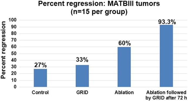
Percentage regression in rat MAT B III orthotropic breast cancer in the 4 groups (n = 15 in each group).
Cone-Beam Computed Tomography Imaging
A set of 360 projection digital radiographic image of a mouse and physical phantoms were acquired (1024 × 1024 at 200 µm resolution) in 1 CBCT image. The CBCT images were reconstructed and exported into standard Digital Imaging and Communications in Medicine format. Currently, the image acquisition takes approximately 2 minutes and reconstruction can be performed within 5 minutes for 360 projection images (cropped and reduced to 512 × 512 pixel size and 200 µm resolution), which can be drastically improved with a faster computer. The resulting reconstruction matrix for the mouse image was 309 × 154 × 76 voxels with spacing of 0.3 × 0.3 × 0.3 mm3. The reconstructed images display the soft organs/muscle, lungs, and bone structure (Figure 9). Similarly, 360 projection images of a tomotherapy resolution phantom were acquired, cropped, downsampled to 301 × 301 pixel size (resolution = 200 µm), and reconstructed (141 × 141 × 199 voxels) with spacing of 0.3 × 0.3 × 0.3 mm3. The reconstructed image clearly displays the smaller holes as small as 0.65 mm (Figure 10A). The amount of radiation dose delivered to acquire 360 projection is less than <0.5 cGy for 360° rotation, which is much less than that for a micro-CT shown in Figure 10B for comparison.
Figure 9.
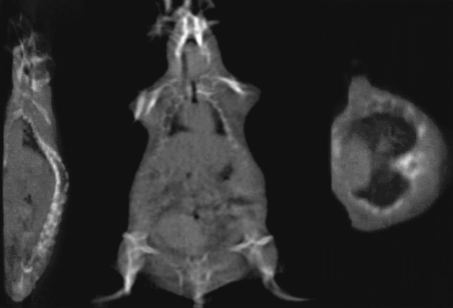
The cone-beam computed tomography (CBCT) reconstructed slices of sagittal, coronal, and axial images of rat. Three hundred sixty projection images were cropped and downsampled to 512 × 512 pixels at 400 μm resolution. The resulting reconstructed matrix was 309 × 154 × 76 voxels with uniform spacing of 0.3 mm in the X, Y, and Z directions.
Figure 10.

A, Cone-beam computed tomography (CBCT) reconstructed images of a tomotherapy resolution phantom from 360 projection images of 301 × 301 pixels at 200 μm resolution. The reconstructed matrix size was 141 × 141 × 199 voxels with uniform spacing of 0.3 mm in the X, Y, and Z directions. B, The microcomputed tomography (CT) of same phantom is also shown for comparison.
Partial Heart Irradiation Studies
Representative image of the immunohistochemical staining of nitrotyrosine in the heart at 6 hours after sham irradiation is shown in Figure 11A, in which minimal nitrotyrosine was detected. Both γH2Ax staining and nitrotyrosine staining were observed throughout the irradiated hearts, indicating that the whole heart was exposed to radiation. γH2Ax was most prominent at 2 hours after irradiation, as DNA repair is known to start immediately after exposure.30–33 Increased nitrotyrosine staining was observed mainly in cardiomyocytes, at all time points after irradiation. Representative image of the immunohistochemical staining of nitrotyrosine at 6 hours after irradiation is shown in Figure 11B and C. Minimal γH2Ax and nitrotyrosine were observed in the lung samples (data not shown), and previous studies revealed no evidence of radiation-induced changes in the lung of animals receiving 21 Gy of heart irradiation.22 Long-term follow-up of animals revealed histopathological manifestations of RIHD, including myocardial degeneration and fibrosis. The results demonstrate that the rat heart irradiation technique using the SACRTD was successful while sparing the surrounding untargeted tissues, making this approach a powerful tool for in vivo radiobiological studies of RIHD.
Figure 11.

Immunohistochemical staining of nitrotyrosine (brown) of the (A) sham-irradiated heart and (B and C) irradiated hearts at 6 hours after irradiation (×40 magnification). Staining was observed at all time points after irradiation, mainly in cardiomyocytes. Minimal nitrotyrosine was detected after sham irradiation.
Conclusions
The experimental results have demonstrated that the SACRTD system can deliver high-dose conformal radiation therapy to a small laboratory animal at the submillimeter scale, while sparing the surrounding normal tissues. Importantly, our system provides the flexibility and option to deliver spatial fractionation (GRID) using fixed collimators or by the precise movement of the robotic arm. These studies are being expanded to allow further understanding and translation of the mechanism by which the GRID technique inhibits tumor progression. In addition, the SACRTD can acquire high spatial resolution radiographic images and reconstruct 3D CBCT images. In summary, the SACRTD system has innumerable potential research applications and is a translational research tool that can be used to study many areas of medicine involving ionizing radiation.
Acknowledgments
The authors would like to acknowledge the assistance from Tommie Carter in proofreading the manuscript and giving valuable feedback.
Abbreviations
- CBCT
cone-beam computed tomography
- CT
computed tomography
- 2D
2-dimensional
- 3D
3-dimensional
- DOF
degrees of freedom
- Fps
frames per second
- GRID
spatially fractionated radiation therapy
- NCRP
National Council on Radiation Protection and Measurements
- OD
optical density
- SACRTD
small animal conformal radiation therapy device
- SARRP
small animal radiation research platform
- SE
standard error
- RIHD
radiation-induced heart disease
Footnotes
Declaration of Conflicting Interests: The author(s) declared no potential conflicts of interest with respect to the research, authorship, and/or publication of this article.
Funding: The author(s) disclosed receipt of the following financial support for the research, authorship, and/or publication of this article: This research was supported by the Arkansas Biosciences Institute (ABI), a grant from the Arkansas Breast Cancer Research Program, the University of Arkansas for Medical Sciences Translational Research Institute (CTSA Grant Award UL1TR000039), and NIH R01 CA148679
References
- 1. Denekamp J. Tumour regression as a guide to prognosis: a study with experimental animals. Br J Radiol. 1977;50(592):271–279. [DOI] [PubMed] [Google Scholar]
- 2. Augustine AD, Gondré-Lewis T, McBride W, Miller L, Pellmar TC, Rockwell S. Animal models for radiation injury, protection and therapy. Radiat Res. 2005;164(1):100–109. [DOI] [PubMed] [Google Scholar]
- 3. DesRosiers C, Mendonca MS, Tyree C, et al. Use of the Leksell gamma knife for localized small field lens irradiation in rodents. Technol Cancer Res Treat. 2003;2(5):449–454. [DOI] [PubMed] [Google Scholar]
- 4. Halperin EC, Sontag MR. Techniques of Experimental Animal Radiotherapy. Lab Anim Sci. 2004;44(5):417–423. [PubMed] [Google Scholar]
- 5. Holdsworth DW, Thornton MM. Micro-CT in small animal and specimen imaging. Trends Biotechnol. 2002;20:S34–S39. [Google Scholar]
- 6. Izaguirre EW, Diao X, Mutic S, et al. MO-E-AUD C-07: modeling small animal micro irradiator orthovoltage sources. AAPM. 2008;35(6):2877. [Google Scholar]
- 7. Jacobs RE, Cherry SR. Complementary emerging techniques: high-resolution PET and MRI. Curr Opin Neurobiol. 2001;11(5):621–629. [DOI] [PubMed] [Google Scholar]
- 8. Matinfar M, Ford E, Iordachita I, Wong J, Kazanzides P. Image-guided small animal radiation research platform: calibration of treatment beam alignment. Phys Med Biol. 2009;54(4):891–905. [DOI] [PMC free article] [PubMed] [Google Scholar]
- 9. Stojadinovic S, Low DA, Vicic M, et al. Progress toward a microradiation therapy small animal conformal irradiator. Med Phys. 2006;33(10):3834–3845. [DOI] [PubMed] [Google Scholar]
- 10. Stojadinovic S, Low DA, Hope AJ, et al. MicroRT—small animal conformal irradiator. Med Phys. 2007;34(12):4706–4716. [DOI] [PubMed] [Google Scholar]
- 11. Graves EE, Zhou H, Chatterjee R, et al. Design and evaluation of a variable aperture collimator for conformal radiotherapy of small animals using a microCT scanner. Med Phys. 2007;34(11):4359–4367. [DOI] [PubMed] [Google Scholar]
- 12. Wong J, Armour E, Kazanzides P, et al. High-Resolution, small animal radiation research platform with X-ray tomographic guidance capabilities. Int J Radiat Oncol Biol Phys. 2008;71(5):1591–1599. [DOI] [PMC free article] [PubMed] [Google Scholar]
- 13. Weersink RA, Ansell S, Wang A, et al. Integration of optical imaging with a small animal irradiator. Med Phys. 2014;41(10):102701. [DOI] [PubMed] [Google Scholar]
- 14. Woo MK, Nordal RA. Commissioning and evaluation of a new commercial small rodent x-ray irradiator. Biomed Imaging Interv J. 2006;2(1):e10. [DOI] [PMC free article] [PubMed] [Google Scholar]
- 15. Lindsay P, Ansell S, Moseley D, Jelveh S, Hill R, Jaffray D. SU-GG-J-70: development of an image-guided conformal small animal irradiation platform. AAPM. 2008;35(6):2695–2695. [Google Scholar]
- 16. Deng H, Kennedy CW, Armour E, et al. The small-animal radiation research platform (SARRP): dosimetry of a focused lens system. Phys Med Biol. 2007;52(10):2729. [DOI] [PubMed] [Google Scholar]
- 17. Sharma S, Moros E, Corry P. SU-GG-J-160: radiation enclosure shielding calculations for a laboratory-based small animal conformal radiation therapy device. AAPM. 2008;35(6):2716. [Google Scholar]
- 18. Sharma S, Moros E, Corry P. SU-GG-J-170: small animal conformal radiation therapy device. AAPM. 2008;35:2718. [DOI] [PMC free article] [PubMed] [Google Scholar]
- 19. National Council on Radiation Protection and Measurements (NCRP). “Structural shielding design and evaluation for medical use of x rays and gamma rays of energies up to 10 MeV”. NCRP Report No. 49 Bethesda, MD: NCRP; 1976. [Google Scholar]
- 20. Simpkin DJ. Evaluation of NCRP Report No. 49 assumptions on workloads and use factors in diagnostic radiology facilities. Med Phys. 1996;23(4):577–584. [DOI] [PubMed] [Google Scholar]
- 21. Adept. Viper S650/S850 Robot User’s Guide. Livermore, CA: Adept Technology Inc; 2006. [Google Scholar]
- 22. Sharma S, Moros EG, Boerma M, et al. A novel technique for image-guided local heart irradiation in the rat. Technol Cancer Res Treat. 2014;13(6):593–603. [DOI] [PMC free article] [PubMed] [Google Scholar]
- 23. XRD 0820AN. Reference Manual. Santa Clara, CA: Perkin Elmer Inc. [Google Scholar]
- 24. Devic S, Seuntjens J, Sham E, et al. Precise radiochromic film dosimetry using a flat-bed document scanner. Med Phys. 2005;32(7):2245–2253. [DOI] [PubMed] [Google Scholar]
- 25. Asur RS, Sharma S, Chang CW, et al. Spatially fractionated radiation induces cytotoxicity and changes in gene expression in bystander and radiation adjacent murine carcinoma cells. Radiat Res. 2012;177(6):751–765. [DOI] [PMC free article] [PubMed] [Google Scholar]
- 26. Song CW, Lee YJ, Griffin RJ, et al. Indirect tumor cell death after high-dose hypofractionated irradiation: implications for stereotactic body radiation therapy and stereotactic radiation surgery. Int J Radiat Oncol Biol Phys. 2015;93(1):166–172. [DOI] [PMC free article] [PubMed] [Google Scholar]
- 27. Dings RP, Williams BW, Song CW, Griffioen AW, Mayo KH, Griffin RJ. Anginex synergizes with radiation therapy to inhibit tumor growth by radiosensitizing endothelial cells. Int J Cancer. 2005;115(2):312–319. [DOI] [PubMed] [Google Scholar]
- 28. Dings RP, Loren M, Heun H, et al. Scheduling of radiation with angiogenesis inhibitors anginex and Avastin improves therapeutic outcome via vessel normalization. Clin Cancer Res. 2007;13(11):3395–3402. [DOI] [PMC free article] [PubMed] [Google Scholar]
- 29. Amano M, Suzuki M, Andoh S, et al. Antiangiogenesis therapy using a novel angiogenesis inhibitor, anginex, following radiation causes tumor growth delay. Int J Clin Oncol. 2007;12(1):42–47. [DOI] [PubMed] [Google Scholar]
- 30. Sharma S, Moros EG, Boerma M, et al. A novel technique for image-guided local heart irradiation in the rat. TCRT Express. 2013;13(6):e600256. [DOI] [PMC free article] [PubMed] [Google Scholar]
- 31. Sridharan V, Sharma SK, Moros EG, et al. Effects of radiation on the epidermal growth factor receptor pathway in the heart. Int J Radiat Biol. 2013;89:539–547. [DOI] [PMC free article] [PubMed] [Google Scholar]
- 32. Sridharan V, Tripathi P, Sharma S, et al. Effects of late administration of pentoxifylline and tocotrienols in an image-guided rat model of localized heart irradiation. PLoS One. 2013;8(7):e68762. [DOI] [PMC free article] [PubMed] [Google Scholar]
- 33. Sridharan V, Tripathi P, Sharma SK, et al. Cardiac inflammation after local irradiation is influenced by the kallikrein-kinin system. Cancer Res. 2012;72(19):4984–4992. [DOI] [PMC free article] [PubMed] [Google Scholar]