

Abstract
Background
To date a variety of teleoperated surgical robotic systems have been developed to improve a surgeons ability to perform demanding single-port procedures. However typical large systems are bulky, expensive, and afford limited angular motion, while smaller designs suffer complications arising from limited motion range, speed, and force generation. This work was to develop and validate a simple, compact, low cost single site teleoperated laparoendoscopic surgical robotic system, with demonstrated capability to carry out basic surgical procedures.
Methods
This system builds upon previous work done at the University of Hawaii at Manoa and includes instrument and endoscope manipulators as well as compact articulated instruments designed to overcome single incision geometry complications. A robotic endoscope holder was used for the base, with an added support frame for teleoperated manipulators and instruments fabricated mostly from 3D printed parts. Kinematics and control methods were formulated for the novel manipulator configuration.
Results
Trajectory following results from an optical motion tracker and sample task performance results are presented.
Conclusions
Results indicate that the system has successfully met the goal of basic surgical functionality while minimizing physical size, complexity, and cost.
Introduction
Laparoscopic surgery or minimally invasive surgery (MIS) has revolutionized traditional invasive surgical procedures and in recent years has become an inevitable convention in operating rooms world-wide. Traditional MIS is performed by passing multiple instruments and an endoscope through several small keyhole incisions in the patient body. The popularity of the technique stems from reduced patient trauma and subsequent recovery time realized with the use of smaller incisions [1]. Although minimally invasive surgery is extremely beneficial to patients, the indirect access to the surgical site hampers the surgeons dexterity, vision, and tactile perception.
With the growing prevalence of MIS procedures, a focal point in the continued refinement of the technique has been the pursuit of further reductions in invasiveness. One approach has been a reduction in the number of the incisions. Single-port laparoscopy (SPL) [2, 3] with only one incision and natural orifice transluminal endoscopic surgery (NOTES) [4, 5] with no incision are two maturing techniques in this space. In NOTES procedures the surgical instruments are initially passed through a natural orifice such as the anus or throat and reach the surgical site via small internal incisions within the abdominal cavity. NOTES has many advantages over conventional laparoscopic surgeries including the lack of external scarring, reduction in abdominal wall pain, and reduced risk of external infection [6]. Despite the demonstrated patient benefits widespread adoption of NOTES has been restricted by technical limitations [7, 8, 9].
Single-Port Laparoscopy (SPL) has become the more feasible and utilized alternative to traditional MIS. SPL is performed by inserting a disposable multi-functional trocar through an incision into the abdomen and passing all of the surgical instruments and optics through this single incision. By reducing the number of operative incisions SPL acts as a bridge between a totally scarless surgical paradigm and conventional multi-port laparoscopy. The advantages of SPL are similar to those found with NOTES [10, 11]. While feasible there are challenges associated with performing SPL procedures. The primary limitation is the physical burden imposed on the surgical team by passing multiple instruments and an endoscope through a single incision in close physical proximity. Other considerable complications are instrument crowding, internal and external conflicts of equipment, and the loss of the instrument triangulation within the operative field [12, 13].
Emerging robotics technologies have the potential to address many of the physical and sensory limitations associated with MIS. Many robotic surgical systems [14, 15, 16, 17, 18] have been designed and developed to perform traditional, multiple incision MIS. The da Vinci surgical platform [19] in particular has successfully gained popularity amongst surgeons due to novel characteristics such as 3D optics, intuitive tele-manipulation, improved dexterity, and motion scaling [20]. However adapting the existing, standard MIS robotic systems for use in SPL procedures introduces considerable challenges [21]. The daVinci system address the SPL limitations via modified instruments and specialized trocar [22, 13, 23] and has shown the potential for robotic assistance in these procedures. Unfortunately problems such as non-specialized hardware and software have limited the use of the da Vinci platform in SPL [13]. Consequently a robotic platform designed specifically for SPL is a potential solution to alleviate the limitations of both modified multi-port robotic surgical systems (in SPL) and manual single-site surgeries [21].
Although a number of platforms have been developed to address the limitations of manual SPA surgery there are functional challenges associated with each of the prominent, existing design approaches. Larger systems equipped for single port operation such as the Intuitive Surgical da Vinci [24] are bulky, expensive, and afford limited angular motion.
Another general approach to robotic SPA surgery is to use a device which enters the body as a single shaft which can split into multiple branches inside the body to achieve the needed separation and triangulation between independent end effectors at the operative site. Titan Medical's IREP system from Xu, Simaan, et al [25, 26], the PLAS system from Cheon et al [27], and the SAIT system from Roh et al [28] adopt this approach. Other similar small designs include the miniature system from Wortman et al [29], the SPRINT system [30], the highly versatile system from Salman Can et al [31] and the internal manipulator system of Won-Ho et al [32]. Such small devices typically suffer complications arising from combinations of limited translation, speed, and force generation.
The single-incision surgical robot system of Choi et al [33] uses a similar approach to our own in that multiple shafts are inserted and cross one another at the single incision site. The construction of this system is significantly more complex however.
By addressing these functional deficiencies, the simple, compact, modular, 3D-printable teleoperated surgical system presented in this paper provides advantages in portability, cost, size and ease of use. The stated advantages make the presented system a more viable assistive robotic option for a broader segment of the global medical community thereby potentially increasing the number of surgeons operating with robotic assistance and improving the rates of positive patient outcomes [34, 35].
The system configuration, its forward and inverse kinematics, and control methods are described in the following sections.
Materials and Methods
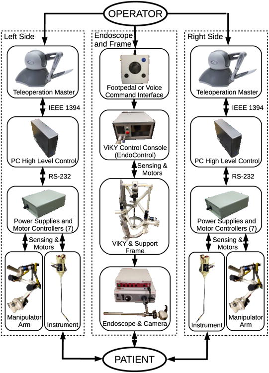
The complete teleoperated system is shown in Fig. 1. This photo includes the system base, its support frame with cross brace, a rigid endoscope with its support arm in the center, and motorized manipulators on either side holding robotic minimally invasive surgical instruments with their shafts passing through a single common insertion point with the endoscope shaft. A schematic block diagram of all the the subsystem components of the teleoperated surgical robot system and their interconnections is shown in Fig. 2, including master and slave devices for the left and right instruments, their manipulators, controllers and power supplies, and the endoscope with its holder and positioning frame.
Figure 1. Complete teleoperated robot system, including ViKY base with endoscope, additional support frame, instrument manipulators and robotic instruments.
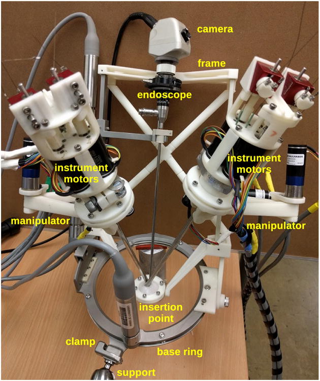
Figure 2. Subsystems and interconnections in single-port teleoperated robotic surgery system.
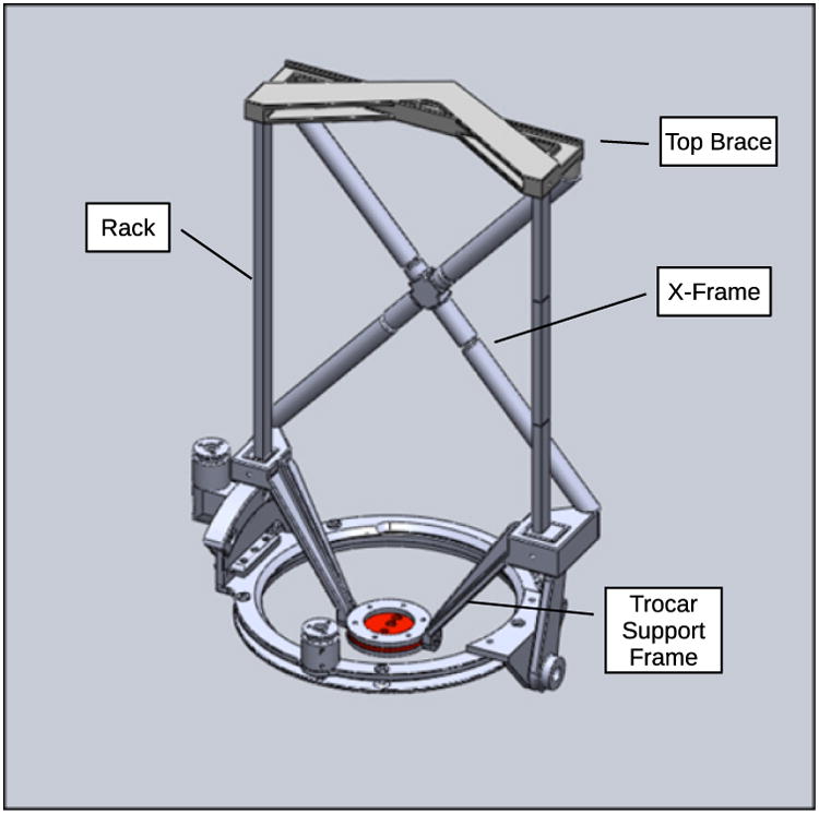
Both instrument manipulators and the endoscope support arm are attached to the support frame, which has stainless steel toothed gear racks on either side for linear actuation and a 3D-printed acrylonitrile butadiene styrene (ABS) cross-brace structure between them for rigidity. A ViKY XL endoscope manipulator from EndoControl Inc. [36] is used as the base of the system and controls the rotation and inclination angles for the support frame of the entire robotic system as well as the insertion depth of the endoscope. The ViKY endoscope manipulator includes voice recognition and pedal motion command interfaces. The design of the system support frame with the ViKY endoscope base is shown in Fig. 3.
Figure 3. Added support frame assembled onto ViKY XL endoscope positioner.
This system configuration is similar to our previous system [37], however in that previous system the endoscope manipulator and each instrument manipulator were separate, each with its own base and incision point, whereas the currently described system incorporates a endoscope holder and two instrument manipulators into a single frame and base so that the three shafts may be inserted through a single incision. The lightweight and compact design of the robotic system enhances safety as the mass of the moving parts is sufficiently low that motors of 25 Watts or less may be used for actuation and the forces and torques required for operation are unlikely to cause significant damage to bodily tissues in the event of a collision. Furthermore, the modular design is a safety feature as any malfunctioning components of the system can be quickly and easily replaced by hand, or teleoperated instruments exchanged for manual instruments at any time.
Surgical Robot Configuration
Because the instrument manipulators and the endoscope are mounted on a single movable frame, the teleoperated instrument motions always remain aligned with the endoscope video image seen by the operator as the endoscope is moved to view different areas inside the body. This novel feature of the system simplifies setup and operation, as compared to teleoperation systems in which the manipulator coordinate frames do not remain aligned to the camera visual frame and must be registered individually when setting up the system. The possibility of collisions between the multiple shafts inside the body during operation is also greatly reduced, as the endoscope frame can move all three shafts together as a single unit.
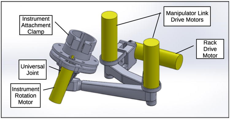
Each instrument manipulator contains three motorized joints which position the exterior end of its surgical instrument, a passive universal gimbal joint which allows the shaft of the instrument to pass through the fixed insertion point as the end of the instrument is moved, and a motor to rotate the instrument about its own shaft axis. Brushless DC gearmotors are attached directly to each actuated joint, with the exception of the rotation of the instrument shaft, which uses 3D printed spur gears between the instrument and gearmotor shafts. The first joint in each manipulator consists of a rack and pinion drive which moves the clamped end of the instrument parallel to the endoscope shaft. This first prismatic joint is followed by two rotational joints and links in series which move the instrument end in the plane perpendicular to the translation direction of the first joint. The three-dimensional motion of the exterior end of the instrument, combined with the passive gimbal joint and the constraint on the instrument shaft to pass through the fixed incision point, produces corresponding three-dimensional teleoperated motion of the instrument tip and end effector inside the body of the patient. The design of one of the two instrument manipulators is shown in Fig. 4.
Figure 4. CAD model of assembled left manipulator arm.
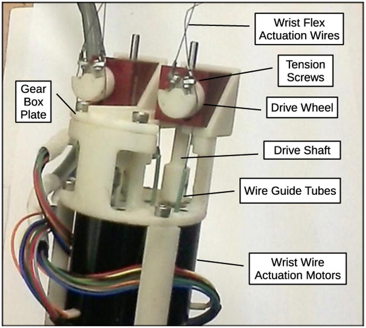
Robotic instruments are attached to the end of each manipulator arm using a simple finger-operated circular clamp mechanism, allowing instruments to be inserted and removed easily during surgical procedures and to be exchanged quickly, from a gripping to a cutting instrument for example. Each instrument has a motorized end effector with jaws for gripping or cutting, and a motorized wrist between the end effector and the instrument shaft which can bend up to 90 degrees in any direction. The end effector and wrist are driven by three brushless DC motors located at the external top end of the instrument and the actuation forces are transmitted by tensioned Nitinol wires passing through the shaft of the instrument. The actuation mechanisms for the robotic instruments are shown in Fig. 5.
Figure 5. Instrument wrist and gripper actuation mechanisms on exterior end of robotic instrument.
The end effector mechanisms are adapted from standard manual minimally invasive surgical instruments. The wrist mechanism is made up of stacked layers of plastic spheres and rings held in place by eight wires threaded through holes in the rings to form a flexible spine structure. Four of the wires are actuated in antagonistic pairs to bend the wrist in two perpendicular directions, and the remaining four wires stabilize the structure and increase its torsional stiffness. This type of flexible spine wrist was first developed by Van Meer [38] and was also used in [37].
The two instruments and the endoscope shaft all cross at a single insertion port to realize a single-site surgical robot system. Due to the divergence of the shafts inside the body of the patient, the instrument shafts are bent near their tips so that the instrument end effectors can reconverge at the operative site. An endoscope with an angled tip improves visibility by providing a view from above the instrument tips rather than in between the two instrument shafts. The right and left side teleoperation masters are switched relative to the external manipulators to place the crossed instruments in correct correspondence as seen in the endoscope image.
Control of the surgical robot is accomplished using both the forward and inverse surgical robot system kinematics as formulated below. Kinematic models are used to generate target end-effector positions based on master control inputs. A proportional gain multiplied by the error between current and desired position creates discrete time motor velocity commands used to achieve desired end-effector motions and trajectories. Absolute end-effector motions are realized via coupled joint motions. This is due to the kinematic complexity of a serial link arm manipulating an end effector through a pivot point along a bent shaft being swept through a 360 degree arc. Forward kinematics are used to determine the start position of the end-effector tip, inverse kinematics are used to determine tip goal positions based on master controller inputs, and positional error is used to generate required joint velocity commands. Mechanized instrument wrist bending motions are controlled with a separate error based velocity control algorithm operating in parallel to the manipulator control. The following discussion of control algorithms focuses on the right side of the system. Control of the left half is accomplished by taking the reflected mirror image of these kinematic models.
Forward Kinematics
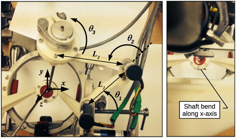
The forward kinematic model of the system is used to calculate the starting instrument tip positions used as the base reference in the position control algorithm for the manipulator arm. To calculate the forward kinematics the origin of the base coordinate frame is placed at the incision site and aligned with the z axis along the endoscope shaft as shown in Fig. 6 and as discussed in [39]. Fig. 6 also shows the startup configuration of the right side of the system and includes starting joint angles in radians and variable labels for offsets and link lengths. Initial conditions are given as
Figure 6. Surgical robot system kinematics variables and parameters.
| (1) |
with rotational variables in radians and the translational variable in mm.
Calculation of the forward kinematics equations for the position of the robotic instrument tips is somewhat more complicated than for a typical serial-link manipulator due to the two passive universal joints, which consist of the gimbal joint where each instrument is clamped to its instrument manipulator, and the insertion point where the instrument enters the body. Kinematics equations are therefore calculated in three parts consisting of the calculation of the gimbal axis intersection point from the manipulator joint variables, the calculation of the position of the end of the straight portion of the instrument inside the body from the gimbal position, and the position of the instrument tip from the instrument position, direction, and rotation about its own axis.
The (Gx, Gy, Gz) position of the joint axis intersection of the manipulator arm universal joint, or gimbal, is calculated using the following equations for a two link serial link manipulator with link lengths L1 and L2 as described in [40]:
| (2) |
| (3) |
| (4) |
Next the length of instrument shaft between the gimbal and incision point, Lext, and the length of the straight section of the instrument shaft inside the body protruding below the incision point, Lint, are determined. Lrod is the total length of the instrument shaft from the center of gimbal motion to the end of the straight section of the instrument shaft axis.
| (5) |
| (6) |
The position of the end of the straight portion of the instrument shaft axis in base frame coordinates is calculated as:
| (7) |
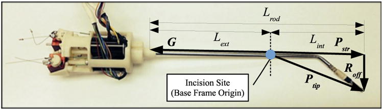
The perpendicular offset vector between the instrument shaft axis and the end-effector tip must be calculated in order to determine the position of the end-effector tip in base frame coordinates, due to the bend by the tip of the instrument. This offset vector accounts for the 45 degree shaft bend in the angled instruments. The vector can be calculated by taking the cross product of the Pstr unit vector and the base frame Ŷ unit vector, multiplied by the offset distance between the instrument shaft and end-effector tip, Loff. This cross product is possible because the home configuration of the system orients the offset vector along the x axis of the base frame. Fig. 8 shows the measurements corresponding to the instrument shaft variables referenced above.
Figure 8. Robotic instrument shown with shaft dimensions used in kinematic calculations.
| (8) |
Thus the initial position of the end-effector tip at system startup expressed in base frame coordinates can be described as:
| (9) |
Inverse Kinematics
A hybrid of position and velocity control has been utilized for the surgical robot presented in this thesis. High-level position control allows accurate motions with minimal control drift and joint-level velocity control generates smooth motor motions to minimize overshoot and control lag. Thus the hybrid architecture employed creates a control structure that maintains positional accuracy in relation to master controller inputs while performing controlled, intuitive motions during operation. To execute this algorithm an array of target joint positions must be generated to match the end-effector tip position and orientation with the master controller input at each time step. The inverse kinematic model used to generate these target joint positions is discussed below.
The control loop first determines the target end-effector tip position and orientation in base frame coordinates at each control update as follows:
| (10) |
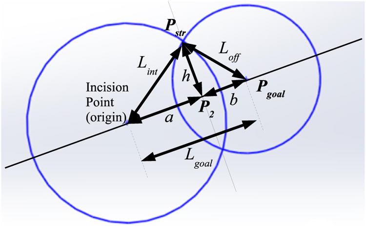
Next the target position of the end of the straight portion of the instrument shaft is determined before considering the rotation of the shaft (θ3 = 0). The magnitude of the distance from the incision point end of the straight section of the instrument shaft Lint and the distance Lgoal from the incision point to Pgoal are calculated. These values are used to determine the projection point in base frame coordinates by determining the intersection of two circles. One circle is centered at the incision point with a radius equal to the magnitude of the distance between the incision and the projection point, and the second circle is centered at Pgoal with a radius Loff.
The sides of the triangle formed by the incision point, instrument tip, and the end of the straight part of the instrument are described as:
| (11) |
| (12) |
Since the vector from the incision to the projected point of the end-effector tip onto the instrument shaft axis (Pstr) is first determined before any shaft rotation, Pstry is equal to Pgoaly. Therefore Pstrx and Pstrz are defined by circle intersection as calculated below. See Fig. 9 for an illustration of the geometry.
Figure 9. Circle intersection diagram to determine instrument shaft points from Eqns. (11-19).
| (13) |
| (14) |
| (15) |
| (16) |
| (17) |
| (18) |
| (19) |
Next the vector from the incision point to the end of the straight rod section Pstr can be rotated by θ3 about the unit vector from the incision point to the tip goal position Pgoal using the following Rodriques formula rotation calculations [41]:
| (20) |
| (21) |
| (22) |
where s3 = sin(θ3), c3 = cos(θ3), and υ3 = 1 − cos(θ3).
The target manipulator gimbal position G can be calculated from Pstr using the following equation set:
| (23) |
| (24) |
| (25) |
The target gimbal position is then used to determine the target joint positions (θ1, θ2, θ3, and d) needed to place the end-effector tip in the position and orientation commanded by the master controller in the given time step. The equations used to calculate joint positions are shown below,
| (26) |
| (27) |
| (28) |
| (29) |
where Δϕmaster is the change in the rotation of the shaft of the handle of the teleoperation master from its initial orientation.
Instrument Wrist Kinematics
The kinematic model used to control the wrist bending motions is the same hybrid style algorithm utilized to control the manipulator arms. The primary function of the orientation control portion of the wrist model is to read changes in the position of the master controller gimbal and changes in the master controller stylus rotation and map those inputs to wrist motions coupled to the orientation and position of the instrument shaft and end-effector. This allows for wrist bending directions to remain aligned with the instrument shaft as viewed by the user during operation. The following equations are used to generate the desired wrist joint angles:
| (30) |
| (31) |
| (32) |
where Δαmaster and Δβmaster are the gimbal joint angles from the teleoperation master. The two orthogonal wrist angles θ4 and θ5 are closely proportional to their corresponding actuator motor shaft angles, as the motors turn drive wheels which are directly connected to the wrist flex actuation wires, as shown in Fig. 5. The instrument wrist kinematics are thus similar to previous instruments as described in [38] and [37].
Position Control
The array of instrument and manipulator goal joint positions generated by the kinematic models are used along with the current joint position values to generate motor velocity commands. These commands are calculated based on the error between the target and current positions at each time step. Each goal joint position is bounded by individual upper and lower joint limits based on the specific geometries of each joint. Commanded positions beyond the limits are capped at the limit bound to prevent damage to the surgical robot arising from attempts to satisfy commanded motions not physically supported by the system. The filtered joint positions are used to determine motor velocity commands in lieu of the absolute kinematic goal positions. All velocities are formulated using a simple error based proportional gain except for the instrument shaft rotation θ3. The velocity command for this joint is modified to compensate for additional effective shaft rotations introduced by coupled motions of the manipulator links during operation.
The joint limits for each the actuated joints are as follows,
| (33) |
| (34) |
| (35) |
| (36) |
| (37) |
| (38) |
The motorized joints are given velocity commands proportional to the angular error between goal and sensed angles. The motor velocity command equations are:
| (39) |
| (40) |
| (41) |
| (42) |
| (43) |
| (44) |
The encoder and gearhead scaling factors are included in the motor control gains, so that tuning of the high-level feedback controller is simple and straightforward. The control based on relative position errors between the teleoperation masters and the instrument tip positions, rather than absolute position control, simplifies the implementation of variable scaling factors and index offsets between the teleoperation masters and the robot positioning. Phantom Omni haptic interfaces from Geomagic/3D Systems are used as teleoperation masters for the left and right manipulators and surgical instruments. Each of the brushless DC motors in the robotic system is driven by an MCBL 3006 motor controller from Faulhaber which is connected by to the high-level kinematic controller on a PC by RS-232 serial communication. The update rate of the high-level PC controller is approximately 100 Hz.
Failsafe operation has been implemented at the PC control level by confirming that all sensor data and calculated motor commands are within acceptable bounds at each control update before issuing commands to the motor controllers. If any fault is detected, the corresponding manipulator and instrument are disabled. Individual motor controllers operate with current limits so that contact forces greater than a desired level cannot be generated by surgical instruments, so that damage from undesired collisions with bodily tissues may be minimized. Although this prototype system has not as yet been certified for commercial or clinical use, its actuation hardware and control software are similar to those of the ViKY endoscope manipulator from EndoControl Inc. which has received FDA approval in the United States and CE marking certification in Europe.
Operational Parameters
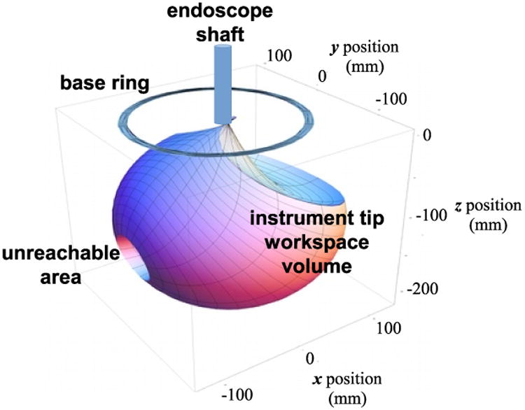
The workspace and motion range of a single instrument tip, with the endoscope shaft and support frame in the vertical position and the base ring in a fixed orientation is shown in Fig. 7. This volume is approximately spherical with a diameter of 200 mm and a small internal unreachable area on one side due to self-collisions between the manipulator links as the joint angle θ2 approaches 180 degrees. In practice the unreachable volume does not pose an obstacle to instrument manipulation, as rotation of the base ring or inclination of the endoscope frame moves the unreachable volumes away from any desired target locations for the instrument tips.
Figure 7. Instrument tip workspace motion range.
The maximum tissue contact force generation by the instrument end effectors is determined by the wrist structural stiffness and actuator torques and is approximately 5 N. The maximum cutting or grasping forces by the instrument jaws is approximately 30 N. These forces are similar to those measured in [37], as the earlier surgical robot system used a similar wrist mechanism.
The maximum speed of the instrument tips depends on the manipulator configuration and was not a primary design consideration for the system. In practice, tip speeds of 50 mm/sec in any direction were reliably achievable within the motion range as shown.
Teleoperation
The control of the left and right manipulators and instruments in the surgical robot system uses 3D position and orientation command setpoints acquired from teleoperation master devices, as pictured in Fig. 2. Phantom Omni haptic interfaces from Geomagic/3D Systems are used for this purpose, as described in [42]. These devices consist of a jointed linkage attached to a pen-shaped handle by a gimbal joint so that its user can easily move the pen in position and orientation through a range of motion of approximately 100 mm and 180 degrees in all directions. 3D force feedback to the user may also be generated with these devices, but this function is not used for teleoperation of the surgical robot system. The HDAPI application programming interface and software libraries provided with the devices are used to read the pen handle positions and orientations from the devices to be used as teleoperation command setpoints. This teleoperation control is based on relative position errors between the teleoperation masters and the instrument tip positions rather than absolute position control, which simplifies the implementation of variable scaling factors and index offsets between the teleoperation masters and the robot positioning.
Results
We have demonstrated the functionality of the described teleoperated system first by tracking the instrument motion while following sample command trajectories to confirm position control performance, then by executing a sample teleoperated pick-and-place task. The trajectories consisted of 30 mm square and cube-shaped figures to be traced by the instrument tip. The pick-and-place task was to transfer a set of rings from one set of pegs to another.
Trajectory Following
To evaluate the conrolled motion accuracy of the surgical manipulators, an optical motion tracker (Polaris Vicra from Northern Digital Inc.) was used to detect the 3D position of a single instrument tip while following two teleoperation command trajectories.
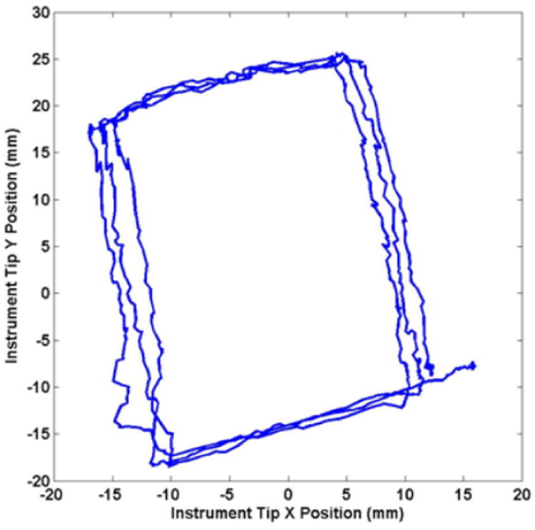
The first trajectory following results were performed with a straight instrument shaft, without the bend shown in Fig. 8. The experimental setup is shown in Fig. 10. Four position marker reflector spheres were fixed to the top end of the manipulated instrument, and the position of the instrument tip was calculated from the rigid-body motion recorded by the motion tracker. Fig. 11 shows x and y components of the recorded instrument tip trajectory resulting from tracing a 30 mm square on a horizontal surface three times by hand with the tip of the stylus of the Phantom Omni teleoperation master. The base ring of the system was rotated by approximately 15 degrees and the frame inclined by 20 degrees in this setup so that the coordinate frames of the instrument manipulator and the motion tracker are not aligned, resulting in a rotated planar trajectory with a somewhat rectangular aspect ratio in Fig. 11.
Figure 10. Optical motion tracking setup to measure motion trajectories.
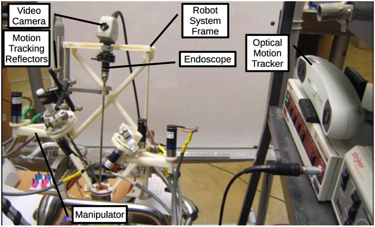
Figure 11. Recorded instrument tip motion with straight shaft and planar trajectory.
The second trajectory to be followed was a 30 mm cube shape, composed of straight line motions in three dimensions. The command trajectory was precomputed to be executed in approximately 12 seconds. To obtain these results, a single position marker was used, fixed at the tip of a metal rod in the size and shape of a bent instrument. This bent rod instrument mockup and reflector are shown in place under the surgical robot base in Fig. 12. The recorded instrument tip trajectory following motion is shown in Fig. 13.
Figure 12. Optical motion tracking setup to measure motion trajectories.
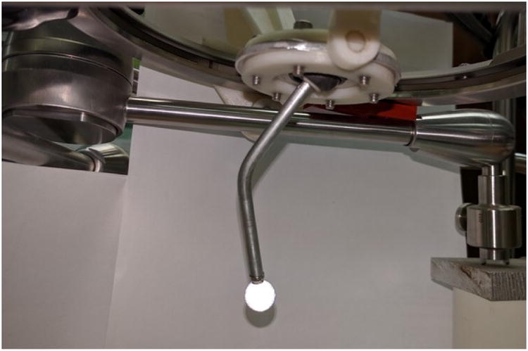
Figure 13. Recorded instrument tip trajectory with bent shaft and spatial trajectory.

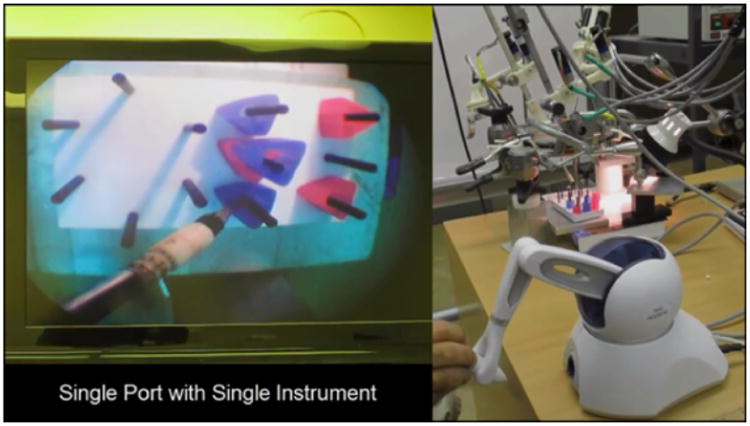
Peg Placement Task
To demonstrate successful use of the robotic system in a surgical training task, we used a single manipulator and instrument to complete a set of peg transfers. The setup for this single manipulator validation task is shown in Fig. 14, including the view through the surgical endoscope, the Phantom Omni teleoperation master, and the surgical robot system. This peg transfer task is one of the standardized surgical skill tasks from the SAGES Fundamentals of Laparosopic Surgery [43], adapted for a single instrument. The goal of the task is to pick up each ring from a peg and transfer it to a different peg on the opposite side of the task board, without dropping any. In this preliminary trial, the author performed 9 peg transfers in a total of 195 seconds, with a minimum transfer time of 14 seconds, maximum of 30 seconds, mean of 21.7 seconds and standard deviation of 5.5 seconds. This peg transfer performance is sufficient to pass the single-instrument modified SAGES FLS peg transfer skill test.
Figure 14. Peg transfer task using single-port teleoperated surgical robot system.
Discussion
The trajectory following plots in Figs. 11 and 13 show position errors which can be attributed to friction and hysteresis in the manipulator joints and instrument insertion pivot point, and flexion and vibration in the cantilever mounts supporting the robotic system above the table. It can be noted that the results from Fig. 11 show more high frequency errors and differences between the repeated square trajectories, while the results from Fig. 13 show a more distorted trajectory shape. These differences can be attributed to differences in the experimental setups.
In the first case, the motion tracking was performed using multiple position marker reflectors attached to the top end of the instrument, the instrument was inserted through a rubber sheet at the insertion point at the base of the robot, and a straight instrument shaft was used. The location of the position markers produced more vibrations in the measured trajectory, while the rubber sheet at the insertion point of the instrument did not completely constrain the motion of the instrument perpendicular to the insertion plane and produced significant static friction on the instrument shaft, leading to the high frequency errors and differences between repetitions of the square trajectory.
For the second case, with a bent instrument and a single reflector at the tip, a small universal joint gimbal was used at the instrument incision point. This gimbal joint constrained the planar motion of the instrument shaft at the insertion point more effectively, while producing much less friction in response to the angular and insertion motions of the instrument during the trajectory following, resulting in smoother motion with less vibration. With the bend in the instrument shaft, the shaft rotation must be controlled during trajectory following to position the tip, but the shaft rotation is less precise than the other joint rotations due to the 3D-printed pair of spur gears between the motor shaft and instrument shafts. The lack of precision in this rotation is likely to be responsible for the trajectory distortion errors shown in Fig. 13.
The position accuracy of this single-port teleoperated minimally-invasive surgical system is less than that of our previous system [37], due primarily to fabrication using 3D-printed parts and ABS plastic rather than precision machined stainless steel. Nevertheless, the described system is capable of executing a basic surgical training task in teleoperation. Absolute position accuracy is less critical in teleoperated tasks, as a human operator uses visual feedback during teleoperation. Further planned work will focus on improving position accuracy through redesigned parts and calibrated actuation, and system validation with more advanced surgical skill training tasks and two robotic instruments used together.
Comparison to Other SPA Robotic Systems
The defining novel features of our described single-port surgical robot system are its configuration with an endoscope and two instrument manipulators fixed to a single movable frame and base ring and inserted independently through the single incision, and its low-cost, rapid fabrication method using mostly 3D-printed parts. Each instrument tip has a 200 mm range of motion and can exert contact forces of 5 N in all directions.
A more common configuration of many other single-port surgical robot systems is a single shaft which separates into multiple articulated branches with endoscope or instrument end effectors inside the body. These ‘Y-type’ systems often have limited motion ranges and force interaction capabilities, but the SAIT citesait and PLAS systems [27] systems have novel features to overcome these limitations. The SAIT system uses a remote center of motion mechanism with a hyperredundant guide tube in order to reach most of the abdominal cavity, and an interaction force capability of 1 kgf or approximately 10 N is reported. The PLAS system uses plate springs rather than wires to transmit actuation forces, resulting in a force transmission capability of over 14 N, and additional prismatic joints are used in the arms to extend their motion ranges to over 100 mm. A lack of modularity remains a disadvantage of these and other Y-type systems, as individual instruments cannot be exchanged independently.
The single-incision laparoscopic surgical robot from Choi et al is a high-performing example of a system with a configuration similar to ours, with multiple externally-actuated instruments crossing one another at a remote center of motion at the incision point, and bending back to reconverge inside the body. A 10 N force capability an a motion range greater than 200 mm in all directions is reported, however the greater complexity of its mechanisms would require precision fabrication at a much higher cost than our system as described.
Maximum instrument motion speeds are not generally reported in surgical robot publications, most likely because this varies according to joint values and is not a primary design consideration. Successful peg and ring handling or similar surgical skill tasks are demonstrated however, indicating that pratical operational speeds are sufficient for use in surgery.
Avoiding collision between the moving parts of our surgical robot system is somewhat less troublesome than for many other platforms with moving external manipulators because the endoscope and both instruments move together as a unit when the endoscope is reoriented due to the common support frame to which they are mounted, shown in Fig. 3. Furthermore, the bends in the instruments inside the body to achieve end effector triagulation impose a minimum angular separation between the instrument shafts whenever the tips are in close proximity to one another at the operative site. The angular separation of the shafts produces separation between the instrument motor assemblies at the exterior end of the instruments on the right and left sides of the system, as can be seen in Fig. 1. These instrument motor assemblies are also designed to occupy a compact cylindrical volume of 57 mm in diameter and 108 mm in height to minimize collision configurations of the instruments.
Conclusion
With this project we have demonstrated the feasiblity and potential of a single-port laparoscopic teleoperated robotic surgical system with a novel kinematic design and using 3D printing fabrication techniques. The distinctive features of the system design are that an endoscope holder and two surgical instrument manipulators are attached to a common base and support frame which can rotate and tilt these three components together while a rigid endoscope and the two instruments are inserted through a single incision. The articulated instruments and their instrument manipulators are independently teleoperated and the frame orientation and endoscope insertion depth can be controlled by pedals or by voice commands. Cost reduction aims have been achieved through the utilization of inexpensive, easy to produce 3D printed ABS components. The use of these components allows for reductions in material and manufacturing costs as well as substantial reductions in complexity, fasteners, and maintenance costs. These simplified design and fabrication procedures compared to machined parts enabled rapid development of a fully functional prototype. Preliminary trajectory following and peg transfer experimental results indicate that the system performance is sufficient for common basic minimally invasive surgical tasks.
Acknowledgments
The authors gratefully acknowledge the support of a Technology Resarch Grant from Intuitive Surgical Inc. and from NIH grant #5R21EB6073.
Financial Support: Intuitive Surgical Clinical and Technology Research Grant, NIH/NIBIB grant #5R21EB6073-2
References
- 1.Fuchs KH. Minimally Invasive Surgery. Endoscopy. 2002;34:154–159. doi: 10.1055/s-2002-19857. [DOI] [PubMed] [Google Scholar]
- 2.Dhumane PW, Diana M, Leroy J, Marescaux J. Minimally invasive single-site surgery for the digestive system: A Technological Review. Journal of Minimally Invasive Surgery. 2011 Jan;7(1):40–51. doi: 10.4103/0972-9941.72381. [DOI] [PMC free article] [PubMed] [Google Scholar]
- 3.Ahmed K, Wang TT, Patel VM, Nagpal K, Clark J, Ali M, et al. The Role of Single-incision Laparoscopic Surgery in Abdominal and Pelvic Surgery: A Systematic Review. Surgical Endoscopy. 2010 Jul;:1–19. doi: 10.1007/s00464-010-1208-6. [DOI] [PubMed] [Google Scholar]
- 4.Halim I, Tavakkolizadeh A. NOTES: The next surgical revolution? International Journal of Surgery. 2008 Aug;6(4):273–276. doi: 10.1016/j.ijsu.2007.10.002. [DOI] [PubMed] [Google Scholar]
- 5.Horgan S, Cullen JP, Talamini MA, Mintz Y, Ferreres A, Jacobsen GR, et al. Natural Orifice Surgery: Initial clinical experience. Surgical Endoscopy. 2007 Jul;23(7):1512–1518. doi: 10.1007/s00464-009-0428-0. [DOI] [PMC free article] [PubMed] [Google Scholar]
- 6.Baron TH. Natural Orifice Transluminal Endoscopic Surgery. British Journal of Surgery. 1994 Jan;94(1):1–2. doi: 10.1002/bjs.5681. [DOI] [PubMed] [Google Scholar]
- 7.Isariyawongse JP, McGee MF, Rosen MJ, Cherullo EE, Ponsky LE. Pure natural orifice transluminal endoscopic surgery (NOTES) nephrectomy using standard laparoscopic instruments in the porcine model. Journal of Endourology. 2008 May;22(5):1087–1091. doi: 10.1089/end.2007.0404. [DOI] [PubMed] [Google Scholar]
- 8.Clark J, Sodergren M, Noonan DP, Darzi A, Yang GZ. The Natural Orifice Simulated Surgical Environment (NOSsE): Exploring the Challenges of NOTESWithout the Animal Model. Journal of Laparoendoscopic and Advanced Surgical Techniques. 2009;19:211–214. doi: 10.1089/lap.2008.0357. [DOI] [PubMed] [Google Scholar]
- 9.Clayman RV, Box GN, Abraham JB, Lee HJ, Deane LA, Sargent ER, et al. Rapid communication: transvaginal single-port NOTES nephrectomy: initial laboratory experience. Journal of Endourology. 2007 Jun;21(6):640–644. doi: 10.1089/end.2007.0145. [DOI] [PubMed] [Google Scholar]
- 10.Chow A, Purkayastha S, Aziz O, Paraskeva P. Single-incision laparoscopic surgery for cholecystectomy: an evolving technique. Surgical Endoscopy. 2010 Mar;24(3):709–714. doi: 10.1007/s00464-009-0655-4. [DOI] [PubMed] [Google Scholar]
- 11.Raman JD, Cadeddu JA, Rao P, Rane A. Single-incision laparoscopic surgery: initial urological experience and comparison with natural-orifice transluminal endoscopic surgery. BJU International. 2008 Jun;101(12):1493–1496. doi: 10.1111/j.1464-410X.2008.07586.x. [DOI] [PubMed] [Google Scholar]
- 12.Neto MG, Ramos A, Campos J. Single port laparoscopic access surgery. Techniques in Gastrointestinal Endoscopy. 2009 Apr;11(2):84–93. [Google Scholar]
- 13.Escobar PF, Haber GP, Kaouk J, Kroh M, Chalikonda S, Falcone T. Single-port surgery: laboratory experience with the daVinci single-site platform. Journal of the Society of Laparoendoscopic Surgeons. 2011;15(2):136–141. doi: 10.4293/108680811X13022985132128. [DOI] [PMC free article] [PubMed] [Google Scholar]
- 14.Pott P, Kopfle A, Wagner A, Badreddin E, Manner R, Weiser P, et al. Proceedings of the Scientific Workshop on Medical Robotics, Navigation and Visualization. Remagen: 2004. State of the Art of Surgical Robotics; pp. 375–382. [Google Scholar]
- 15.Lum M, Friedman D, Sankanarayanan G, King H, Fodero K, Leuschke R, et al. The RAVEN: Design and Validation of a Telesurgery System. International Journal of Robotics Research. 2009 Sep;28(9):1183–1197. [Google Scholar]
- 16.Bell B, Stieger C, Gerber N, Arnold A, Nauer C, Hamacher V, et al. A Self-developed and Constructed Robot for Minimally Invasive Cochlear Implantation. Acta Oto-laryngologica. 2012 Apr;4(132):355–360. doi: 10.3109/00016489.2011.642813. [DOI] [PubMed] [Google Scholar]
- 17.Bajo A, Dharamsi L, Netterville J, Garret C, Simaan N. IEEE International Conference on Robotics and Automation. Karlsruhe: 2013. Robotic-Assisted Micro-Surgery of the Throat: The Trans-Nasal Approach; pp. 232–238. [Google Scholar]
- 18.Hassan T, Hameed A, Nisar S, Kamal N, Hasan O. Al-Zahrawi : A Telesurgical Robotic System for Minimal Invasive Surgery. IEEE Systems Journal. 2016 Sep;10(3):1035–1045. [Google Scholar]
- 19.Guthart GS, Salisbury JK. IEEE International Conference on Robotics and Automation. San Francisco: 2000. The Intuitive (TM) telesurgery system: Overview and application; pp. 618–621. [Google Scholar]
- 20.Palep JH. Robotic assisted minimally invasive surgery. Journal of Minimal Access Surgery. 2009 Jan;5(1):1–7. doi: 10.4103/0972-9941.51313. [DOI] [PMC free article] [PubMed] [Google Scholar]
- 21.White MA, Haber GP, Kaouk JH. Robotic single-site surgery. Current opinion in urology. 2010;20(1):86–91. doi: 10.1097/MOU.0b013e3283337a10. [DOI] [PubMed] [Google Scholar]
- 22.Kaouk JH, Goel RK, Haer GP, Crouzet S, Stein RJ. Robotic single-port transumbilical surgery in humans: initial report. BJU International. 2009;103(3):366–369. doi: 10.1111/j.1464-410X.2008.07949.x. [DOI] [PubMed] [Google Scholar]
- 23.Kroh M, El-Hayek K, Rosenblatt S, Chand B, Escobar P, Kaouk J, et al. First human surgery with a novel single-port robotic system: cholecystectomy using the da Vinci Single-Site platform. Surgical endoscopy. 2011;25(11):3566–3573. doi: 10.1007/s00464-011-1759-1. [DOI] [PubMed] [Google Scholar]
- 24.Haber GP, White M, Autorino R, Escobar P, Kroh M, Chalikonda S, et al. Novel Robotic DaVinci Instruments for Laparoendoscopic Single-Site Surgery. Urology. 2010;76(6):1279–1282. doi: 10.1016/j.urology.2010.06.070. [DOI] [PubMed] [Google Scholar]
- 25.Xu K, Goldman RE, Ding J, Allen PK, Fowler DL, Simaan N. IEEE/RSJ International Conference on Intelligent Robots and Systems. St. Louis: 2009. System Design of an Insertable Robotic Effector Platform for Single Port Access (SPA) Surgery; pp. 5546–5552. [Google Scholar]
- 26.Simaan N, Bajo A, Reiter A, Wang L, Allen P, Fowler D. Lessons Learned Using the Insertable Robotic Effector Platform (IREP) for Single-port Access Surgery. Journal of Robotic Surgery. 2013 Sep;7(3):235–240. doi: 10.1007/s11701-013-0400-9. [DOI] [PubMed] [Google Scholar]
- 27.Cheon B, Gezgin E, Ji DK, Tomikawa M, Hazhizume M, Kim HJ, et al. A single port laparoscopic surgery robot with high force transmission and a large workspace. Surgical Endoscopy. 2014 Sep;28(9):2719–2729. doi: 10.1007/s00464-014-3534-6. [DOI] [PubMed] [Google Scholar]
- 28.Roh SG, Lee Y, Lee J, Ha T, Sang T, Moon KW, et al. IEEE Engineering in Medicine and Biology Society International Conference. Milan: 2015. Development of the SAIT Single-Port Surgical Access Robot; pp. 5285–5290. [DOI] [PubMed] [Google Scholar]
- 29.Wortman T, Strabala K, Lehman A, Farritor S, Oleynikov D. Laparoendoscopic Single-site Surgery Using a Multi-functional Miniature in Vivo Robot. The International Journal of Medical Robotics and Computer Assisted Surgery. 2011 Mar;7(1):17–21. doi: 10.1002/rcs.362. [DOI] [PubMed] [Google Scholar]
- 30.Piccigallo M, Scarfogliero U, Quaglia C, Petroni G, Valdastri P, Menciassi A, et al. Design of a Novel Bimanual Robotic System for Single-Port Laparoscopy. IEEE/ASME Transactions on Mechatronics. 2010 Dec;15(6):871–878. [Google Scholar]
- 31.Can S, Staub C, Knoll A, Fiolka A, Schneider A, Feussner H. IEEE RAS/EMBS International Conference on Biomedical Robotics and Biomechatronics. Rome: 2012. Design, development and evaluation of a highly versatile robot platform for minimally invasive single-port surgery; pp. 817–822. [Google Scholar]
- 32.Shin WH, Kwon DS. Surgical Robot System for Single-port Surgery with Novel Joint Mechanism. IEEE Transactions on Biomedical Engineering. 2013 Apr;60(4):937–944. doi: 10.1109/TBME.2013.2242070. [DOI] [PubMed] [Google Scholar]
- 33.Choi H, Kwak HS, Lim YA, Kim HJ. Surgical Robot for Single-Incision Laparoscopic Surgery. IEEE Transactions on Biomedical Engineering. 2014 Sep;61(9):2458–2466. doi: 10.1109/TBME.2014.2320941. [DOI] [PubMed] [Google Scholar]
- 34.Kockerling F, Lange V. Hamlyn Symposium on Medical Robotics. London: 2013. Robotic Technologies in Bariatric Surgery; pp. 1–2. [Google Scholar]
- 35.Veljovich D, Paley P, Drescher C, Everett E, Shah C, P P., III Robotic Surgery in Gynecologic Oncology: Program Initiation and Outcomes after the First Year with Comparison with Laparotomy for Endometrial Cancer Staging. Americal Journal of Obstetrics and Gynecology. 2008 Jun;198(6):679.e1679–e10. doi: 10.1016/j.ajog.2008.03.032. [DOI] [PubMed] [Google Scholar]
- 36.Long JA, Cinquin P, Troccaz J, Voros S, Berkelman P, Descotes JL, et al. Development of Miniaturized Light Endoscope-Holder for Laparoscopic Surgery. Journal of Endourology. 2007;21(8):911–914. doi: 10.1089/end.2006.0328. [DOI] [PubMed] [Google Scholar]
- 37.Berkelman P, Ma JA. Compact Modular Teleoperated Robotic System for Laparoscopic Surgery. International Journal of Robotics Research. 2009 Sep;28(9):1198–1215. doi: 10.1177/0278364909104276. [DOI] [PMC free article] [PubMed] [Google Scholar]
- 38.Meer FV, Giraud A, Esteve D, Dollat X. International Conference on Intelligent Robots and Systems. Alberta: IEEE/RSJ; 2005. A Disposable Plastic Compact Wrist for Smart Minimally Invasive Surgical Tools; pp. 919–924. [Google Scholar]
- 39.Berkelman P, Okamoto S. IEEE/EMBS International Conference on Biomedical Robotics and Biomechatronics. Rome: 2012. Compact Modular System Design for Teleoperated Laparoendoscopic Single Site Surgery; pp. 905–906. [Google Scholar]
- 40.Okamoto S. MS Thesis. University of Hawaii; Honolulu: 2013. Compact Modular System Design for Teleoperated Laparoendoscopic Single Site Surgery. [Google Scholar]
- 41.Craig JJ. Introduction to Robotics: Mechanics and Control. Upper Saddle River NJ: Pearson Prentice Hall; 2005. [Google Scholar]
- 42.Massie TH, Salisbury JK. Proceedings of the ASME winter annual meeting, symposium on haptic interfaces for virtual environment and teleoperator systems. Vol. 55. Chicago: 1994. The PHANToM Haptic Interface: A Device for Probing Virtual Objects; pp. 295–300. [Google Scholar]
- 43.Lum M, Friedman D, Sankaranarayanan G, King H, Wright A, Sinanan M, et al. Objective assessment of telesurgical robot systems: Telerobotic FLS. Studies in health technology and informatics. 2008;132:263–265. [PubMed] [Google Scholar]