Abstract
We have developed a new headstage architecture as part of a smart experimental arena, known as the EnerCage-HC2 system, which automatically delivers stimulation and collects behavioral data over extended periods with minimal small animal subject handling or personnel intervention in a standard rodent homecage. Equipped with a 4-coil inductive link, the EnerCage-HC2 system wirelessly powers the receiver (Rx) headstage, irrespective of the subject’s location or head orientation, eliminating the need for tethering or carrying bulky batteries. On the transmitter (Tx) side, a driver coil, five high quality (Q) factor segmented resonators at different heights and orientations, and a closed-loop Tx power controller create a homogeneous electromagnetic (EM) field within the homecage 3-D space, and compensate for drops in power transfer efficiency (PTE) due to Rx misalignments. The headstage is equipped with four small slanted resonators, each covering a range of head orientations with respect to the Tx resonators, which direct the EM field towards the load coil at the bottom of the headstage. Moreover, data links based on Wi-Fi, UART, and Bluetooth low energy are utilized to enables remote communication and control of the Rx. The PTE varies within 23.6–33.3% and 6.7–10.1% at headstage heights of 8 and 20 cm, respectively, while continuously delivering >40 mW to the Rx electronics even at 90° rotation. As a proof of EnerCage-HC2 functionality in vivo, a previously documented on-demand electrical stimulation of the globus pallidus, eliciting consistent head rotation, is demonstrated in three freely behaving rats.
Index Terms: Small freely behaving animals, closed-loop power control, inductive wireless power transmission, behavioral neuroscience, longitudinal experiments
I. Introduction
A significant number of preclinical studies designed to better understand normal function of the central nervous system (CNS) and the etiology of neuropathological disorders are conducted in small animal models, mostly rodents, and often require wearable/implantable devices (WIDs) attached to or implanted in the animal body [1], [2]. Traditionally, physical wirings or batteries are used to power or communicate with these WIDs [3], [4]. However, the potential for tangling of or damage to the wires necessitate constant supervision, which often restricts the duration of these experiments. To prevent the animal from getting entangled, battery-powered WIDs have been developed and commercially available [5]–[10]. However, the lifetime of batteries restricts the period of behavioral experiments, particularly when neuromodulation or other power-hungry intervention is involved. If larger batteries are used to extend the duration of the experiment, weight and size of the battery payload may add physical burden and bias the subject behavior.
Moreover, restrictions on movement with frequent manual handling of the animal to attach or detach wires or replace batteries also cause stress in small animals. The environment within homecage has the potential to significantly affect brain neurochemistry in rats and the resulting behavior, suggesting its influence on the quality of the collected data [12]–[15]. To conduct experiments that involve WIDs on small freely behaving animals, researchers must follow a labor intensive routine, such as: 1) transferring the animals from their homecages to the experimental arena, which can be an operant conditioning chamber, 2) grabbing the animals to attach cables, connectors, or wireless headstages, 3) closely observing the animal behavior during the intervention and video recording for subsequent data analysis, 4) grabbing the animals to detach cables and connectors, and 5) returning the animals back to their homecages and eventually to the animal facility [11]. This routine is repeated for every subject, which accumulates to become a chronic stressor for animals and a laborious task for researchers [12]. If any portion of the aforementioned procedure can be reduced or automated, it would have a significant impact on the quality of the experimental results, due to the more normative behavior of the animals.
Researchers have proposed wirelessly-powered and -communicated systems that create less stressful environments for longitudinal experiments on small freely behaving animals [16]–[26]. In the case of inductively-powered WID systems, angular and horizontal misalignments and distance variation between the Tx and Rx coils happen quite frequently in practice as freely behaving animal subjects walk, sniff around, rear, and climb the walls of the cage, as shown in Fig. 1. This will result in significant reduction in the PTE and the amount of power delivered to the load (PDL), to the extent that it may cause malfunction if the condition persists beyond the WID built-in temporary energy storage.
Fig. 1.
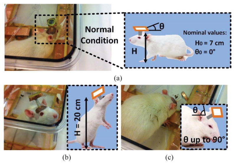
(a) Definition of normal height and orientation of the headstage when the rat is walking. (b) Problem of Tx-Rx increased distance when the animal rear on its hind limbs. (c) Angular misalignment of the headstage attached in a freely behaving animal when the head is turned downward.
To cope omnidirectional wireless powering, several inductive link configurations have been proposed [20]–[27]. In [20] and [21], PTE of the inductive link is maximized by locating the Tx coil, either electronically or mechanically, in the best position to power the Rx coil. This would require real-time tracking of the animal subject and additional electronic or mechanical mechanisms to change the position of the active coil, which add to the complexity and cost of the system. In [22], four triangular slanted Tx resonators encompass four corners of the homecage to create a homogenous PTE across and improve the system robustness against Rx rotation. However, this system still needed real time animal tracking and circuitry for switching the active Tx resonators. In [23] the authors suggested a method with multiple Tx coils located on both top and bottom surfaces of the homecage, which did not require resonators switching. However, placing multiple Tx coils on top of the homecage limited access to the animals and blocked the field of view of imaging modalities that are often used for analyzing the animal behavior. Another method has been proposed in [24] for omnidirectional powering with triple orthogonal Rx coils and a single Tx coil, which is suitable for an enclosed capsule, but the Rx coils block access to the electronics inside the headstage, making it difficult to repair or to have electrode feed-through. In [25]–[27], multiple Tx coils are combined to achieve omnidirectional powering in a 3D space. However, instead of driving only one coil in the proposed EnerCage-HC2 system, a complex control circuit with phase-, time-, and/or frequency-domain modulation is needed to control the Tx coils.
Here we present the EnerCage-HC2 system, which is built around a standard homecage [28] to wirelessly power and communicate with a stimulating headstage in this prototype, with a new 4-coil inductive link design. Wireless power is delivered in the near-field domain at 13.56 MHz, a Federal Communications Commission (FCC) approved operating frequency for industrial, scientific, and medical (ISM) applications. The novel coil arrangement around the homecage enhances the magnetic flux density, mutual coupling, and PTE in the entire 3D space of the homecage, while obviating the need to switch the resonators in and out[29]. To achieve high Q-factor in the Tx resonators at 13.56 MHz without reducing their self-resonance frequency (SRF), they are optimally segmented to achieve a homogeneous PTE. Four slanted High-Q Rx resonators encompass four diagonal planes of the headstage and direct the Tx EM field, which is already homogenized by the Tx resonators [29], towards the Rx load to ensure sufficient PDL at any arbitrary headstage orientation. A closed-loop power control (CLPC) mechanism is established to ensure stable PDL at a user-defined level, > 40 mW in this prototype, despite animal movements. Three freely behaving rats were implanted with electrodes in the globus pallidus (GPi) to observe the well-documented effects of electrical stimulation in this region of the brain.
An overview of the EnerCage-HC2 system is presented in the following section. Section III describes the design of proposed 4-coil inductive link as well as HFSS (ANSYS, Canonsburg, PA) simulation of Poynting vectors and specific absorption rate (SAR) limit. Section IV presents the results of in vivo experiments conducted to verify full functionality of the stimulating headstage, wirelessly-powered by the EnerCage-HC2 system, in a behavioral neuroscience experiment. Finally, section V includes the concluding remarks.
II. EnerCage-HC2 System Overview
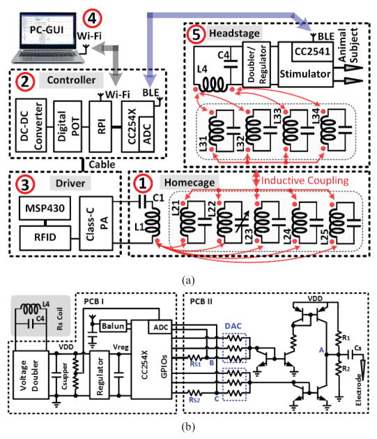
Fig. 2 shows a simplified block diagram of the EnerCage-HC2 system, which is built around a standard rodent homecage. It is equipped with 1) a 4-coil inductive link, 2) an embedded controller based on a customized Raspberry Pi (www.raspberrypi.org), 3) a driver block that includes a Class-C power amplifier (PA), and 4) a personal computer (PC) in charge of data storage and graphical user interface (GUI). EnerCage-HC2 system wirelessly powers 5) a headstage, carried by the animal subject, which includes the Rx coils, and stabilizes its received power in a closed-loop fashion by wirelessly communicating with the controller block through a Bluetooth low energy (BLE) link. The BLE link combined with the Wi-Fi connection between the PC and controller are designed to enable remote control of the EnerCage-HC2 system and facilitate automatic data acquisition.
Fig. 2.
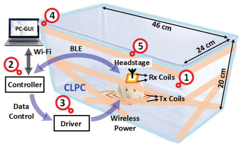
A simplified conceptual representation of the proposed EnerCage-HC2 system for closed-loop wireless powering and communication with a headstage attached to or implanted in a small freely behaving animal.
Fig. 3a shows a simplified schematic of wireless power and data delivery between different components of the EnerCage-HC2 system. Red arrows indicate mutual coupling among a driver coil (L1) and five primary resonators (L21–L25) around the homecage on the Tx side and four resonators (L31–L34) around the headstage and a load coil (L4) on the Rx side. L1 is the only coil driven by the Class-C PA in the driver block, which follows a RFID reader (TRF7960A, Texas Instruments). L4 on the Rx side is the only coil connected to the headstage, which is followed by a voltage doubler and regulator, as shown in Fig. 3b. The PA output power is controlled by its supply voltage, VPA, which is generated by a DC-DC converter in the controller block and delivered through a cable. All high Q-factor resonators in this design, L21–L25 and L31–L34, are simply floating and primality meant to homogenize the magnetic field and strengthen the Tx-Rx coupling to achieve better PTE all across the homecage.
Fig. 3.
Schematic diagram of (a) the key circuits involved in the wireless power transmission from the Tx side to the Rx side and (b) the stimulator circuit implemented on two PCBs in the headstage (see Fig. 8b).
Fig. 3b shows a simplified schematic diagram of the stimulator circuit in the headstage, which involves two stacked PCBs (see Fig. 8b). In PCB-I, the voltage doubler that follows L4 generates a DC voltage, VDD, from the 13.56 MHz power carrier, which is divided in half and sampled by the built-in analog-to-digital converter (ADC) of the headstage micro-controller unit (MCU). The MCU is a CC2541 from Texas Instruments, which also establishes a bidirectional BLE link with the CC2540 MCU in the controller to deliver this information as feedback in the CLPC mechanism that continuously stabilizes VDD, which also sets the stimulator compliance voltage, at a desired user-defined level. The CLPC prevents waste of power in the voltage doubler and the PA when the coupling is too strong by adjusting the PA output power to be just enough to stabilize the VDD despite Tx-Rx coupling variations due to animal movements [30]. To minimize the effects of VDD variations on the MCU and BLE link, it is further regulated onboard to generate Vreg = 3.3 V, before supplying the MCU.
Fig. 8.
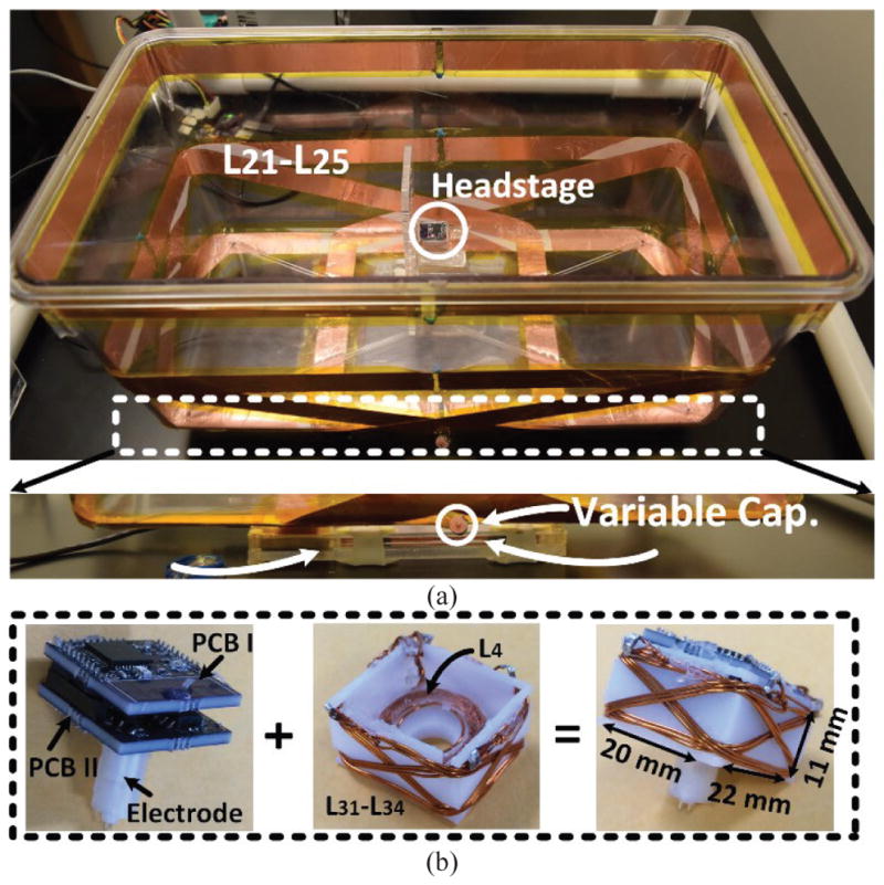
(a) The EnerCage-HC2 proof-of-concept prototype with L1 and its driver located at the bottom of the homecage, and copper foil resonators with a single variable capacitor. (b) A close up view of the headstage and its internal/external components.
In PCB II, a structure involving a complementary current source/sink with a series capacitor, CS, enable charge-balanced bipolar current stimulation. A discrete 3-bit current steering digital to analog converter (DAC) controlled by the MCU general-purpose I/O (GPIO) ports adjusts the stimulus current in anodic and cathodic phases. User-adjustable stimulation parameters in the GUI include stimulation frequency, (40 Hz ~ 200 Hz with 40 Hz resolution), pulse width in cathodic phase (100μs ~ 300μs with 50μs resolution), and stimulation curren t in cathodic phase (75 ~ 525 μA with 75 μA resolution). To monitor the actual status of the stimulation, the headstage MCU also takes a burst of eight consequtive samples from evey biphasic pulse (2 during the cathodic phase and 6 during the anodic phase) from the 1 Ωk current sense resistors, RS1 and RS2, and sends them to the controller via BLE.
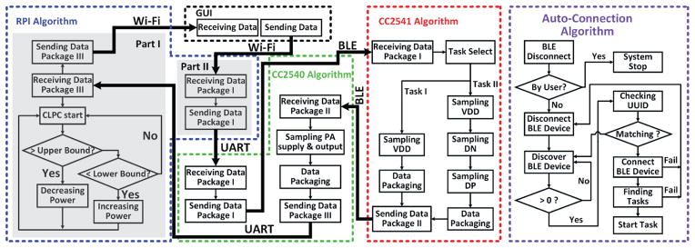
Fig. 4 depicts the communication and control flowchart in EnerCage-HC2 between the two aforementioned CC254x MCUs in the headstage and controller via BLE, between Raspberry Pi (RPi) and the CC2540 MCU in the controller via Universal Asynchronous Receiver/Transmitter (UART), and between the PC and RPi via Wi-Fi. Upon receiving user commands from the GUI in Data Package-I via the Wi-Fi and UART connections, the CC2540 MCU (master) in the controller automatically establishes a BLE link with CC2541 MCU (slave) in the headstage. Once the BLE link is in place, CC2541 delivers the VDD and stimulus current samples to the CC2540 MCU in Data Package-II. The built-in ADC in CC2540 MCU samples the PA supply voltage (DC-DC output) and envelope of the output voltage, which are merged with Data Package-II from the headstage to form Data Package-III. Once RPi receives Data Package-III from CC2540 MCU, it dynamically sets the PA supply voltage based on the CLPC algorithm, which compares VDD and a desired user-defined window. The DC-DC converter output voltage is then adjusted to keep VDD within the desired range despite subject movements and headstage loading variations (e.g. stimulator on/off). If the BLE connection is lost, the CC2540 MCU will reconnect through an auto-connection algorithm.
Fig. 4.
Simplified flowchart of the data communication algorithm in EnerCage-HC2 system, as implemented in the algorithm among CC2541 MCU, CC2540 MCU, and Raspberry Pi (RPi).
III. Design of the 4-Coil Inductive Link
A. Tx Coil Design
Fig. 5 shows the configuration of the 4-coil inductive link with multiple resonators on the Tx and Rx sides in a model constructed in the HFSS environment. Table I presents detailed specifications of each coil based on dimensions of the homecage and headstage. On the Tx side we have a wire-wound coil, L1, which is located under the center of the homecage, driven by the Class-C PA, four High-Q resonators made of copper coil (L21–L24), which are covering four sides of the homecage, and an additional High-Q resonator, L25, wrapped around the rim of the homecage. L21–L24 are tilted to elevate the EM field at the nominal height and deliver sufficient power to the headstage even with maximum angular misalignment (90°). The height of L21–L24 on one side is 7 cm, which is the nominal height of the headstage on the rat head, H0, and extended on the other side to fully overlap with L1 and maximize mutual coupling.
Fig. 5.
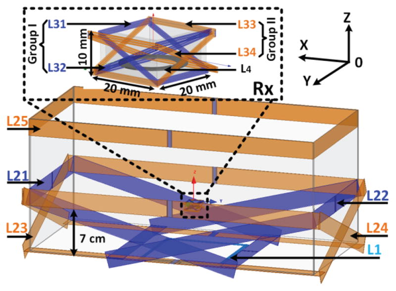
3D view of the 4-coil inductive link, including L1 and L21–L25 under and around the homecage, respectively, on the Tx side, and L31–L34 and L4 around and inside the headstage, respectively, on the Rx side.
Table I.
Specifications of the EnerCage-HC2 Coils on the Homecage (Tx) and Headstage (Rx)
| Parameter | L1 | L21 L22 |
L23 L24 |
L25 | L31~L34 | L4 |
|---|---|---|---|---|---|---|
| Inductance (μH) | 5.46 | 0.88 | 0.94 | 1.01 | 0.68 | 0.96 |
| Q-Factor | 116 | 166 | 160 | 162 | 125 | 142 |
| do (cm) | 13 | - | - | - | - | 1.8 |
| di (cm) | 12.8 | - | - | - | - | 1.3 |
| Length (cm) | - | 32 | 44 | 44 | 2.4 | - |
| Width (cm) | - | 22 | 22 | 24 | 2 | - |
| Conductor width (mm) | - | 25 | 25 | 25 | - | - |
| Thickness (μm) | - | 89 | 89 | 89 | - | |
| Diameter (mm) | 1.45 | - | - | - | 0.4 | 0.4 |
| Number of turns | 3 | 1 | 1 | 1 | 3 | 6 |
| Type of coil | AWG 15 | Foil tape | Foil tape | Foil tape | AWG 26 | AWG 26 |
The key factor in determining the Tx resonator (L21–L25) geometries in EnerCage-HC2 system is the compatibility with standard homecage dimensions that are used for rodents, particularly within a rack, and maximum overlap with the driver coil (L1). Optimizing the 4-coil inductive link means increasing the minimum PTE within the homecage to ensure PDL is enough to keep the headstage on when the CLPC adjusts the Tx power, as opposed to maximizing PTE in the perfectly aligned regions in traditional coil optimization. The optimal size of L1 is directly related to the separation distance (H) and the headstage (Rx) dimension and can be calculated for maximum coupling between driver (L1) and load (L4) coils using AT = AR + π × H 2, where AT and AR are the areas of L1 and L4, respectively.
The subject often climbs the walls of the cage, as shown in Fig. 1b, to perform supported rearing, resulting in a large distance between the headstage and Tx coils, creating an unfavorable case power transmission scenario. We solved this problem by adding a fifth resonator, L25, to the original design of the Tx coils in [29] at the height of 20 cm from the bottom, to enhance the magnetic flux density on top of the homecage. L25, wrapping around the rim of the homecage, compensates for dropping PTE and PDL due to reduced coupling with L21–L24, as the height of the headstage increases. Considering the large dimension of L21–L25, all Tx resonators were segmented to create a more homogeneous magnetic field inside the homecage. Each segment has equal length and links to other segments by small capacitors in a way that the length of each segment is less than λ/10, where λ is the wavelength of the power carrier [31], [32]. The cage made of polycarbonate, which is the substrate for L21–L25, has a relative permittivity of εr = 3. Therefore, for the current induced in Tx resonators, λ is 13 m. To ensure the length of each segments is less than λ/10, L21–L25 were segmented into two identical pieces to prevent phase-inversion in the current distribution along L21–L25, which causes EM field cancellation at the location of L4 [33].
B. Rx Coil Design
On the Rx side, we have L4, which is placed at the bottom of the 3D printed plastic box that houses the headstage electronics and delivers power to the voltage doubler in Fig. 3b, and L31–L34, which cover all sides of the headstage box while being slanted in four directions toward the bottom edges of the box on the other side. Tx and Rx coils are symmetrical with respect to the center of the homecage and headstage, respectively. The diameter and number of turns of the wire-wound L31–L34 and L4 were selected by compromising between the headstage size/weight and coupling coefficient between Tx-Rx resonators and Q-factors of L31–L34 and L4, which ultimately affect the PTE, according to the optimization procedure in [34], at the nominal height of H0 = 7 cm. The result was the choice of 0.4 mm (AWG 26) magnet wire with 3 and 6 turns for L31–L34 and L4.
The coupling between loosely coupled Tx and Rx coils is the dominant factor in determining the PTE of the 4-coil inductive link. Since the size of the headstage is considerably smaller than the homecage, we maximize the effective area of the Rx resonators, through which the Tx magnetic flux passes, to improve their coupling with Tx coils. The maximum effective area of the headstage, which encompass the diagonal planes of the cube, is used to achieve Rx resonators, L31–L34, with the largest possible area. L31–L34 then bend the magnetic flux towards L4 when the headstage is rotated with any arbitrary angle, even in the worst case condition of 90° rotation [35]. For 90° rotation of the headstage, which happens when the rat is sniffing, grooming, resting, or rearing on its hind limbs, L31–L34 guide the magnetic flux that passes through the effective area, one of the side faces of the headstage cube, toward L4.
In [29], we found that the 4-coil link with a single Rx resonator delivers sufficient power to the headstage up to 70° rotation. Therefore, we need Rx resonators with less than 70° rotation, when the headstage is rotated by 70° – 90°. This is achieved by tilting at least one Rx resonator at an angle of 25° compared to the horizontal plane in each four directions of the cubical headstage. As shown in Fig. 5, when the headstage is at maximum 90° rotation, L31 is tilted 65° with respect to the horizon, and can bend sufficient flux towards L4 to power the headstage. With 65° rotation, however, L31 will be tilted 90° with respect to the horizon, and instead, L32 is the resonator with less than 65° tilt, bending the flux towards L4. Similarly, L33 and L34 play the same role with 90° rotation around the vertical axis
C. HFSS Simulation of Poynting vector and SAR
Fig. 6 shows the Poynting vectors (real component of the power density) generated by 3D HFSS model of the 4-coil inductive link. The red areas exhibit the highest directional power flux density, representing the highest rate of power transfer per unit area. Without segmentation, L25 strengthens the power transmission toward the headstage, with one activated portion of the loop. With segmentation in two pieces, L25 produces a strong and uniform power transmission from two sides of the coil. As we increase the number of segments to four, the directional power flux density distribution becomes more uniform. However, the power transfer density is considerably lower, evident from the smaller red area.
Fig. 6.
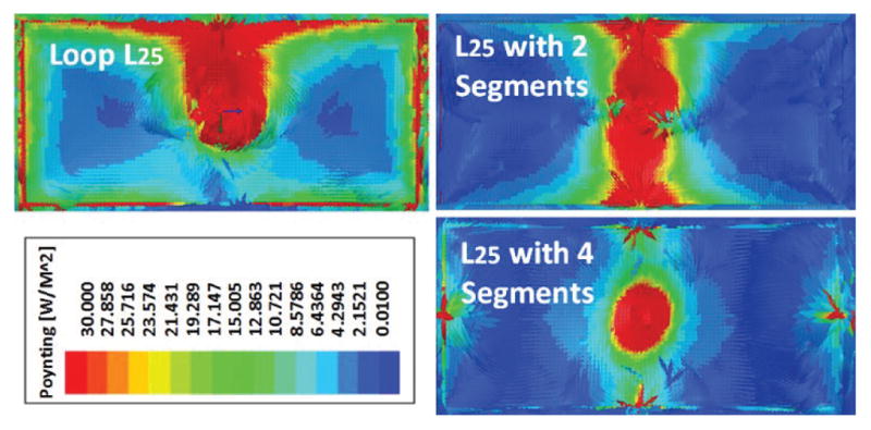
Poynting vector simulations in HFSS, showing top view of L25 as a complete loop, with two segments, and with four segments, when the headstage is located at the center, 20 cm from the bottom of the homecage.
The animal/human body is almost transparent to electro-magnetic field at frequencies below 20 MHz due to the low body tissue absorption rate [36]. Fig. 7 presents the SAR simulation result in HFSS for the rat head and body model. For this simulation setup, the input power is set at 1 W. Since SAR = σ|E|2/ρ is directly related to tissue conductivity, σ, and inversely proportional to density, ρ, we consider the rat model made entirely out of brain tissue with σ = 105 S/m and ρ = 1040 kg/m3, which generates the worst case for SAR simulation. For the rat model in the EnerCage-HC2 system in Fig. 7, the maximum simulated SAR value is 0.15 W/kg. A SAR level of 1.6 W/kg has been designated by the FCC as the limit of radio frequency energy that can be safely absorbed by humans while using cellular phones [37]. Therefore, the maximum allowable transmitted power can be found from 1 W × 1.6 (W/kg)/0.15 (W/kg) = 10.7 W. In the current system, the maximum output power of the PA is limited to 2.5 W, resulting in only a small fraction of power absorbed by the rat body.
Fig. 7.
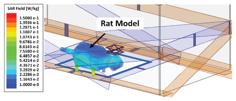
SAR simulation in HFSS, presenting the maximum of the average SAR values for the tissue layers with the proposed 4-coil inductive link.
IV. Experimental Results
A. EnerCage-HC2 Prototype Implementation
Fig. 8 shows the current implementation of Tx and Rx coils. A 46 × 24 × 20 cm3 standard rodent homecage (Alternative Design, Siloam Springs, AR), was used as a base in this prototype with L1 and its driver located at the bottom of cage and L21–L25 encompassing four sides and the rim on the Tx side. All Tx resonators are covered with Kapton® tape (polyimide film) to improve isolation between resonators. Because of the strong coupling among L21–L25, only one of them needs a variable capacitor for fine tuning of the entire Tx at 13.56 MHz, while the others have fixed capacitors. On the Rx side, electronics in the form of two stacked PCBs are protected against moisture and mechanical damage in a 3D printed 11 (H) × 20 (W) × 22 (L) mm3 box with L4 attached at the bottom, and L31–L34 encompassing four diagonal planes. The headstage weighs 7 g, which is suitable for rats. A 1.1 cm 2-pin collar assembly (305/CP) from PlasticsOne (Roanoke, VA) is mounted on the bottom of PCB II to connect the headstage to a pair of implanted electrodes on the rat head.
To accurately measure the PTE of the 4-coil inductive link with actual load impedance, we measured S21 by a Network Analyzer (NA) in Fig. 9 configuration. Each LC-tank is tuned at the carrier frequency, and the entire link forms a two-port network including any configuration of coupled resonators between the driver (L1) and load (L4) coils. L1 is driven by Port-1 of the NA, which default impedance is 50 Ω. On the load side, 43 mW power consumption of the headstage at 5.5 V, results in RL = 118 Ω. Therefore, an additional resistor, RL′, was added in series with Port-2 of the NA to achieve RL = RL′ + 50 Ω. The transmission coefficient under the actual load, S21′, and PTE were then calculated from,
Fig. 9.
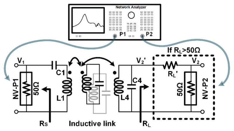
PTE measurement setup using a VNA when RL > 50 Ω.
| (1) |
| (2) |
where V1, V2, and V2′ (V2′ = V2 × (RL′+50)/50) are the voltages across NA Port-1, Port-2, and load coil.
B. Horizontal and Angular Misalignments
To measure the PTE distribution across the homecage, the bottom of the cage was marked by an X × Y grid with 2.75 cm spacing and the headstage was swept at various heights, resulting in Fig. 10a heat maps. Considering the significant size difference between the headstage and homecage, the center of the cage generally has a weaker magnetic flux density, mutual coupling, and PTE compared to its perimeter. At H = 4 cm, PTE slightly drops at the corners of the homecage, which are not covered by Tx resonators, L21–L24. With proper segmentation, however, L21–L25 generate a strong and uniform PTE distribution across the homecage, especially at H = 8 cm, which is close to the nominal height of rats. As H increases, PTE is higher in the center of the cage compared to its perimeter because of the collective effect of L21–L24. The segmented L25 further strengthens the magnetic flux density at higher headstage elevations, as demonstrated in Fig. 10b, which compares the PTE in a vertical plane with and without L25. For H > 14 cm, L25 has had a positive effect on increasing the PTE across the homecage. Overall, our measurements showed that the proposed coil/resonator design can guaranty PTE > 6.7% anywhere within the volume of inside the homecage.
Fig. 10.
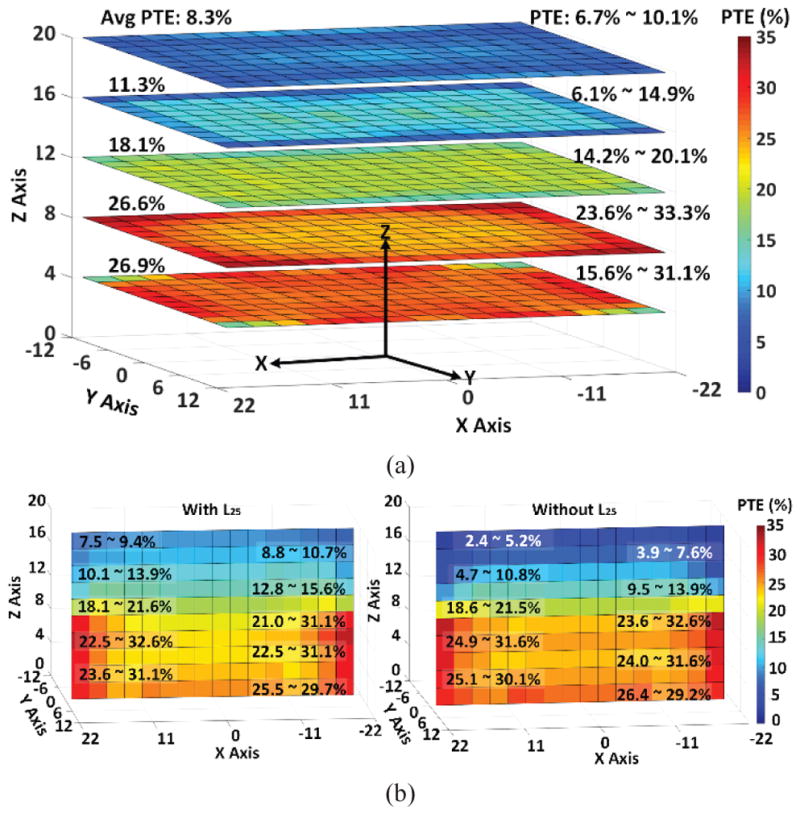
(a) Measured PTE of the 4-coil inductive link when the headstage is swept inside the homecage across XY plane at the heights of 4 cm, 8 cm, 12 cm, 16 cm, and 20 cm. (b) Measured PTE when the headstage is swept across the XZ plane (Y = 0 cm), at a height of 8 cm a) with and b) without L25.
Fig. 11 presents the effects of headstage rotation by showing PTE variations across the XY plane at H = 8 cm with 30°, 60°, and 90°rotations. Slanted Tx and Rx resonators in our design support angular misalignments by shaping the EM field, especially at the corners of the homecage, resulting in higher PTE at the corners. Power transmission is active all the way up to 90° worst case rotation with an average PTE of 1.8% across the homecage. When the headstage is held over the X or Y axes along the center lines of the homecage at 90° rotation, the PTE drops significantly because of the symmetrical Tx resonators along that axis cancelling each other’s EM fields. However, the possibility of a rat rotating its head by 90° and holding it exactly on the centerline along the X or Y axes is quite low. Moreover, a small super capacitor following the voltage doubler in the power management block prevents any sudden drop in the headstage supply voltage.
Fig. 11.
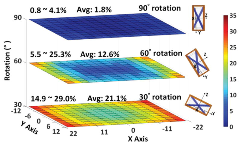
Measured PTE of the proposed 4-coil inductive link when the headstage is swept across XY plane in the cage, at H = 8 cm, and rotated by (a) 30°, (b) 60°, and (c) 90° along X axis.
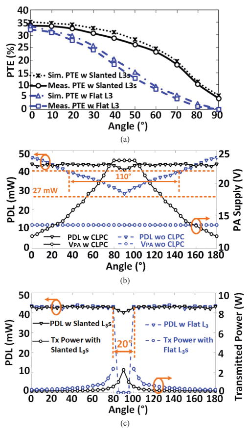
To validate the benefits of the proposed slanted Rx resonator design, particularly with respect to angular misalignments, in Fig. 12a, we have compared simulated and measured PTE results between the new slanted quad Rx resonators and the single flat resonator design in [29]. The PTE of the proposed 4-coil inductive link is improved for every rotation angle, and the rate of PTE decline vs. angular misalignment has also slowed down. It should also be noted that the simulated and measured results are in very good agreement. In addition to the coil design for homogeneous coverage of the homecage volume, the CLPC dynamically adjusts the Tx power to ensure PDL > 40 mW under any lateral, height, and angular misalignments, below which level the BLE range drops below a minimum reliable data transmission distance of 65 cm. Fig. 12b presents the measured PDL and PA supply voltage as a function of rotation angular at H = 7 cm, comparing the performance of CLPC vs. open loop. Without CLPC, as the PDL drops under the 40 mW with rotation > 35° or < 145°, and we need to place the controller BLE antenna very close to the headstage to maintain connectivity with no interruption. With CLPC, however, the headstage receives stable power (> 40 mW) within the full range of 0°–180°. In Fig. 12c we have compared the PDL and Tx power between the new slant coil and flat design in [29] as a function of 0°–180° Rx rotation. The CLPC is active in both cases and delivers sufficient power to the new headstage up to the worst case 90° rotation by increasing the Tx power up to 2.3 W. The flat Rx resonator, on the other hand, fails to deliver sufficient power to the headstage at rotations > 80° despite the Tx power being maxed out at 2.5 W by the CLPC.
Fig. 12.
Headstage measurements in the middle of the homecage at H = 8 cm: (a) Comparison between PTE vs. rotation with proposed slanted L3s and flat L3 in [35]. (b) Comparison between PDL and PA supply voltage vs. rotation with and without CLPC. (c) Comparison between PDL and Tx power vs. rotation with proposed slanted L3s and flat L3 in [29] in CLPC.
C. In vivo Experiments
Fig. 13 shows the EnerCage-HC2 in vivo experimental setup. Our goal was to elicit a well-documented behavioral effect of deep brain stimulation (DBS) and observe the consistency of the outcome among three rats as a proof of system functionality in the field. Fig. 13b shows the EnerCage-HC2 controller implementation, including its custom-designed cape, which allows the user to control the EnerCage-HC2 system through Wi-Fi connection. Fig. 13c shows the GUI running on a PC, including a live video stream from a MS-Kinect®, allowing remote control of the EnerCage-HC2 system and behavioral monitoring of the animal [38].
Fig. 13.
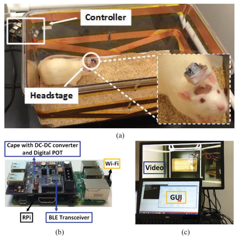
(a) In vivo experimental setup for 1-ch DBS in a freely behaving rat. (b) Close up view of the controller block including a custom-designed cape. (c) GUI running on a PC, including a live video stream from a MS-Kinect® for behavioral monitoring of the animal subject [38].
In vivo experiments were conducted with prior approval from the Institutional Animal Care and Use Committee (IACUC) at Emory University. We delivered a unilateral, charge-balanced, electrical stimulation to the GPi of three freely behaving rats. GPi is a major component of the basal ganglia, and is involved in the coordination of movement. Previous studies have reported that head turning behavior is a highly replicable behavioral effect induced by unilateral electrical stimulation of the GPi [39]–[42]. Hence, we expected to observe the same behavior using the EnerCage-HC2 system by stimulating the GPi wirelessly. Three 11-weeks old male Sprague Dawley rats, weighing 330–350 g, were implanted with a pair of monopolar stainless steel stimulating electrodes (MS303/1-AIU, Plastics One) targeting the right GPi (stereotaxic coordinates anteroposterior (AP) −0.8 mm; mediolateral (ML) +3.0 mm; dorsoventral (DV) −6.0 mm), one of which was an uninsulated stainless steel ground wire, wrapped around a skull screw. Impedance of the stimulation electrodes were 12.5 Ωk for rat 1, 7 Ωk for rat 2, and 6.5 Ωk for rat 3. The placement of the electrode tip in GPi was confirmed by subsequent histological processing of the subjects’ brain tissue, as shown in Fig. 14.
Fig. 14.
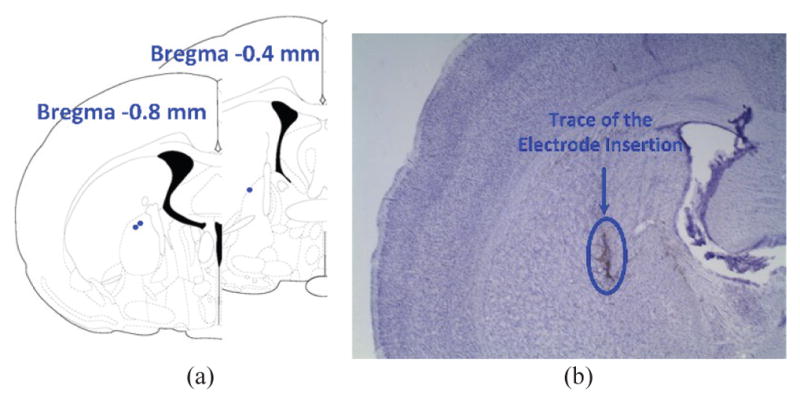
Electrode placement and Histology. (a) The red dots represent placement of the tip of the electrodes, all in the GPi. (b) Sample brain slice, stained with Nissl staining. The dark track in the center of the picture is the trace of the electrode insertion in the brain.
Each stimulation experiment was performed after two weeks of post-surgical recovery. Prior to the start of each experiment, the rats were handled for three days to acclimatize them to handling. At the start of the experiment, the rats were habituated to the homecage for 4 minutes, after which six 2-minute experiments were conducted. During the first minute of each experiment a sham stimulation was applied at minutes 1, 3, 5, 7, 9, and 11. Within the last 5 s of each experiment, the headstage delivered electrical stimulation to the test subject at the beginning of minutes 2, 4, 6, 8, 10, and 12. We also measured the animal head rotation during the first 10 s of each one-minute segment. Fig. 15a shows a current-controlled 5 s burst of stimulus pulses that delivers current of 225 μA and 75 μA in cathodic and anodic phases, respectively, at a rate of 40 Hz. To ensure charge balancing, stimulation current in the cathodic phase was 3x larger than the anodic phase, and the pulse width of in anodic phase (300 μs) was accordingly 3x longer than the cathodic phase (100 μs), as shown in Fig. 15b.
Fig. 15.
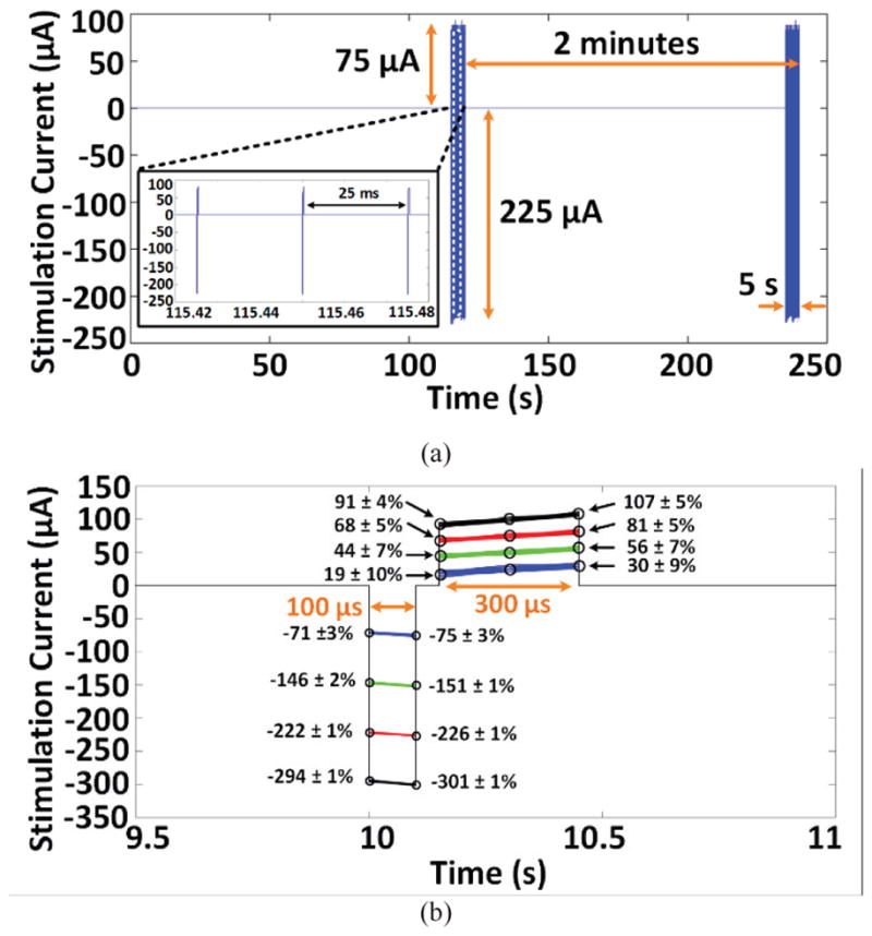
(a) Stimulation pulses in trial # 1 and # 2 of rat #3, acquired by decoding the data transmitted from the headstage via BLE while the animal was freely moving in the homecage. (b) Time-aligned stimulation pulses in trial #1.
To evaluate the accuracy of stimulus pulses in terms of current amplitude, we overlapped the acquired samples from current sensing resistors in Fig. 3b during the 5 s stimulation period of trial 1. Fig. 15b shows the acquired samples from time-aligned stimulation pulses at four current levels over a 1.5 ms window. The mean error between the desired and measured stimulus amplitudes at each sampling point is smaller than 10%, which verifies the stability and accuracy of the stimulation current. Expectedly, minimum stimulation current of 75 μA in the cathodic phase, which generates the lowest current sense voltage detected by the MCU built-in ADC, results in the highest mean error of 10%.
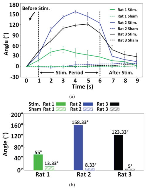
Consistent with previous studies [39]–[42], head turning behavior was clearly observed on all three rats during wireless stimulation periods. The head rotation angle (HRA) is defined as the angle between two straight lines, one connecting the base of rat tail to a point between ears to the tip of nose, as shown in Fig. 16, comparing rat 3 head movements before, during, and after a 5 s episode of the actual and sham stimulations. Fig. 17a shows the changes in HRA over time, with respect to the baseline angle at each stimulation onset for each rat for 6 actual and 6 sham stimulations. In Fig. 17b, a significant effect of stimulation was observed by comparing the maximum rotation angle to sham stimulation using one-tail paired t-test with P = 0.04. The rotation angle of rat 1 during stimulation period was smaller than both rat 2 and rat 3, which could be attributed to the larger impendence value of the stimulation electrode implanted in rat 1, compared to rats 2 and 3.
Fig. 16.
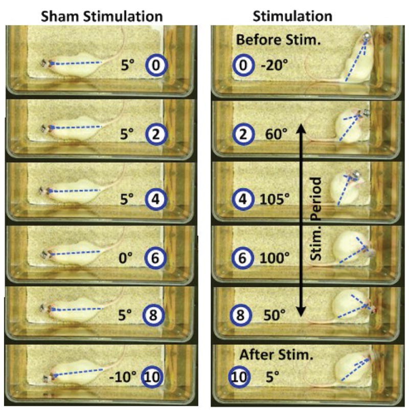
Comparing head turning behavior within 10 s between the actual and sham stimulations in rat 3. The relative time before, during, and after stimulation is indicated in seconds in the blue circle in each frame with the measured head turning angle next to it.
Fig. 17.
(a) Head rotation angle vs. time during actual stimulation in comparison with 9 s at the end of the 1st minute of a trial as control. (b) The mean maximum head rotations of each rat during actual and sham stimulations.
Fig. 18 shows the measured VDD and VPA during two trials on rat 3. The EnerCage-HC2 continuously delivers ~43 mW to the headstage by maintaining VDD within a user-defined voltage range, which is made possible by dynamically adjusting VPA and consequently the PA output power as a result of transmitting VDD samples to the controller at a rate of 100 Hz via BLE. The magnified segments of Fig. 18 show VDD variations during stimulations, which lead to severe coil misalignments due to animal head rotation. The CLPC mechanism has succeeded in maintaining 5 V < VDD < 5.4 V, indicated by horizontal red lines, by automatically increasing VPA from 12 V up to ~22 V to compensate for the disturbance. Following stimulations, when the subject’s head position returns back to normal, VPA is automatically decreased to prevent excessive Tx power transmission. To compensate for the change in the location of the subject’s head after stimulation, the VPA voltage has settled at a new level of 17 V.
Fig. 18.
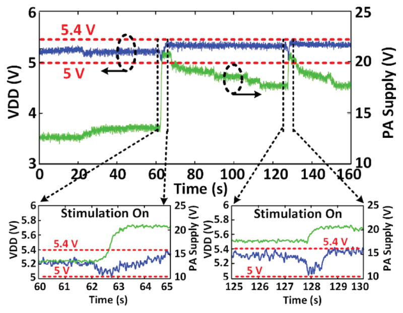
Voltage doubler output (VDD) and PA supply voltage (VPA) variations during a 5 s stimulation episode in trial #1 and #2, showing the VDD staying within a user-defined window, thanks to CLPC, despite head rotation and load variation during stimulation.
V. Conclusion
A wireless research instrument for conducting behavioral research on small freely behaving animals has been presented, which is robust and fully compatible with dimensions of standard homecage used in animal research facilities. The EnerCage-HC2 system can not only wirelessly energize but also communicate with a variety of sensors, actuators, and other electronic devices that are attached to or implanted in the animal body, while creating an enriched environment close to their natural habitat. EnerCage-HC2 benefits from: 1) a novel geometrically-optimized array of Rx coils for harvesting EM power for the headstage at any arbitrary positions or orientations within the homecage, 2) an array of strategically positioned High-Q segmented Tx coils, made of copper foils, that can create a homogeneously EM powered space across the entire homecage, 3) a robust communicating network based on Wi-Fi, UART, and BLE links, realizing remote control and data acquisition from the headstage, and 4) a CLPC mechanism ensuring stable power delivery to the headstage at minimum necessary Tx power. We have verified functionality of the EnerCage-HC2 system in vivo for wireless DBS by targeting the right GPi in three freely behaving rats, eliciting a distinct, well-documented, and very consistent behavior, involving quantified head rotation, while recording the actual stimulus current level and measures of transmitted and received power.
Acknowledgments
This work is supported in part by NSF awards ECCS-1407880 and ECCS-1408318, and NIH award 1R21EB018561.
Contributor Information
Yaoyao Jia, GT-Bionics lab, School of Electrical and Computer Engineering, Georgia Institute of Technology, Atlanta, GA 30308, USA.
S. Abdollah Mirbozorgi, GT-Bionics lab, School of Electrical and Computer Engineering, Georgia Institute of Technology, Atlanta, GA 30308, USA.
Zheyuan Wang, GT-Bionics lab, School of Electrical and Computer Engineering, Georgia Institute of Technology, Atlanta, GA 30308, USA.
Chia-Chun Hsu, Department of Physiology, Emory University, Atlanta, GA 30329, USA.
Teresa E. Madsen, Department of Physiology, Emory University, Atlanta, GA 30329, USA
Donald Rainnie, Department of Physiology, Emory University, Atlanta, GA 30329, USA.
Maysam Ghovanloo, GT-Bionics lab, School of Electrical and Computer Engineering, Georgia Institute of Technology, Atlanta, GA 30308, USA.
References
- 1.Grill WM, Norman SE, Bellamkonda RV. Implanted neural interfaces: biochallenges and engineered solutions. Annual review of biomedical engineering. 2009 Aug;11:1–24. doi: 10.1146/annurev-bioeng-061008-124927. [DOI] [PubMed] [Google Scholar]
- 2.Donoghue JP. Bridging the brain to the world: a perspective on neural interface systems. Neuron. 2008 Nov;60:511–521. doi: 10.1016/j.neuron.2008.10.037. [DOI] [PubMed] [Google Scholar]
- 3.Aravanis AM, et al. An optical neural interface: in vivo control of rodent motor cortex with integrated fiberoptic and optogenetic technology. Journal of neural engineering. 2007 Jun;4:S143. doi: 10.1088/1741-2560/4/3/S02. [DOI] [PubMed] [Google Scholar]
- 4.Shaw FZ, Lai CJ, Chiu TH. A low-noise flexible integrated system for recording and analysis of multiple electrical signals during sleep–wake states in rats. Journal of neuroscience methods. 2002 Jul;118:77–87. doi: 10.1016/s0165-0270(02)00146-2. [DOI] [PubMed] [Google Scholar]
- 5.Rossi MA, Go V, Murphy T, Fu Q, Morizio J, Yin HH. A wirelessly controlled implantable LED system for deep brain optogenetic stimulation. Frontiers in Integrative Neuroscience. 2015 Feb;9:8. doi: 10.3389/fnint.2015.00008. [DOI] [PMC free article] [PubMed] [Google Scholar]
- 6.Hashimoto M, Hata A, Miyata T, Hirase H. Programmable wireless light-emitting diode stimulator for chronic stimulation of optogenetic molecules in freely moving mice. Neurophotonics. 2014 May;1:011002–011002. doi: 10.1117/1.NPh.1.1.011002. [DOI] [PMC free article] [PubMed] [Google Scholar]
- 7.Lee ST, Williams PA, Braine CE, Lin DT, John SW, Irazoqui PP. A miniature, fiber-coupled, wireless, deep-brain optogenetic stimulator. IEEE Transactions on Neural Systems and Rehabilitation Engineering. 2015 Jan;23:655–664. doi: 10.1109/TNSRE.2015.2391282. [DOI] [PubMed] [Google Scholar]
- 8.Turcotte GG, Dufresne Camaro C-O, Kisomi AA, Ameli R, Gosselin B. A wireless optogenetic headstage with multichannel electrophysiological recording capability. Proc IEEE Sensors Conf. 2015 Sep;15:22776–22797. doi: 10.3390/s150922776. [DOI] [PMC free article] [PubMed] [Google Scholar]
- 9.Miranda H, Gilja V, Chestek CA, Shenoy KV, Meng TH. HermesD: a high-rate long-range wireless transmission system for simultaneous multichannel neural recording applications. IEEE Trans Biomed Circuits Sys. 2010 May;4:181–191. doi: 10.1109/TBCAS.2010.2044573. [DOI] [PubMed] [Google Scholar]
- 10.Szuts TA, et al. A wireless multi-channel neural amplifier for freely moving animals. Nature neuroscience. 2011 Jan;14:263–269. doi: 10.1038/nn.2730. [DOI] [PubMed] [Google Scholar]
- 11.Wurbel H. Ideal homes? housing effects on rodent brain and behaviour. Trends in Neuroscience. 2001 Apr;24:207–211. doi: 10.1016/s0166-2236(00)01718-5. [DOI] [PubMed] [Google Scholar]
- 12.Simpson J, Kelly J. The impact of environmental enrichment in laboratory rats-behavioural and neurochemical aspects. Behavioural Brain Research. 2011 Sep;222:246–264. doi: 10.1016/j.bbr.2011.04.002. [DOI] [PubMed] [Google Scholar]
- 13.Kempermann G, Kuhn HG, Gage FH. More hippocampal neurons in adult mice living in an enriched environment. Nature. 1997 Apr;386:493–495. doi: 10.1038/386493a0. [DOI] [PubMed] [Google Scholar]
- 14.Belayev A, et al. Enriched environment delays the onset of hippocampal damage after global cerebral ischemia in rats. Brain research. 2003 Feb;964:121–127. doi: 10.1016/s0006-8993(02)04089-1. [DOI] [PubMed] [Google Scholar]
- 15.Brauner A, Kurjiaka D, Ibragimov A, Baldwin A. Imapct of cage size and enrichment (tube and shelf) on heart rate variability in rats. Science. 2010;37 [Google Scholar]
- 16.Wentz CT, Bernstein JG, Monahan P, Guerra A, Rodriguez A, Boyden ES. A wirelessly powered and controlled device for optical neural control of freely-behaving animals. Journal of neural engineering. 2011 Jun;8:046021. doi: 10.1088/1741-2560/8/4/046021. [DOI] [PMC free article] [PubMed] [Google Scholar]
- 17.Yeh AJ, Ho JS, Tanabe Y, Neofytou E, Beygui RE, Poon AS. Wirelessly powering miniature implants for optogenetic stimulation. Applied Physics Letters. 2013 Oct;103:163701. [Google Scholar]
- 18.Park SI, et al. Soft, stretchable, fully implantable miniaturized optoelectronic systems for wireless optogenetics. Nature biotechnology. 2015 Nov;33:1280–1286. doi: 10.1038/nbt.3415. [DOI] [PMC free article] [PubMed] [Google Scholar]
- 19.Lee SB, Lee B, Kiani M, Mahmoudi B, Gross R, Ghovanloo M. An inductively-powered wireless neural recording system with a charge sampling analog front-end. IEEE Sensors Journal. 2016 Jan;16:475–484. doi: 10.1109/JSEN.2015.2483747. [DOI] [PMC free article] [PubMed] [Google Scholar]
- 20.Jow U, McMenamin P, Kiani M, Manns J, Ghovanloo M. EnerCage: a smart experimental arena with scalable architecture for behavioral experiments. IEEE Trans Biomed Eng. 2014 Jan;61(1):139–148. doi: 10.1109/TBME.2013.2278180. [DOI] [PMC free article] [PubMed] [Google Scholar]
- 21.Kilinc E, Conus G, Weber C, Kawkabani B, Maloberti F, Dehollain C. A system for wireless power transfer of micro-systems in-vivo implantable in freely moving animals. IEEE Sensors Journal. 2014 Feb;14(2):522–531. [Google Scholar]
- 22.Lee B, Kiani M, Ghovanloo M. A smart wirelessly powered homecage for long-term high-throughput behavioral experiments. IEEE Sensors Journal. 2015 Sep;15(9):4905–4916. doi: 10.1109/JSEN.2015.2430859. [DOI] [PMC free article] [PubMed] [Google Scholar]
- 23.Mirbozorgi SA, Bahrami H, Sawan M, Gosselin B. A smart cage with uniform wireless power distribution in 3D for enabling long-term experiments with freely moving animals. IEEE Trans Biomed Circuits Sys. 2016 Apr;10:424–434. doi: 10.1109/TBCAS.2015.2414276. [DOI] [PubMed] [Google Scholar]
- 24.Carta R, Tortora G, Thone J, Lenaerts B, Valdastri P, Menciassi A, Dario P, Puers R. Wireless powering for a self-propelled and steerable endoscopic capsule for stomach inspection. Biosensors and Bioelectronics. 2009;25:845–851. doi: 10.1016/j.bios.2009.08.049. [DOI] [PubMed] [Google Scholar]
- 25.Millard RE, Shepherd RK. A fully implantable stimulator for use in small laboratory animals. J neuroscience methods. 2007 Nov;166:168–177. doi: 10.1016/j.jneumeth.2007.07.009. [DOI] [PMC free article] [PubMed] [Google Scholar]
- 26.Lee B, Ahn D, Ghovanloo M. Three-phase time-multiplexed planar power transmission to distributed implants. Journal of Emerging and Selected Topics in Power Electronics. 2016;4(1):263–272. doi: 10.1109/JESTPE.2015.2436391. [DOI] [PMC free article] [PubMed] [Google Scholar]
- 27.Choi BH, Lee ES, Sohn YH, Jang GC, Rim CT. Six degrees of freedom mobile inductive power transfer by crossed dipole Tx and Rx coils. Transactions on Power Electronics. 2016;31(4):3252–3272. [Google Scholar]
- 28.Alternative Design Manufacturing & Supply. Rat Plastic Cage [online] 2016 Available at: http://www.altdesign.com/products/animals/rat/rat-plastic-cage/
- 29.Mirbozorgi SA, Jia Y, Canales D, Ghovanloo M. A wirelessly-powered homecage with segmented copper foils and closed-loop power control. IEEE Transactions on Biomedical Circuits and Systems, to be published. 2016 doi: 10.1109/TBCAS.2016.2577705. [DOI] [PMC free article] [PubMed] [Google Scholar]
- 30.Kiani M, Ghovanloo M. An RFID-based closed-loop wireless power transmission system for biomedical applications. IEEE Transactions on Circuits and Systems II: Express Briefs. 2010 Apr;57:260–264. doi: 10.1109/TCSII.2010.2043470. [DOI] [PMC free article] [PubMed] [Google Scholar]
- 31.Vaughan JT, Griffiths JR. RF coils for MRI. John Wiley & Sons; 2012. [Google Scholar]
- 32.Sharma A, Zuazola IJG, Batchelor JC, Perallos A. Dual purpose near-and far-field UHF RFID coil antenna with non-uniformly distributed-turns. IEEE Antennas and Wireless Propagation Letters. 2015 Feb;14:1342–1345. [Google Scholar]
- 33.Tang SC, McDannold NJ. Power loss analysis and comparison of segmented and unsegmented energy coupling coils for wireless energy transfer. IEEE journal of emerging and selected topics in power electronics. 2015 Mar;3:215–225. doi: 10.1109/JESTPE.2014.2330951. [DOI] [PMC free article] [PubMed] [Google Scholar]
- 34.Kiani M, Ghovanloo M. A figure-of-merit for designing high- performance inductive power transmission links. IEEE Trans Industrial Electronics. 2013 Nov;60:5292–5305. doi: 10.1109/TIE.2012.2227914. [DOI] [PMC free article] [PubMed] [Google Scholar]
- 35.Zhong W, Lee CK, Hui SR. General analysis on the use of Tesla’s resonators in domino forms for wireless power transfer. IEEE Transactions on Industrial Electronics. 2013 Jan;60:261–270. [Google Scholar]
- 36.Gabriel S, Lau RW, Gabriel C. The dielectric properties of biological tissues: II. measurements in the frequency range of 10 Hz to 20 GHz. Phys Med Biol. 1996;41:2251–2269. doi: 10.1088/0031-9155/41/11/002. [DOI] [PubMed] [Google Scholar]
- 37.W Federal Communications Commission. Specific Absorption Rate (SAR) for Cellular Telephones [online] 2011 Available at: https://www.fcc.gov/general/specific-absorption-rate-sar-cellular-telephones.2013.
- 38.Wang Z, Mirbozorgi SA, Ghovanloo M. Towards a Kinect-based behavior recognition and analysis system for small animals. Proc IEEE Biomedical Circuits and Systems Conf. 2015 Oct;:683–686. [Google Scholar]
- 39.Kelland MD, Asdourian D, Kelland DZ. Inhibition and excitation of neck and shoulder muscles during unilateral electrical stimulation of the rat neostriatum. Behavioural Brain Research. 1988 Sep;30:1–13. doi: 10.1016/0166-4328(88)90002-2. [DOI] [PubMed] [Google Scholar]
- 40.Aiko Y, Hosokawa S, Shima F, Kato M, Kitamura K. Alterations in local cerebral glucose utilization during electrical stimulation of the striatum and globus pallidus in rats. Brain Research. 1988 Feb;442:43–52. doi: 10.1016/0006-8993(88)91430-8. [DOI] [PubMed] [Google Scholar]
- 41.Asdourian D, Lentz S, Kelland M. Motor effects of globus pallidus stimulation in the rat: lesions to corticofugal fibers block the motor effects. Behavioural Brain Research. 1991 Aug;44:185–193. doi: 10.1016/s0166-4328(05)80023-3. [DOI] [PubMed] [Google Scholar]
- 42.Lee L, Slater P. Role of globus pallidus and substantia nigra efferent pathways in striatally evoked head turning in the rat. Experimental Brain Research. 1981 Oct;44:170–176. doi: 10.1007/BF00237338. [DOI] [PubMed] [Google Scholar]


