Abstract
Since shape memory alloy (SMA) has high power density and is magnetic resonance imaging (MRI) compatible, it has been chosen as the actuator for the meso-scale minimally invasive neurosurgical intracranial robot (MINIR-II) that is envisioned to be operated under continuous MRI guidance. We have devised a water cooling strategy to improve its actuation frequency by threading a silicone tube through the spring coils to form a compact cooling module-integrated actuator. To create active bi-directional motion in each robot joint, we configured the SMA springs in an antagonistic way. We modeled the antagonistic SMA spring behavior and provided the detailed steps to simulate its motion for a complete cycle. We investigated heat transfer during the resistive heating and water cooling processes. Characterization experiments were performed to determine the parameters used in both models, which were then verified by comparing the experimental and simulated data. The actuation frequency of the antagonistic SMAs was evaluated for several motion amplitudes and we could achieve a maximum actuation frequency of 0.143 Hz for a sinusoidal trajectory with 2 mm amplitude. Lastly, we developed a robotic system to implement the actuators on the MINIR-II to move its end segment back and forth for approximately ±25°.
Keywords: Medical robotics, MINIR-II, neurosurgery, high frequency actuator, smart material, NiTiNOL, shape memory alloy (SMA) spring, cooling modules
1 Introduction
Brain tumor is one of the leading causes of cancer deaths in the US (American Brain Tumor Association, 2015) and has a significant effect on the quality of life of an individual. Since magnetic resonance imaging (MRI) provides excellent soft-tissue contrast, we envision a combination of continuous MRI modality and a dexterous meso-scale robot with electrocauterization capability can lead to potentially real-time MRI-guided neurosurgical procedure. It will be more desirable than the current intraoperative MRI-guided surgery involving switching of either the patient or the machine between the MRI room and the operation room in a specially-designed surgical theatre (Spectrum Health, 2015). The possibility of employing an MRI-compatible robot for neurosurgery (Ho and Desai, 2013) that is low-cost and potentially disposable after single use, requires the development of an MRI-compatible actuator, whereby the actuator can be controlled at a sufficiently higher frequency.
MRI compatible actuation methods include pneumatic actuation (Yang et al., 2013), hydraulic actuation (Kim et al., 2002), piezoelectric actuation (Wang et al., 2009), and shape memory alloy (SMA)-based actuation (Ho et al., 2015). Pneumatic system is safe, clean, and easy to implement but the noise and bulkiness of the system, and the difficulty in achieving smooth motion make it unsuitable for a meso-scale robot for neurosurgery. Hydraulic system can provide steady transmission, significant force and large range of displacement (Kim et al., 2002). However, it poses the risk of cavitation and fluid leakage. Piezoelectric motors are used in MRI environments due to its high precision and reliability in performance. However, high cost of piezomotors coupled with the requirement of multiple motors for a multi-DOF robotic system could make it cost prohibitive. Hence, in our current work, we have focused on developing a neurosurgical robot with SMA actuators.
SMA has been researched in the past thirty years with various constitutive models being proposed to simulate its behavior and improve its control. Creative applications have made use of the SMA’s shape memory effect and superelastic behavior in various geometric forms such as wires (Tamai and Kitagawa, 2002), strips (Lagoudas et al., 1997), rods (Thompson and Griffin, 1993), films (Krulevitch et al., 1996), springs (Kim et al., 2014) and tubes (Ng and Sun, 2006). Both academia and industry have made use of the SMA’s inherent properties such as lightweight, low-cost and high power density in several product applications. Additive manufacturing, such as selective laser sintering (SLS) and electron beam melting (EBM), also allows the production of porous NiTi structures which are used as implants in orthopedic surgery (Elahinia et al., 2012). The low cost involved in developing an SMA actuator allows the product to be disposable, leading to increased interest from the medical and industrial communities. Despite the multiple advantages of the SMA, there are a few drawbacks that need to be addressed so that the SMA can be fully taken advantage of as an actuator for a neurosurgical robot. These include the non-linear properties during phase transformation, the effect of thermomechanical cycles on the resultant stress and strain, and most importantly the slow actuation speed due to the low cooling rate under natural cooling by the surrounding air. A cooling strategy is required to transform the SMA from its heated austenite phase to the martensite phase at room temperature as soon as possible, so as to improve its actuation speed in an antagonistic setup.
The minimally invasive neurosurgical intracranial robot (MINIR) project began with the vision of developing a meso-scale neurosurgical robot with multiple degrees of freedom to remove brain tumor under continuous MRI guidance. In our initial work, we developed a brass alloy 360 MINIR prototype with nine revolute joints, each of which was actuated by antagonistic SMA wires (Ho et al., 2011, 2012). This is followed by a rapid prototyped MINIR actuated by tendon-sheath mechanism (Ho and Desai, 2012; Ho et al., 2015). We are currently investigating a tendon-driven spring-based continuum robot, namely MINIR-II, to improve the compactness and dexterity of the robot during neurosurgery (Cheng et al., 2015, In Press; Kim et al., 2015; Kim and Desai, 2015). The robot has an inner spring backbone that is divided into three segments and a continuous outer spring to maintain the rigidity and shape of the robot. Each segment has two degrees of freedom (DoFs) (i.e. pitch and yaw), actuated by two pairs of antagonistic SMA springs via tendons.
The MINIR-II robot uses electrocautery to coagulate the brain tumor which can then be aspirated. Generally, an electrocauterization procedure in neurosurgery is carried out at a relatively slow pace. The linear piezoelectric actuator on the ROBOCAST system advances the biopsy probe at a velocity of 2 mm/s (Comparetti et al., 2011). The neuroArm, also actuated by piezoelectric motors, has a tip speed of 0.5–5 mm/s (Louw et al., 2004). In a robot-assisted ventriculostomy, the endoscope is moved at speeds between 0.5–2 mm/s (Zimmermann et al., 2004). A piezoelectric-motor actuated needle designed for neurosurgery was inserted and manipulated at speeds between 0.5–2 mm/s and it was found that an increase in speed would increase resistant force but reduce tissue deformation (De Lorenzo et al., 2011). It is important to recognize that the actuation frequency of the piezoelectric motor can reach thousands of Hz but it is not required during neurosurgery. We can conclude that both the movement speed of a cautery probe in brain tissue and the speed of electrocauterization process are in the range between 0.5 and 5 mm/s. Therefore, we want to make sure that our neurosurgical robot actuated by the SMA springs has sufficient frequency available to the surgeon during the surgery.
Several SMA cooling methods such as fan cooling (Lewis et al., 2013), water-jet cooling (Zhang et al., 2008), mobile heat sink (Russell and Gorbet, 1995), Peltier effect (Luo et al., 2000; Selden et al., 2004) and wet actuator (Ertel and Mascaro, 2010) have been proposed in the literature. The water-jet cooling of a moving SMA was investigated to explore its potential use in the field of microelectromechanical system (MEMS) and it was found that the shape deformation of the actuator increases with increased jet speed and decreases with increased nozzle-to-surface distance (Zhang et al., 2008). Peltier effect was also used to create an SMA actuator with high frequency response. The SMA wire cooled down within 1s (0.5 A current supplied) to 3s (1.5 A current supplied) after getting heated for 1s (Luo et al., 2000). A mobile heat sink with an innovative friction clutch mechanism was developed without an increase in energy loss or power consumption (Russell and Gorbet, 1995). Media such as compressed air (Kim et al., 2014), thermal grease (Loh et al., 2006; Pathak et al., 2008) and water (Ertel and Mascaro, 2010; Pathak et al., 2008) have also been used for various research involving SMA wires and springs. However, a compact design that integrates the cooling mechanism with the SMA is still not available. The focus of this paper is to address this particular shortcoming by building upon the wet actuator concept (Ertel and Mascaro, 2010) of using water as the cooling medium and applying it to the SMA spring instead of the SMA wire. We are able to maintain the compactness of the spring actuator through routing of a soft tube over each spring coil. Electrical heating is used to actuate the SMA spring so that power is not wasted on maintaining the hot water temperature in a wet actuator system.
The paper is divided into several sections: Section 2 introduces the cooling module integrated with the SMA spring to improve the SMA actuation frequency through forced convection. Section 3 discusses the derivation of the phenomenological model for antagonistic SMA springs and the characterization experiments to determine the model parameters. Section 4 discusses the heat transfer model during the heating and cooling processes of the SMA spring wire as well as the characterization experiments to determine various thermal parameters. In section 5, we discuss two different experimental setups to evaluate the behavior and performance of antagonistic SMA springs, and implement the actuators on MINIR-II. Section 6 presents the simulation steps and result of antagonistic SMA spring behavior, and the simulation result of the heat transfer model. We also discuss the actuation frequency of the SMA springs and implementation of the actuators on MINIR-II. Finally, in section 7, we summarize our work and provide insights into related future works.
2 Design of an SMA Spring Cooling Module
The wet SMA actuator introduced by Ertel and Mascaro (Ertel and Mascaro, 2010) was an SMA wire placed in a compliant tube that changed its longitudinal shape with the SMA when it was heated by flowing hot water through the tube (Ertel and Mascaro, 2010). Cold water was then passed through the tube to cool the SMA wire. Similarly, our proposed cooling strategy uses water as the cooling medium. The main design objectives of our cooling strategy for the SMA springs are to improve the available actuation frequency of the SMA spring, and to maintain the compactness and portability of the actuator. Therefore, we proposed a flexible channel that consists of a soft silicone tube being threaded carefully through each SMA spring coil, forming a compact SMA spring with integrated cooling module (Cheng and Desai, 2015), as shown in Figure 1(a). Other materials needed in making the cooling-module integrated SMA actuator are shown in Figure 1(b), including two moisture-resistant Acetal Barbed Tube Tee Fitting for tube ID (McMaster Carr, USA), two silicone rubber tapered stopper plugs (Powder Plug Coating Supply, USA) with dimensions of 1.5mm bottom diameter × 4.7mm top diameter × 15.8mm long, and a micro resistance temperature detector (RTD) (Alpha Technics, CA, USA). Before the threading process started, we straightened the two ends of the spring to allow easy entry of spring wire into the tube. The length of each straightened end is about 35 mm. The RTD sensor was then tied to one of the SMA spring coils using a thin strip of wire and bonded to the surface using high-temperature resistant superglue. Two pieces of electrical wires were soldered using tin solder with high percentage of silver to the last SMA spring coils, respectively, before the two straight ends of the SMA spring inside the tube. This ensures that the straight ends would not curve into a helical shape when current was applied. Sharp ends of the spring were trimmed and made blunt to prevent cracks from forming in the generally thin tube while the tube was being threaded.
Figure 1.
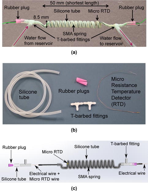
(a) SMA spring coils covered in a continuous silicone tube (b) Materials needed to make the SMA spring with cooling module (c) CAD schematic of the cooling module-integrated SMA spring with detailed illustration of the connection and arrangement of each component
Once the SMA spring was completely wrapped in the tube, T-barbed fittings were connected to the tube at both its ends. The fittings were sealed using rubber plugs, through which the straight ends of the SMA spring were inserted. Electrical wires were threaded through the rubber plugs using a needle to prevent any water leakage and led to the circuit board. Strong fish wires acting as tendons were connected mechanically to the two ends of the straight sections of the spring during the experiments. Figure 1 shows a magnified view of the SMA spring actuator integrated with the cooling channel.
3 Phenomenological Model of SMA Spring in an Antagonistic Configuration
3.1 SMA constitutive model
In antagonistic actuation configuration, the SMA spring actuator can be coupled with either a passive spring or another SMA spring. In the current work, we used a pair of SMA springs to allow the neurosurgical robot to begin at the home (center) position and perform back and forth motion. A constitutive model representing the behavior of the SMA springs in antagonistic configuration is therefore required to predict the actual motion which can then be used in a control framework. Through the model, we are able to obtain a relationship between the applied axial force, axial deflection and martensite volume fraction around the SMA transformation temperatures obtained from the heat transfer model in section 4. The state variables in our model are therefore axial force (F), axial spring deflection (δ), and martensite volume fraction (ξ). Tanaka (Tanaka, 1986), Liang and Rogers (Liang and Rogers, 1990), Brinson (Brinson, 1993), Boyd and Lagoudas (Boyd and Lagoudas, 1996), and Frémond (Frémond, 1996) initially proposed constitutive models for SMA wire. Tobushi and Tanaka (Tobushi and Tanaka, 1991), Liang and Rogers (Liang and Rogers, 1997), Aguiar et al. (Aguiar et al., 2010), Hadi et al. (Hadi et al., 2010), and Ma et al. (Ma et al., 2013) used the wire models to derive those for the SMA helical spring. An et al. (An et al., 2012) also proposed a static two-state design model for the SMA spring.
The model described here is built on Brinson’s work on SMA wire (Brinson, 1993) and the work by Ho and Desai (Ho and Desai, 2013; Ho et al., 2015), which was based on Tobushi and Tanaka’s (Tobushi and Tanaka, 1991), and Liang and Roger’s (Liang and Rogers, 1997) models. As stated in the work of Aguiar et al. (Aguiar et al., 2013), Brinson model was originally used for describing one-dimensional tension and compression and it would be valid to describe pure shear stress of an SMA spring by replacing the tensile properties with the shear properties. This is due to the fact that the torsion test has generated qualitatively similar stress-strain curve as the tension test (Manach and Favier, 1997; Jackson et al., 1972). Even though there are previous works (McNaney et al., 2003; Thamburaja and Anand, 2002) that show opposite results for SMA in the superelastic regime, it has generally been accepted in a significant amount of literature (Liang and Rogers, 1997; Yates and Kalamkarov, 2013; Tobushi and Tanaka, 1991; Aguiar et al., 2013; de Sousa and Junior, 2014) that Eq. (1) is an appropriate constitutive model for an SMA spring. The governing equation in terms of shear stress in the SMA spring is expressed as (Liang and Rogers, 1997):
| (1) |
where τ,G,γ,Θ,T,Ω, and ξ are shear stress, shear modulus, shear strain, coefficient of thermal expansion, temperature, phase transformation coefficient and martensite volume fraction, respectively. Subscript ‘0’ denotes the initial conditions. In this work, we assume that the coefficient of thermal expansion, Θ, is negligible because of the relatively unsubstantial thermal strain compared to the strain due to phase transformation.
Ignoring the pitch and curvature effect, and assuming that the shear strain is linearly distributed in the spring wire cross section, the spring coil diameter is constant throughout the spring length, and phase transformation is homogeneous across the spring wire cross section, shear strain can be related to axial spring deflection by the following expression (Shigley, 1972):
| (2) |
where ds, Ds and N are the SMA spring wire diameter, mean diameter of the spring, and the number of spring coils, respectively. Assuming that phase transformation is homogeneous along the SMA spring wire cross section, the maximum shear stress at the outer surface of the SMA spring wire, τmax = τ, can be related to axial force by the following expression (Aguiar et al., 2013; Liang and Rogers, 1997; Shigley, 1972):
| (3) |
where Wc is the Wahl’s correction factor . Shear stress is linearly distributed across the spring wire cross section when Wc is unity. Substituting Eqs. (2) and (3) into Eq. (1) leads to
| (4) |
where and . It should be noted that the homogeneous phase transformation assumption is not the most realistic representation of the shear stress and phase distribution in the SMA spring wire cross section. However, it is useful to be employed in a simplified modeling approach to simulate the antagonistic SMA behavior in a practical robotic actuation setup. Models with more realistic non-homogeneous phase distribution in different annular regions of the SMA cross section have been proposed and investigated in the literature (Tobushi and Tanaka, 1991; Aguiar et al., 2010; Bucchi et al., 2014; de Sousa et al., 2016).
By applying a material restriction, we can form a relationship between the shear modulus and the phase transformation coefficient (Brinson, 1993). We consider a case where an SMA spring in its fully austenite state (no initial deflection) is loaded until all the austenite is converted into detwinned martensite. The deflection that remains upon unloading is assumed to be the maximum recoverable deflection, δL. In this scenario, the initial conditions are F0 = δ0 = ξ0 = 0 and the final conditions are F = 0, δ = δL, ξ = 1. Replacing these variables in Eq. (4) leads to the relationship:
| (5) |
Substituting Eq. (5) into Eq. (4), we obtain
| (6) |
The shear modulus can be expressed as (Brinson, 1993; Tanaka, 1986):
| (7) |
where GM and GA are the elastic shear moduli of temperature-induced martensite and austenite, respectively. Brinson proposed that martensite volume fraction, ξ, that varies from 0 to 1, consists of two components: twinned martensite or temperature-induced martensite (TIM), ξT, and detwinned martensite or stress-induced martensite (SIM), ξS (Brinson, 1993), and hence:
| (8) |
Having gone through the derivation in Brinson’s work (Brinson, 1993), we can express the constitutive model of an SMA spring that relates the axial force on the spring, F, and the spring deflection, δ, as:
| (9) |
Based on Eq. (9), we can differentiate between twinned and detwinned martensite phases, and thus take into account the non-linear stress-strain behavior for the entire temperature range. We assume that the tendon that connects the SMA springs is always in tension and any stretch in the tendon is negligible.
We observed, through our characterization experiment, that an SMA spring, in its martensite phase, has a distinct force-deflection relationship. It can be divided into a linear region for and a non-linear transformation region for , where and are critical start shear stress and critical finish shear stress, respectively. GM is the shear modulus of the SMA spring when it remains in the twinned martensite phase and behaves linearly like a passive tension spring within its elastic limit. The non-linear region is reflected in the Brinson model through the detwinned martensite volume fraction, ξS, that is modeled as a cosine function, ranging from 0 to 1 as the SMA martensite detwins.
When two SMA springs are configured antagonistically, and are heated and cooled alternately, we can model the force-deflection relationship as the non-heated SMA spring in its martensite phase getting stretched by the heated SMA spring during its actuation in either direction. We assume the starting position of the spring is always at or under the characteristic martensite graph. Therefore, we write the initial detwinned martensite volume fraction as follows:
| (10) |
We can then substitute Eq. (10) and the initial conditions for each heating and cooling process into Eq. (9) to obtain the equation governing each SMA in the antagonistic pair, in terms of force and displacement. More detailed descriptions of the steps taken to simulate the antagonistic SMA behavior will be discussed in Section 6: Results and Discussion.
Based on the above model, we need to know the change in martensite volume fraction of both the heated and non-heated SMAs. During the heating phase, martensite volume fraction components, ξS and ξT, are functions of temperature and shear stress and can be written as follows (Brinson, 1993):
| (11a) |
| (11b) |
| (11c) |
where CA is the martensite to austenite transformation constant. AF and AS are the austenite finish and austenite start temperatures, respectively. The martensite volume fraction of the non-heated spring that is stretched from twinned martensite to detwinned martensite can be expressed as follows (Brinson, 1993):
For T<MS and :
| (12a) |
| (12b) |
where, if MF<T<MS and T<T0
| (12c) |
| (12d) |
otherwise
| (12e) |
The change in martensite volume fraction of the originally heated spring that, upon cooling, transforms from austenite to detwinned martensite is given by:
| (13a) |
| (13b) |
where CM is the austenite to martensite transformation constant and MS is the martensite start temperature. Detailed work on how to determine both CM and CA will be described in subsection 3.2.
It is important to note that the spring does not transform into pure twinned martensite phase upon cooling because it is not cooled down in stress-free state. There is always stress from the antagonistic spring at all times.
3.2 Determination of parameters for the SMA spring constitutive model
All the parameters required for the SMA phenomenological model in Section 3.1 are listed in Table 1. The four stress-free transformation temperatures of the SMA were obtained from a differential scanning calorimetry (DSC) test, in which a small sample of 18 mg of the SMA was heated and cooled in the temperature range of 25 °C to 100 °C. The heat flow rate results obtained from the test is plotted in Figure 2. To determine the martensite and austenite shear moduli of the SMA spring, we stretched the SMA spring and obtained the relationship between force and displacement of the spring at T = 25 °C (T<AS) and T = 60 ° (T>AF). In both experiments, we fixed one side of the SMA spring to a force sensor (MDB-2.5, Transducer technology, USA) attached to a fixed wall and the other side to a DC motor load shaft, as shown in Figure 3. We used Proportional+Integral (PI) control to maintain the SMA temperature before actuating the motor to stretch the spring for 95 mm. The force and spring deflection data are shown in Figure 4(a), where analytical data from the SMA model were shown to match the experimental data. The force data was converted into shear stress using Eq. (3) while the displacement data was converted into shear strain using Eq. (2). Shear stress is then plotted against shear strain in Figure 4(b). Two lines of best fit were used to determine slopes in the linear regions during austenite and martensite phases. The critical shear stress for conversion of twinned martensite to detwinned martensite can be determined from the highest shear stress in the linear region of the characteristic martensite graph for T<AS, as shown in Figure 4(b).
Table 1.
SMA Spring Parameters
| Parameters | Symbols | Units | Values | |
|---|---|---|---|---|
| Number of spring coil | N | 13 | ||
| Wire diameter | ds | mm | 0.75 | |
| Spring diameter | Ds | mm | 8.5 | |
| Twinned martensite shear modulus | GM | GPa | 16.36 | |
| Austenite shear modulus | GA | GPa | 25.06 | |
| Austenite start temperature | AS | °C | 45.87 | |
| Austenite finish temperature | AF | °C | 49.12 | |
| Martensite start temperature | MS | °C | 42.37 | |
| Martensite finish temperature | MF | °C | 38.17 | |
| Martensite constant | CM | MPa/°C | 17.25 | |
| Austenite constant | CA | MPa/°C | 12.81 | |
| Critical start shear stress |
|
MPa | 69.25 | |
| Critical finish shear stress |
|
MPa | 164.8 | |
| Maximum recoverable deflection | δL | m | 0.08 |
Figure 2.
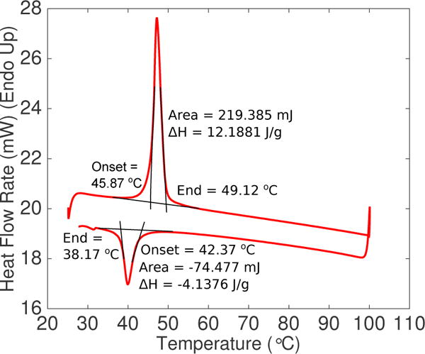
Transformation temperatures obtained from raw data of differential scanning calorimetry (DSC) test
Figure 3.
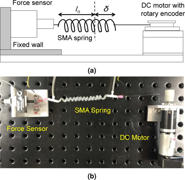
(a) Schematic and (b) actual experimental setup to stretch SMA spring at T <AS and T>AF (l0 is the initial non-stretched length of the SMA spring and δ is the axial deflection)
Figure 4.
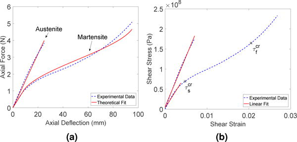
(a) Experimental and theoretical data comparison for T >AF (characteristic austenite graph) and for T <AS (characteristic martensite graph) (b) Experimental result and linear fit to determine the elastic shear moduli for T >AF, GA and for T <AS, GM
We performed block test at two different pre-stress levels to determine the transformation constants, CM and CA. The SMA spring was connected to a force sensor attached to a fixed wall on one side and to a moveable wall on the other side, as shown by the schematic in Figure 5(a). The wall was moved farther from the SMA spring to create the higher pre-stress level. During each of the two experiments, the two walls were fixed and hence the strain of the SMA spring was assumed zero. We first heated the SMA spring using a heat gun and once the force reached a plateau, the heat gun was removed and the SMA spring was left to cool down to room temperature. Force and temperature data were recorded throughout the experiment. We determined four transformation temperatures at each stress level from the force-temperature plot and connected two data points representing the same transformation temperature with a line. The four lines, as shown in Figure 5(b), represented the relationship between critical shear stress and each of the four transformation temperatures. They provided us with the constant, CM, which was the average of the slopes for the MS and MF lines and CA, which was the average of the slopes for the AS and AF lines.
Figure 5.
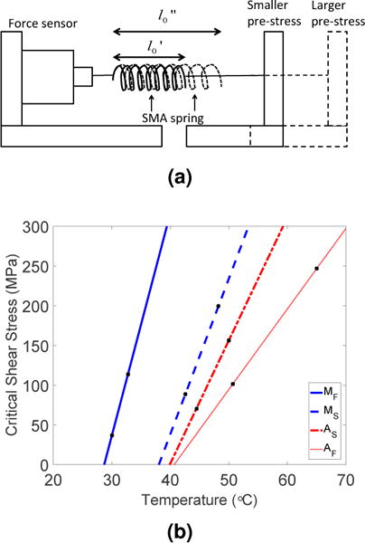
(a) Schematic of block test ( and represent two different initial lengths (prestrains) due to the two pre-stresses) (b) Experimental results from block tests done at 2 different pre-stresses (represented by the two markers on each line) for four transformation temperatures
4 Heat Transfer Modeling
4.1 Heat transfer model
SMA is a smart material that responds to temperature changes. In our work, we increased the temperature of the SMA springs using resistive heating and reduced it using forced convection of water. A thermal model is hereby developed to predict the temperature profile of SMA for the transient process. It can be combined with the SMA phenomenological model to simulate the SMA displacement during its actuation period.
We related the variation of temperature in the SMA spring wire with time under four assumptions. Firstly, heat is purely removed from the SMA into its environment via convection. When compared with the heat removed by forced convection, that removed via conduction and radiation is negligible and therefore is not considered significant. Secondly, Biot number, Bi, can be defined as follows:
| (14) |
where hw and ks are the convective heat transfer coefficient of water and thermal conductivity of SMA, respectively. If , then we can assume the resistance to conduction in the SMA is much smaller than the resistance to convection across its boundary layer with water. Using the convective heat transfer coefficient of water (discussed later in this paper), Biot number during forced convection ranges from 0.05 to 0.1 throughout the entire operational temperature range. Since Bi ≤ 0.1, we can apply the lumped capacitance method which assumes that the temperature within SMA is spatially uniform. Thirdly, geometrical changes in the radial direction is negligible during the heating and cooling process, leading to the assumption that SMA spring wire diameter stays unchanged at all times, including during phase transformation. Fourthly, material properties such as heat capacity, as well as temperature distribution are homogeneous throughout the entire spring length and across its cross-section. SMA resistance changes in a hysteretic form (Ma et al., 2004) during phase transformation but its negligible changes were not taken into account in our analysis.
In our model, we made use of a control volume of a small cylindrical section, Δx, of the SMA spring wire. In the subsequent discussion, subscript ‘s’ denotes the SMA wire and subscript ‘w’ denotes water in the coiled tube. Applying energy balance to the control volume (Bhattacharyya et al., 2002), the heat transfer model for the SMA spring wire can be represented as follows:
| (15) |
where βs,I,Ac,A,hw,Ts,Tw,Ls,ms and Cs are SMA resistivity, current, cross-sectional area of the SMA spring wire, surface area of the SMA spring wire, heat convection coefficient of water, surface temperature of SMA, water temperature, latent heat of transformation, mass of SMA, and the specific heat capacity of SMA, respectively.
The first term on the left side of Eq. (15) describes resistive heating using electric current. The second term refers to the heat transfer between the SMA wire and its fluid environment. The heat convection coefficient is smaller during heating because it only involves free convection. It increases during cooling due to forced convection. The third term describes the heat energy changes during phase transformation of SMA between martensite and austenite phases. Martensite volume fraction is a function of both temperature and shear stress. Its derivative is obtained by differentiating Eq. 11a and Eq. 13a for the heating and cooling phases, respectively. For the simulation, shear stress and its derivative were obtained and derived from the experimental force measured by the force sensor. The term on the right side of Eq. (15) represents the heat energy storage in the SMA control volume. Mass, surface area, and cross-sectional area of a small section, Δx, of the SMA spring can be written as:
| (16) |
where ρs is the SMA density. Substituting ms, A and Ac into Eq. (15), we obtain:
| (17) |
where Lsh is the latent heat of transformation during the heating phase (see Table 2). During cooling phases (A → detwinned M), heating stops and I = 0. Equation (17) thus becomes:
| (18) |
where Lsc is the latent heat of transformation during the cooling phase (see Table 2).
Table 2.
Heat Transfer Parameters
| Parameters | Symbols | Units | Values |
|---|---|---|---|
| SMA spring wire | |||
| Resistivity | βs | μΩ·m | 0.44 |
| Density | ρs | kg/m3 | 6450 (Dynalloy, 2011) |
| Thermal conductivity | ks | W/(m·K) | 18 (Ertel and Mascaro, 2010) |
| Specific heat capacity | Cs | J/(kg·K) | 466 (heating) −260 (cooling) refer to Figure 6 |
| Latent heat of transformation (heating) | Lsh | J/kg | 12188.1 |
| Latent heat of transformation (cooling) | Lsc | J/kg | −4137.6 |
|
| |||
| Water | |||
| Temperature | Tw | K | 300 |
| Specific heat capacity | Cw | J/(kg·K) | 4179 (Incropera, 2006) |
| Convection coefficient | hw | W/(m2 °C) | refer to Section 4.1 |
| Acceleration of gravity | g | m/s2 | 9.81 |
SMA resistivity can be obtained experimentally by measuring voltage across the SMA spring and current passing through it in series. Specific heat capacity and latent heat of transformation of the SMA spring were determined using the differential scanning calorimeter, as shown in Figure 2 and as mentioned in Table 2. Assuming that the SMA spring wire is perfectly centered in the silicone tube, convection coefficient of the water flow, hw, is defined as (Incropera, 2006):
| (19) |
where the hydraulic diameter (Dh) is expressed as Dh = dt − ds (Incropera, 2006), and dt, ds, Nu and kw are the silicone tube inner diameter, SMA spring wire diameter, Nusselt number, and thermal conductivity of water, respectively.
For determining the Nusselt number, we modeled the SMA spring wire as a horizontal cylinder. During the transition from cooling to heating, water flow was stopped. Water is therefore retained in the silicone tube during the SMA heating phase, which also enables the actuator to be uniformly heated throughout. SMA spring thus experiences free convection by static water during the heating phase and forced convection due to flowing water during the cooling phase.
For free convection (water is static in the silicone tube during the SMA heating phase), we applied the equation for Nusselt number based on (Churchill and Chu, 1975), in which a general empirically determined equation suitable for all types of fluid for a large range of Raleigh number (Ra) was provided. Thus,
| (20) |
Ra is defined as:
| (21) |
The Grashof number, Gr, and the Prandtl number, Pr, are defined as follows:
| (22) |
while αw is the thermal diffusivity . βw, Cw, νw, μw, and ρw are the volumetric coefficient of thermal expansion, specific heat capacity under constant pressure, kinematic viscosity , dynamic viscosity and density, respectively, of water. The differential equation for free convection is therefore expressed as:
| (23) |
For forced convection (water flows continuously through the tube during the SMA cooling phase), we implemented the following equation (Fand and Keswani, 1972):
| (24) |
The Reynolds Number, Re, is defined as:
| (25) |
where uw is the water velocity. The maximum water flow-rate (at 12 V power supply to the brushless submersible water pump) through the coiled tube was measured to be 131.9 mm3/s. Using water properties at 300 K, the Reynolds Number was calculated to be 84.23. The differential equation for forced convection is therefore expressed as:
| (26) |
Below is a list of water properties required for the thermal model and their respective equations defined in terms of the film temperature, Tf, where as an approximation and Tw = 300 K (Incropera, 2006):
- Dynamic viscosity:
- Thermal conductivity:
Prantl number:
Water density:
- Volumetric coefficient of thermal expansion:
Using the heat transfer model, we were able to simulate the change in SMA spring temperature when it is heated during free convection in static water and cooled under forced convection in flowing water in a tube. We used numerical simulation in MATLAB to derive the theoretical relationship between temperature of the SMA wire, Ts, over a period of time, t, since Eqs. (23) and (26) are both nonlinear.
4.2 Determination of parameters for heat transfer model
All the parameters required for the heat transfer model in Section 4.1 are listed in Table 2. Resistivity of the SMA wire, βs, changed slightly during the thermal cycle and was treated as a constant in our model. It was derived from resistance, R measured at room temperature using Eq. (27).
| (27) |
where Ls is the length of the entire SMA spring. Specific heat capacity, in the unit of , was derived from the heat flow rate, H, in mW, through Eq. (28). It is important to note that the heat flow rate, as shown in Figure 2, needs to have its baseline data subtracted before being substituted in Eq. (28). The heating rate used during the DSC test, denoted as RT, was 5 °C/min and the mass of the SMA sample, denoted as ms, was 18 mg.
| (28) |
The plot of specific heat capacity against temperature can be seen in Figure 6. Based on Figure 6, two average values were stated for the heating and cooling phases, respectively, in Table 2. The entire dataset from Figure 6, however, was used for the simulation. Latent heat of transformation for the heating and cooling phase are obtained from the areas under the two peaks, referred to as ‘ΔH’, in Figure 2.
Figure 6.
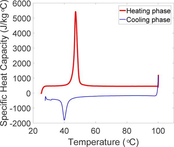
Specific heat capacity of SMA spring for temperatures between 25°C and 100°C
5 Experimental Setups
5.1 Verification of antagonistic SMA model and heat transfer model, and determination of maximum actuation frequency
The experimental setup, shown in Figure 7 was used to determine the experimental behavior of SMAs in antagonistic configuration. In the setup, the tendon connecting the antagonistic SMA springs was wound around the shaft of a rotary encoder. We ensured that the tendon and the encoder shaft were in contact at all times so that the spring deflection could be determined through the angle change measured by the encoder. The two SMAs were loaded to the same initial displacement and force at the beginning of the experiment. SMA X is the SMA spring that is heated initially and SMA Y is the SMA spring that is not heated initially. Step inputs of ± 10 mm were provided as the control reference while displacement and force data were collected by the rotary encoder and the force sensor, respectively. The experimental data were then compared with the theoretical simulation based on the work in section 3.1. Furthermore, the temperature changes over time during the heating and cooling phases of the SMAs in antagonistic configuration were experimentally determined using identical setup. Force and temperature data were collected while SMA spring X was heated from room temperature to 322 K (49 °C). The effectiveness of the cooling mechanism we proposed was also evaluated through similar experimental setup. A maximum constant current of 4 A was provided to heat the SMA using a motor driver through its current controller. The performance of SMAs was evaluated for sinusoidal references of various amplitudes, including 2 mm, 4 mm, 6 mm, 8 mm, 10 mm, and 12 mm.
Figure 7.
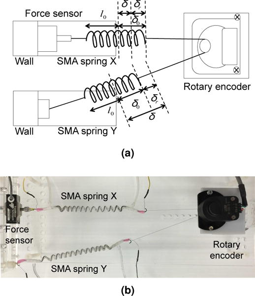
(a) Experimental setup at its initial configuration, where l0, δ0, δ, and δr are the non-stretched length of each SMA spring, initial displacement, final displacement, and stretched/recovered length during each actuation step (b) Actual characterization setup to evaluate the effect of cooling module on the performance of antagonistic SMAs as well as to determine experimental behavior of antagonistic SMAs
5.2 Implementing antagonistic SMA spring actuators on MINIR-II
The SMA spring actuators with integrated cooling modules were configured in an antagonistic configuration and set up as shown in Figure 8 to move a robot segment in one plane. We tested our actuators with the end segment of MINIR-II that consists of parallel springs: a flexible innerspring backbone comprising of three segments and an outer spring for maintaining the robot shape. Each segment of the robot has a length of 19 mm. The robot is 3-D printed and is made of verowhite plastic. Each spring actuator has an unstretched length of approximately 50 mm and was pre-stretched by 25 mm. The two springs were connected to each other directly by a fish wire. The wire was routed around the rotary encoder to ensure the tension of the unactuated spring on the robot segment was always zero. Each of the antagonistic springs was then connected through tendon driven mechanism to the robot end segment by a fish wire to move it back and forth. The first two segments of the robot were constrained during the experiment. We used the rotary encoder to measure the displacement of the SMA springs during the experiment. This allows us to provide step inputs in terms of SMA displacement in both directions and therefore enables the robot to move at a specified frequency. We used a vision system with markers to track the angular displacement of the end segment of MINIR-II.
Figure 8.
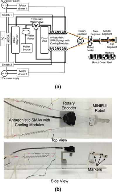
(a) Schematics and actual arrangement of the experimental setup involving antagonistic pair of SMA springs to move only the end segment (b) SMA springs in antagonistic configuration for actuating single robot joint (Tendons in the top view are highlighted in black for clarity)
6 Results and Discussion
The SMA model was verified by comparing the theoretical simulation with the experimental result. Both antagonistic SMA springs have the same parameters, as seen in Table 1. They also started with the same initial displacement and force during the experiment. We provided step inputs of ±10 mm and recorded the change in force and displacement. The experimental setup is shown in Figure 7.
The simulation begins with the same initial displacement, δ0 = 25 mm, and force, F0 = 1.24 N, as the experiment. The initial condition is indicated with ‘*’ in Figure 9. Then, we followed the following four steps to complete the simulation of one motion cycle of the antagonistic SMA springs (Subscript ‘X’ denotes SMA X while subscript ‘Y’ denotes SMA Y):
Figure 9.
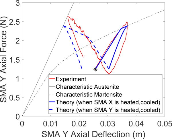
Experimental data and theoretical simulation of the behavior of SMA spring Y, starting from initial position ‘*’. When its antagonistic spring, SMA X, is heated, SMA Y is stretched for +10 mm (solid blue). SMA Y then unloads upon cooling of SMA X. When SMA Y is heated, its displacement trajectory (dotted blue) goes towards negative direction until it intersects with its characteristic austenite graph. It then unloads upon cooling.
Step 1
Since the SMA’s initial displacement is under the martensite graph and is such that , where and are the axial deflections that correspond to and (see Figures 4 and 9), the initially non-heated SMA, SMA Y, would be loaded in such a way that the net force and displacement increase linearly with the stiffness slope of GM. It should be noted that the general force-displacement equation for each SMA spring is stated in Eq. (9). During the simulation, the equation governing SMA X, which is heated initially, is obtained by substituting Eq. (10) into Eq. (9) and is expressed as:
| (29) |
is equal to in Eq. (9) for SMA Y. Therefore, the equation governing SMA Y is expressed as:
| (30) |
Since we pre-strain both SMA springs to the same deflection, hence . The relationship between δX and δY is described by:
| (31) |
Combining Eq. (29), Eq. (30) and Eq. (31), we obtain:
| (32) |
where in Eq. (32). Using Eq. (11a) and Eq. (11b) to simulate the change in martensite volume fraction in SMA X, we can solve numerically Eq. (32). In this case, ξX drops from 1 to 0.27 when the linear increase of the non-heated SMA Y trajectory intersects the characteristic martensite graph.
Step 2
Once the force-displacement trajectory of SMA Y reaches the characteristic martensite graph, it would follow the martensite path while being loaded by the heated SMA. SMA X is governed by the same equation as Eq. (29). SMA Y has the same governing equation as SMA X, except that , since ξY = 1. The equation of SMA Y is expressed as:
| (33) |
The relationship between δX and δY is now:
| (34) |
Combining Eq. (29), Eq. (33) and Eq. (34), we obtain:
| (35) |
While solving Eq. (35), we use Eq. (11a) and Eq. (11b) to simulate the change in martensite volume fraction in SMA X, and Eq. (12a) to simulate the change in detwinned martensite volume fraction in SMA Y. This behavior can be simulated for 0 < ξX < 0.27. Temperature from the beginning of step 1 to the end of step 2 is between the austenite start and austenite finish temperatures, adjusted to match the stress levels.
Step 3
The heated SMA X trajectory at this point should have intersected with the characteristic austenite plot. The cooling process for SMA X then follows, allowing SMA Y to unload. The equations for SMA X and SMA Y are the same as those from Step 1, namely Eq. (29) and Eq. (30). and are both 0 since it is initially in the austenite phase. remains unchanged because a non-heated SMA does not change its phase during its unloading.The relationship between δX and δY are, however, not the same as in Step 1. They are instead the same as Eq. (34) in Step 2. Combining Eq. (29), Eq. (30) and Eq. (34), we obtain:
| (36) |
We use Eq. (13a) to simulate the change in detwinned martensite volume fraction in SMA X in Eq. (36).
Step 4
SMA X currently becomes the non-heated SMA spring while SMA Y gets heated. We will repeat step 1 since SMA X has a displacement under the characteristic martensite graph as well. Therefore, steps 1 to 3 are repeated to complete one motion cycle.
Figure 9 shows the theoretical and experimental results of SMA Y that was actuated over one motion cycle of 10 ± mm. Both results showed similar trend and covered the same value range. The interaction between the silicone tube and the SMA spring during its motion, and the loading history of the SMA could have contributed to the discrepancy between the theoretical and experimental data.
We verified the heat transfer model by comparing the simulation of temperature change of SMA over time with the experimental data. The experimental setup is shown in Figure 7 and a current of 1 A was supplied to heat the SMA spring so that it reached the desired temperature at 322 K. Once the desired temperature was reached, the current was turned off and water was allowed to flow through the cooling channel to cool the SMA. The temperature change in the SMA spring was recorded during its heating and cooling phases. Experimental data that include strain change, Reynolds Number of the water flow and current applied were used in the heat transfer model to simulate the temperature profile. The results are shown in Figure 10, that shows that the model matches the experiment well in both heating and cooling phases with an R2-value of 0.946.
Figure 10.
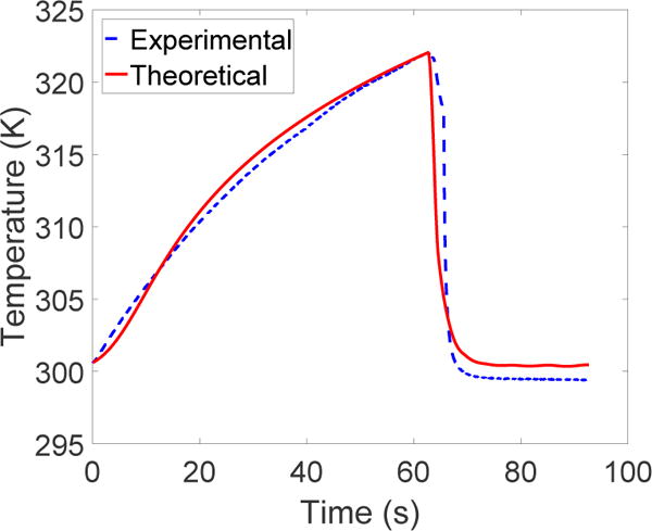
Comparison of theoretical and experimental data for temperature vs time during the heating and cooling periods
The maximum frequency of the antagonistic SMA spring actuators is determined by the coefficient of determination (R2-value) > 0.9 between the the sinusoidal reference and the actual data. As shown in Figure 11, the cooling module provided significant improvement over natural cooling by air in terms of the SMA’s ability to actuate at higher frequency. Forced convection by water in the tube allowed the SMA spring to follow a sinusoidal input with frequency of 0.143 Hz (7 s period) for an amplitude of 2 mm (R2-value = 0.9927). Under natural cooling by air, the trajectory was well tracked for the initial 5 periods (R2-value = 0.9585). After that, the residual heat remaining in either SMA spring built up and eventually resisted the motion in either direction, causing the discrepancy between the reference and the actual data. We did not observe such degradation in performance when the SMA was actuated under forced water cooling. We also performed the same experiment using the cooling module-integrated SMA springs for several motion amplitudes, ranging from 2 mm to 12 mm. The result is shown in Figure 12, where we observe that an increase in motion amplitude corresponds to a decrease in maximum actuation frequency. Besides that, at high amplitudes, the effect of low heating efficiency due to the static water retained in the cooling module can be observed. Hence, in our future work, we need to remove water from the cooling module during the heating phases to obtain a more satisfactory system performance and improve its efficiency.
Figure 11.
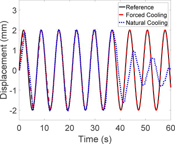
Tracking of sinusoidal trajectory of 2 mm amplitude and 7 s period under natural cooling by surrounding air (without cooling module) and forced convection by flowing water (with cooling module)
Figure 12.
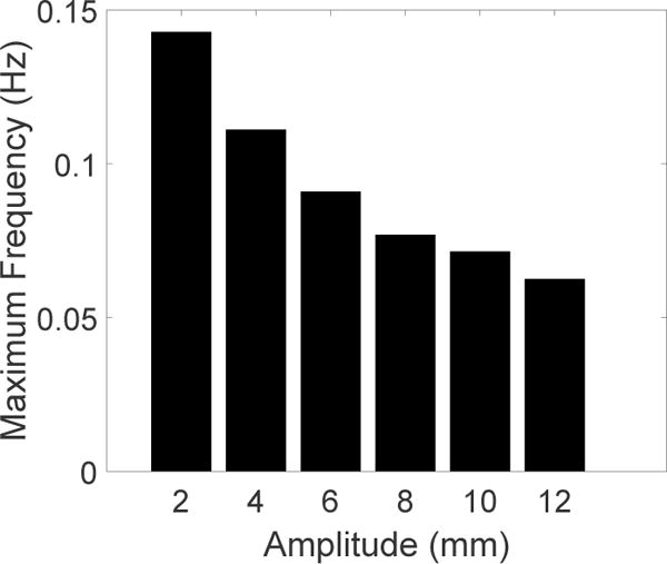
Maximum frequencies that can be achieved by antagonistic SMA springs with integrated cooling modules in response to sinusoidal inputs of different amplitudes
We implemented our cooling module-integrated SMA springs on MINIR-II robot to move its end segment back and forth along the vertical axis. By contracting the SMA by ±4 mm, shown in Figure 13(a), we were able to move the end segment of the robot by approximately ±25°, as shown in Figure 13(b). The back and forth motion of the end segment of the robot is shown in Figure 14. In our future work, we envision using an imaging modality to achieve a more precise control of the configuration of the robot in the workspace.
Figure 13.
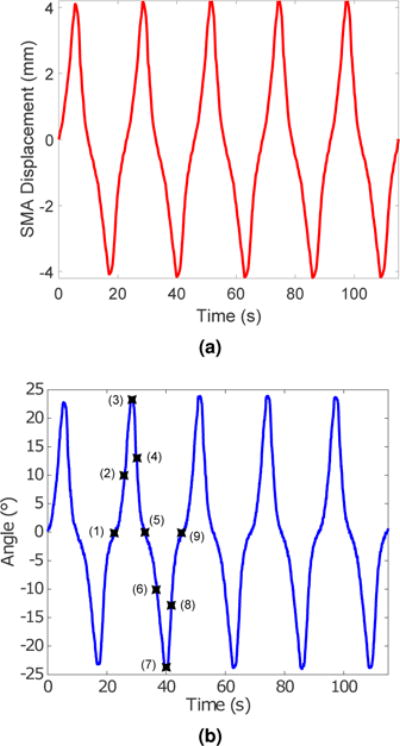
(a) SMA displacement and (b) the corresponding angular displacement of the end robot segment (Actual positions of the end robot segment at stages labeled (1) through (9) are shown in Fig. 14.)
Figure 14.
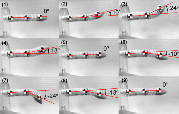
The end segment of MINIR-II robot moves back and forth under active cooling of SMA actuators (Base and middle segments were constrained). The red lines are superimposed in the figure for clarity.
7 Conclusion
In this paper, we proposed a cooling module that is integrated with an SMA spring to form a compact actuator. We presented our work on the SMA spring model in an antagonistic setup, simulated it based on various initial conditions for one motion cycle, and verified the simulation with the experimental results. We also presented the heat transfer model that simulates the temperature change of SMA over time. The model was compared with the experimental data for one heating and cooling cycle of the SMA spring. The proposed cooling module integrated SMA spring actuator significantly improves the actuation frequency and it is important we were able to achieve it over a sustained period of time. We also implemented the actuators on a single segment of MINIR-II and commanded the SMAs to move over ±4 mm, which corresponds to an angular displacement of approximately ± 25° in the robot. In our future work, we will remove the static water from the water module during the heating phases, create a better seal to prevent water leakage and investigate more tube dimensions to achieve a smoother water flow. These improvements are critical to improving the maximum actuation frequency of the SMA especially for large ranges of motion. The models developed in this paper will be utilized in a control framework to improve control of SMA actuation. The work presented is the first step towards our eventual goal of developing a near real-time SMA actuated actively cooled multi-degree-of-freedom MINIR-II for MRI-guided neurosurgery.
Acknowledgments
Research reported in this publication was supported by the National Institute of Biomedical Imaging And Bioengineering of the National Institutes of Health under Award Number R01EB015870. The content is solely the responsibility of the authors and does not necessarily represent the official views of the National Institutes of Health. We would like to acknowledge Mr. Bhanu Sood from Center for Advanced Life Cycle Engineering (CALCE) at University of Maryland, College Park for the DSC system.
References
- Aguiar RAA, Neto WCDCL, Savi MA, Pacheco PMCL. Shape memory alloy helical springs performance: Modeling and experimental analysis. Materials Science Forum. 2013;758(2013):147–156. [Google Scholar]
- Aguiar RAA, Savi MA, Pacheco PMCL. Experimental and numerical investigations of shape memory alloy helical springs. Smart Materials and Structures. 2010;19(2):025008. [Google Scholar]
- American Brain Tumor Association. Brain tumor statistics. 2015 Available at: www.abta.org/about-us/news/brain-tumor-statistics/ (accessed 30 March 2015)
- An SM, Ryu J, Cho M, Cho KJ. Engineering design framework for a shape memory alloy coil spring actuator using a static two-state model. Smart Materials and Structures. 2012;21(5):055009. [Google Scholar]
- Bhattacharyya A, Sweeney L, Faulkner MG. Experimental characterization of free convection during thermal phase transformations in shape memory alloy wires. Smart Materials and Structures. 2002;11(3):411. [Google Scholar]
- Boyd J, Lagoudas D. A thermodynamical constitutive model for shape memory materials. part I. the monolithic shape memory alloy. International Journal of Plasticity. 1996;12(6):805–842. [Google Scholar]
- Brinson L. One-dimensional constitutive behavior of shape memory alloys: Thermomechanical derivation with non-constant material functions and redefined martensite internal variable. Journal of Intelligent Material Systems and Structures. 1993;4(2):229–242. [Google Scholar]
- Bucchi F, Elahinia M, Forte P, Frendo F. A passive magneto-thermo-mechanical coupling actuated by sma springs and mr fluid. International Journal of Structural Stability and Dynamics. 2014;14(08):1440031. [Google Scholar]
- Cheng SS, Desai JP. Robotics and Automation (ICRA), 2015 IEEE International Conference on. IEEE; 2015. Towards high frequency actuation of SMA spring for the neurosurgical robot-MINIR-II; pp. 2580–2585. [Google Scholar]
- Cheng SS, Kim Y, Desai JP. Towards real-time SMA control for a neurosurgical robot: MINIR-II. Proceedings of the International Symposium on Robotics Research (ISRR 2015) 2015 In Press. [Google Scholar]
- Churchill SW, Chu HH. Correlating equations for laminar and turbulent free convection from a horizontal cylinder. International Journal of Heat and Mass Transfer. 1975;18(9):1049–1053. [Google Scholar]
- Comparetti M, De Momi E, Vaccarella A, Riechmann M, Ferrigno G. Optically tracked multi-robot system for keyhole neurosurgery. Robotics and Automation (ICRA), 2011 IEEE International Conference on. 2011:661–666. [Google Scholar]
- De Lorenzo D, De Momi E, Dyagilev I, Manganelli R, Formaglio A, Prattichizzo D, Shoham M, Ferrigno G. Force feedback in a piezoelectric linear actuator for neurosurgery. The International Journal of Medical Robotics and Computer Assisted Surgery. 2011;7(3):268–275. doi: 10.1002/rcs.391. [DOI] [PubMed] [Google Scholar]
- de Sousa VC, Junior CDM. Effect of pseudoelastic hysteresis of shape memory alloy springs on the aeroelastic behavior of a typical airfoil section. Journal of Intelligent Material Systems and Structures. 2014 1045389X14563862. [Google Scholar]
- de Sousa VC, Junior CDM, Elahinia MH. Effect of constitutive model parameters on the aeroelastic behavior of an airfoil with shape memory alloy springs. Journal of Vibration and Control. 2016 1077546316657501. [Google Scholar]
- Dynalloy. Technical Characteristics of FLEXINOL Actuator Wires. Technical report 2011 [Google Scholar]
- Elahinia MH, Hashemi M, Tabesh M, Bhaduri SB. Manufacturing and processing of niti implants: a review. Progress in Materials Science. 2012;57(5):911–946. [Google Scholar]
- Ertel JD, Mascaro SA. Dynamic thermomechanical modeling of a wet shape memory alloy actuator. Journal of Dynamic Systems, Measurement, and Control. 2010;132:45–57. [Google Scholar]
- Fand R, Keswani K. The influence of property variation on forced convection heat transfer to liquids. International Journal of Heat and Mass Transfer. 1972;15(8):1515–1536. [Google Scholar]
- Frémond M. Shape Memory Alloys, International Centre for Mechanical Sciences. Vol. 351. Springer; Vienna: 1996. Shape memory alloy; pp. 1–68. [Google Scholar]
- Hadi A, Yousefi-Koma A, Moghaddam MM, Elahinia M, Ghazavi A. Developing a novel SMA-actuated robotic module. Sensors and Actuators A: Physical. 2010;162(1):72–81. [Google Scholar]
- Ho M, Desai JP. Robotics and Automation (ICRA), 2012 IEEE International Conference on. IEEE; 2012. Towards the development of a SMA-actuated MRI-compatible tendon-driven neurosurgical robot; pp. 683–688. [Google Scholar]
- Ho M, Desai JP. Modeling, characterization and control of antagonistic SMA springs for use in a neurosurgical robot. Robotics and Automation (ICRA), 2013 IEEE International Conference on. 2013:2503–2508. [Google Scholar]
- Ho M, Kim Y, Cheng SS, Gullapalli R, Desai JP. Design, development, and evaluation of an MRI-guided SMA spring-actuated neurosurgical robot. The International Journal of Robotics Research. 2015 doi: 10.1177/0278364915579069. 0278364915579069. [DOI] [PMC free article] [PubMed] [Google Scholar]
- Ho M, Koltz M, Simard JM, Gullapalli R, Desai JP. Robotics and Automation (ICRA), 2011 IEEE International Conference on. IEEE; 2011. Towards a MR image-guided SMA-actuated neurosurgical robot; pp. 1153–1158. [Google Scholar]
- Ho M, McMillan AB, Simard JM, Gullapalli R, Desai JP. Toward a meso-scale SMA-actuated MRI-compatible neurosurgical robot. Robotics, IEEE Transactions on. 2012;28(1):213–222. doi: 10.1109/TRO.2011.2165371. [DOI] [PMC free article] [PubMed] [Google Scholar]
- Incropera FP. Fundamentals of Heat and Mass Transfer. John Wiley & Sons; 2006. [Google Scholar]
- Jackson CM, Wagner HJ, Wasilewski RJ. Technical report, NASA-SP 5110. 1972. 55-Nitinol-the alloy with a memory: Its physical metallurgy, properties and applications. [Google Scholar]
- Kim D, Kobayashi E, Dohi T, Sakuma I. A new, compact MR-compatible surgical manipulator for minimally invasive liver surgery. 2002;2488:99–106. [Google Scholar]
- Kim Y, Cheng SS, Desai JP. SPIE Medical Imaging. International Society for Optics and Photonics; 2015. Towards the development of a spring-based continuum robot for neurosurgery; pp. 94151Q–94151Q. [Google Scholar]
- Kim Y, Cheng SS, Ecins A, Fermüller C, Westlake KP, Desai JP. Proceedings of ASME 2014 Dynamic Systems and Control Conference. ASME; 2014. Towards a robotic hand rehabilitation exoskeleton for stroke therapy. [Google Scholar]
- Kim Y, Desai JP. Intelligent Robots and Systems (IROS), 2015 IEEE/RSJ International Conference on. IEEE; 2015. Design and kinematic analysis of a neurosurgical spring-based continuum robot using sma spring actuators; pp. 1428–1433. [Google Scholar]
- Krulevitch P, Lee A, Ramsey P, Trevino J, Hamilton J, Northrup M. Thin film shape memory alloy microactuators. Microelectromechanical Systems, Journal of. 1996;5(4):270–282. [Google Scholar]
- Lagoudas DC, Moorthy D, Qidwai MA, Reddy JN. Modeling of the thermomechanical response of active laminates with SMA strips using the layerwise finite element method. Intelligent Material Systems and Structures. 1997;8(88):476. [Google Scholar]
- Lewis N, York A, Seelecke S. Experimental characterization of self-sensing SMA actuators under controlled convective cooling. Smart Materials and Structures. 2013;22(9):094012. [Google Scholar]
- Liang C, Rogers CA. One-dimensional thermomechanical constitutive relations for shape memory materials. Journal of Intelligent Material Systems and Structures. 1990;1(2):207–234. [Google Scholar]
- Liang C, Rogers CA. Design of shape memory alloy springs with applications in vibration control. Journal of Intelligent Material Systems and Structures. 1997;4(2):229–242. [Google Scholar]
- Loh CS, Yokoi H, Arai T. Natural heat-sinking control method for high-speed actuation of the SMA. International Journal of Advanced Robotic Systems. 2006;3(4) [Google Scholar]
- Louw DF, Fielding T, McBeth PB, Gregoris D, Newhook P, Sutherland GR. Surgical robotics: A review and neurosurgical prototype development. Neurosurgery. 2004;54(3) doi: 10.1227/01.neu.0000108638.05274.e9. [DOI] [PubMed] [Google Scholar]
- Luo Y, Takagi T, Maruyama S, Yamada M. A shape memory alloy actuator using peltier modules and R-phase transition. Journal of Intelligent Material Systems and Structures. 2000;11(7):503–511. [Google Scholar]
- Ma J, Huang H, Huang J. Characteristics analysis and testing of SMA spring actuator. Advances in Materials Science and Engineering 2013 2013 [Google Scholar]
- Ma N, Song G, Lee H. Position control of shape memory alloy actuators with internal electrical resistance feedback using neural networks. Smart materials and structures. 2004;13(4):777. [Google Scholar]
- Manach PY, Favier D. Shear and tensile thermomechanical behavior of near equiatomic NiTi alloy. Materials Science and Engineering: A. 1997;222(1):45–57. [Google Scholar]
- McNaney JM, Imbeni V, Jung Y, Papadopoulos P, Ritchie R. An experimental study of the superelastic effect in a shape-memory nitinol alloy under biaxial loading. Mechanics of Materials. 2003;35(10):969–986. [Google Scholar]
- Ng K, Sun Q. Stress-induced phase transformation and detwinning in NiTi polycrystalline shape memory alloy tubes. Mechanics of Materials. 2006;38(12):41–56. Macro-, Meso-, Micro- and Nano-Mechanics of Materials. [Google Scholar]
- Pathak A, Brei D, Luntz J. Student’s papers. Ascona, Switzerland: 2008. Experimental characterization of the convective heat transfer from shape memory alloy SMA wire to various ambient environments; p. 12. [Google Scholar]
- Russell RA, Gorbet R. Improving the response of SMA actuators. Robotics and Automation, 1995 IEEE International Conference on. 1995;3:2299–2304. [Google Scholar]
- Selden B, Cho KJ, Asada H. Segmented binary control of shape memory alloy actuator systems using the peltier effect. Robotics and Automation, 2004. Proceedings. ICRA ’04. 2004 IEEE International Conference on. 2004;5:4931–4936. [Google Scholar]
- Shigley JE. Mechanical engineering design. McGraw-Hill; 1972. [Google Scholar]
- Spectrum Health. iMRI technology leads to better neurosurgical results for patients. 2015 Available at: www.spectrumhealth.org/iMRI (accessed 15 December 2015)
- Tamai H, Kitagawa Y. Pseudoelastic behavior of shape memory alloy wire and its application to seismic resistance member for building. Computational Materials Science. 2002;25(12):218–227. [Google Scholar]
- Tanaka K. A thermomechanical sketch of shape memory effect: One-dimensional tensile behavior. Res Mechanica. 1986;18(3):251–263. [Google Scholar]
- Thamburaja P, Anand L. Superelastic behavior in tension–torsion of an initially-textured Ti-Ni shape-memory alloy. International Journal of Plasticity. 2002;18(11):1607–1617. [Google Scholar]
- Thompson DM, Griffin OH. Finite element predictions of active buckling control of stiffened panels. Intelligent Material Systems and Structures. 1993;4(7):243. [Google Scholar]
- Tobushi H, Tanaka K. Deformation of a shape memory alloy helical spring (analysis based on stress-strain-temperature relation) JSME International Journal. 1991;34(1) [Google Scholar]
- Wang Y, Cole G, Su H, Pilitsis J, Fischer G. MRI compatibility evaluation of a piezoelectric actuator system for a neural interventional robot. Engineering in Medicine and Biology Society, 2009. EMBC 2009. Annual International Conference of the IEEE. 2009:6072–6075. doi: 10.1109/IEMBS.2009.5334206. [DOI] [PubMed] [Google Scholar]
- Yang B, Roys S, Tan UX, Philip M, Richard H, Gullapalli RP, Desai JP. Design, development, and evaluation of a master-slave surgical system for breast biopsy under continuous MRI. The International Journal of Robotics Research. 2013 doi: 10.1177/0278364913500365. 0278364913500365. [DOI] [PMC free article] [PubMed] [Google Scholar]
- Yates SJ, Kalamkarov AL. Experimental study of helical shape memory alloy actuators: effects of design and operating parameters on thermal transients and stroke. Metals. 2013;3(1):123–149. [Google Scholar]
- Zhang Lx, Hu Gx, Wang Zg. Study on liquid-jet cooling and heating of the moving SMA actuator. International Journal of Thermal Sciences. 2008;47(3):306–314. [Google Scholar]
- Zimmermann M, Krishnan R, Raabe A, Seifert V. Robot-assisted navigated endoscopic ventriculostomy: implementation of a new technology and first clinical results. Acta Neurochirurgica. 2004;146(7):697–704. doi: 10.1007/s00701-004-0267-7. [DOI] [PubMed] [Google Scholar]


