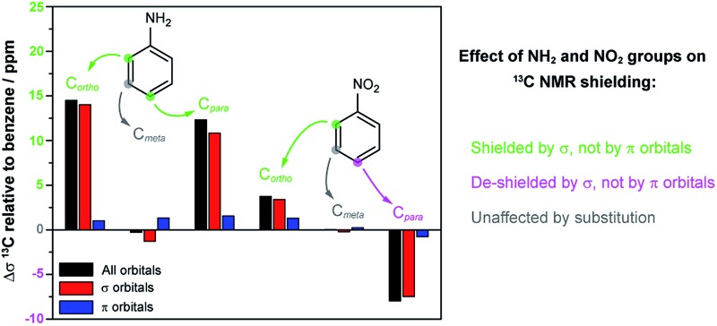
 NH2 and NO2 group effects on 13C NMR chemical shifts in substituted benzenes are explained by σ- instead of π-orbitals.
Abstract
Effects of electron-donating (R = NH2) and electron-withdrawing (R = NO2) groups on 13C NMR chemical shifts in R-substituted benzene are investigated by molecular orbital analyses. The 13C shift substituent effect in ortho, meta, and para position is determined by the σ bonding orbitals in the aryl ring. The π orbitals do not explain the substituent effects in the NMR spectrum as conventionally suggested in textbooks. The familiar electron donating and withdrawing effects on the π system by NH2 and NO2 substituents induce changes in the σ orbital framework, and the 13C chemical shifts follow the trends induced in the σ orbitals. There is an implicit dependence of the σ orbital NMR shift contributions on the π framework, via unoccupied π* orbitals, due to the fact that the nuclear shielding is a response property.
13C NMR chemical shifts can be used to detect substituent effects on aromatic compounds, which, in turn, are associated with the chemical reactivity of the benzene ring in electrophilic aromatic substitutions.1–3 Benzene ring substituents are classified as activating or deactivating towards electrophilic attack; the former increase the π electron density at the ring whereas the latter decrease it. Moreover, the (de-)activation causes the substituents to be ortho-, meta-, or para-directing.3 For instance, the NH2 substituent is activating and ortho- and para-directing, whereas NO2 is deactivating and meta-directing.3 The substituent effects are usually divided into inductive (or field-) effects, and resonance (or mesomeric) effects, which are thought to be transmitted via the σ and π bonding frameworks, respectively.4–6 The inductive effect is electron-withdrawing from the aryl ring for both NO2 and NH2 but more pronounced for NO2 because of the combined electronegativity of the nitrogen and oxygen atoms.7–9
The contrasting behavior of the two groups toward directing electrophilic substitutions is commonly explained by π-resonance structures, suggesting an accumulation of π electron density at the ortho and para ring positions in the presence of an NH2 group, and depletion of π density at the same positions by an NO2 group.8,10 Recent computational results by Stasyuk et al. 8 utilizing Kohn–Sham (KS) density functional theory and a Voronoi Deformation Density (VDD) charge analysis reinforce these classical arguments and the importance of the π electron delocalization in aniline and nitrobenzene.
The electron-donating and -withdrawing substituent effects in aromatic compounds are associated with pronounced changes in 13C NMR chemical shifts.11–16 In a simple model, one associates higher electron density with increased magnetic shielding, i.e. less positive chemical shifts. Donating electron groups are then expected to shield the carbon nuclei located at ortho and para positions, whereas withdrawing electron substituents de-shield at the same positions. meta positions are usually unaffected by the substituents, in agreement with the model.1–3 This type of reasoning is often applied to rationalize the effect of substituents on the nuclear shielding at meta- and para-positions. ortho-Positions show a more complex behavior than the meta and para analogs due to the proximity of the substituent.17–19 For example, the nitro group causes an increased shielding of ortho-carbons instead of the expected de-shielding similar to that taking place at the para position.1,11
π orbitals are commonly invoked to explain the effects of electron donating and withdrawing groups on the 13C chemical shifts. However, the large shifts of the protons in benzene itself, classically explained by a π ring-current anisotropy model, were shown to be caused by a large magnetic de-shielding from σ orbitals.20,21 It is not clear from the literature what role the σ orbitals may play in the 13C chemical shift substituent trends, if any, or what the shielding vs. de-shielding mechanisms are for each type of orbital symmetry in relation to the substituent positions. The present study aims at filling this gap of knowledge, by analyzing results from first-principles calculations for benzene, aniline, and nitrobenzene. Quantum mechanical analyses in terms of ‘chemist's orbitals’ representing individual bonds, core shells, lone pairs, and antibonding orbitals, gain insight into how stereoelectronic interactions influence the NMR chemical shifts. The results of the analysis appear to be unintuitive, at first, because the σ orbitals are responsible for the known substituent effects in the 13C chemical shifts. However, we also show that there is nonetheless a clear relation between the NMR shift effects and the known chemical effects of the substituents.
Methods
The Amsterdam Density Functional suite (ADF, version 2014)22–24 was used for all calculations. KS geometry optimizations and 13C NMR shielding tensor calculations were carried out with the PBE0 hybrid functional,25 the triple-ζ Slater-type atomic orbital (STO) basis with two sets of polarized functions (TZ2P) from the ADF basis set library, recommended options for hybrid functionals, and ‘very good’ Becke integration grids.26 The conductor-like screening model (COSMO)27 with parameters for chloroform was applied to simulate (weak) solvent effects.
13C chemical shifts are referenced to TMS. The 13C shifts δ i were calculated via
| δi = σbenz – σi + δbenz | 1 |
where σ i is the calculated shielding of the carbon nucleus of interest, and σ benz and δ benz are the calculated carbon shielding and the experimental chemical shift with respect to TMS, respectively, of benzene. It is important to note that the trends analyzed herein are not affected by the nature of the intermediate reference.
An NMR shielding analysis was carried out along the lines of ref. 28–30 in terms of natural localized molecular orbitals (NLMOs) generated by the NBO 6.0 program.31 A synopsis is given below in the context of the present work.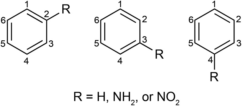
In order to simplify the discussion, the NMR shift is always the one calculated for carbon no. 1 (C1) in the scheme above, with the R-group in ortho, meta, or para position relative to C1. The calculated C1 NMR shielding tensor (σ total) was decomposed into contributions of the diamagnetic (σ dia) and paramagnetic (σ para) mechanisms. The role of the σ and π orbitals was rationalized via analyses of σ total, and its dia and para contributions, in terms of individual orbitals. The effect of the magnetic field orientation relative to the molecule was analyzed by considering the principal components σ11, σ22 and σ33 of the shielding tensor in its molecule-fixed principal axis system (PAS). For R-benzene, the σ11 and σ22 components of the C1 shielding tensor lie in the aryl ring plane, while the most positive tensor component, σ33, is perpendicular to the aryl ring plane. The contributions and the complete set of shielding analysis data is provided in the ESI, Tables S3 and S4.†
Atomic charges were calculated by the Voronoi Deformation Density (VDD)8,32,33 partitioning. Molecular structures were optimized with C s symmetry to allow a decomposition of the total charges into a′ and a′′ irreducible representations, corresponding to the σ and π frameworks, respectively. To analyze the charge rearrangements on the benzene ring caused by the R substituents, Ph˙ and R˙ radical fragments were generated using a restricted open-shell KS approach.
Results and discussion
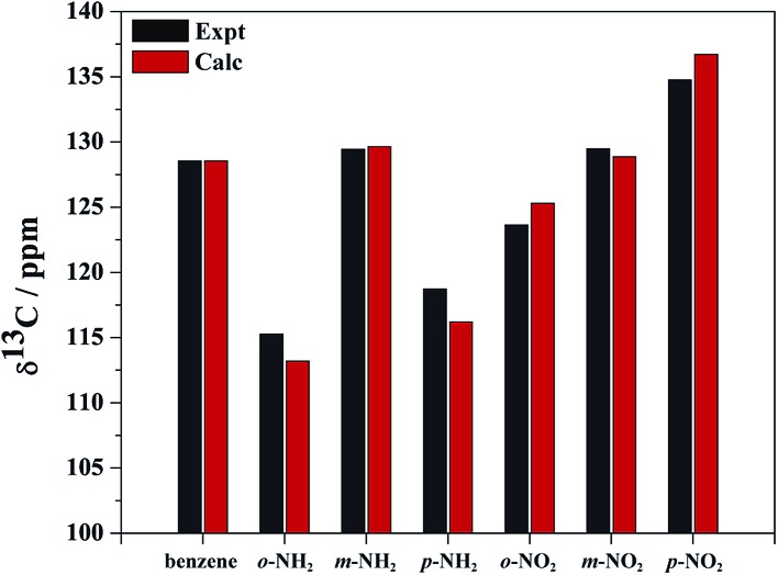
The calculated and experimental 13C NMR chemical shifts (Table S1†) show good agreement with the experimental data (Fig. 1). The calculated and experimental shifts deviate from each other by no more than 2%, which is acceptable. Importantly, the experimentally observed trends are faithfully reproduced by the calculations, which means that a meaningful analysis of the trends can be carried out at the chosen level of theory.
Fig. 1. Calculated (Calc) and experimental (Expt) carbon 1 (C1) isotropic 13C NMR chemical shifts for benzene, NH2–benzene, and NO2–benzene. ortho (o-), meta (m-), and para (p-) correspond to the C1 position relative to R.
Relative to benzene, the carbon nuclei have smaller shifts upon NH2 substitution in ortho and para positions. The NH2 group effect is larger for ortho than para. Relative to benzene, the NO2 substituent causes opposite effects for the ortho and para positions: the carbon shift becomes larger with NO2 in the para position, while the shift decreases in the ortho position. The carbon shifts in meta position are hardly affected by the substituents.
In the following, we focus on the nuclear magnetic shielding rather than the chemical shift, as it is the more fundamental physical quantity. The shift and shielding scales have opposite signs (eqn (1)). To re-state the trends in terms of shielding:
(1) Relative to benzene, the NH2 substituent causes increased shielding both in ortho and para positions.
(2) Relative to benzene, the NO2 substituent causes increased shielding of in ortho and de-shielding in para position.
It is important to keep in mind that the terms paramagnetic and diamagnetic are used to refer to different (although somewhat arbitrarily defined) mechanisms that contribute to the total shielding, not the sign of observed trends in the shielding constants or chemical shifts among the set of compounds. However, the diamagnetic shielding is indeed positive for carbon and tends to vary comparatively little among different compounds, while the paramagnetic contribution is usually negative and determines the magnitude and direction of the chemical shift.
The observed shielding trends are indeed associated with the paramagnetic shielding mechanism (Table S2†). In KS theory, the paramagnetic shielding can be expressed in terms of canonical molecular orbitals (CMOs, the ‘usual’ orbitals from self-consistent field KS calculations) for each tensor element σ u,v, with u,v ∈ {x, y, z}, as30
 |
2 |
here, φ i, ε i and φ a, ε a represent occupied and unoccupied KS CMOs and their energies, respectively. The superscript OZ refers to the orbital Zeeman perturbation due to the external magnetic field. The superscript PSO refers to the paramagnetic nuclear spin – electron orbital perturbation due to the nuclear spin hyperfine magnetic field. Further, F and ĥ are the KS Fock operator and its one-electron part. The OZ and PSO perturbations of F and ĥ may be swapped. Irrespective of whether the shielding analysis is carried out in terms of canonical or localized orbitals, eqn (2) indicates that the paramagnetic shielding is associated with magnetic coupling between occupied and unoccupied orbitals, represented by the OZ and PSO matrix elements in the numerators, and the energy gaps between occupied and unoccupied orbitals in the denominators. In the NLMO analysis, the summation over unoccupied orbitals is absorbed into the contributions from each occupied NLMO after transforming the occupied CMO set to the NLMOs.
Both the OZ and PSO matrix elements involve orbital angular momentum operators, because the associated magnetic moments are proportional to the angular momentum (for closed-shell molecules with light elements, the electron spin magnetic moments do not contribute to the shielding). However, in the PSO operators the angular momentum is weighted by the inverse-cube of the electron-nucleus distance. Therefore, the PSO operators mainly sample the electronic structure around the nucleus of interest. The action of a component of the angular momentum operator on an atomic orbital (AO) can be represented by a rotation of the AO (e.g. 90° for a 2p AO) or it gives zero (e.g. Lzpz). In order for a matrix element unocc|ĥPSOv|occ to be large, one therefore has to consider the action of an angular momentum component v on the part of the occupied orbital that is centered around the NMR nucleus, and whether the resulting ‘rotated’ orbital has a large overlap with an unoccupied orbital around the same nucleus. The associated paramagnetic shielding contribution, usually negative, is particularly large if the two orbitals are close in energy. This type of analysis for the paramagnetic shielding is sometimes referred to as an ‘orbital rotation model’.34 Note that such models usually rely on a σ/π partitioning of the molecular orbitals, and consequently we used LMOs that have the same partitioning. We do not expect our results to change qualitatively if a different localization technique is used, as long as the localization also gives σ and π orbitals and not the ‘banana bond’ orbitals for multiple bonds that are produced by some orbital localization methods. (Using one of the latter would also not allow us to make connections with the textbook explanations for the shielding trends, and therefore not be suitable for the present study.)
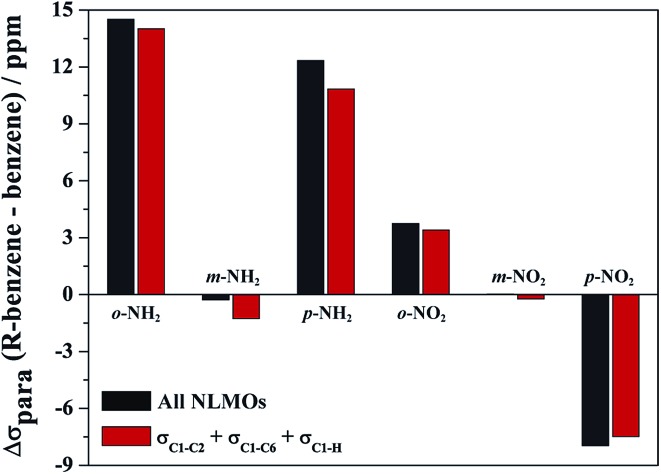
Only very few orbitals dictate the R effects in the isotropic shielding in R–benzene, as shown in Fig. 2 by comparing the full substituent effects (i.e. from all NLMOs) with the added contributions from just the three σ-bonding NLMOs σC1–C2, σC1–C6, and σC1–H. This simplifies the analysis considerably. Fig. 2 also implies that the σ framework of orbitals is predominantly responsible for the substituent effects on the NMR carbon shifts, not the π system. We consider this one of the main findings of the present study.
Fig. 2. Sum of all orbital contributions (all occupied NLMOs) and of only the σC1–C2, σC1–C6, and σC1–H contributions to the isotropic part of σ para term of the C1 shielding for R–benzenes (ppm). ortho (o-), meta (m-), and para (p-) is the C1 position relative to R. Shielding relative to benzene at 0 ppm.
Further analysis reveals that the substituent effects are associated predominantly with the in-plane principal shielding components (σ11 and σ22). The σ11, σ22, and σ33 components are listed in Table 1. The σ11 trends are associated with the σC1–C NLMOs, while the variations in σ22 are associated with the σC1–H NLMO. (Sometimes, a shielding analysis in terms of CMOs can also be very insightful,35 in particular when shielding effects can be tied to the orbital energy gaps Δε
i,a = ε
i – ε
a in the denominator of eqn (2). We also performed the shielding analysis in terms of CMOs, but decided to forgo a discussion because the trends were less clear, mainly due to the fact that multiple occupied and unoccupied CMOs contribute to the shielding trends and no obvious relationship to the Δε
i,a could be identified.) The reason why these different orbitals contribute to the trends in σ
para
via different principal components, i.e. due to different orientations of the magnetic fields in the aryl plane, is illustrated by Fig. 3. σC1–C and σC1–H rotations around the respective principal axis, associated with the action of the magnetic field, produce rotated NLMOs that overlap effectively with the same low-energy 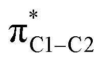 unoccupied orbital. These overlaps go along with strong magnetic couplings resulting in important contributions to σ
para from the different magnetic field directions and orbitals.
Table 1. Sum of σC1–C2, σC1–C6, and σC1–H NLMO contributions to the σ11, σ22, and σ33 principal components of the C1 paramagnetic shielding of R–benzenes (ppm). ortho (o-), meta (m-), and para (p-) is the C1 position relative to R.
| Component | Orbitals a | R |
||||||
| H | o-NH2 | m-NH2 | p-NH2 | o-NO2 | m-NO2 | p-NO2 | ||
| σ11 | σC1–C2/6 | –263.14 | –232.79 | –266.12 | –245.88 | –250.64 | –261.42 | –273.03 |
| σ22 | σC1–H | –208.88 | –188.11 | –210.25 | –195.31 | –216.16 | –212.21 | –222.95 |
| σ33 | –40.69 | –49.75 | –40.13 | –38.97 | –35.66 | –39.79 | –39.16 | |
aOrbitals responsible for the variations in the shielding tensor components depending on the substituent and position relative to C1.
Fig. 3. Isosurfaces (±0.03 au) of σC1–C2 (a) and σC1–H (b) NLMOs that may rotate around C1 under the action of the angular momentum/magnetic moment operator (L) and overlap with the 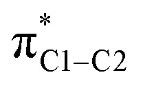 unoccupied orbital. This overlap indicates paramagnetic coupling of σ and π* orbitals.
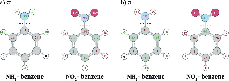
To analyze the effect of the R substituents on the σ and π system of the benzene ring, we follow the strategy of Stasyuk et al. 8 and investigate the electron density rearrangement caused by the R-substitution with the VDD charge analysis method. Fig. 4 displays the σ and π contributions of VDD atomic charges for NH2– and NO2–benzene calculated relative to phenyl and substituent fragments. The VDD charge of an atom is the electron deformation density Δρ = ρ(R–benzene) – ρ(fragments), times –e, integrated over the atomic volume defined by a Voronoi partitioning of the molecule.
Fig. 4. VDD atomic deformation charges (in 10–3 e) for NH2– and NO2–benzene calculated relative to fragments. Negative values mean an accumulation of electron density (negative charge), positive values denote electron density depletion (positive charge). Atomic deformation charges are partitioned into σ (panel a) and π (panel b) contributions upon the C–N bond formation.
NH2 and NO2 substituents are known to be electron-donating and electron-withdrawing, respectively, with respect to the aryl π system, which is reflected in the charge analysis. Fig. 4 shows that the NH2 substituent increases the π density on carbon atoms in the ortho and para positions, whereas the NO2 group causes a depletion of π density at the same positions. We obtain similar values as Stasyuk et al. 8 using the VDD technique and therefore our conclusions are in line with the reference.
Regarding the σ system, the charge analysis shows the opposite behavior to the π system (also observed by Stasyuk et al.).8 While the NH2 group causes a depletion of density at carbon atoms in ortho and para position, an accumulation takes place at the same positions for NO2 substitution. Carbon atoms in the meta positions are basically unaffected by the substitutions. The charge rearrangements in the σ system are only partially explained by the inductive effects of R. The fact that the σ charges are large for the ortho and para positions but negligible for meta, instead of simply decreasing in magnitude with the distance from the substituent, means that there is an energetic stabilization going along with a partial neutralization of the charge rearrangements in the π system by the σ system.
The depletion of σ electron density caused by the NH2 group in ortho and para positions leads to a magnitude reduction of the magnetic coupling between σC1–C,H and 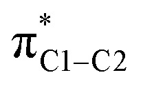 in the paramagnetic shielding. This is clear from Fig. 3. The weight of these occupied orbitals around C1 decreases upon substitution (in Fig. 4, C1 is one of the carbons not bound to the substituent). The reduced weight decreases the overlap of the magnetic-field ‘rotated’ σ orbitals with the π* orbital, and therefore it reduces the magnetic coupling in the paramagnetic shielding. Accordingly, in Table 1, both the σC1–C and σC1–H NLMO contributions to the σ
para term are less negative when the NH2 group is in ortho and para position rather than meta. Therefore, the known effect of the NH2 group, i.e. increased ortho and para shielding, is actually a reduction of de-shielding contributions from the σ system. The larger reduction of electron density in ortho position correlates with the stronger substituent shielding effect in ortho position. For the meta position, the negligible charge effects agree with the similar carbon shielding in benzene vs. the substituted systems.
Despite this increased ortho and para shielding being tied to the occupied σ orbitals, we can connect the less effective paramagnetic mechanism of the σC1–C and σC1–H orbitals with the π orbitals as well, in an indirect fashion. Since the π electron density is increased in the ortho and para positions, via shifting weights toward C1 in the occupied π orbitals, the low-energy unoccupied π orbitals must undergo shifts in the reverse. Referring again to Fig. 3, the combined σ and π effect in the occupied orbital set decreases the C1 weight in the occupied magnetic-field perturbed σ orbitals and in the unoccupied π orbital in the magnetic coupling matrix elements entering σ para. Therefore, the π accumulation of electron density in the ortho and para positions has an effect on the magnetic response of the occupied σ orbitals via magnetic coupling with low-energy π orbitals, reinforcing the reduced weight effects from the σ orbitals.
Electron density patterns at the carbon atoms upon substitution also describe the effect of NO2 group in para position. As the NO2 substituent increases the σ electron density at the para carbon atom, the magnetic couplings between σC1–C,H and 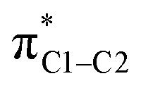 are intensified (Fig. 3) and large negative contributions are found for the σ
para term. This behavior is seen for both σC1–C and σC1–H NLMOs (Table 1). Accordingly, the NO2 group in para position causes a de-shielding of C1, while in meta there is little effect. As in the case of the NH2 substituent (but with an opposite trend), the density changes from the occupied π orbitals cause reverse effects in the low-energy π* orbitals, which reinforce the paramagnetic perturbations of the σ framework.
The increased C1 shielding effect of the NO2 substituent in ortho position requires further explanation. According to the overall VDD σ charge (and, indirectly, the π charge), an increase of the paramagnetic de-shielding would be expected. However, the calculated shielding displays the opposite behavior. Table 2 collects individual shielding contributions of the σC1–C,H NLMOs. It is seen that σC1–C2 is responsible for the positive shielding effect of the NO2 substituent in ortho position, relative to benzene. In contrast, σC1–C6 and σC1–H display similar de-shielding trends as found for the para position. In fact, the weight of C1 in these orbitals (ESI, Tables S5–S7†) shows that the overall σ density accumulation in ortho position is caused by σC1–C6 and σC1–H, whereas σC1–C2 is associated with a depletion of electron density. The calculated trends in Table 2 are therefore fully compatible with the C1 weight argument (Fig. 3) used to rationalize the o,m,p-NH2 and p-NO2 effects.
Table 2. σC1–C2 and σC1–C6 NLMO contributions to the σ11 shielding component, and σC1–H NLMO contributions to the σ22 component of the σ para term of the C1 shielding tensor for benzene and NO2–benzene (ppm). ortho (o-), meta (m-), and para (p-) is the C1 position relative to R.
| NLMO | R |
|||
| H | o-NO2 | m-NO2 | p-NO2 | |
| σC1–C2 | –131.60 | –116.49 | –129.70 | –136.54 |
| σC1–C6 | –131.60 | –133.87 | –131.77 | –136.54 |
| σC1–H | –140.42 | –144.75 | –142.82 | –152.35 |
The peculiar influence of σC1–C2 is explained as follows: C1 is the NMR nucleus, and for ortho substitution C2 is the carbon bound to the nitro group. Fig. 4 shows that the inductive σ effect of NO2 is particularly large at C2 (0.1 electron density depletion), due to the strong electron-withdrawing inductive effect of the NO2 group. This goes along with a considerable polarization of σC1–C2, shifting the weight from C1 to C2, as shown in Table S5 in the ESI.† While there is an overall increase of the σ electron density on C1, the σC1–C2 polarizes in the opposite way. The reduced σ para de-shielding caused by the σC1–C2 bond out-weighs the contributions from all other orbitals. Accordingly, the NO2 group causes an increased shielding in ortho position.
Conclusions
The σ bonding orbitals spanning the C1 carbon of interest (σC1–C2, σC1–C6, and σC1–H) are identified as responsible for the NMR shielding/de-shielding effects caused by π electron donating and withdrawing substituents depending on their position relative to C1. The π orbitals do not explain these effects, as conventionally suggested in chemistry textbooks, for two reasons: (i) the nuclear magnetic shielding is not related to the electron density in a simple way because it is a response property. Charge accumulation/depletion arguments must be made on a per-orbital basis and potentially take into account the corresponding effects on low lying unoccupied orbitals. (ii) Electron deformation density patterns induced in the π system by electron donating or withdrawing groups cause a mirror pattern in the σ system that is crucial to understand the related NMR shielding effects.
Because of the magnetic coupling of occupied σ with unoccupied π orbitals in the paramagnetic shielding mechanism, there are additional implicit dependencies of the C1 shielding on the deformation density patterns induced by the R-substituents. For example, the substituent effects on the occupied π orbitals affect the low-energy unoccupied π* orbitals, which couple magnetically with the occupied σ orbitals. The π* trends reinforce those in the occupied σ orbitals. For NO2, the increased shielding in ortho position is caused by a polarization of the C1–C2 σ bond toward the substituent, despite the electron deformation density indicating an overall σ accumulation at C1.
In summary, the classical organic chemistry concepts about the reactivity and regioselectivity of the benzene ring in electrophilic aromatic substitutions are not in a simple way related to the carbon NMR chemical shifts. However, the analysis shows that in a more indirect way there is an obvious relationship. A study of both the σ and π orbital sets is needed in order to relate the carbon chemical shift trends to the π electron density accumulation and depletion patterns in the substituted benzene rings. Since the ortho–meta–para patterns in the π electron density cause mirroring changes in the σ framework, the chemical effects of the R groups that manifest in electrophilic substitutions are ultimately responsible for the observed 13C NMR shifts. These effects persist in multi-substituted benzenes, e.g. with additional halogen groups, as we will report in a follow-up study.
Acknowledgments
We acknowledge FAPESP for financial support (2011/17357-3, 2013/03477-2, and 2015/08541-6), scholarships to R. V. V. (2012/12414-1 and 2015/20106-3) and a fellowship to L. C. D. (2014/21930-9). We are grateful for fellowships from CNPq to C. F. T. and L. C. D. (202068/2015-3). J. A. acknowledges the National Science Foundation (CHE-1560881) for financial support. The authors thank the Center for Computational Research (CCR) at the University at Buffalo for providing computational resources. Thanks are extended to Dr Célia Fonseca Guerra for providing information about the VDD analysis.
Footnotes
References
- Jacobsen N. E., NMR Spectroscopy Explained: Simplified Theory, Applications and Examples for Organic Chemistry and Structural Biology, John Wiley & Sons, Hoboken, USA, 2007. [Google Scholar]
- Simpson J. H., Organic Structure Determination Using 2-D NMR Spectroscopy, Elsevier, Oxford, UK, 2008. [Google Scholar]
- Clayden J., Greevs N., Warren S. and Wothers P., Organic Chemistry, Oxford University Press, USA, 1st edn, 2000. [Google Scholar]
- Carey F. A. and Sundberg R. J., Advanced Organic Chemistry, Part A: Structure and Mechanisms, Springer, New York, USA, 5th edn, 2007. [Google Scholar]
- Krygowski T. M., Oziminski W. P. J. Mol. Model. 2014;20:2352. doi: 10.1007/s00894-014-2352-z. [DOI] [PubMed] [Google Scholar]
- Palusiak M., Domagała M., Dominikowska J., Bickelhaupt F. M. Phys. Chem. Chem. Phys. 2014;16:4752–4763. doi: 10.1039/c3cp54089h. [DOI] [PubMed] [Google Scholar]
- Campanelli A. R., Domenicano A., Ramondo F., Hargittai I. J. Phys. Chem. A. 2004;108:4940–4948. [Google Scholar]
- Stasyuk O. A., Szatylowicz H., Krygowski T. M., Fonseca Guerra C. Phys. Chem. Chem. Phys. 2016;18:11624–11633. doi: 10.1039/c5cp07483e. [DOI] [PubMed] [Google Scholar]
- Szatylowicz H., Stasyuk O. A., Fonseca Guerra C., Krygowski T. M. Crystals. 2016;6:29. doi: 10.1039/c5cp07483e. [DOI] [PubMed] [Google Scholar]
- Zhang H., Jiang X., Wu W., Mo Y. Phys. Chem. Chem. Phys. 2016;18:11821–11828. doi: 10.1039/c6cp00471g. [DOI] [PubMed] [Google Scholar]
- Rasala D., Gawinecki R. Magn. Reson. Chem. 1992;30:740–745. [Google Scholar]
- Rasala D., Gawinecki R. Magn. Reson. Chem. 1993;31:38–44. [Google Scholar]
- Zakrzewska A., Gawinecki R., Kolehmainen E., Ośmiałowski B. Int. J. Mol. Sci. 2005;6:52–62. [Google Scholar]
- Dumont E., Chaquin P. Chem. Phys. Lett. 2007;435:354–357. [Google Scholar]
- Verma R. P., Hansch C. Chem. Rev. 2011;111:2865–2899. doi: 10.1021/cr100125d. [DOI] [PubMed] [Google Scholar]
- Chen G., Wu X., Cao C., Liu F., Zeng R., Liu W. Magn. Reson. Chem. 2015;53:172–177. doi: 10.1002/mrc.4148. [DOI] [PubMed] [Google Scholar]
- Arunima S., Kurur N. D. Magn. Reson. Chem. 2005;43:132–138. doi: 10.1002/mrc.1520. [DOI] [PubMed] [Google Scholar]
- Nummert V., Piirsalu M., Mäemets V., Vahur S., Koppel I. A. J. Phys. Org. Chem. 2009;22:1155–1165. [Google Scholar]
- Sen Gupta S. K., Shrivastava R. Magn. Reson. Chem. 2011;49:700–704. doi: 10.1002/mrc.2802. [DOI] [PubMed] [Google Scholar]
- Baranac-Stojanović M. RSC Adv. 2014;4:308–321. [Google Scholar]
- Baranac-Stojanović M., Koch A., Kleinpeter E. Chem.–Eur. J. 2012;18:370–376. doi: 10.1002/chem.201101882. [DOI] [PubMed] [Google Scholar]
- Baerends E. J., Ziegler T., Autschbach J., Bashford D., Bérces A., Bickelhaupt F. M., Bo C., Boerrigter P. M., Cavallo L., Chong D. P., Deng L., Dickson R. M., Ellis D. E., van Faassen M., Fan L., Fischer T. H., Fonseca Guerra C., Ghysels A., Giammona A., van Gisbergen S. J. A., Götz A. W., Groeneveld J. A., Gritsenko O. V., Grüning M., Gusarov S., Harris F. E., van den Hoek P., Jacob C. R., Jacobsen H., Jensen L., Kaminski J. W., van Kessel G., Kootstra F., Kovalenko A., Krykunov M. V., van Lenthe E., McCormack D. A., Michalak A., Mitoraj M., Neugebauer J., Nicu V. P., Noodleman L., Osinga V. P., Patchkovskii S., Philipsen P. H. T., Post D., Pye C. C., Ravenek W., Rodríguez J. I., Ros P., Schipper P. R. T., Schreckenbach G., Seldenthuis J. S., Seth M., Snijders J. G., Solà M., Swart M., Swerhone D., Velde G. te, Vernooijs P., Versluis L., Visscher L., Visser O., Wang F., Wesolowski T. A., van Wezenbeek E. M., Wiesenekker G., Wolff S. K., Woo T. K. and Yakovlev A. L., Amsterdam Density Functional, SCM, Theoretical Chemistry, Vrije Universiteit, Amsterdam, The Netherlands, http://www.scm.com, accessed 03/17.
- Velde G. te, Bickelhaupt F. M., Baerends E. J., van Gisbergen S. J. A., Fonseca Guerra C., Snijders J. G., Ziegler T. J. Comput. Chem. 2001;22:931–967. [Google Scholar]
- Fonseca Guerra C., Snijders J. G., Te Velde G., Baerends E. J. Theor. Chem. Acc. 1998;99:391. [Google Scholar]
- Adamo C., Barone V. J. Chem. Phys. 1999;110:6158–6170. [Google Scholar]
- Franchini M., Philipsen P. H. T., Visscher L. J. Comput. Chem. 2013;34:1819–1827. doi: 10.1002/jcc.23323. [DOI] [PubMed] [Google Scholar]
- Klamt A., Schüürmann G. J. Chem. Soc., Perkin Trans. 2. 1993:799–805. [Google Scholar]
- Bohmann J. A., Weinhold F., Farrar T. C. J. Chem. Phys. 1997;107:1173–1184. [Google Scholar]
- Autschbach J. J. Chem. Phys. 2008;128:164112. doi: 10.1063/1.2905235. [DOI] [PubMed] [Google Scholar]
- Autschbach J., Zheng S. Magn. Reson. Chem. 2008;46:S48–S55. [Google Scholar]
- Glendening E. D., Badenhoop J. K., Reed A. E., Carpenter J. Ė., Bohmann J. A., Morales C. M. and Weinhold F., NBO 6.0, theoretical chemistry institute, University of Wisconsin, Madison, 2013. http://nbo.chem.wisc.edu, accessed 03/17.
- Fonseca Guerra C., Handgraaf J.-W., Baerends E. J., Bickelhaupt F. M. J. Comput. Chem. 2004;25:189–210. doi: 10.1002/jcc.10351. [DOI] [PubMed] [Google Scholar]
- Guillaumes L., Simon S., Fonseca Guerra C. ChemistryOpen. 2015;4:318–327. doi: 10.1002/open.201402132. [DOI] [PMC free article] [PubMed] [Google Scholar]
- Grutzner J. B., Chemical shift theory. Orbital symmetry and charge effects on chemical shifts, in Recent advances in organic NMR spectroscopy, Norell Press, Landisville, NJ, 1987, pp. 17–42. [Google Scholar]
- Berger S., Fleischer U., Geletneky C., Lohrenz J. C. W. Chem. Ber. 1995;128:1183–1186. [Google Scholar]
Associated Data
This section collects any data citations, data availability statements, or supplementary materials included in this article.


